EP4195373A1 - Battery package, and battery module - Google Patents
Battery package, and battery module Download PDFInfo
- Publication number
- EP4195373A1 EP4195373A1 EP21852499.9A EP21852499A EP4195373A1 EP 4195373 A1 EP4195373 A1 EP 4195373A1 EP 21852499 A EP21852499 A EP 21852499A EP 4195373 A1 EP4195373 A1 EP 4195373A1
- Authority
- EP
- European Patent Office
- Prior art keywords
- battery
- electrode
- conductive sheet
- recessed portion
- lid
- Prior art date
- Legal status (The legal status is an assumption and is not a legal conclusion. Google has not performed a legal analysis and makes no representation as to the accuracy of the status listed.)
- Pending
Links
Images
















Classifications
-
- H—ELECTRICITY
- H01—ELECTRIC ELEMENTS
- H01M—PROCESSES OR MEANS, e.g. BATTERIES, FOR THE DIRECT CONVERSION OF CHEMICAL ENERGY INTO ELECTRICAL ENERGY
- H01M50/00—Constructional details or processes of manufacture of the non-active parts of electrochemical cells other than fuel cells, e.g. hybrid cells
- H01M50/10—Primary casings; Jackets or wrappings
- H01M50/102—Primary casings; Jackets or wrappings characterised by their shape or physical structure
- H01M50/103—Primary casings; Jackets or wrappings characterised by their shape or physical structure prismatic or rectangular
-
- H—ELECTRICITY
- H01—ELECTRIC ELEMENTS
- H01M—PROCESSES OR MEANS, e.g. BATTERIES, FOR THE DIRECT CONVERSION OF CHEMICAL ENERGY INTO ELECTRICAL ENERGY
- H01M10/00—Secondary cells; Manufacture thereof
- H01M10/04—Construction or manufacture in general
- H01M10/0436—Small-sized flat cells or batteries for portable equipment
-
- H—ELECTRICITY
- H01—ELECTRIC ELEMENTS
- H01M—PROCESSES OR MEANS, e.g. BATTERIES, FOR THE DIRECT CONVERSION OF CHEMICAL ENERGY INTO ELECTRICAL ENERGY
- H01M10/00—Secondary cells; Manufacture thereof
- H01M10/05—Accumulators with non-aqueous electrolyte
- H01M10/056—Accumulators with non-aqueous electrolyte characterised by the materials used as electrolytes, e.g. mixed inorganic/organic electrolytes
- H01M10/0561—Accumulators with non-aqueous electrolyte characterised by the materials used as electrolytes, e.g. mixed inorganic/organic electrolytes the electrolyte being constituted of inorganic materials only
- H01M10/0562—Solid materials
-
- H—ELECTRICITY
- H01—ELECTRIC ELEMENTS
- H01M—PROCESSES OR MEANS, e.g. BATTERIES, FOR THE DIRECT CONVERSION OF CHEMICAL ENERGY INTO ELECTRICAL ENERGY
- H01M10/00—Secondary cells; Manufacture thereof
- H01M10/05—Accumulators with non-aqueous electrolyte
- H01M10/058—Construction or manufacture
- H01M10/0585—Construction or manufacture of accumulators having only flat construction elements, i.e. flat positive electrodes, flat negative electrodes and flat separators
-
- H—ELECTRICITY
- H01—ELECTRIC ELEMENTS
- H01M—PROCESSES OR MEANS, e.g. BATTERIES, FOR THE DIRECT CONVERSION OF CHEMICAL ENERGY INTO ELECTRICAL ENERGY
- H01M10/00—Secondary cells; Manufacture thereof
- H01M10/42—Methods or arrangements for servicing or maintenance of secondary cells or secondary half-cells
- H01M10/425—Structural combination with electronic components, e.g. electronic circuits integrated to the outside of the casing
-
- H—ELECTRICITY
- H01—ELECTRIC ELEMENTS
- H01M—PROCESSES OR MEANS, e.g. BATTERIES, FOR THE DIRECT CONVERSION OF CHEMICAL ENERGY INTO ELECTRICAL ENERGY
- H01M50/00—Constructional details or processes of manufacture of the non-active parts of electrochemical cells other than fuel cells, e.g. hybrid cells
- H01M50/10—Primary casings; Jackets or wrappings
- H01M50/102—Primary casings; Jackets or wrappings characterised by their shape or physical structure
- H01M50/109—Primary casings; Jackets or wrappings characterised by their shape or physical structure of button or coin shape
-
- H—ELECTRICITY
- H01—ELECTRIC ELEMENTS
- H01M—PROCESSES OR MEANS, e.g. BATTERIES, FOR THE DIRECT CONVERSION OF CHEMICAL ENERGY INTO ELECTRICAL ENERGY
- H01M50/00—Constructional details or processes of manufacture of the non-active parts of electrochemical cells other than fuel cells, e.g. hybrid cells
- H01M50/10—Primary casings; Jackets or wrappings
- H01M50/102—Primary casings; Jackets or wrappings characterised by their shape or physical structure
- H01M50/11—Primary casings; Jackets or wrappings characterised by their shape or physical structure having a chip structure, e.g. micro-sized batteries integrated on chips
-
- H—ELECTRICITY
- H01—ELECTRIC ELEMENTS
- H01M—PROCESSES OR MEANS, e.g. BATTERIES, FOR THE DIRECT CONVERSION OF CHEMICAL ENERGY INTO ELECTRICAL ENERGY
- H01M50/00—Constructional details or processes of manufacture of the non-active parts of electrochemical cells other than fuel cells, e.g. hybrid cells
- H01M50/10—Primary casings; Jackets or wrappings
- H01M50/147—Lids or covers
- H01M50/148—Lids or covers characterised by their shape
- H01M50/153—Lids or covers characterised by their shape for button or coin cells
-
- H—ELECTRICITY
- H01—ELECTRIC ELEMENTS
- H01M—PROCESSES OR MEANS, e.g. BATTERIES, FOR THE DIRECT CONVERSION OF CHEMICAL ENERGY INTO ELECTRICAL ENERGY
- H01M50/00—Constructional details or processes of manufacture of the non-active parts of electrochemical cells other than fuel cells, e.g. hybrid cells
- H01M50/10—Primary casings; Jackets or wrappings
- H01M50/147—Lids or covers
- H01M50/155—Lids or covers characterised by the material
- H01M50/157—Inorganic material
- H01M50/159—Metals
-
- H—ELECTRICITY
- H01—ELECTRIC ELEMENTS
- H01M—PROCESSES OR MEANS, e.g. BATTERIES, FOR THE DIRECT CONVERSION OF CHEMICAL ENERGY INTO ELECTRICAL ENERGY
- H01M50/00—Constructional details or processes of manufacture of the non-active parts of electrochemical cells other than fuel cells, e.g. hybrid cells
- H01M50/10—Primary casings; Jackets or wrappings
- H01M50/147—Lids or covers
- H01M50/166—Lids or covers characterised by the methods of assembling casings with lids
- H01M50/169—Lids or covers characterised by the methods of assembling casings with lids by welding, brazing or soldering
-
- H—ELECTRICITY
- H01—ELECTRIC ELEMENTS
- H01M—PROCESSES OR MEANS, e.g. BATTERIES, FOR THE DIRECT CONVERSION OF CHEMICAL ENERGY INTO ELECTRICAL ENERGY
- H01M50/00—Constructional details or processes of manufacture of the non-active parts of electrochemical cells other than fuel cells, e.g. hybrid cells
- H01M50/10—Primary casings; Jackets or wrappings
- H01M50/183—Sealing members
- H01M50/186—Sealing members characterised by the disposition of the sealing members
-
- H—ELECTRICITY
- H01—ELECTRIC ELEMENTS
- H01M—PROCESSES OR MEANS, e.g. BATTERIES, FOR THE DIRECT CONVERSION OF CHEMICAL ENERGY INTO ELECTRICAL ENERGY
- H01M50/00—Constructional details or processes of manufacture of the non-active parts of electrochemical cells other than fuel cells, e.g. hybrid cells
- H01M50/20—Mountings; Secondary casings or frames; Racks, modules or packs; Suspension devices; Shock absorbers; Transport or carrying devices; Holders
- H01M50/202—Casings or frames around the primary casing of a single cell or a single battery
-
- H—ELECTRICITY
- H01—ELECTRIC ELEMENTS
- H01M—PROCESSES OR MEANS, e.g. BATTERIES, FOR THE DIRECT CONVERSION OF CHEMICAL ENERGY INTO ELECTRICAL ENERGY
- H01M50/00—Constructional details or processes of manufacture of the non-active parts of electrochemical cells other than fuel cells, e.g. hybrid cells
- H01M50/20—Mountings; Secondary casings or frames; Racks, modules or packs; Suspension devices; Shock absorbers; Transport or carrying devices; Holders
- H01M50/271—Lids or covers for the racks or secondary casings
- H01M50/273—Lids or covers for the racks or secondary casings characterised by the material
- H01M50/282—Lids or covers for the racks or secondary casings characterised by the material having a layered structure
-
- H—ELECTRICITY
- H01—ELECTRIC ELEMENTS
- H01M—PROCESSES OR MEANS, e.g. BATTERIES, FOR THE DIRECT CONVERSION OF CHEMICAL ENERGY INTO ELECTRICAL ENERGY
- H01M50/00—Constructional details or processes of manufacture of the non-active parts of electrochemical cells other than fuel cells, e.g. hybrid cells
- H01M50/20—Mountings; Secondary casings or frames; Racks, modules or packs; Suspension devices; Shock absorbers; Transport or carrying devices; Holders
- H01M50/298—Mountings; Secondary casings or frames; Racks, modules or packs; Suspension devices; Shock absorbers; Transport or carrying devices; Holders characterised by the wiring of battery packs
-
- H—ELECTRICITY
- H01—ELECTRIC ELEMENTS
- H01M—PROCESSES OR MEANS, e.g. BATTERIES, FOR THE DIRECT CONVERSION OF CHEMICAL ENERGY INTO ELECTRICAL ENERGY
- H01M50/00—Constructional details or processes of manufacture of the non-active parts of electrochemical cells other than fuel cells, e.g. hybrid cells
- H01M50/30—Arrangements for facilitating escape of gases
-
- H—ELECTRICITY
- H01—ELECTRIC ELEMENTS
- H01M—PROCESSES OR MEANS, e.g. BATTERIES, FOR THE DIRECT CONVERSION OF CHEMICAL ENERGY INTO ELECTRICAL ENERGY
- H01M50/00—Constructional details or processes of manufacture of the non-active parts of electrochemical cells other than fuel cells, e.g. hybrid cells
- H01M50/50—Current conducting connections for cells or batteries
-
- H—ELECTRICITY
- H01—ELECTRIC ELEMENTS
- H01M—PROCESSES OR MEANS, e.g. BATTERIES, FOR THE DIRECT CONVERSION OF CHEMICAL ENERGY INTO ELECTRICAL ENERGY
- H01M50/00—Constructional details or processes of manufacture of the non-active parts of electrochemical cells other than fuel cells, e.g. hybrid cells
- H01M50/50—Current conducting connections for cells or batteries
- H01M50/531—Electrode connections inside a battery casing
-
- H—ELECTRICITY
- H01—ELECTRIC ELEMENTS
- H01M—PROCESSES OR MEANS, e.g. BATTERIES, FOR THE DIRECT CONVERSION OF CHEMICAL ENERGY INTO ELECTRICAL ENERGY
- H01M50/00—Constructional details or processes of manufacture of the non-active parts of electrochemical cells other than fuel cells, e.g. hybrid cells
- H01M50/50—Current conducting connections for cells or batteries
- H01M50/543—Terminals
- H01M50/547—Terminals characterised by the disposition of the terminals on the cells
-
- H—ELECTRICITY
- H01—ELECTRIC ELEMENTS
- H01M—PROCESSES OR MEANS, e.g. BATTERIES, FOR THE DIRECT CONVERSION OF CHEMICAL ENERGY INTO ELECTRICAL ENERGY
- H01M50/00—Constructional details or processes of manufacture of the non-active parts of electrochemical cells other than fuel cells, e.g. hybrid cells
- H01M50/50—Current conducting connections for cells or batteries
- H01M50/572—Means for preventing undesired use or discharge
- H01M50/584—Means for preventing undesired use or discharge for preventing incorrect connections inside or outside the batteries
- H01M50/59—Means for preventing undesired use or discharge for preventing incorrect connections inside or outside the batteries characterised by the protection means
- H01M50/593—Spacers; Insulating plates
-
- H—ELECTRICITY
- H01—ELECTRIC ELEMENTS
- H01M—PROCESSES OR MEANS, e.g. BATTERIES, FOR THE DIRECT CONVERSION OF CHEMICAL ENERGY INTO ELECTRICAL ENERGY
- H01M2220/00—Batteries for particular applications
- H01M2220/30—Batteries in portable systems, e.g. mobile phone, laptop
-
- H—ELECTRICITY
- H01—ELECTRIC ELEMENTS
- H01M—PROCESSES OR MEANS, e.g. BATTERIES, FOR THE DIRECT CONVERSION OF CHEMICAL ENERGY INTO ELECTRICAL ENERGY
- H01M2300/00—Electrolytes
- H01M2300/0017—Non-aqueous electrolytes
- H01M2300/0065—Solid electrolytes
-
- Y—GENERAL TAGGING OF NEW TECHNOLOGICAL DEVELOPMENTS; GENERAL TAGGING OF CROSS-SECTIONAL TECHNOLOGIES SPANNING OVER SEVERAL SECTIONS OF THE IPC; TECHNICAL SUBJECTS COVERED BY FORMER USPC CROSS-REFERENCE ART COLLECTIONS [XRACs] AND DIGESTS
- Y02—TECHNOLOGIES OR APPLICATIONS FOR MITIGATION OR ADAPTATION AGAINST CLIMATE CHANGE
- Y02E—REDUCTION OF GREENHOUSE GAS [GHG] EMISSIONS, RELATED TO ENERGY GENERATION, TRANSMISSION OR DISTRIBUTION
- Y02E60/00—Enabling technologies; Technologies with a potential or indirect contribution to GHG emissions mitigation
- Y02E60/10—Energy storage using batteries
Definitions
- the present disclosure relates to a battery package and a battery module.
- Patent Document 1 describes a solid-state battery in which a battery laminate body is accommodated in a sealed case that can be mounted on a substrate. Electrodes of the sealed case and the battery laminate body are connected by wire bonding.
- Patent Document 2 describes a chip-type electric double-layer capacitor in which an electric double-layer capacitor is mounted in an accommodation space of an outer case. An upper electrode of the electric double-layer capacitor and an external terminal of the outer case are electrically connected by a conductive sheet. The conductive sheet is connected to the upper electrode of the electric double-layer capacitor. The conductive sheet is bent to pass the side of the electric double-layer capacitor and is connected to a terminal exposed to the accommodation space.
- Patent Document 3 describes a solid-state battery in which a battery material is accommodated in an accommodation member including an insulating base material and a lid member.
- the insulating base material has an accommodation recessed portion for accommodating the battery material, and a negative electrode layer of a battery element body is connected to a negative electrode terminal by way of the lid member.
- a battery package comprises an insulating substrate having a first surface, a second surface on a side opposite to the first surface, and a recessed portion which opens in the first surface and in which a battery is accommodated; a frame portion surrounding the recessed portion on the first surface; a wiring conductor comprising a first electrode located on a bottom surface of the recessed portion, a second electrode located on the first surface between the frame portion and the recessed portion, a first external electrode located on the second surface and electrically connected to the first electrode, and a second external electrode located on the second surface and electrically connected to the second electrode; a conductive sheet electrically connected to the second electrode and extending over an opening of the recessed portion above the first surface; and a lid closing the frame portion.
- a battery module comprises the battery package having the configuration described above; and a battery accommodated in the recessed portion of the battery package and comprising a lower surface electrode electrically connected to the first electrode and an upper surface electrode electrically connected to the conductive sheet.
- a lid side or a first surface side of an insulating substrate in the battery package may be referred to as an upper side
- an insulating substrate side or a second surface side of the insulating substrate in the battery package may be referred to as a lower side
- the vertical direction may be referred to as a height direction (thickness direction) in the description.
- FIG. 1 is a perspective view illustrating an outer appearance of an example of a battery module.
- FIG. 2 is an exploded perspective view of the battery module of FIG. 1 .
- a long dashed line with dot end portions indicates that there is an electrical connection.
- FIG. 3 is a plan view illustrating an example of the battery module of FIG. 1 in a state in which a lid is removed.
- FIG. 4 is a plan view illustrating an example of the battery module of FIG. 1 in a state in which the lid and a conductive sheet are removed.
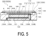
- FIG. 5 is a cross-sectional view taken along line V-V in FIG. 3 .
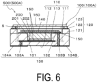
- FIG. 6 is a cross-sectional view taken along line VI-VI in FIG. 3 .
- FIG. 7 is a plan view illustrating an example of the battery module of FIG. 1 in a state in which the lid, the conductive sheet, a battery, and the like are removed.
- FIG. 8 is a bottom view illustrating an example of the battery module of FIG. 1 .
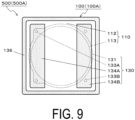
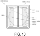
- FIGs. 9 and 10 are bottom views of the battery module of FIG. 1 illustrating a state in which a seal pattern is formed on the second surface of the insulating substrate.
- FIG. 11 is a partially enlarged cross-sectional view of a battery module using a thin-film type all-solid-state battery as a battery.
- FIG. 12 is a partially enlarged cross-sectional view of a battery module using a plurality of thin-film type all-solid-state batteries as batteries.
- a part of the first electrode or the like is shaded with dots so as to be easily distinguished from the others.
- a battery package 100(100A) includes an insulating substrate 110, and the insulating substrate 110 has a first surface 111, a second surface 112 on the side opposite to the first surface 111, and a recessed portion 113 opening in the first surface 111.
- the battery package 100(100A) includes a frame portion (frame body) 120 surrounding the recessed portion 113 on the first surface 111, and a wiring conductor 130.
- the wiring conductor 130 includes a first electrode 131 located on the bottom surface of the recessed portion 113, a second electrode 132 located on the first surface 111 between the frame portion 120 and the recessed portion 113, a first external electrode 134A located on the second surface 112, and a second external electrode 134B located on the second surface 112.
- the battery package 100(100A) includes a conductive sheet 140 electrically connected to the second electrode 132, and the conductive sheet 140 extends over the opening of the recessed portion 113 above the first surface 111.
- the battery package 100(100A) includes a lid 160 that closes the frame portion 120.
- the recessed portion 113 of the insulating substrate 110 is for accommodating a battery 200.
- the size of the recessed portion 113 in plan view is larger than the size of the battery 200 in plan view, and the depth of the recessed portion 113 may be about the same as the thickness of the battery 200.
- the first electrode 131 is provided on the bottom surface of the recessed portion 113 of the insulating substrate 110.
- the first electrode 131 may extend from the bottom surface of the recessed portion 113 to the inside of the insulating substrate 110.
- the first electrode 131 may cover the entire bottom surface of the recessed portion 113.
- the extended portion of the first electrode 131 and the first external electrode 134A are electrically connected by a first connection wiring 133A.
- the first electrode 131 can be electrically connected to a lower surface electrode 201 of the battery 200 accommodated in the recessed portion 113.
- the lower surface electrode 201 of the battery 200 is a negative electrode or a positive electrode.
- the first connection wiring 133A is located at a thick portion of the insulating substrate 110 and thus excels in strength.
- the first electrode 131 need not extend to the inside of the insulating substrate 110, and the first connection wiring may penetrate from the bottom surface of the recessed portion 113 to the second surface 112 to be connected to the first external electrode 134A. In this case, the path from the battery 200 to the first external electrode 134A is short and resistance is further reduced, and hence power can be efficiently extracted from the battery 200 accommodated in the recessed portion 113.
- the first external electrode 134A and the second external electrode 134B may extend from the second surface 112 of the insulating substrate 110 to side surfaces (also including a corner between the side surfaces).
- the second electrode 132 is provided outside the recessed portion 113 in the first surface 111 of the insulating substrate 110.
- the second electrode 132 and the second external electrode 134B are electrically connected to each other by a second connection wiring 133B. Since both the first external electrode 134A and the second external electrode 134B are located on the second surface 112 of the insulating substrate 110, the battery package 100(100A), in other words, a battery module 500(500A) can be surface-mounted on a mounting substrate.
- the frame portion 120 surrounding the recessed portion 113 is provided on the first surface 111 of the insulating substrate 110.
- the frame portion 120 is provided at an outer edge portion of the first surface 111, and the second electrode 132 is located on the inner side of the frame portion 120. That is, the second electrode 132 is located between the frame portion 120 and the recessed portion 113 in the first surface 111.
- the frame portion 120 includes an insulating frame body 121, a frame-shaped metal film 122 on the insulating frame body 121, and a metal frame body 123 joined onto the frame-shaped metal film 122 with a brazing material.
- the insulating frame body 121 is located on the first surface 111 of the insulating substrate 110 and is integrated with the insulating substrate 110.
- the insulating substrate 110 can also be regarded as having the recessed portion 113 with a small opening at the bottom surface of a recessed portion with a large opening. In other words, the insulating substrate 110 can be regarded as having two stages of recessed portions.
- the frame-shaped metal film 122 may be formed by metallization on the upper surface of the insulating frame body 121 made of, for example, ceramic.
- the metal frame body 123 may be joined, for example, to the frame-shaped metal film 122 with a brazing material.
- a nickel film may be formed on the surfaces of the metal frame body 123 and the frame-shaped metal film 122 by a plating method to improve j oinability with the brazing material.
- a material having a small difference in thermal expansion from ceramic may be used, and for example, an iron-nickel (Fe-Ni) alloy or an iron-nickel-cobalt (Fe-Ni-Co) alloy may be used.
- the conductive sheet 140 is provided extending over the opening of the recessed portion 113 above the first surface 111.
- the conductive sheet 140 is electrically connected to the second electrode 132. Since the conductive sheet 140 extends over the recessed portion 113, it can be electrically connected to an upper surface electrode 202 of the battery 200 accommodated in the recessed portion 113.
- the upper surface electrode 202 of the battery 200 is a positive electrode or a negative electrode.
- the frame portion 120 includes the insulating frame body 121 located on the first surface 111, and the metal frame body 123 is located over the upper surface of the insulating frame body 121.
- the conductive sheet 140 is located on the inner side of the insulating frame body 121 on the first surface 111.
- the surface (first surface 111) on which the conductive sheet 140 is located and the surface (the upper surface of the insulating frame body 121) on which the metal frame body 123 is located are located at different positions in the height direction.
- the battery package 100(100A) and the battery module 500(500A) each having a smaller size can be obtained.
- two second electrodes 132 are provided on the first surface 111.
- the conductive sheet 140 is connected to the two second electrodes 132. That is, the conductive sheet 140 is connected to the wiring conductor 130 at two locations.
- the conductive sheet 140 may be connected to the second electrode 132 at at least one location.
- the conductive sheet 140 may have a size large enough to substantially cover the opening portion of the recessed portion 113. In other words, the conductive sheet 140 may have a size large enough to cover the upper surface electrode 202 of the battery 200 accommodated in the recessed portion 113.
- the conductive sheet 140 may be connected to the second electrode 132 while covering 50% or more of the opening area of the recessed portion 113.
- the conductive sheet 40 can be electrically connected to at least 50% or more of the area of the upper surface electrode 202 of the battery 200.
- the connection resistance between the conductive sheet 40 and the upper surface electrode 202 of the battery 200 is reduced and the electricity extraction efficiency is increased, by electrically connecting the conductive sheet 40 and 50% or more of the area of the upper surface electrode 202 of the battery 200.
- the battery 200 can be protected from radiant heat from the lid 160 when the lid 160 is joined or when the battery module 500(500A) is mounted.
- the opening of the frame portion 120 on the opposite side to (upper side of) the insulating substrate 110 is closed by the lid 160.
- the lid 160 is joined to the metal frame body 123 of the frame portion 120.
- a space S surrounded by the lid 160, the frame portion 120, and the insulating substrate 110 is hermetically sealed.
- the ratio of the space S to the battery module 500 may be set to, for example, 5% to 30%.
- the gap amount between the lid 160 and the conductive sheet 140 may be set to, for example, 0.1 mm to 0.8 mm.
- the space S or the gap amount described above is set in such a manner, and for example, the battery 200 is expanded or a gas is generated therein with an increase in the temperature of the battery 200, an increase in the internal stress or the internal pressure of the battery 200 is alleviated and the durability of the battery 200 is improved. Even when stress is applied to the lid 160 from the outside, the stress applied to the battery 200 is reduced by the space S between the lid 160 and the battery 200.
- the space S may be sealed in an atmosphere such as a nitrogen atmosphere, an argon gas atmosphere, a vacuum, or the like, for example, at a dew point of lower than or equal to - 20°C. In this case, even when the environmental temperature and the humidity increase, the chemical reaction between moisture or oxygen and battery materials is suppressed, improving the heat resistance and the life of the battery 200.
- an atmosphere such as a nitrogen atmosphere, an argon gas atmosphere, a vacuum, or the like, for example, at a dew point of lower than or equal to - 20°C.
- the battery module 500 is configured by accommodating the battery 200 in the recessed portion 113 of the battery package 100, electrically connecting the lower surface electrode 201 of the battery 200 to the first electrode 131, and electrically connecting the upper surface electrode 202 of the battery 200 to the conductive sheet 140.
- the battery module 500 includes the battery package 100 and the battery 200 accommodated in the recessed portion 113 of the battery package 100 and electrically connected to the first electrode 131 and the conductive sheet 140.
- the battery 200 includes the electrodes (the upper surface electrode 202 and the lower surface electrode 201) on the upper surface and the lower surface.
- the battery 200 including electrodes on the upper and lower sides is surface-mounted on the mounting substrate by accommodating the battery 200 in the battery package 100 of the present disclosure.
- the internal configuration and materials of the battery 200 are not particularly limited as long as the battery 200 includes electrodes on the upper surface and the lower surface.
- the battery 200 may be an all-solid-state battery having a structure in which a solid electrolyte is sandwiched between a positive electrode and a negative electrode.
- the battery 200 may include current collectors on the outer side of the positive electrode and the negative electrode.
- a seal pattern 136 surrounding the periphery of the first external electrode 134A and the second external electrode 134B may be located on the second surface 112 of the insulating substrate 110.
- the seal pattern 136 is made of a conductive material such as a solderable metal.
- the seal pattern 136 may surround each of the periphery of the first external electrode 134A and the periphery of the second external electrode 134B.
- the seal pattern 136 is made of a solderable conductive material
- the first external electrode 134A and the second external electrode 134B located on the inner side of the seal pattern 136 can be sealed by joining the seal pattern 136 and the pattern of the mounting substrate with solder. Then, since the sealing by solder joint can be performed simultaneously with the joining of the first external electrode 134A and the second external electrode 134B with the electrodes of the mounting substrate by solder, efficiency is high and productivity is high, and another sealing material such as a resin or the like is unnecessary. An electric leakage, a short circuit between adjacently mounted electronic components, or the like due to moisture or the like at the time of cleaning after mounting the battery module 500(500A) can be prevented by sealing the first external electrode 134A and the second external electrode 134B.
- the peripheral edge portion of the battery module 500(500A) can be sealed with a sealing material such as a resin material when the battery module 500(500A) is surface-mounted on the mounting substrate.
- the conductive sheet 140 is connected to the second electrode 132 on the first surface 111 and extends over the opening of the recessed portion 113 for accommodating the battery 200.
- the second electrode 132 is connected to the second connection wiring 133B in the insulating substrate 110 and connected to the second external electrode 134B on the second surface 112 of the insulating substrate 110. Therefore, an insulator of the insulating substrate 110 is located between the recessed portion 113 for accommodating the battery 200 and the wiring conductor 130 (second connection wiring 133B) located on the side of the recessed portion 113.
- the battery package 100(100A) is obtained in which the possibility of a short circuit between the upper surface electrode 202 and the lower surface electrode 201 of the battery 200 accommodated in the recessed portion 113 is reduced.
- the conductive sheet 140 connecting the upper surface electrode 202 of the battery 200 and the wiring conductor 130 (second electrode 132) can be widened to cover the battery 200 accommodated in the recessed portion 113. Therefore, the connecting material connecting the battery 200 accommodated in the recessed portion 113 and the wiring conductor 130 (second electrode 132) has a lower electric resistance than a thin wire.
- the battery package 100 of the present disclosure excels in extraction efficiency of power from the battery 200 accommodated in the recessed portion 113.
- the lower surface electrode 201 of the battery 200 and the first external electrode 134A are electrically connected mainly by the first electrode 131 located on the bottom surface of the recessed portion 113 and the first connection wiring 133A.
- the first electrode 131 is located on the bottom surface of the recessed portion 113 close to the second surface 112 of the insulating substrate 110 where the first external electrode 134A is located. Therefore, the wiring length (current path) of the first connection conductor 133A located between the bottom surface of the recessed portion 113 and the second surface 112 is short.
- This current path does not include a portion where electric resistance increases, such as a connecting portion like a wire. Therefore, the electric resistance between the lower surface electrode 201 of the battery 200 and the first external electrode 134A is relatively low, and the extraction efficiency of power from the battery 200 is excellent.
- the lid 160 closes the opening of the frame portion 120 located on the outer side of the second electrode 132 connected to the conductive sheet 140. Since the opening of the frame portion 120 is located above the conductive sheet 140, the battery 200 can be hermetically sealed without a short circuit between the lid 160 and the conductive sheet 140.
- the battery 200 can be hermetically sealed without causing a short circuit between the upper surface electrode 202 and the lower surface electrode 201 of the battery 200, and without being discharged to the outside through the lid 160. Therefore, in the case of the battery package 100(100A) of the present disclosure, power from the battery 200 can be efficiently extracted to the outside through the first external electrode 134A and the second external electrode 134B.
- the battery module 500(500A) of the present disclosure since the battery 200 is accommodated in the battery package 100(100A) described above, the battery module 500(500A) can be surface-mounted on the mounting substrate, and the power of the battery 200 accommodated in the battery module 500(500A) can be efficiently extracted.
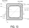
- FIG. 13 is a plan view illustrating another example of a battery module in a state in which a lid is removed.
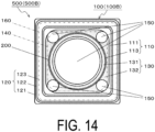
- FIG. 14 is a plan view illustrating another example of the battery module in a state in which the lid and a conductive sheet are removed.
- FIG. 15 is a cross-sectional view taken along line XV-XV in FIG. 13 .
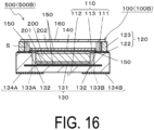
- FIG. 16 is a cross-sectional view along line XVI-XVI in FIG. 13 .
- FIG. 17 is a plan view illustrating another example of a battery module in a state in which a lid is removed.
- FIG. 18 is a plan view illustrating another example of the battery module in a state in which the lid and a conductive sheet are removed.
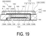
- FIG. 19 is a cross-sectional view taken along line XIX-XIX in FIG. 17 .
- FIG. 20 is a cross-sectional view taken along line XX-XX in FIG. 17 .
- the battery packages 100(100B, 100C) of the battery modules 500(500B, 500C) of the examples illustrated in FIGs. 13 to 20 do not include the insulating frame body 121 unlike the battery package 100 (100A) of the battery module 500(500A) of the example illustrated in FIGs. 1 to 12 .
- the frame portion 120 includes the frame-shaped metal film 122 provided on the first surface 111 of the insulating substrate 110, and the metal frame body 123 joined on the frame-shaped metal film 122. Accordingly, thinning of the battery packages 100 (100B, 100C) and the battery modules 500(500B, 500C) is promoted.
- the configurations of the frame-shaped metal film 122 and the metal frame body 123 may be the same as and/or similar to those of the battery package 100(100B, 100C) of the battery module 500(500A) in the example illustrated in FIGs. 1 to 12 .
- the battery package 100(100A) of the example illustrated in FIGs. 1 to 12 includes two second electrodes 132, and the conductive sheet 140 and the wiring conductor 130 (second electrodes 132) are connected at two locations.
- the battery packages 100(100B, 100C) of the examples illustrated in FIGs. 13 to 20 includes one second electrode 132 having a frame shape along the opening of the recessed portion 113.
- the conductive sheet 140 and the wiring conductor 130 (second electrode 132) are connected at four locations. In other words, four corner portions of the conductive sheet 140 and the wiring conductor 130 (second electrode 132) are connected.
- the conductive sheet 140 and the second electrode 132 are connected at a plurality of locations. Therefore, the connection area between the conductive sheet 140 and the second electrode 132 increases, the connection between the conductive sheet 140 and the second electrode 132 has a lower resistance, and the power of the battery 200 can be more efficiently extracted.
- a corner portion of the conductive sheet 140 can be avoided from entering between the battery 200 and the recessed portion 113, and a short circuit can be avoided.
- the second electrode 132 has a frame shape surrounding the recessed portion 113.
- the connection area between the conductive sheet 140 and the second electrode 132 further increases. Therefore, the connection between the conductive sheet 140 and the second electrode 132 has a much lower resistance, and the power of the battery 200 can be more efficiently extracted.
- a corner portion of the conductive sheet 140 can be avoided from entering between the battery 200 and the recessed portion 113, and a short circuit can be avoided.
- connection between the conductive sheet 140 and the second electrode 132 is not only an electrical connection but also a mechanical connection. That is, the conductive sheet 140 is fixed to the second electrode 132 at a plurality of locations. A plurality of electrical connecting locations are also a plurality of mechanical fixing locations (a plurality of mechanical connecting locations). Therefore, the strength of the mechanical connection between the conductive sheet 140 and the second electrode 132 and reliability of the connection therebetween improve.
- the conductive sheet 140 is fixed to the first surface 111 of the insulating substrate 110 by way of a conductive joining material 150 and the second electrode 132.
- the conductive sheet 140 is fixed to the insulating substrate 110 at two locations sandwiching the recessed portion 113 in plan view.
- the conductive sheet 140 is fixed to the insulating substrate 110 at four locations surrounding the recessed portion 113 in plan view.
- the shape connecting the four connecting locations is a quadrangular shape, and the conductive sheet 140 is fixed to the insulating substrate 110 at four locations sandwiching the recessed portion 113 in plan view.
- the 17 to 20 has a frame shape surrounding the recessed portion 113, and the conductive sheet 140 is fixed to the insulating substrate 110 over the entire periphery surrounding the recessed portion 113. It can also be said that the conductive sheet 140 is fixed at a position enclosing the recessed portion 113 from all directions in plan view.
- the conductive sheet 140 is fixed to the first surface 111 at the position sandwiching the recessed portion 113 in plan view, and thus the connecting location of the conductive sheet 140 and the portion that is a part of the conductive sheet 140 and is located over the recessed portion 113 sandwiched between the connecting locations do not move in the vertical direction. Therefore, the battery 200 is sandwiched and fixed by the first electrode 131 and the conductive sheet 140.
- the electrical connection between the electrodes of the battery 200 and the first electrode 131 and the conductive sheet 140 can be suppressed from being lost due to the positional displacement of the battery 200 with respect to the insulating substrate 110. Therefore, an increase in resistance at the connecting portion between the electrodes of the battery 200 and the first electrode 131 and the conductive sheet 140 can be suppressed.
- the battery 200 can be held by the conductive sheet 140.
- the battery package 100(100B) of the example illustrated in FIGs. 13 to 16 when the conductive sheet 140 and the wiring conductor 130 are connected at two locations, and the two connecting locations pass through the central portion of the recessed portion 113, the effect of holding the battery 200 by the conductive sheet 140 is further enhanced.
- the conductive sheet 140 is electrically connected to the insulating substrate 110 at all four fixing locations in order to reduce the resistance of the connection between the conductive sheet 140 and the second electrode 132.
- the conductive sheet 140 need not be electrically connected to the insulating substrate 110 at all the plurality of fixing locations.
- two of four corner portions of the conductive sheet 140 having a quadrangular shape are connected to the second electrodes 132.
- the remaining two corner portions of the conductive sheet 140 may be joined to the first surface 111 of the insulating substrate 110, in which case the conductive sheet 140 is fixed to the first surface 111 at positions sandwiching the recessed portion 113 in the diagonal direction of the conductive sheet 140, as in the battery package 100(100B) of the example illustrated in FIGs. 13 to 16 .
- the conductive sheet 140 is fixed to a portion of the first surface 111 where the second electrode 132 is not provided, without being electrically connected to the portion.
- a portion of the conductive sheet 140 that is not electrically connected may be joined to the first surface 111 with a non-conductive joining material.
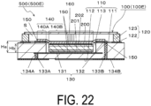
- FIGs. 21 and 22 are cross-sectional views illustrating another example of a battery module.
- a battery module 500(500D) of the example illustrated in FIG. 21 has a configuration similar to that of the battery module 500(500A) of the example illustrated in FIGs. 1 to 12 , and is an example in which the metal frame body 123 of the frame portion 120 is omitted, and the number of connecting locations between the conductive sheet 140 and the second electrode 132 is increased.
- the upper surface of the battery 200 protrudes upward from the opening portion of the recessed portion 113.
- a central portion of the conductive sheet 140 connected to the upper surface electrode 202 of the battery 200 is curved upward to have a protruding shape.
- a battery module 500(500E) of the example illustrated in FIG. 22 has a configuration similar to that of the battery module 500(400B) of the example illustrated in FIGs. 13 to 16 , and is an example in which the configuration of the frame portion 120 in the battery module 500(500D) of the example illustrated in FIG. 21 is changed.
- a battery package 100E of the example illustrated in FIG. 22 has a configuration similar to those of the battery packages 100(100B, 100C) of the examples illustrated in FIGs. 13 to 20 .
- the upper surface of the battery 200 is located below the opening portion of the recessed portion 113.
- a central portion of conductive sheet 140 connected to the upper surface electrode 202 of the battery 200 is curved downward to have a protruding shape.
- the conductive sheet 140 connected to the upper surface electrode 202 of the battery 200 has a thin sheet shape. Therefore, as shown in FIGs. 21 and 22 , even when the thickness of the battery 200 to be accommodated does not match the depth of the recessed portion 113, the conductive sheet 140 changes its form following the position of the upper surface of the battery 200, and the conductive sheet 140 and the upper surface electrode 202 of the battery 200 are reliably connected. Therefore, the battery package 100 of the present disclosure can incorporate batteries 200 having different sizes, and the versatility of the battery package 100 is enhanced.
- the upper surface (upper surface electrode 202) of the battery 200 is located above the opening portion of the recessed portion 113. More strictly, the upper surface of the battery 200 is located above the second electrode 132.
- a central portion of the conductive sheet 140 is curved upward to have a protruding shape.
- the central portion of the conductive sheet 140 connected to the battery 200 is located at a position higher than the outer edge portion of the conductive sheet 140 connected to the second electrode 132.
- the first region 140B located on the battery 200 is located at a position higher than the second region 140A located on the first surface 111 of the insulating substrate 110.
- the reference position in height in this case is the surface (upper surface) of the first electrode 131 located on the bottom surface of the recessed portion 113.
- the reference position may be the second surface 112 of the insulating substrate 110 or the bottom surface of the recessed portion 113.
- height Hb of the first region 140B located on the battery 200 is higher than height Ha of the second region 140A located on the first surface 111 in the entire region of the conductive sheet 140.
- the battery 200 is sandwiched and fixed by the first electrode 131 and the conductive sheet 140.
- the conductive sheet 140 is curved downward at the outer edge of the first region 140B, and the second region 140A is fixed to the first surface 111 of the insulating substrate 110 by way of the second electrode 132 and the like.
- the conductive sheet 140 is fixed to the second electrode 132 so as to cover a portion of the battery 200 protruding upward to be higher than the second electrode 132.
- the possibility of positional displacement of the battery 200 in the planar direction along the bottom surface of the recessed portion 113 (direction orthogonal to the thickness direction of the battery package 100) is reduced by the conductive sheet 140.
- the conductive sheet 140 When the conductive sheet 140 is an elastic body, the conductive sheet 140 is brought into contact with the upper surface of the battery 200, and the conductive sheet 140 is slightly stretched and connected to the second electrode 132, so that the battery 200 can be pressed against the first electrode 131 by the elastic force of the conductive sheet 140.
- the battery 200 has a structure in which a positive electrode layer 240, an electrolyte layer 230, and a negative electrode layer 220 are layered, the adhesion between these layers can be increased by pressing the battery 200 with the conductive sheet 140. Therefore, separation or displacement between the members included in the battery 200 can be prevented.
- the pressure with which the battery 200 is pressed can reduce the electric resistance between the positive electrode layer 240 (negative electrode layer 220) and the electrolyte layer 230, and thus the electricity extraction efficiency can be enhanced.
- the conductive sheet 140 presses the upper surface electrode 202 of the battery 200, and the conductive joining material 150 is provided between the upper surface electrode 202 of the battery 200 and the conductive sheet 140. Furthermore, the conductive joining material 150 is also provided between the lower surface electrode 201 of the battery 200 and the first electrode 131.
- the conductive joining material 150 is provided between the upper surface electrode 202 of the battery 200 and the conductive sheet 140, and between the lower surface electrode 201 of the battery 200 and the first electrode 131.
- the upper surface electrode 202 of the battery 200 and the conductive sheet 140 are joined by the conductive joining material 150
- the lower surface electrode 201 of the battery 200 and the first electrode 131 are joined by the conductive joining material 150.
- the electrical connection between the upper surface electrode 202 of the battery 200 and the conductive sheet 140 and between the lower surface electrode 201 of the battery 200 and the first electrode 131 may be made by direct contact, but the electric resistance of the connecting portions is further reduced by interposing the conductive joining material 150 therebetween. Since the mechanical connection strength therebetween increases, the possibility of positional displacement of the battery 200 with respect to the insulating substrate 110 is reduced, and the electrical connection reliability of the battery module 500(500A, for example) is improved.
- the lid 160 closes the opening portion of the frame portion 120 and is joined to the upper surface of the frame portion 120.
- the lid 160 merely needs to be able to seal the opening of the frame portion 120 by closing it.
- the lid 160 is made of ceramic or metal
- a material having a small thermal expansion difference from the insulating substrate 110 made of ceramic for example, an iron-nickel (Fe-Ni) alloy or an iron-nickel-cobalt (Fe-Ni-Co) alloy may be used.
- Examples of joining the lid 160 to the frame portion 120 include joining using a joining material such as a resin adhesive, glass, a brazing material containing solder, or the like. In terms of airtightness, joining using glass or a brazing material as a joining material is preferable.
- a joining material such as a resin adhesive, glass, a brazing material containing solder, or the like.
- joining using glass or a brazing material as a joining material is preferable.
- the frame-shaped metal film 122 or the metal frame body 123 is located at the upper surface of the frame portion 120.
- the outer edge portion of the lower surface of the lid 160 made of ceramic is also provided with a film same as and/or similar to the frame-shaped metal film 122.
- the lid 160 When the lid 160 is made of metal, the lid 160 can be joined to the frame portion 120 by welding. In the battery package 100, the lid 160 is made of metal and is welded to the frame portion 120. The hermetic sealing property of the battery package 100 improves.
- the lid 160 may be joined to the metal frame body 123 of the frame portion 120 as in the examples illustrated in FIGs. 5 , 6 , 15 , 16 , 19 , 20 , and 22 , or may be joined to the frame-shaped metal film 122 of the frame portion 120 as in the example illustrated in FIG. 21 .
- seam welding is used.
- direct seam welding, laser welding, or electron beam welding is used.
- a joining material such as a brazing material
- the lid 160 is joined to the frame portion 120 through whole heating by reflow heating.
- seam welding direct seam welding, laser welding, or electron beam welding
- the welding is performed by local heating of only the joining portion, and thus the influence of heat on the battery 200 is reduced.
- seam welding is resistance welding via the metal frame body 123, and is advantageous in local heating of the joining portion.
- the frame portion 120 includes the frame-shaped metal film 122 on the insulating frame body 121.
- the frame portion 120 includes the frame-shaped metal film 122 and the metal frame body 123 on the insulating frame body 121.
- the joining portion of the lid 160 and the frame-shaped metal film 122 or the metal frame body 123 is separated from the joining portion of the battery 200 and the conductive sheet 140 and the connecting portion of the conductive sheet 140 and the second electrode 132. Accordingly, a thermal conduction path from the joining portion of the lid 160 to the battery 200 and the like is long, and such a thermal conduction path includes the insulating frame body 121 having a relatively low thermal conductivity.
- the influence on the battery 200 by the heat generated at the time of joining the lid 160 to the frame portion 120 is further reduced.
- FIG. 23 is a plan view illustrating another example of a battery module in a state in which a lid and a conductive sheet are removed.
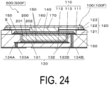
- FIG. 24 is a cross-sectional view taken along line XXIV-XXIV in FIG. 23 .
- a spacer 170 is interposed between the lid 160 and the conductive sheet 140, unlike in the battery modules 500(500A, for example) of the examples illustrated in FIGs. 1 to 22 .
- the spacer 170 may be located between the lid 160 and the conductive sheet 140, and may be in contact with the lid 160 and the conductive sheet 140.
- an elastic body such as rubber or spring may be used.
- the conductive sheet 140 is pressed against the upper surface electrode 202 of the battery 200 by the elastic force of the spacer 170 by making the thickness of the spacer 170 larger than the interval between the lid 160 and the conductive sheet 140.
- the spacer 170 is pressed against the conductive sheet 140 by the elasticity of the lid 160 having a thin plate shape and the conductive sheet 140 can be pressed against the upper surface electrode 202 of the battery 200, by making the thickness of the spacer 170 larger than the interval between the upper surface of the frame portion 120 (metal frame body 123) and the upper surface of the conductive sheet 140.
- butyl rubber or the like that can be thermally expanded after sealing with the lid 160 may be used as the spacer 170.
- the butyl rubber or the like is in contact with one of the lid 160 and the conductive sheet 140 at the time of sealing with the lid 160.
- the butyl rubber or the like is brought into contact with both the lid 160 and the conductive sheet 140 by being thermally expanded after the sealing with the lid 160. Therefore, heat at the time of joining the lid 160 is not transmitted to the battery 200 via the spacer 170, and the possibility of breakage of the battery 160 is reduced.
- the spacer 170 made of an insulating material may be used so as to prevent discharge from the lid 160 due to a short circuit between the lid 160 and the upper surface electrode of the battery 200. Even if the spacer 170 does not have an insulating property, when the electric resistance of the spacer 170 is sufficiently higher than the electric resistance of the conductive sheet 140, most of the current from the battery 200 flows to the conductive sheet 140, so that discharge from the lid 160 can be suppressed. In other words, when the electrical conductivity of the spacer 170 is sufficiently low as compared with the electrical conductivity of the conductive sheet 140, discharge from the lid 160 can be suppressed.
- an insulating film may be provided on the lower surface of the spacer 170.
- a protective sheet having an insulating property for protecting the battery 200 may be provided between the spacer 170 and the conductive sheet 160.
- FIGs. 25 and 26 are cross-sectional views illustrating other examples of a battery module.
- the lid 160 includes a convex portion 161 in contact with the conductive sheet 140.
- the convex portion 161 is formed so as to protrude downward by increasing the thickness of a central portion of the lid 160.
- the lid 160 including the convex portion 161 may be produced by joining the convex portion 161 to a flat plate, or may be produced by metal mold pressing or the like.
- the conductive sheet 140 is pressed against the upper surface electrode 202 of the battery 200 without using the spacer 170. That is, the convex portion 161 located on the lower surface of the lid 160 can press the conductive sheet 140 against the upper surface electrode 202 of the battery 200.
- the conductive sheet 140 is pressed against the upper surface electrode 202 of the battery 200 by the convex portion 161
- the electric resistance between the conductive sheet 140 and the battery 200 is reduced, and the power extraction efficiency of the battery 200 is increased.
- the convex portion 161 has a flat pressing surface, an area of a portion in the conductive sheet 140 that is uniformly pressed is increased, and the power extraction efficiency of the battery 200 is further enhanced. The possibility of positional displacement of the battery 200 with respect to the insulating substrate 110 is reduced.
- the lid 160 has a plate shape, and the thickness of the entire region of the lid 160 is substantially even.
- the lid 160 includes a protruding portion 162 in contact with the conductive sheet 140.
- the protruding portion 162 is formed such that a central portion of the lid 160 protrudes downward.
- the protruding portion 162 has a flat pressing surface 162f for pressing the conductive sheet 140 toward the battery 200 side.
- the area of the pressing surface 162f of the protruding portion 162 is preferably greater than or equal to 50% of the opening area of the recessed portion 113.
- the protruding portion 162 may press the conductive sheet 140 from above toward the battery 200 side by vertical inversion.
- the protruding portion 162 in a state before the inversion is indicated by an alternate long and two short dashed line. It is desirable to seal the space S in a state in which the pressure is reduced to lower than the atmospheric pressure so that the protruding portion 162 can be easily inverted vertically.
- the lid 160 including the protruding portion 162 may be produced by punching a metal plate.
- the lid 160 including the protruding portion 162 may be produced by punching a metal plate and performing press working.
- the protruding portion 162 may have a curved pressing surface instead of the flat pressing surface 162f.
- the lid 160 includes the protruding portion 162 as described above, the conductive sheet 140 is pressed against the upper surface electrode 202 of the battery 200 without using the spacer 170. That is, the protruding portion 162 located on the lower surface of the lid 160 can press the conductive sheet 140 against the upper surface electrode 202 of the battery 200.
- the conductive sheet 140 is pressed against the upper surface electrode 202 of the battery 200 by the protruding portion 162
- the electric resistance between the conductive sheet 140 and the battery 200 is reduced, and the power extraction efficiency of the battery 200 is increased.
- the protruding portion 162 presses the conductive sheet 140 by inversion after joining of the lid 160, the protruding portion 162 is not inverted at the time of joining of the lid 160 and is not in contact with the conductive sheet 140, and thus heat at the time of joining of the lid 160 is less likely to be conducted to the conductive sheet 140 and the battery 200.
- the lid 160 is joined by seam welding (resistance welding), for example, current applied at the time of joining the lid 160 is also not conducted to the battery 200 and the like. Therefore, the possibility of deterioration and breakage of the battery 200 is reduced.
- the protruding portion 162 When the battery 200 is expanded or a gas is generated therein with an increase in the temperature of the battery 200, the protruding portion 162 is inverted to have an outward protruding shape and the internal space S increases, so that an increase in the internal pressure can be alleviated.
- the conductive sheet 140 includes a conductor sheet 141 and an insulator sheet 142.
- the conductor sheet 141 electrically connects the battery 200 and the wiring conductor 130 (second electrode 132).
- the insulator sheet 142 ensures the insulating property between the conductor sheet 141 and the lid 160 made of metal.
- the conductive sheets 140 in the battery modules 500 may have a structure in which a copper foil and an insulating resin such as a polyimide resin are layered as in, for example, a flexible substrate.
- an insulating film may be provided on at least a portion (pressing surface) of a lower surface (surface on the conductive sheet 140 side) of the lid 160 that is to be brought into contact with the conductive sheet 140.
- the lid 160 When the electric resistance of the lid 160 is sufficiently higher than the electric resistance of the conductive sheet 140, most of the current from the battery 200 flows to the conductive sheet 140, so that discharge from the lid 160 can be suppressed. In other words, when the electrical conductivity of the lid 160 is sufficiently low as compared with the electrical conductivity of the conductive sheet 140, discharge from the lid 160 can be suppressed.
- the lid 160 when the lid 160 is made of an iron-nickel (Fe-Ni) alloy or an iron-nickel-cobalt (Fe-Ni-Co) alloy described above, a low resistance metal such as copper or aluminum may be used as a constituent material of the conductive sheet 140.
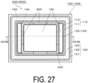
- FIG. 27 is a plan view illustrating another example of a battery module in a state in which a lid and a conductive sheet are removed.
- FIG. 28 is a cross-sectional view taken along line XXVIII-XXVIII in FIG. 27 .
- the shape of the recessed portion 113 of the insulating substrate 110 has a cylindrical shape with a circular shape in plan view and an even depth has been described, but the shape of the recessed portion 113 is not limited thereto, and can be a shape according to the shape of the battery 200.
- the shape of the recessed portion 113 of the battery package 100(100I) in plan view of the example illustrated in FIGs. 27 and 28 is a rectangular shape.
- the rectangular shape means not only an exact rectangle with right corners but also a rectangle with rounded corner portions.
- the shape of the recessed portion 113 in plan view may be a polygonal shape other than a quadrangular shape or an elliptical shape.
- the recessed portion 113 has an uneven depth and has a shape in which a central portion thereof has a deeper depth, and thus, the recessed portion 113 is a two-step recessed portion.
- the recessed portion 113 can be said to be a three-step recessed portion.
- the battery 200 of the battery module 500(500I) of the example illustrated in FIGs. 27 and 28 includes an upper surface electrode 202, a lower surface electrode 201, and a solid electrolyte 203 sandwiched between the upper surface electrode 202 and the lower surface electrode 201.
- the lower surface electrode 201 has a shape slightly smaller than the solid electrolyte 203 and the upper surface electrode 202, and the cross-sectional shape of the battery 200 of the example illustrated in FIGs. 27 and 28 is a downward protruding shape (T-shape).
- the cross-sectional shape of the recessed portion 113 is a shape according to the cross-sectional shape of the battery 200 of the example illustrated in FIGs. 27 and 28 .
- the size of the recessed portion 113 in plan view is larger than the size of the battery 200 in plan view, and there is a gap between the battery 200 and the inner wall of the recessed portion 113.
- the insulating member 300 is inserted into this gap.
- the insulating member 300 is located between the side surface of the battery 200 and the inner side surface of the recessed portion 113. The insulating member 300 further reduces the possibility of positional displacement of the battery 200 with respect to the insulating substrate 110.
- the battery 200 is more firmly fixed to the recessed portion 113. Since the insulating member 300 has an insulating property, the insulating property between the side surface of the battery 200 and the second electrode 132 is further enhanced. Since the gap between the side surface of the battery 200 and the inner side surface of the recessed portion 113 is filled with the insulating member 300, the possibility of a short circuit between the upper surface electrode 202 and the lower surface electrode 201 through the conductive sheet 140 is reduced.
- FIG. 29 is a cross-sectional view taken along line XXIX-XXIX in FIG. 30.
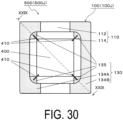
- FIG. 30 is a bottom view of another example of a battery module.
- the battery package 100 that accommodates only the battery 200 has been described, but an electronic component 400 and the like other than the battery 200 may be accommodated in the battery package 100(100J) of the example illustrated in FIGs. 29 and 30 .
- a space for accommodating the electronic component 400 may be provided, whereby the battery 200 and the electronic component 400 may be arranged overlapping each other in plane perspective so that the battery package 100(100J) and the battery module 500(500J) do not increase in size.
- the insulating substrate 110 of the battery package 100(100J) illustrated in the example of FIGs. 29 and 30 has a second recessed portion 114 for accommodating the electronic component 400, and the second recessed portion 114 opens in the second surface 112.
- a power supply IC for controlling the battery 200 may be mounted as the electronic component 400.
- the power supply IC is a semiconductor element for battery control.
- the power supply IC includes a DC/DC converter that supplies a constant power supply voltage, a reset IC that monitors the power supply, and a switch IC that turns on/off the power supply.
- the recessed portion 113 opening in the first surface 111 and the second recessed portion 114 opening in the second surface 112 are at positions overlapping each other in plane perspective.
- the battery 200 and the electronic component 400 (power supply IC) are mounted in an overlapping manner in plane perspective. Therefore, the operation of the battery 200 can be controlled, and the size of the battery module 500(500J) can be reduced.
- the electronic component 400 is fixed to the bottom surface of the second recessed portion 114 with a joining material that is not illustrated.
- An electrode (not illustrated) of the electronic component 400 and an internal electrode 135 provided on the bottom surface of the second recessed portion 114 are electrically connected by a bonding wire (conductive connecting material 410).
- the electrode of the electronic component 400 and the internal electrode 135 may be electrically and mechanically connected by flip-chip connection.
- the electronic component 400 such as a coil, a capacitor, or the like may be mounted in the second recessed portion 114.
- the opening of the second recessed portion 114 may be closed with a lid (not illustrated), or may be sealed by covering the electronic component 400 with a sealing resin.
- the dimension of the insulating substrate 110 is, for example, such that the length of one side of the quadrangle is 1 mm to 20 mm, and the thickness of the insulating substrate 110 is 0.5 mm to 5 mm.
- the dimension of the recessed portion 113 of the insulating substrate 110 can be set according to the size of the battery 200.
- the insulating substrate 110 is formed by layering a plurality of insulating layers.
- the insulating layers are made of an insulating material such as an aluminum oxide sintered body, a glass ceramic sintered body, a mullite sintered body, an aluminum nitride sintered body, or the like.
- the insulating substrate 110 is produced in the following manner. That is, first, ceramic green sheets to be insulating layers are produced. A plurality of quadrangular sheet-shaped ceramic green sheets are produced by forming raw material powder of aluminum oxide, silicon oxide, and the like into a sheet shape together with an appropriate organic binder and organic solvent. Next, a laminate body is produced by layering these ceramic green sheets. The recessed portion 113 is formed by providing a through hole in the ceramic green sheets using a metal mold or the like. Thereafter, the laminate body is fired at a temperature of 1300 to 1600°C to produce the insulating substrate 110.
- the insulating frame body 121 is formed simultaneously with the insulating substrate 110.
- a laminate body including a frame-shaped green sheet in which a through hole is provided with a metal mold or the like may be produced.
- the wiring conductor 130 (first electrode 131, second electrode 132, first connection wiring 133A, second connection wiring 133B, first external electrode 134A, second external electrode 134B) is provided on the surface of the insulating substrate 110 and inside thereof.
- the frame-shaped metal film 122 is provided on the first surface 111 of the insulating substrate 110 or the insulating frame body 121 of the frame portion 120.
- the first connection wiring 133A connecting the first electrode 131 and the first external electrode 134A and the second connection wiring 133B connecting the second electrode 132 and the second external electrode 134B are through-hole conductors penetrating the insulating substrate 110, for example.
- the first connection wiring 133A and the second connection wiring 133B are not limited thereto, and may include a conductor layer extending, inside the insulating substrate 110, in the surface direction of the first surface 111 and the second surface 112.
- the first connection wiring 133A or the second connection wiring 133B may be connected to the first external electrode 134A or the second external electrode 134B through the side surface from the inside of the insulating substrate 110.
- the side surface conductor forming a part of the first connection wiring 133A and the second connection wiring 133B may be a conductor filled in a recessed portion (groove portion) provided in the side surface of the insulating substrate 110.
- the first electrode 131 and the first external electrode 134A may overlap each other in plane perspective.
- the second electrode 132 and the second external electrode 134B may overlap each other in plane perspective.
- the first connection wiring 133A and the second connection wiring 133B serving as the through-hole conductors can be shortened to suppress power loss by the wirings.
- the first external electrode 134A and the second external electrode 134B may extend from the second surface 112 to the side surface of the insulating substrate 110.
- a plurality of first connection wirings 133A (through-hole conductors) and a plurality of second connection wirings 133B (through-hole conductors) may be provided.
- the number of the first connection wirings 133A (through-hole conductors) and the number of the second connection wirings 133B (through-hole conductors) are one or two, but may be more than two.
- the wiring conductor 130 and the frame-shaped metal film 122 mainly contain, for example, a metal such as tungsten, molybdenum, manganese, copper, silver, palladium, gold, platinum, nickel, or cobalt or a metal material of an alloy containing these metals as a conductor material.
- a metal material is provided on the surface of the insulating substrate 110, as a metal layer such as a metallized layer or a plated layer.
- the metal layer may be a single layer or a plurality of layers.
- the metal layer may be provided inside the insulating substrate 110 by metallization.
- the conductor layer extending in the surface direction of the first surface 111 and the second surface 112 and the frame-shaped metal film 122 can be formed as below when they are, for example, metallized layers of tungsten.
- the conductor layer and the frame-shaped metal film 122 can be formed by a method of printing a metal paste produced by mixing tungsten powder with an organic solvent and an organic binder at a predetermined position on the ceramic green sheets to be the insulating substrate 110 by a method such as a screen printing method and then performing firing.
- the conductor layer includes the first electrode 131, the second electrode 132, the first external electrode 134A, the second external electrode 134B, and the like of the wiring conductor 130.
- the seal pattern 136 can also be formed using a material and a manufacturing method same as and/or similar to those of the wiring conductor 130 and the like, and can be printed simultaneously with the first external electrode 134A and the second external electrode 134B. Therefore, it is easy to form the seal pattern 136.
- a plating layer of nickel, gold, or the like may be deposited on the exposed surface of the metallized layer exposed to the outside, such as the first electrode 131, the second electrode 132, the first external electrode 134A, the second external electrode 134B, the seal pattern 136, and the frame-shaped metal film 122 by a plating method such as an electrolytic plating method or an electroless plating method.
- the through-hole conductors of the first connection wiring 133A and the second connection wiring 133B can be formed by providing through holes at predetermined positions on the ceramic green sheets prior to the printing of the metal paste, and filling the through holes with the metal paste.
- a large number of wiring substrates including the insulating substrate 110, the wiring conductor 130, and the like may be formed from a plurality of substrate regions arrayed on a motherboard.
- a plurality of wiring substrates can be produced more efficiently by dividing the motherboard into substrate regions.
- a dividing groove may be provided along the boundary between the substrate regions on the motherboard.
- the conductive sheet 140 is made of a conductive material, has a sheet-like shape, and has a size large enough to cover 50% or more of the area of the upper surface electrode 202 of the battery 200 and allow connection therewith.
- a material containing a metal such as copper or aluminum, an alloy such as stainless steel, or the like may be used.
- the conductive sheet 140 may be made of only a conductive material, or may be made of a composite material of a conductive material and an insulating material.
- the conductive sheet 140 may have a structure in which a copper foil and an insulating resin such as a polyimide resin are layered as in the flexible substrate described above.
- the number of batteries 200 accommodated in the recessed portion 113 of the battery package 100 is not limited to one, and may be plural.
- a plurality of batteries 200 may be accommodated in one recessed portion 113 such that they are arranged in the surface direction (direction orthogonal to the thickness direction) of the bottom surface of the recessed portion 113, and the plurality of batteries 200 may be connected to one conductive sheet 140.
- a plurality of recessed portions 113 may be provided in the first surface 111 of the insulating substrate 110 in the surface direction, the battery 200 may be accommodated in each of the plurality of recessed portions 113, and the plurality of batteries 200 may be connected to one conductive sheet 140 overlapping the plurality of recessed portions 113.
- the plurality of first electrodes 131 located on the respective bottom surfaces of the plurality of recessed portions 113 may be connected to one first external electrode 134A.
- One large first electrode 131 connected to the first external electrode 134A may be exposed on the bottom surfaces of the plurality of recessed portions 113.
- the plurality of batteries 200 may be accommodated in an overlapping manner in one recessed portion 113 so as to be connected in series in the thickness direction (the depth direction of the recessed portion).
- the upper and lower batteries 200 are connected (joined) by contact connection or a conductive joining material.
- the volume energy density of the battery module 500(500A, for example) can be improved by mounting the plurality of batteries 200 in one battery package 100(100A, for example), as compared with the case where only one battery 200 is mounted. Furthermore, the material cost of the battery package 100(100A, for example) can be reduced, the entire battery mounting area can be downsized, and mounting efficiency can be enhanced by mounting the plurality of batteries 200 in one battery package 100(100A, for example) as compared with the case where the battery package 100(100A, for example) on which one battery 200 is mounted is arranged.
- the conductive sheet 140 of the examples illustrated in FIGs. 25 and 26 only the upper surface of the conductor sheet 141 on the lid 160 side is covered with the insulator sheet 142. A portion other than a portion connected to the battery 200 and the second electrode 132 on the lower surface of the conductor sheet 141 on the battery 200 side may also be covered with the insulator sheet 142.
- the composite material for example, a conductive resin obtained by dispersing a conductive material in a resin, or a conductive resin in which a conductive material is bonded with a resin may be used.
- the conductive sheet 140 is connected to the second electrode 132 by way of the conductive joining material 150, but when the conductive sheet 140 is made of a metal foil, the conductive sheet 140 may be joined to the second electrode 132 by resistance welding.
- solder or a conductive adhesive may be used.
- a conductive adhesive that allows joining at a low temperature may be used.
- silver nano paste may be used for electrical connection at a lower temperature.
- the spacer 170 is not limited to being made of the resin described above, and may be made of, for example, ceramic or metal.
- the spacer 170 is made of a conductive material such as metal, the surface of the spacer 170 may be covered with an insulating material.
- the battery module 500 may include a desiccant (not illustrated) that absorbs moisture.
- the desiccant may be located on the lower surface of lid 160, or may be located on the lower side of the lower surface electrode 201 of the battery 200.
- another small recessed portion may be further provided in the bottom surface of the recessed portion 113, and the desiccant may be disposed in the recessed portion.
- the desiccant may be located between the side surface of the battery 200 and the inner side surface of the recessed portion 113.
- the desiccant for example, silica gel or calcium chloride may be used.
- the battery 200 may be a coin cell in which battery materials such as an electrolyte material, a positive electrode, a negative electrode, and a separator are disposed in a metal container and sealed.
- a coin cell may also be referred to as a button cell.
- the battery 200 may be a primary battery or a secondary battery.
- the battery 200 includes in its category not only a chemical battery but also a power supply element such as an electric double-layer capacitor.
- the battery package 100(100A, for example) enables the coin cell to be surface-mounted on the mounting substrate.
- a battery material of the battery 200 is a sulfide-based battery material
- the use of an already-sealed coin cell as the batter 200 allows it to be easily sealed even not in a special working environment such as under a dry atmosphere to form the surface-mount type battery 200.
- the battery (coin cell) 200 can be surface-mounted on the mounting substrate even not in a special working environment such as under a dry atmosphere, and the productivity of a circuit board device can be enhanced.
- the battery (coin cell) 200 can be hermetically sealed at a higher level than a general coin cell by the battery package 100(100A, for example), and the life of the battery (coin cell) 200 is improved. Since the battery material of the battery 200 is doubly sealed with the metal container and the battery package 100(100A, for example), leakage of the sulfide material from the battery (coin cell) 200 can be significantly reduced.
- the battery module 500 may include a thin-film type all-solid-state battery as the battery 200.
- the thin-film type all-solid-state battery is the battery 200 in which the negative electrode layer 220, the electrolyte layer 230, and the positive electrode layer 240 are layered on a metal plate 210, and the metal plate 210 has a function of a current collector.
- the metal plate 210 is, for example, a plate made of copper, aluminum, stainless steel, or the like, and the metal plate 210 has a plate thickness of, for example, 0.1 mm to 0.5 mm.
- the gold negative electrode layer 220, the electrolyte layer 230, and the positive electrode layer 240 are formed by, for example, a vapor deposition method, a sputtering method, or the like.
- the thin-film type all-solid-state battery 200 may include a resin cover 250 that covers the end face of the negative electrode layer 220, the end face of the electrolyte layer 230, and the end face of the positive electrode layer 240, and the resin cover 250 is made of an insulating resin.
- the metal plate 210 corresponds to the lower surface electrode 201
- the positive electrode layer 240 corresponds to the upper surface electrode 202.
- the negative electrode layer 220, the electrolyte layer 230, and the positive electrode layer 240 are sequentially layered from the metal plate 210 below, but the negative electrode layer 220 and the positive electrode layer 240 may be reversely layered.
- the negative electrode layer 220 corresponds to the upper surface electrode 202.
- the position of the end face of the negative electrode layer 220, the position of the end face of the electrolyte layer 230, and the position of the end face of the positive electrode layer 240 may be displaced.
- the negative electrode layer 220, the electrolyte layer 230, and the positive electrode layer 240 may be made smaller or larger in the layering order.
- the electrolyte layer 230 may be larger than the positive electrode layer 240 and the negative electrode layer 220. In this case, a short circuit between the positive electrode layer 240 and the negative electrode layer 220 in the side surface direction can be prevented.
- Another metal plate 210 may be interposed between the positive electrode layer 240 and the conductive sheet 140 (conductive joining material 150).
- the conductive joining material 150 may be interposed between the another metal plate 210 and the positive electrode layer 240.
- the metal plate 210 on the positive electrode layer 240 (between the positive electrode layer 240 and the conductive sheet 140) corresponds to the upper surface electrode 202.
- the conductive joining material 150 may be interposed between the metal plate 210 corresponding to upper surface electrode 202 and the conductive sheet 140.
- One ends of the plurality of positive electrode layers 240 may be connected to each other, and the other ends of the plurality of negative electrode layers 220 may be connected to each other.
- the plurality of positive electrode layers 240 and the plurality of negative electrode layers 200 have a comb-like shape in longitudinal sectional view.
- the plurality of positive electrode layers 240 and the plurality of negative electrode layers 220 are disposed such that the two comb teeth mesh with each other, and the electrolyte layer 230 is disposed between the positive electrode layers 240 and the negative electrode layers 220.
- the battery module 500 may include a plurality of thin-film type all-solid-state batteries as the batteries 200.
- a plurality of thin-film type all-solid-state batteries 200 may be mounted in series in the recessed portion 113 of the battery package 100.
- the conductive joining material 150 may be interposed between the plurality of thin-film type all-solid-state batteries 200.
- the end portion of the electrolyte layer 230 may cover the end portion of the negative electrode layer 220.
- a plurality of thin-film type all-solid-state batteries 200 are efficiently manufactured by forming a thin film battery on a large metal plate and dividing the thin film battery into pieces with a predetermined size.
- the plurality of thin-film type all-solid-state batteries 200 may be connected by contact without any joining material interposed therebetween.
- the contact resistance between the plurality of thin-film type all-solid-state batteries 200 can be reduced.
- a thin-film all individual battery has high energy density, high safety, and an excellent recycle life, but it is difficult to form a thin-film all-solid-state battery in the recessed portion 113 of the battery package 100, and it is also difficult to handle an all-solid-state battery formed only of a thin film. Therefore, the productivity (production efficiency) of the battery module 500 including the thin-film all individual battery decreases.
- the thin-film type all-solid-state battery 200 in which the battery module 500 includes the metal plate 210 is used as the battery 200, mass production of the battery 200 becomes possible and productivity of the battery module 500 is improved.
- the battery 200 having a size that matches the recessed portion 113 of the insulating substrate 110 is cut out by dicing or the like and placed in the recessed portion 113 of the insulating substrate 110, so that the productivity of the battery module 500 is improved.
- the thin-film type all-solid-state battery 200 in which the battery module 500 includes the metal plate 210 is used as the battery 200
- the adhesion between the metal plate 210 and the negative electrode layer 220, the adhesion between the negative electrode layer 220 and the electrolyte layer 230, and the adhesion between the positive electrode layer 240 and the electrolyte layer 230 are increased. Therefore, the power extraction efficiency of the battery 200 is increased.
- examples of a constituent material of the insulating member 300 disposed between the outer side surface of the battery 200 and the inner side surface of the recessed portion 113 include a resin material such as an epoxy resin or a silicone resin.
- the constituent material of the insulating member 300 may be a composite material of ceramic particles and a resin material.
- the insulating member 300 may be formed by solidifying a liquid resin injected into the gap between the battery 200 and the inner side surface of the recessed portion 113.
- the insulating member 300 that is solid may be inserted and disposed in the gap between the battery 200 and the inner side surface of the recessed portion 113.
- insulating members 300 are arranged at intervals in the circumferential direction on each side portion of the gap having a quadrangular frame shape in plan view, but the arrangement is not limited to such an arrangement.
- the recessed portion 113 and the battery 200 have a circular shape in plan view, three insulating members 300 are disposed at intervals in the circumferential direction, so that positional displacement of the battery 200 with respect to the insulating substrate 110 is suppressed.
- the insulating member 300 may be disposed over the entire outer periphery of the battery 200.
Landscapes
- Chemical & Material Sciences (AREA)
- Chemical Kinetics & Catalysis (AREA)
- Electrochemistry (AREA)
- General Chemical & Material Sciences (AREA)
- Engineering & Computer Science (AREA)
- Inorganic Chemistry (AREA)
- Manufacturing & Machinery (AREA)
- Physics & Mathematics (AREA)
- Condensed Matter Physics & Semiconductors (AREA)
- General Physics & Mathematics (AREA)
- Microelectronics & Electronic Packaging (AREA)
- Battery Mounting, Suspending (AREA)
- Connection Of Batteries Or Terminals (AREA)
- Electric Double-Layer Capacitors Or The Like (AREA)
- Sealing Battery Cases Or Jackets (AREA)
Abstract
Description
- The present disclosure relates to a battery package and a battery module.
- Various forms of power supplies that can be surface-mounted on a mounting substrate together with electronic circuit components have been proposed as power supplies or auxiliary power supplies for small electronic devices.
- For example, Patent Document 1 describes a solid-state battery in which a battery laminate body is accommodated in a sealed case that can be mounted on a substrate. Electrodes of the sealed case and the battery laminate body are connected by wire bonding.
- Patent Document 2 describes a chip-type electric double-layer capacitor in which an electric double-layer capacitor is mounted in an accommodation space of an outer case. An upper electrode of the electric double-layer capacitor and an external terminal of the outer case are electrically connected by a conductive sheet. The conductive sheet is connected to the upper electrode of the electric double-layer capacitor. The conductive sheet is bent to pass the side of the electric double-layer capacitor and is connected to a terminal exposed to the accommodation space.
- Patent Document 3 describes a solid-state battery in which a battery material is accommodated in an accommodation member including an insulating base material and a lid member. The insulating base material has an accommodation recessed portion for accommodating the battery material, and a negative electrode layer of a battery element body is connected to a negative electrode terminal by way of the lid member.
-
- Patent Document 1:
JP 2010-118159 A - Patent Document 2:
JP 2011-14864 A - Patent Document 3:
WO 2012/141231 - In one aspect of the present disclosure, a battery package comprises an insulating substrate having a first surface, a second surface on a side opposite to the first surface, and a recessed portion which opens in the first surface and in which a battery is accommodated; a frame portion surrounding the recessed portion on the first surface; a wiring conductor comprising a first electrode located on a bottom surface of the recessed portion, a second electrode located on the first surface between the frame portion and the recessed portion, a first external electrode located on the second surface and electrically connected to the first electrode, and a second external electrode located on the second surface and electrically connected to the second electrode; a conductive sheet electrically connected to the second electrode and extending over an opening of the recessed portion above the first surface; and a lid closing the frame portion.
- In one aspect of the present disclosure, a battery module comprises the battery package having the configuration described above; and a battery accommodated in the recessed portion of the battery package and comprising a lower surface electrode electrically connected to the first electrode and an upper surface electrode electrically connected to the conductive sheet.
-
-
FIG. 1 is a perspective view illustrating an outer appearance of an example of a battery module. -
FIG. 2 is an exploded perspective view of the battery module ofFIG. 1 . -
FIG. 3 is a plan view illustrating an example of the battery module ofFIG. 1 in a state in which a lid is removed. -
FIG. 4 is a plan view illustrating an example of the battery module ofFIG. 1 in a state in which the lid and a conductive sheet are removed. -
FIG. 5 is a cross-sectional view taken along line V-V inFIG. 3 . -
FIG. 6 is a cross-sectional view taken along line VI-VI inFIG. 3 . -
FIG. 7 is a plan view illustrating an example of the battery module ofFIG. 1 in a state in which the lid, the conductive sheet, a battery, and the like are removed. -
FIG. 8 is a bottom view illustrating an example of the battery module ofFIG. 1 . -
FIG. 9 is a bottom view of the battery module ofFIG. 1 illustrating a state in which a seal pattern is formed on a second surface of an insulating substrate. -
FIG. 10 is a bottom view of the battery module ofFIG. 1 illustrating a state in which the seal pattern is formed on the second surface of the insulating substrate. -
FIG. 11 is a partially enlarged cross-sectional view of a battery module using a thin-film type all-solid-state battery as a battery. -
FIG. 12 is a partially enlarged cross-sectional view of a battery module using a plurality of thin-film type all-solid-state batteries as batteries. -
FIG. 13 is a plan view illustrating another example of a battery module in a state in which a lid is removed. -
FIG. 14 is a plan view illustrating another example of the battery module in a state in which the lid and a conductive sheet are removed. -
FIG. 15 is a cross-sectional view taken along line XV-XV inFIG. 13 . -
FIG. 16 is a cross-sectional view taken along line XVI-XVI inFIG. 13 . -
FIG. 17 is a plan view illustrating another example of a battery module in a state in which a lid is removed. -
FIG. 18 is a plan view illustrating another example of the battery module in a state in which the lid and a conductive sheet are removed. -
FIG. 19 is a cross-sectional view taken along line XIX-XIX inFIG. 17 . -
FIG. 20 is a cross-sectional view taken along line XX-XX inFIG. 17 . -
FIG. 21 is a cross-sectional view illustrating another example of a battery module. -
FIG. 22 is a cross-sectional view illustrating another example of a battery module. -
FIG. 23 is a plan view illustrating another example of the battery module in a state in which a lid and a conductive sheet are removed. -
FIG. 24 is a cross-sectional view taken along line XXIV-XXIV inFIG. 23 . -
FIG. 25 is a cross-sectional view illustrating another example of a battery module. -
FIG. 26 is a cross-sectional view illustrating another example of a battery module. -
FIG. 27 is a plan view illustrating another example of a battery module in a state in which a lid and a conductive sheet are removed. -
FIG. 28 is a cross-sectional view taken along line XXVIII-XXVIII inFIG. 27 . -
FIG. 29 is a cross-sectional view taken along line XXIX-XXIX inFIG. 30 . -
FIG. 30 is a bottom view of another example of a battery module. - A battery package and a battery module according to an embodiment of the present disclosure will be described with reference to the accompanying drawings. In the following description, a lid side or a first surface side of an insulating substrate in the battery package may be referred to as an upper side, and an insulating substrate side or a second surface side of the insulating substrate in the battery package may be referred to as a lower side. The vertical direction may be referred to as a height direction (thickness direction) in the description. This distinction between up (upper) and down (lower) is merely for the sake of convenience, and does not limit up (upper) and down (lower) when the battery module or the like is actually used.
-
FIG. 1 is a perspective view illustrating an outer appearance of an example of a battery module.FIG. 2 is an exploded perspective view of the battery module ofFIG. 1 . InFIG. 2 , a long dashed line with dot end portions indicates that there is an electrical connection.FIG. 3 is a plan view illustrating an example of the battery module ofFIG. 1 in a state in which a lid is removed.FIG. 4 is a plan view illustrating an example of the battery module ofFIG. 1 in a state in which the lid and a conductive sheet are removed.FIG. 5 is a cross-sectional view taken along line V-V inFIG. 3 .FIG. 6 is a cross-sectional view taken along line VI-VI inFIG. 3 .FIG. 7 is a plan view illustrating an example of the battery module ofFIG. 1 in a state in which the lid, the conductive sheet, a battery, and the like are removed.FIG. 8 is a bottom view illustrating an example of the battery module ofFIG. 1 .FIGs. 9 and10 are bottom views of the battery module ofFIG. 1 illustrating a state in which a seal pattern is formed on the second surface of the insulating substrate.FIG. 11 is a partially enlarged cross-sectional view of a battery module using a thin-film type all-solid-state battery as a battery.FIG. 12 is a partially enlarged cross-sectional view of a battery module using a plurality of thin-film type all-solid-state batteries as batteries. In the perspective views, each of the plan views, and the bottom views, a part of the first electrode or the like is shaded with dots so as to be easily distinguished from the others. - As shown in
FIGs. 1 to 6 , a battery package 100(100A) includes an insulatingsubstrate 110, and the insulatingsubstrate 110 has afirst surface 111, asecond surface 112 on the side opposite to thefirst surface 111, and a recessedportion 113 opening in thefirst surface 111. The battery package 100(100A) includes a frame portion (frame body) 120 surrounding the recessedportion 113 on thefirst surface 111, and awiring conductor 130. Thewiring conductor 130 includes afirst electrode 131 located on the bottom surface of the recessedportion 113, asecond electrode 132 located on thefirst surface 111 between theframe portion 120 and the recessedportion 113, a firstexternal electrode 134A located on thesecond surface 112, and a secondexternal electrode 134B located on thesecond surface 112. The battery package 100(100A) includes aconductive sheet 140 electrically connected to thesecond electrode 132, and theconductive sheet 140 extends over the opening of the recessedportion 113 above thefirst surface 111. The battery package 100(100A) includes alid 160 that closes theframe portion 120. - As shown in
FIGs. 2 ,5 and6 , the recessedportion 113 of the insulatingsubstrate 110 is for accommodating abattery 200. The size of the recessedportion 113 in plan view is larger than the size of thebattery 200 in plan view, and the depth of the recessedportion 113 may be about the same as the thickness of thebattery 200. - As shown in
FIGs. 5 to 8 , thefirst electrode 131 is provided on the bottom surface of the recessedportion 113 of the insulatingsubstrate 110. Thefirst electrode 131 may extend from the bottom surface of the recessedportion 113 to the inside of the insulatingsubstrate 110. Thefirst electrode 131 may cover the entire bottom surface of the recessedportion 113. The extended portion of thefirst electrode 131 and the firstexternal electrode 134A are electrically connected by afirst connection wiring 133A. Thefirst electrode 131 can be electrically connected to alower surface electrode 201 of thebattery 200 accommodated in the recessedportion 113. Thelower surface electrode 201 of thebattery 200 is a negative electrode or a positive electrode. - When the
first electrode 131 extends to the inside of the insulatingsubstrate 110, thefirst connection wiring 133A is located at a thick portion of the insulatingsubstrate 110 and thus excels in strength. Thefirst electrode 131 need not extend to the inside of the insulatingsubstrate 110, and the first connection wiring may penetrate from the bottom surface of the recessedportion 113 to thesecond surface 112 to be connected to the firstexternal electrode 134A. In this case, the path from thebattery 200 to the firstexternal electrode 134A is short and resistance is further reduced, and hence power can be efficiently extracted from thebattery 200 accommodated in the recessedportion 113. - The first
external electrode 134A and the secondexternal electrode 134B may extend from thesecond surface 112 of the insulatingsubstrate 110 to side surfaces (also including a corner between the side surfaces). - The
second electrode 132 is provided outside the recessedportion 113 in thefirst surface 111 of the insulatingsubstrate 110. Thesecond electrode 132 and the secondexternal electrode 134B are electrically connected to each other by asecond connection wiring 133B. Since both the firstexternal electrode 134A and the secondexternal electrode 134B are located on thesecond surface 112 of the insulatingsubstrate 110, the battery package 100(100A), in other words, a battery module 500(500A) can be surface-mounted on a mounting substrate. - As illustrated in
FIGs. 5 to 7 , theframe portion 120 surrounding the recessedportion 113 is provided on thefirst surface 111 of the insulatingsubstrate 110. Theframe portion 120 is provided at an outer edge portion of thefirst surface 111, and thesecond electrode 132 is located on the inner side of theframe portion 120. That is, thesecond electrode 132 is located between theframe portion 120 and the recessedportion 113 in thefirst surface 111. - In the battery package 100(100A) of the example illustrated in
FIGs. 1 to 12 , theframe portion 120 includes an insulatingframe body 121, a frame-shapedmetal film 122 on the insulatingframe body 121, and ametal frame body 123 joined onto the frame-shapedmetal film 122 with a brazing material. The insulatingframe body 121 is located on thefirst surface 111 of the insulatingsubstrate 110 and is integrated with the insulatingsubstrate 110. The insulatingsubstrate 110 can also be regarded as having the recessedportion 113 with a small opening at the bottom surface of a recessed portion with a large opening. In other words, the insulatingsubstrate 110 can be regarded as having two stages of recessed portions. - The frame-shaped
metal film 122 may be formed by metallization on the upper surface of the insulatingframe body 121 made of, for example, ceramic. Themetal frame body 123 may be joined, for example, to the frame-shapedmetal film 122 with a brazing material. A nickel film may be formed on the surfaces of themetal frame body 123 and the frame-shapedmetal film 122 by a plating method to improve j oinability with the brazing material. As themetal frame body 123, a material having a small difference in thermal expansion from ceramic may be used, and for example, an iron-nickel (Fe-Ni) alloy or an iron-nickel-cobalt (Fe-Ni-Co) alloy may be used. - As shown in
FIGs. 3 and4 , theconductive sheet 140 is provided extending over the opening of the recessedportion 113 above thefirst surface 111. Theconductive sheet 140 is electrically connected to thesecond electrode 132. Since theconductive sheet 140 extends over the recessedportion 113, it can be electrically connected to anupper surface electrode 202 of thebattery 200 accommodated in the recessedportion 113. Theupper surface electrode 202 of thebattery 200 is a positive electrode or a negative electrode. - As described above, the
frame portion 120 includes the insulatingframe body 121 located on thefirst surface 111, and themetal frame body 123 is located over the upper surface of the insulatingframe body 121. Theconductive sheet 140 is located on the inner side of the insulatingframe body 121 on thefirst surface 111. The surface (first surface 111) on which theconductive sheet 140 is located and the surface (the upper surface of the insulating frame body 121) on which themetal frame body 123 is located are located at different positions in the height direction. Thus, a short circuit between theconductive sheet 140 and themetal frame body 123 can be prevented while suppressing positional displacement of theconductive sheet 140 with respect to the insulatingsubstrate 110. Since there is no short circuit between theconductive sheet 140 and themetal frame body 123, the distance between theconductive sheet 140 and themetal frame body 123 in plan view can be reduced. Therefore, the battery package 100(100A) and the battery module 500(500A) each having a smaller size can be obtained. - In the battery package 100(100A) of the example illustrated in
FIGs. 1 to 12 , twosecond electrodes 132 are provided on thefirst surface 111. Theconductive sheet 140 is connected to the twosecond electrodes 132. That is, theconductive sheet 140 is connected to thewiring conductor 130 at two locations. Theconductive sheet 140 may be connected to thesecond electrode 132 at at least one location. - The
conductive sheet 140 may have a size large enough to substantially cover the opening portion of the recessedportion 113. In other words, theconductive sheet 140 may have a size large enough to cover theupper surface electrode 202 of thebattery 200 accommodated in the recessedportion 113. Theconductive sheet 140 may be connected to thesecond electrode 132 while covering 50% or more of the opening area of the recessedportion 113. Thus, the conductive sheet 40 can be electrically connected to at least 50% or more of the area of theupper surface electrode 202 of thebattery 200. The connection resistance between the conductive sheet 40 and theupper surface electrode 202 of thebattery 200 is reduced and the electricity extraction efficiency is increased, by electrically connecting the conductive sheet 40 and 50% or more of the area of theupper surface electrode 202 of thebattery 200. Thebattery 200 can be protected from radiant heat from thelid 160 when thelid 160 is joined or when the battery module 500(500A) is mounted. - As shown in
FIGs. 5 and6 , the opening of theframe portion 120 on the opposite side to (upper side of) the insulatingsubstrate 110 is closed by thelid 160. Thelid 160 is joined to themetal frame body 123 of theframe portion 120. When the opening of theframe portion 120 is closed by thelid 160, a space S surrounded by thelid 160, theframe portion 120, and the insulatingsubstrate 110 is hermetically sealed. The ratio of the space S to thebattery module 500 may be set to, for example, 5% to 30%. The gap amount between thelid 160 and theconductive sheet 140 may be set to, for example, 0.1 mm to 0.8 mm. When the space S or the gap amount described above is set in such a manner, and for example, thebattery 200 is expanded or a gas is generated therein with an increase in the temperature of thebattery 200, an increase in the internal stress or the internal pressure of thebattery 200 is alleviated and the durability of thebattery 200 is improved. Even when stress is applied to thelid 160 from the outside, the stress applied to thebattery 200 is reduced by the space S between thelid 160 and thebattery 200. - The space S may be sealed in an atmosphere such as a nitrogen atmosphere, an argon gas atmosphere, a vacuum, or the like, for example, at a dew point of lower than or equal to - 20°C. In this case, even when the environmental temperature and the humidity increase, the chemical reaction between moisture or oxygen and battery materials is suppressed, improving the heat resistance and the life of the
battery 200. - As shown in
FIGs. 2 ,5 , and6 , thebattery module 500 is configured by accommodating thebattery 200 in the recessedportion 113 of thebattery package 100, electrically connecting thelower surface electrode 201 of thebattery 200 to thefirst electrode 131, and electrically connecting theupper surface electrode 202 of thebattery 200 to theconductive sheet 140. In other words, thebattery module 500 includes thebattery package 100 and thebattery 200 accommodated in the recessedportion 113 of thebattery package 100 and electrically connected to thefirst electrode 131 and theconductive sheet 140. - As described above, the
battery 200 includes the electrodes (theupper surface electrode 202 and the lower surface electrode 201) on the upper surface and the lower surface. Thebattery 200 including electrodes on the upper and lower sides is surface-mounted on the mounting substrate by accommodating thebattery 200 in thebattery package 100 of the present disclosure. The internal configuration and materials of thebattery 200 are not particularly limited as long as thebattery 200 includes electrodes on the upper surface and the lower surface. For example, thebattery 200 may be an all-solid-state battery having a structure in which a solid electrolyte is sandwiched between a positive electrode and a negative electrode. Thebattery 200 may include current collectors on the outer side of the positive electrode and the negative electrode. - As shown in
FIG. 9 , in the battery package 100(100A) of the example illustrated inFIGs. 1 to 12 , aseal pattern 136 surrounding the periphery of the firstexternal electrode 134A and the secondexternal electrode 134B may be located on thesecond surface 112 of the insulatingsubstrate 110. Theseal pattern 136 is made of a conductive material such as a solderable metal. As shown inFIG. 10 , theseal pattern 136 may surround each of the periphery of the firstexternal electrode 134A and the periphery of the secondexternal electrode 134B. - Since the
seal pattern 136 is made of a solderable conductive material, the firstexternal electrode 134A and the secondexternal electrode 134B located on the inner side of theseal pattern 136 can be sealed by joining theseal pattern 136 and the pattern of the mounting substrate with solder. Then, since the sealing by solder joint can be performed simultaneously with the joining of the firstexternal electrode 134A and the secondexternal electrode 134B with the electrodes of the mounting substrate by solder, efficiency is high and productivity is high, and another sealing material such as a resin or the like is unnecessary. An electric leakage, a short circuit between adjacently mounted electronic components, or the like due to moisture or the like at the time of cleaning after mounting the battery module 500(500A) can be prevented by sealing the firstexternal electrode 134A and the secondexternal electrode 134B. - Note that in the case where the
seal pattern 136 is not located on thesecond surface 112 of the insulatingsubstrate 110, the peripheral edge portion of the battery module 500(500A) can be sealed with a sealing material such as a resin material when the battery module 500(500A) is surface-mounted on the mounting substrate. - In the battery package 100(100A) of the present disclosure, the
conductive sheet 140 is connected to thesecond electrode 132 on thefirst surface 111 and extends over the opening of the recessedportion 113 for accommodating thebattery 200. Thesecond electrode 132 is connected to thesecond connection wiring 133B in the insulatingsubstrate 110 and connected to the secondexternal electrode 134B on thesecond surface 112 of the insulatingsubstrate 110. Therefore, an insulator of the insulatingsubstrate 110 is located between the recessedportion 113 for accommodating thebattery 200 and the wiring conductor 130 (second connection wiring 133B) located on the side of the recessedportion 113. Thus, the battery package 100(100A) is obtained in which the possibility of a short circuit between theupper surface electrode 202 and thelower surface electrode 201 of thebattery 200 accommodated in the recessedportion 113 is reduced. - In the battery package 100(100A) of the present disclosure, the
conductive sheet 140 connecting theupper surface electrode 202 of thebattery 200 and the wiring conductor 130 (second electrode 132) can be widened to cover thebattery 200 accommodated in the recessedportion 113. Therefore, the connecting material connecting thebattery 200 accommodated in the recessedportion 113 and the wiring conductor 130 (second electrode 132) has a lower electric resistance than a thin wire. Thus, thebattery package 100 of the present disclosure excels in extraction efficiency of power from thebattery 200 accommodated in the recessedportion 113. - In the battery package 100(100A) of the present disclosure, the
lower surface electrode 201 of thebattery 200 and the firstexternal electrode 134A are electrically connected mainly by thefirst electrode 131 located on the bottom surface of the recessedportion 113 and thefirst connection wiring 133A. Thefirst electrode 131 is located on the bottom surface of the recessedportion 113 close to thesecond surface 112 of the insulatingsubstrate 110 where the firstexternal electrode 134A is located. Therefore, the wiring length (current path) of thefirst connection conductor 133A located between the bottom surface of the recessedportion 113 and thesecond surface 112 is short. This current path does not include a portion where electric resistance increases, such as a connecting portion like a wire. Therefore, the electric resistance between thelower surface electrode 201 of thebattery 200 and the firstexternal electrode 134A is relatively low, and the extraction efficiency of power from thebattery 200 is excellent. - In the battery package 100(100A) of the present disclosure, the
lid 160 closes the opening of theframe portion 120 located on the outer side of thesecond electrode 132 connected to theconductive sheet 140. Since the opening of theframe portion 120 is located above theconductive sheet 140, thebattery 200 can be hermetically sealed without a short circuit between thelid 160 and theconductive sheet 140. - As described above, in the battery package 100(100A) of the present disclosure, the
battery 200 can be hermetically sealed without causing a short circuit between theupper surface electrode 202 and thelower surface electrode 201 of thebattery 200, and without being discharged to the outside through thelid 160. Therefore, in the case of the battery package 100(100A) of the present disclosure, power from thebattery 200 can be efficiently extracted to the outside through the firstexternal electrode 134A and the secondexternal electrode 134B. - In the case of the battery module 500(500A) of the present disclosure, since the
battery 200 is accommodated in the battery package 100(100A) described above, the battery module 500(500A) can be surface-mounted on the mounting substrate, and the power of thebattery 200 accommodated in the battery module 500(500A) can be efficiently extracted. -
FIG. 13 is a plan view illustrating another example of a battery module in a state in which a lid is removed.FIG. 14 is a plan view illustrating another example of the battery module in a state in which the lid and a conductive sheet are removed.FIG. 15 is a cross-sectional view taken along line XV-XV inFIG. 13 .FIG. 16 is a cross-sectional view along line XVI-XVI inFIG. 13 .FIG. 17 is a plan view illustrating another example of a battery module in a state in which a lid is removed.FIG. 18 is a plan view illustrating another example of the battery module in a state in which the lid and a conductive sheet are removed.FIG. 19 is a cross-sectional view taken along line XIX-XIX inFIG. 17 .FIG. 20 is a cross-sectional view taken along line XX-XX inFIG. 17 . - The battery packages 100(100B, 100C) of the battery modules 500(500B, 500C) of the examples illustrated in
FIGs. 13 to 20 do not include the insulatingframe body 121 unlike the battery package 100 (100A) of the battery module 500(500A) of the example illustrated inFIGs. 1 to 12 . As shown inFIGs. 13 to 20 , theframe portion 120 includes the frame-shapedmetal film 122 provided on thefirst surface 111 of the insulatingsubstrate 110, and themetal frame body 123 joined on the frame-shapedmetal film 122. Accordingly, thinning of the battery packages 100 (100B, 100C) and the battery modules 500(500B, 500C) is promoted. The configurations of the frame-shapedmetal film 122 and themetal frame body 123 may be the same as and/or similar to those of the battery package 100(100B, 100C) of the battery module 500(500A) in the example illustrated inFIGs. 1 to 12 . - The battery package 100(100A) of the example illustrated in
FIGs. 1 to 12 includes twosecond electrodes 132, and theconductive sheet 140 and the wiring conductor 130 (second electrodes 132) are connected at two locations. In contrast, the battery packages 100(100B, 100C) of the examples illustrated inFIGs. 13 to 20 includes onesecond electrode 132 having a frame shape along the opening of the recessedportion 113. In the battery package 100(100B) of the example illustrated inFIGs. 13 to 16 , theconductive sheet 140 and the wiring conductor 130 (second electrode 132) are connected at four locations. In other words, four corner portions of theconductive sheet 140 and the wiring conductor 130 (second electrode 132) are connected. - As described above, in the battery packages 100(100A, 100B), the
conductive sheet 140 and thesecond electrode 132 are connected at a plurality of locations. Therefore, the connection area between theconductive sheet 140 and thesecond electrode 132 increases, the connection between theconductive sheet 140 and thesecond electrode 132 has a lower resistance, and the power of thebattery 200 can be more efficiently extracted. In the battery package 100(100B) of the example illustrated inFIGs. 13 to 16 , a corner portion of theconductive sheet 140 can be avoided from entering between thebattery 200 and the recessedportion 113, and a short circuit can be avoided. - In the battery package 100(100C) of the example illustrated in
FIGs. 17 to 20 , thesecond electrode 132 has a frame shape surrounding the recessedportion 113. When theconductive sheet 140 and thesecond electrode 132 are connected over the entire periphery surrounding the recessedportion 113, the connection area between theconductive sheet 140 and thesecond electrode 132 further increases. Therefore, the connection between theconductive sheet 140 and thesecond electrode 132 has a much lower resistance, and the power of thebattery 200 can be more efficiently extracted. In the battery package 100(100C) of the example illustrated inFIGs. 17 to 20 , a corner portion of theconductive sheet 140 can be avoided from entering between thebattery 200 and the recessedportion 113, and a short circuit can be avoided. - As described above, the connection between the
conductive sheet 140 and thesecond electrode 132 is not only an electrical connection but also a mechanical connection. That is, theconductive sheet 140 is fixed to thesecond electrode 132 at a plurality of locations. A plurality of electrical connecting locations are also a plurality of mechanical fixing locations (a plurality of mechanical connecting locations). Therefore, the strength of the mechanical connection between theconductive sheet 140 and thesecond electrode 132 and reliability of the connection therebetween improve. Theconductive sheet 140 is fixed to thefirst surface 111 of the insulatingsubstrate 110 by way of a conductive joiningmaterial 150 and thesecond electrode 132. - In the battery package 100(100A) of the example illustrated in
FIGs. 1 to 12 , theconductive sheet 140 is fixed to the insulatingsubstrate 110 at two locations sandwiching the recessedportion 113 in plan view. In the battery package 100 (100B) of the example illustrated inFIGs. 13 to 16 , theconductive sheet 140 is fixed to the insulatingsubstrate 110 at four locations surrounding the recessedportion 113 in plan view. The shape connecting the four connecting locations is a quadrangular shape, and theconductive sheet 140 is fixed to the insulatingsubstrate 110 at four locations sandwiching the recessedportion 113 in plan view. Thesecond electrode 132 of the battery package 100(100C) of the example illustrated inFIGs. 17 to 20 has a frame shape surrounding the recessedportion 113, and theconductive sheet 140 is fixed to the insulatingsubstrate 110 over the entire periphery surrounding the recessedportion 113. It can also be said that theconductive sheet 140 is fixed at a position enclosing the recessedportion 113 from all directions in plan view. - As described above, in the battery package 100(100A, for example), the
conductive sheet 140 is fixed to thefirst surface 111 at the position sandwiching the recessedportion 113 in plan view, and thus the connecting location of theconductive sheet 140 and the portion that is a part of theconductive sheet 140 and is located over the recessedportion 113 sandwiched between the connecting locations do not move in the vertical direction. Therefore, thebattery 200 is sandwiched and fixed by thefirst electrode 131 and theconductive sheet 140. The electrical connection between the electrodes of thebattery 200 and thefirst electrode 131 and theconductive sheet 140 can be suppressed from being lost due to the positional displacement of thebattery 200 with respect to the insulatingsubstrate 110. Therefore, an increase in resistance at the connecting portion between the electrodes of thebattery 200 and thefirst electrode 131 and theconductive sheet 140 can be suppressed. - Here, as in the battery package 100(100A) of the example illustrated in
FIGs. 1 to 12 , even when theconductive sheet 140 and thewiring conductor 130 are connected at two locations, and a line connecting the two connecting locations passes through the end portion of the recessedportion 113, thebattery 200 can be held by theconductive sheet 140. As in the battery package 100(100B) of the example illustrated inFIGs. 13 to 16 , when theconductive sheet 140 and thewiring conductor 130 are connected at two locations, and the two connecting locations pass through the central portion of the recessedportion 113, the effect of holding thebattery 200 by theconductive sheet 140 is further enhanced. When theconductive sheet 140 and thewiring conductor 130 are connected in all directions (frame shape) as in the battery package 100(100C) of the example illustrated inFIGs. 17 to 20 , an infinite number of lines passing through the central portion of the recessedportion 113 and connecting two connecting locations exist, and the effect of holding thebattery 200 by theconductive sheet 140 is further enhanced. - In the battery package 100(100B) of the example illustrated in
FIGs. 13 to 16 , theconductive sheet 140 is electrically connected to the insulatingsubstrate 110 at all four fixing locations in order to reduce the resistance of the connection between theconductive sheet 140 and thesecond electrode 132. When the main purpose is to fix thebattery 200, theconductive sheet 140 need not be electrically connected to the insulatingsubstrate 110 at all the plurality of fixing locations. For example, in the battery package 100(100A) of the example illustrated inFIGs. 1 to 12 , two of four corner portions of theconductive sheet 140 having a quadrangular shape are connected to thesecond electrodes 132. The remaining two corner portions of theconductive sheet 140 may be joined to thefirst surface 111 of the insulatingsubstrate 110, in which case theconductive sheet 140 is fixed to thefirst surface 111 at positions sandwiching the recessedportion 113 in the diagonal direction of theconductive sheet 140, as in the battery package 100(100B) of the example illustrated inFIGs. 13 to 16 . In this case, theconductive sheet 140 is fixed to a portion of thefirst surface 111 where thesecond electrode 132 is not provided, without being electrically connected to the portion. A portion of theconductive sheet 140 that is not electrically connected may be joined to thefirst surface 111 with a non-conductive joining material. -
FIGs. 21 and22 are cross-sectional views illustrating another example of a battery module. - A battery module 500(500D) of the example illustrated in
FIG. 21 has a configuration similar to that of the battery module 500(500A) of the example illustrated inFIGs. 1 to 12 , and is an example in which themetal frame body 123 of theframe portion 120 is omitted, and the number of connecting locations between theconductive sheet 140 and thesecond electrode 132 is increased. In the battery module 500(500D) of the example illustrated inFIG. 21 , the upper surface of thebattery 200 protrudes upward from the opening portion of the recessedportion 113. A central portion of theconductive sheet 140 connected to theupper surface electrode 202 of thebattery 200 is curved upward to have a protruding shape. - A battery module 500(500E) of the example illustrated in
FIG. 22 has a configuration similar to that of the battery module 500(400B) of the example illustrated inFIGs. 13 to 16 , and is an example in which the configuration of theframe portion 120 in the battery module 500(500D) of the example illustrated inFIG. 21 is changed. Abattery package 100E of the example illustrated inFIG. 22 has a configuration similar to those of the battery packages 100(100B, 100C) of the examples illustrated inFIGs. 13 to 20 . In the battery module 500(500E) of the example illustrated inFIG. 22 , the upper surface of thebattery 200 is located below the opening portion of the recessedportion 113. A central portion ofconductive sheet 140 connected to theupper surface electrode 202 of thebattery 200 is curved downward to have a protruding shape. - The
conductive sheet 140 connected to theupper surface electrode 202 of thebattery 200 has a thin sheet shape. Therefore, as shown inFIGs. 21 and22 , even when the thickness of thebattery 200 to be accommodated does not match the depth of the recessedportion 113, theconductive sheet 140 changes its form following the position of the upper surface of thebattery 200, and theconductive sheet 140 and theupper surface electrode 202 of thebattery 200 are reliably connected. Therefore, thebattery package 100 of the present disclosure can incorporatebatteries 200 having different sizes, and the versatility of thebattery package 100 is enhanced. - Here, in the battery package 100(100D) of the example illustrated in
FIG. 21 , the upper surface (upper surface electrode 202) of thebattery 200 is located above the opening portion of the recessedportion 113. More strictly, the upper surface of thebattery 200 is located above thesecond electrode 132. A central portion of theconductive sheet 140 is curved upward to have a protruding shape. The central portion of theconductive sheet 140 connected to thebattery 200 is located at a position higher than the outer edge portion of theconductive sheet 140 connected to thesecond electrode 132. In other words, in the entire region of theconductive sheet 140, thefirst region 140B located on thebattery 200 is located at a position higher than thesecond region 140A located on thefirst surface 111 of the insulatingsubstrate 110. The reference position in height in this case is the surface (upper surface) of thefirst electrode 131 located on the bottom surface of the recessedportion 113. The reference position may be thesecond surface 112 of the insulatingsubstrate 110 or the bottom surface of the recessedportion 113. - In the battery module 500(500D) of the example illustrated in
FIG. 21 , height Hb of thefirst region 140B located on thebattery 200 is higher than height Ha of thesecond region 140A located on thefirst surface 111 in the entire region of theconductive sheet 140. As described above, thebattery 200 is sandwiched and fixed by thefirst electrode 131 and theconductive sheet 140. In the battery package 100(100D) of the example illustrated inFIG. 21 , theconductive sheet 140 is curved downward at the outer edge of thefirst region 140B, and thesecond region 140A is fixed to thefirst surface 111 of the insulatingsubstrate 110 by way of thesecond electrode 132 and the like. In other words, theconductive sheet 140 is fixed to thesecond electrode 132 so as to cover a portion of thebattery 200 protruding upward to be higher than thesecond electrode 132. Thus, the possibility of positional displacement of thebattery 200 in the planar direction along the bottom surface of the recessed portion 113 (direction orthogonal to the thickness direction of the battery package 100) is reduced by theconductive sheet 140. - When the
conductive sheet 140 is an elastic body, theconductive sheet 140 is brought into contact with the upper surface of thebattery 200, and theconductive sheet 140 is slightly stretched and connected to thesecond electrode 132, so that thebattery 200 can be pressed against thefirst electrode 131 by the elastic force of theconductive sheet 140. Thus, when thebattery 200 has a structure in which apositive electrode layer 240, anelectrolyte layer 230, and anegative electrode layer 220 are layered, the adhesion between these layers can be increased by pressing thebattery 200 with theconductive sheet 140. Therefore, separation or displacement between the members included in thebattery 200 can be prevented. The pressure with which thebattery 200 is pressed can reduce the electric resistance between the positive electrode layer 240 (negative electrode layer 220) and theelectrolyte layer 230, and thus the electricity extraction efficiency can be enhanced. - In the battery module 500(500D) of the example illustrated in
FIG. 21 , theconductive sheet 140 presses theupper surface electrode 202 of thebattery 200, and the conductive joiningmaterial 150 is provided between theupper surface electrode 202 of thebattery 200 and theconductive sheet 140. Furthermore, the conductive joiningmaterial 150 is also provided between thelower surface electrode 201 of thebattery 200 and thefirst electrode 131. In the battery modules 500(500A, for example) of the examples illustrated inFIGs. 1 to 18 and20 as well, the conductive joiningmaterial 150 is provided between theupper surface electrode 202 of thebattery 200 and theconductive sheet 140, and between thelower surface electrode 201 of thebattery 200 and thefirst electrode 131. - As described above, in the battery modules 500(500A, for example) of the examples illustrated in
FIGs. 1 to 22 , theupper surface electrode 202 of thebattery 200 and theconductive sheet 140 are joined by the conductive joiningmaterial 150, and thelower surface electrode 201 of thebattery 200 and thefirst electrode 131 are joined by the conductive joiningmaterial 150. The electrical connection between theupper surface electrode 202 of thebattery 200 and theconductive sheet 140 and between thelower surface electrode 201 of thebattery 200 and thefirst electrode 131 may be made by direct contact, but the electric resistance of the connecting portions is further reduced by interposing the conductive joiningmaterial 150 therebetween. Since the mechanical connection strength therebetween increases, the possibility of positional displacement of thebattery 200 with respect to the insulatingsubstrate 110 is reduced, and the electrical connection reliability of the battery module 500(500A, for example) is improved. - As illustrated in
FIGs. 5 ,6 ,15 ,16 , and19 to 22 , thelid 160 closes the opening portion of theframe portion 120 and is joined to the upper surface of theframe portion 120. Thelid 160 merely needs to be able to seal the opening of theframe portion 120 by closing it. When thelid 160 is made of ceramic or metal, the battery package 100(100A, for example) becomes robust to external impact and excels in hermetic sealing property, and the connection reliability of thebattery 200 improves. As a constituent material of thelid 160, a material having a small thermal expansion difference from the insulatingsubstrate 110 made of ceramic, for example, an iron-nickel (Fe-Ni) alloy or an iron-nickel-cobalt (Fe-Ni-Co) alloy may be used. - Examples of joining the
lid 160 to theframe portion 120 include joining using a joining material such as a resin adhesive, glass, a brazing material containing solder, or the like. In terms of airtightness, joining using glass or a brazing material as a joining material is preferable. When joining thelid 160 and theframe portion 120 with a brazing material, the frame-shapedmetal film 122 or themetal frame body 123 is located at the upper surface of theframe portion 120. The outer edge portion of the lower surface of thelid 160 made of ceramic is also provided with a film same as and/or similar to the frame-shapedmetal film 122. - When the
lid 160 is made of metal, thelid 160 can be joined to theframe portion 120 by welding. In thebattery package 100, thelid 160 is made of metal and is welded to theframe portion 120. The hermetic sealing property of thebattery package 100 improves. Thelid 160 may be joined to themetal frame body 123 of theframe portion 120 as in the examples illustrated inFIGs. 5 ,6 ,15 ,16 ,19 ,20 , and22 , or may be joined to the frame-shapedmetal film 122 of theframe portion 120 as in the example illustrated inFIG. 21 . - When the
lid 160 is joined (welded) to themetal frame body 123 of theframe portion 120, for example, seam welding is used. When joining thelid 160 to the frame-shapedmetal film 122 of theframe portion 120, direct seam welding, laser welding, or electron beam welding is used. When a joining material such as a brazing material is used, thelid 160 is joined to theframe portion 120 through whole heating by reflow heating. In contrast, in the case of seam welding, direct seam welding, laser welding, or electron beam welding, the welding is performed by local heating of only the joining portion, and thus the influence of heat on thebattery 200 is reduced. In particular, seam welding is resistance welding via themetal frame body 123, and is advantageous in local heating of the joining portion. - The
frame portion 120 includes the frame-shapedmetal film 122 on the insulatingframe body 121. Theframe portion 120 includes the frame-shapedmetal film 122 and themetal frame body 123 on the insulatingframe body 121. In these cases, the joining portion of thelid 160 and the frame-shapedmetal film 122 or themetal frame body 123 is separated from the joining portion of thebattery 200 and theconductive sheet 140 and the connecting portion of theconductive sheet 140 and thesecond electrode 132. Accordingly, a thermal conduction path from the joining portion of thelid 160 to thebattery 200 and the like is long, and such a thermal conduction path includes the insulatingframe body 121 having a relatively low thermal conductivity. Thus, the influence on thebattery 200 by the heat generated at the time of joining thelid 160 to theframe portion 120 is further reduced. - Current is applied to the
lid 160 at the time of seam welding, but since thelid 160 is not electrically connected to thebattery 200, thebattery 200 is not damaged by the current at the time of seam welding. Since theconductive sheet 140 is located between thelid 160 and thebattery 200, the influence on thebattery 200 by radiant heat from thelid 160 generated at the time of welding is also reduced. -
FIG. 23 is a plan view illustrating another example of a battery module in a state in which a lid and a conductive sheet are removed.FIG. 24 is a cross-sectional view taken along line XXIV-XXIV inFIG. 23 . - In a battery module 500(500F) of the example illustrated in
FIGs. 23 and24 , aspacer 170 is interposed between thelid 160 and theconductive sheet 140, unlike in the battery modules 500(500A, for example) of the examples illustrated inFIGs. 1 to 22 . In a battery package 100(100F) of the example illustrated inFIGs. 23 and24 , thespacer 170 may be located between thelid 160 and theconductive sheet 140, and may be in contact with thelid 160 and theconductive sheet 140. As thespacer 170, an elastic body such as rubber or spring may be used. - For example, when the
spacer 170 made of rubber resin (elastic body) is used, theconductive sheet 140 is pressed against theupper surface electrode 202 of thebattery 200 by the elastic force of thespacer 170 by making the thickness of thespacer 170 larger than the interval between thelid 160 and theconductive sheet 140. Even when thespacer 170 that is harder and less likely to change its form is used, thespacer 170 is pressed against theconductive sheet 140 by the elasticity of thelid 160 having a thin plate shape and theconductive sheet 140 can be pressed against theupper surface electrode 202 of thebattery 200, by making the thickness of thespacer 170 larger than the interval between the upper surface of the frame portion 120 (metal frame body 123) and the upper surface of theconductive sheet 140. - Furthermore, as the
spacer 170, butyl rubber or the like that can be thermally expanded after sealing with thelid 160 is performed may be used. In this case, the butyl rubber or the like is in contact with one of thelid 160 and theconductive sheet 140 at the time of sealing with thelid 160. The butyl rubber or the like is brought into contact with both thelid 160 and theconductive sheet 140 by being thermally expanded after the sealing with thelid 160. Therefore, heat at the time of joining thelid 160 is not transmitted to thebattery 200 via thespacer 170, and the possibility of breakage of thebattery 160 is reduced. - Since the
conductive sheet 140 is pressed against thebattery 200 by thespacer 170, electric resistance between theconductive sheet 140 and thebattery 200 is reduced, and the possibility of positional displacement of thebattery 200 with respect to the insulatingsubstrate 110 is reduced. In the battery module 500(500F) of the example illustrated inFIGs. 23 and24 , such an effect can be exhibited regardless of the presence or absence of the conductive joiningmaterial 150 between theconductive sheet 140 and theupper surface electrode 202 of thebattery 200. - The
spacer 170 made of an insulating material may be used so as to prevent discharge from thelid 160 due to a short circuit between thelid 160 and the upper surface electrode of thebattery 200. Even if thespacer 170 does not have an insulating property, when the electric resistance of thespacer 170 is sufficiently higher than the electric resistance of theconductive sheet 140, most of the current from thebattery 200 flows to theconductive sheet 140, so that discharge from thelid 160 can be suppressed. In other words, when the electrical conductivity of thespacer 170 is sufficiently low as compared with the electrical conductivity of theconductive sheet 140, discharge from thelid 160 can be suppressed. - When the
spacer 170 is made of a conductive material, an insulating film may be provided on the lower surface of thespacer 170. A protective sheet having an insulating property for protecting thebattery 200 may be provided between thespacer 170 and theconductive sheet 160. -
FIGs. 25 and26 are cross-sectional views illustrating other examples of a battery module. - In a battery package 100(100G) of the example illustrated in
FIG. 25 , thelid 160 includes aconvex portion 161 in contact with theconductive sheet 140. Theconvex portion 161 is formed so as to protrude downward by increasing the thickness of a central portion of thelid 160. Thelid 160 including theconvex portion 161 may be produced by joining theconvex portion 161 to a flat plate, or may be produced by metal mold pressing or the like. - When the
lid 160 includes theconvex portion 161 as described above, theconductive sheet 140 is pressed against theupper surface electrode 202 of thebattery 200 without using thespacer 170. That is, theconvex portion 161 located on the lower surface of thelid 160 can press theconductive sheet 140 against theupper surface electrode 202 of thebattery 200. When theconductive sheet 140 is pressed against theupper surface electrode 202 of thebattery 200 by theconvex portion 161, the electric resistance between theconductive sheet 140 and thebattery 200 is reduced, and the power extraction efficiency of thebattery 200 is increased. In particular, when theconvex portion 161 has a flat pressing surface, an area of a portion in theconductive sheet 140 that is uniformly pressed is increased, and the power extraction efficiency of thebattery 200 is further enhanced. The possibility of positional displacement of thebattery 200 with respect to the insulatingsubstrate 110 is reduced. - In a battery package 100(100H) of the example illustrated in
FIG. 26 , thelid 160 has a plate shape, and the thickness of the entire region of thelid 160 is substantially even. Thelid 160 includes a protrudingportion 162 in contact with theconductive sheet 140. The protrudingportion 162 is formed such that a central portion of thelid 160 protrudes downward. The protrudingportion 162 has a flatpressing surface 162f for pressing theconductive sheet 140 toward thebattery 200 side. The area of thepressing surface 162f of the protrudingportion 162 is preferably greater than or equal to 50% of the opening area of the recessedportion 113. - The protruding
portion 162 may press theconductive sheet 140 from above toward thebattery 200 side by vertical inversion. InFIG. 26 , the protrudingportion 162 in a state before the inversion is indicated by an alternate long and two short dashed line. It is desirable to seal the space S in a state in which the pressure is reduced to lower than the atmospheric pressure so that the protrudingportion 162 can be easily inverted vertically. Thelid 160 including the protrudingportion 162 may be produced by punching a metal plate. Thelid 160 including the protrudingportion 162 may be produced by punching a metal plate and performing press working. The protrudingportion 162 may have a curved pressing surface instead of the flatpressing surface 162f. - When the
lid 160 includes the protrudingportion 162 as described above, theconductive sheet 140 is pressed against theupper surface electrode 202 of thebattery 200 without using thespacer 170. That is, the protrudingportion 162 located on the lower surface of thelid 160 can press theconductive sheet 140 against theupper surface electrode 202 of thebattery 200. When theconductive sheet 140 is pressed against theupper surface electrode 202 of thebattery 200 by the protrudingportion 162, the electric resistance between theconductive sheet 140 and thebattery 200 is reduced, and the power extraction efficiency of thebattery 200 is increased. In particular, when the protrudingportion 162 has the flatpressing surface 162f, an area of a portion in theconductive sheet 140 that is uniformly pressed is increased, and the power extraction efficiency of thebattery 200 is further enhanced. The possibility of positional displacement of thebattery 200 with respect to the insulatingsubstrate 110 is reduced. - When the protruding
portion 162 presses theconductive sheet 140 by inversion after joining of thelid 160, the protrudingportion 162 is not inverted at the time of joining of thelid 160 and is not in contact with theconductive sheet 140, and thus heat at the time of joining of thelid 160 is less likely to be conducted to theconductive sheet 140 and thebattery 200. When thelid 160 is joined by seam welding (resistance welding), for example, current applied at the time of joining thelid 160 is also not conducted to thebattery 200 and the like. Therefore, the possibility of deterioration and breakage of thebattery 200 is reduced. When thebattery 200 is expanded or a gas is generated therein with an increase in the temperature of thebattery 200, the protrudingportion 162 is inverted to have an outward protruding shape and the internal space S increases, so that an increase in the internal pressure can be alleviated. - In the battery modules 500(500G, 500H) of the examples illustrated in
FIGs. 25 and26 , theconductive sheet 140 includes aconductor sheet 141 and aninsulator sheet 142. Theconductor sheet 141 electrically connects thebattery 200 and the wiring conductor 130 (second electrode 132). Theinsulator sheet 142 ensures the insulating property between theconductor sheet 141 and thelid 160 made of metal. - The
conductive sheets 140 in the battery modules 500 (500G, 500H) may have a structure in which a copper foil and an insulating resin such as a polyimide resin are layered as in, for example, a flexible substrate. When thelid 160 is made of a conductive material such as metal and theconductive sheet 140 does not include theinsulator sheet 142, an insulating film may be provided on at least a portion (pressing surface) of a lower surface (surface on theconductive sheet 140 side) of thelid 160 that is to be brought into contact with theconductive sheet 140. - When the electric resistance of the
lid 160 is sufficiently higher than the electric resistance of theconductive sheet 140, most of the current from thebattery 200 flows to theconductive sheet 140, so that discharge from thelid 160 can be suppressed. In other words, when the electrical conductivity of thelid 160 is sufficiently low as compared with the electrical conductivity of theconductive sheet 140, discharge from thelid 160 can be suppressed. For example, when thelid 160 is made of an iron-nickel (Fe-Ni) alloy or an iron-nickel-cobalt (Fe-Ni-Co) alloy described above, a low resistance metal such as copper or aluminum may be used as a constituent material of theconductive sheet 140. -
FIG. 27 is a plan view illustrating another example of a battery module in a state in which a lid and a conductive sheet are removed.FIG. 28 is a cross-sectional view taken along line XXVIII-XXVIII inFIG. 27 . - An example in which the recessed
portion 113 of the insulatingsubstrate 110 has a cylindrical shape with a circular shape in plan view and an even depth has been described, but the shape of the recessedportion 113 is not limited thereto, and can be a shape according to the shape of thebattery 200. For example, the shape of the recessedportion 113 of the battery package 100(100I) in plan view of the example illustrated inFIGs. 27 and28 is a rectangular shape. The rectangular shape means not only an exact rectangle with right corners but also a rectangle with rounded corner portions. The shape of the recessedportion 113 in plan view may be a polygonal shape other than a quadrangular shape or an elliptical shape. The recessedportion 113 has an uneven depth and has a shape in which a central portion thereof has a deeper depth, and thus, the recessedportion 113 is a two-step recessed portion. When also including the insulatingframe body 121 integrated with the insulatingsubstrate 110, the recessedportion 113 can be said to be a three-step recessed portion. - The
battery 200 of the battery module 500(500I) of the example illustrated inFIGs. 27 and28 includes anupper surface electrode 202, alower surface electrode 201, and asolid electrolyte 203 sandwiched between theupper surface electrode 202 and thelower surface electrode 201. Thelower surface electrode 201 has a shape slightly smaller than thesolid electrolyte 203 and theupper surface electrode 202, and the cross-sectional shape of thebattery 200 of the example illustrated inFIGs. 27 and28 is a downward protruding shape (T-shape). The cross-sectional shape of the recessedportion 113 is a shape according to the cross-sectional shape of thebattery 200 of the example illustrated inFIGs. 27 and28 . - In the battery module 500(500I) of the example illustrated in
FIGs. 27 and28 , the size of the recessedportion 113 in plan view is larger than the size of thebattery 200 in plan view, and there is a gap between thebattery 200 and the inner wall of the recessedportion 113. The insulatingmember 300 is inserted into this gap. As described above, in the battery module 500(500I) of the example illustrated inFIGs. 27 and28 , the insulatingmember 300 is located between the side surface of thebattery 200 and the inner side surface of the recessedportion 113. The insulatingmember 300 further reduces the possibility of positional displacement of thebattery 200 with respect to the insulatingsubstrate 110. When the insulatingmember 300 has adhesiveness, thebattery 200 is more firmly fixed to the recessedportion 113. Since the insulatingmember 300 has an insulating property, the insulating property between the side surface of thebattery 200 and thesecond electrode 132 is further enhanced. Since the gap between the side surface of thebattery 200 and the inner side surface of the recessedportion 113 is filled with the insulatingmember 300, the possibility of a short circuit between theupper surface electrode 202 and thelower surface electrode 201 through theconductive sheet 140 is reduced. -
FIG. 29 is a cross-sectional view taken along line XXIX-XXIX inFIG. 30. FIG. 30 is a bottom view of another example of a battery module. - Only an example of the
battery package 100 that accommodates only thebattery 200 has been described, but anelectronic component 400 and the like other than thebattery 200 may be accommodated in the battery package 100(100J) of the example illustrated inFIGs. 29 and30 . At this time, a space for accommodating theelectronic component 400 may be provided, whereby thebattery 200 and theelectronic component 400 may be arranged overlapping each other in plane perspective so that the battery package 100(100J) and the battery module 500(500J) do not increase in size. To this end, the insulatingsubstrate 110 of the battery package 100(100J) illustrated in the example ofFIGs. 29 and30 has a second recessedportion 114 for accommodating theelectronic component 400, and the second recessedportion 114 opens in thesecond surface 112. As a result, the wiring length of the wiring connecting thebattery 200 and theelectronic component 400 can be shortened, and the resistance of the wiring is low. - In the second recessed
portion 114, for example, a power supply IC for controlling thebattery 200 may be mounted as theelectronic component 400. The power supply IC is a semiconductor element for battery control. The power supply IC includes a DC/DC converter that supplies a constant power supply voltage, a reset IC that monitors the power supply, and a switch IC that turns on/off the power supply. The recessedportion 113 opening in thefirst surface 111 and the second recessedportion 114 opening in thesecond surface 112 are at positions overlapping each other in plane perspective. Thebattery 200 and the electronic component 400 (power supply IC) are mounted in an overlapping manner in plane perspective. Therefore, the operation of thebattery 200 can be controlled, and the size of the battery module 500(500J) can be reduced. - In the battery module 500(500J) of the example illustrated in
FIGs. 29 and30 , theelectronic component 400 is fixed to the bottom surface of the second recessedportion 114 with a joining material that is not illustrated. An electrode (not illustrated) of theelectronic component 400 and aninternal electrode 135 provided on the bottom surface of the second recessedportion 114 are electrically connected by a bonding wire (conductive connecting material 410). The electrode of theelectronic component 400 and theinternal electrode 135 may be electrically and mechanically connected by flip-chip connection. - In addition to the power supply IC, for example, the
electronic component 400 such as a coil, a capacitor, or the like may be mounted in the second recessedportion 114. In the battery module 500(500J) of the example illustrated inFIGs. 29 and30 , the opening of the second recessedportion 114 may be closed with a lid (not illustrated), or may be sealed by covering theelectronic component 400 with a sealing resin. - In the battery packages 100(100A, for example) of the examples illustrated in
FIGs. 1 to 30 , the dimension of the insulatingsubstrate 110 is, for example, such that the length of one side of the quadrangle is 1 mm to 20 mm, and the thickness of the insulatingsubstrate 110 is 0.5 mm to 5 mm. The dimension of the recessedportion 113 of the insulatingsubstrate 110 can be set according to the size of thebattery 200. - In the battery packages 100(100A, for example) of the examples illustrated in
FIGs. 1 to 30 , the insulatingsubstrate 110 is formed by layering a plurality of insulating layers. The insulating layers are made of an insulating material such as an aluminum oxide sintered body, a glass ceramic sintered body, a mullite sintered body, an aluminum nitride sintered body, or the like. - When the insulating layers are made of, for example, an aluminum oxide sintered body, the insulating
substrate 110 is produced in the following manner. That is, first, ceramic green sheets to be insulating layers are produced. A plurality of quadrangular sheet-shaped ceramic green sheets are produced by forming raw material powder of aluminum oxide, silicon oxide, and the like into a sheet shape together with an appropriate organic binder and organic solvent. Next, a laminate body is produced by layering these ceramic green sheets. The recessedportion 113 is formed by providing a through hole in the ceramic green sheets using a metal mold or the like. Thereafter, the laminate body is fired at a temperature of 1300 to 1600°C to produce the insulatingsubstrate 110. When theframe portion 120 includes the insulatingframe body 121, the insulatingframe body 121 is formed simultaneously with the insulatingsubstrate 110. A laminate body including a frame-shaped green sheet in which a through hole is provided with a metal mold or the like may be produced. - In the battery packages 100(100A, for example) of the examples illustrated in
FIGs. 1 to 30 , the wiring conductor 130 (first electrode 131,second electrode 132,first connection wiring 133A,second connection wiring 133B, firstexternal electrode 134A, secondexternal electrode 134B) is provided on the surface of the insulatingsubstrate 110 and inside thereof. The frame-shapedmetal film 122 is provided on thefirst surface 111 of the insulatingsubstrate 110 or the insulatingframe body 121 of theframe portion 120. - In the battery packages 100(100A, for example) of the examples illustrated in
FIGs. 1 to 30 , thefirst connection wiring 133A connecting thefirst electrode 131 and the firstexternal electrode 134A and thesecond connection wiring 133B connecting thesecond electrode 132 and the secondexternal electrode 134B are through-hole conductors penetrating the insulatingsubstrate 110, for example. Thefirst connection wiring 133A and thesecond connection wiring 133B are not limited thereto, and may include a conductor layer extending, inside the insulatingsubstrate 110, in the surface direction of thefirst surface 111 and thesecond surface 112. Thefirst connection wiring 133A or thesecond connection wiring 133B may be connected to the firstexternal electrode 134A or the secondexternal electrode 134B through the side surface from the inside of the insulatingsubstrate 110. The side surface conductor forming a part of thefirst connection wiring 133A and thesecond connection wiring 133B may be a conductor filled in a recessed portion (groove portion) provided in the side surface of the insulatingsubstrate 110. - In the battery packages 100(100A, for example) of the examples illustrated in
FIGs. 1 to 30 , thefirst electrode 131 and the firstexternal electrode 134A may overlap each other in plane perspective. Thesecond electrode 132 and the secondexternal electrode 134B may overlap each other in plane perspective. In this case, thefirst connection wiring 133A and thesecond connection wiring 133B serving as the through-hole conductors can be shortened to suppress power loss by the wirings. - In the battery packages 100(100A, for example) of the examples illustrated in
FIGs. 1 to 30 , the firstexternal electrode 134A and the secondexternal electrode 134B may extend from thesecond surface 112 to the side surface of the insulatingsubstrate 110. In order to reduce the electric resistance of thewiring conductor 130 and improve the extraction efficiency of power from thebattery 200, for example, a plurality offirst connection wirings 133A (through-hole conductors) and a plurality of second connection wirings 133B (through-hole conductors) may be provided. In the battery package 100(100A) of the example illustrated inFIGs. 1 to 12 , the number of thefirst connection wirings 133A (through-hole conductors) and the number of the second connection wirings 133B (through-hole conductors) are one or two, but may be more than two. - The
wiring conductor 130 and the frame-shapedmetal film 122 mainly contain, for example, a metal such as tungsten, molybdenum, manganese, copper, silver, palladium, gold, platinum, nickel, or cobalt or a metal material of an alloy containing these metals as a conductor material. Such a metal material is provided on the surface of the insulatingsubstrate 110, as a metal layer such as a metallized layer or a plated layer. The metal layer may be a single layer or a plurality of layers. The metal layer may be provided inside the insulatingsubstrate 110 by metallization. - The conductor layer extending in the surface direction of the
first surface 111 and thesecond surface 112 and the frame-shapedmetal film 122 can be formed as below when they are, for example, metallized layers of tungsten. The conductor layer and the frame-shapedmetal film 122 can be formed by a method of printing a metal paste produced by mixing tungsten powder with an organic solvent and an organic binder at a predetermined position on the ceramic green sheets to be the insulatingsubstrate 110 by a method such as a screen printing method and then performing firing. The conductor layer includes thefirst electrode 131, thesecond electrode 132, the firstexternal electrode 134A, the secondexternal electrode 134B, and the like of thewiring conductor 130. Theseal pattern 136 can also be formed using a material and a manufacturing method same as and/or similar to those of thewiring conductor 130 and the like, and can be printed simultaneously with the firstexternal electrode 134A and the secondexternal electrode 134B. Therefore, it is easy to form theseal pattern 136. - A plating layer of nickel, gold, or the like may be deposited on the exposed surface of the metallized layer exposed to the outside, such as the
first electrode 131, thesecond electrode 132, the firstexternal electrode 134A, the secondexternal electrode 134B, theseal pattern 136, and the frame-shapedmetal film 122 by a plating method such as an electrolytic plating method or an electroless plating method. The through-hole conductors of thefirst connection wiring 133A and thesecond connection wiring 133B can be formed by providing through holes at predetermined positions on the ceramic green sheets prior to the printing of the metal paste, and filling the through holes with the metal paste. - A large number of wiring substrates including the insulating
substrate 110, thewiring conductor 130, and the like may be formed from a plurality of substrate regions arrayed on a motherboard. A plurality of wiring substrates can be produced more efficiently by dividing the motherboard into substrate regions. In this case, a dividing groove may be provided along the boundary between the substrate regions on the motherboard. - In the battery packages 100(100A, for example) of the examples illustrated in
FIGs. 1 to 30 , theconductive sheet 140 is made of a conductive material, has a sheet-like shape, and has a size large enough to cover 50% or more of the area of theupper surface electrode 202 of thebattery 200 and allow connection therewith. As the conductive material, a material containing a metal such as copper or aluminum, an alloy such as stainless steel, or the like may be used. Theconductive sheet 140 may be made of only a conductive material, or may be made of a composite material of a conductive material and an insulating material. Theconductive sheet 140 may have a structure in which a copper foil and an insulating resin such as a polyimide resin are layered as in the flexible substrate described above. - The number of
batteries 200 accommodated in the recessedportion 113 of thebattery package 100 is not limited to one, and may be plural. A plurality ofbatteries 200 may be accommodated in one recessedportion 113 such that they are arranged in the surface direction (direction orthogonal to the thickness direction) of the bottom surface of the recessedportion 113, and the plurality ofbatteries 200 may be connected to oneconductive sheet 140. A plurality of recessedportions 113 may be provided in thefirst surface 111 of the insulatingsubstrate 110 in the surface direction, thebattery 200 may be accommodated in each of the plurality of recessedportions 113, and the plurality ofbatteries 200 may be connected to oneconductive sheet 140 overlapping the plurality of recessedportions 113. In this case, the plurality offirst electrodes 131 located on the respective bottom surfaces of the plurality of recessedportions 113 may be connected to one firstexternal electrode 134A. One largefirst electrode 131 connected to the firstexternal electrode 134A may be exposed on the bottom surfaces of the plurality of recessedportions 113. The plurality ofbatteries 200 may be accommodated in an overlapping manner in one recessedportion 113 so as to be connected in series in the thickness direction (the depth direction of the recessed portion). In this case, the upper andlower batteries 200 are connected (joined) by contact connection or a conductive joining material. - As described above, the volume energy density of the battery module 500(500A, for example) can be improved by mounting the plurality of
batteries 200 in one battery package 100(100A, for example), as compared with the case where only onebattery 200 is mounted. Furthermore, the material cost of the battery package 100(100A, for example) can be reduced, the entire battery mounting area can be downsized, and mounting efficiency can be enhanced by mounting the plurality ofbatteries 200 in one battery package 100(100A, for example) as compared with the case where the battery package 100(100A, for example) on which onebattery 200 is mounted is arranged. - In the
conductive sheet 140 of the examples illustrated inFIGs. 25 and26 , only the upper surface of theconductor sheet 141 on thelid 160 side is covered with theinsulator sheet 142. A portion other than a portion connected to thebattery 200 and thesecond electrode 132 on the lower surface of theconductor sheet 141 on thebattery 200 side may also be covered with theinsulator sheet 142. As the composite material, for example, a conductive resin obtained by dispersing a conductive material in a resin, or a conductive resin in which a conductive material is bonded with a resin may be used. As described above, theconductive sheet 140 is connected to thesecond electrode 132 by way of the conductive joiningmaterial 150, but when theconductive sheet 140 is made of a metal foil, theconductive sheet 140 may be joined to thesecond electrode 132 by resistance welding. - As the conductive joining
material 150, solder or a conductive adhesive may be used. As the conductive joiningmaterial 150, a conductive adhesive that allows joining at a low temperature may be used. As the conductive joiningmaterial 150, silver nano paste may be used for electrical connection at a lower temperature. - In the battery package 100(100F) of the example illustrated in
FIGs. 23 and24 , thespacer 170 is not limited to being made of the resin described above, and may be made of, for example, ceramic or metal. When thespacer 170 is made of a conductive material such as metal, the surface of thespacer 170 may be covered with an insulating material. - The
battery module 500 may include a desiccant (not illustrated) that absorbs moisture. The desiccant may be located on the lower surface oflid 160, or may be located on the lower side of thelower surface electrode 201 of thebattery 200. When the desiccant is located on the lower side of thelower surface electrode 201 of thebattery 200, another small recessed portion may be further provided in the bottom surface of the recessedportion 113, and the desiccant may be disposed in the recessed portion. The desiccant may be located between the side surface of thebattery 200 and the inner side surface of the recessedportion 113. When thebattery module 500 includes the desiccant, deterioration due to a chemical change produced by moisture of a battery material of thebattery 200 can be suppressed. As the desiccant, for example, silica gel or calcium chloride may be used. - The
battery 200 may be a coin cell in which battery materials such as an electrolyte material, a positive electrode, a negative electrode, and a separator are disposed in a metal container and sealed. A coin cell may also be referred to as a button cell. Thebattery 200 may be a primary battery or a secondary battery. Thebattery 200 includes in its category not only a chemical battery but also a power supply element such as an electric double-layer capacitor. - Even when the
battery 200 is a coin cell that cannot be surface-mounted alone on the mounting substrate, the battery package 100(100A, for example) enables the coin cell to be surface-mounted on the mounting substrate. For example, even when a battery material of thebattery 200 is a sulfide-based battery material, the use of an already-sealed coin cell as thebatter 200 allows it to be easily sealed even not in a special working environment such as under a dry atmosphere to form the surface-mount type battery 200. The battery (coin cell) 200 can be surface-mounted on the mounting substrate even not in a special working environment such as under a dry atmosphere, and the productivity of a circuit board device can be enhanced. The battery (coin cell) 200 can be hermetically sealed at a higher level than a general coin cell by the battery package 100(100A, for example), and the life of the battery (coin cell) 200 is improved. Since the battery material of thebattery 200 is doubly sealed with the metal container and the battery package 100(100A, for example), leakage of the sulfide material from the battery (coin cell) 200 can be significantly reduced. - As illustrated in
FIG. 11 , thebattery module 500 may include a thin-film type all-solid-state battery as thebattery 200. The thin-film type all-solid-state battery is thebattery 200 in which thenegative electrode layer 220, theelectrolyte layer 230, and thepositive electrode layer 240 are layered on ametal plate 210, and themetal plate 210 has a function of a current collector. Themetal plate 210 is, for example, a plate made of copper, aluminum, stainless steel, or the like, and themetal plate 210 has a plate thickness of, for example, 0.1 mm to 0.5 mm. The goldnegative electrode layer 220, theelectrolyte layer 230, and thepositive electrode layer 240 are formed by, for example, a vapor deposition method, a sputtering method, or the like. The thin-film type all-solid-state battery 200 may include aresin cover 250 that covers the end face of thenegative electrode layer 220, the end face of theelectrolyte layer 230, and the end face of thepositive electrode layer 240, and theresin cover 250 is made of an insulating resin. - In the case of the battery package 100(100A) of the example illustrated in
FIG. 11 , themetal plate 210 corresponds to thelower surface electrode 201, and thepositive electrode layer 240 corresponds to theupper surface electrode 202. Thenegative electrode layer 220, theelectrolyte layer 230, and thepositive electrode layer 240 are sequentially layered from themetal plate 210 below, but thenegative electrode layer 220 and thepositive electrode layer 240 may be reversely layered. In this case, thenegative electrode layer 220 corresponds to theupper surface electrode 202. - The position of the end face of the
negative electrode layer 220, the position of the end face of theelectrolyte layer 230, and the position of the end face of thepositive electrode layer 240 may be displaced. For example, thenegative electrode layer 220, theelectrolyte layer 230, and thepositive electrode layer 240 may be made smaller or larger in the layering order. Theelectrolyte layer 230 may be larger than thepositive electrode layer 240 and thenegative electrode layer 220. In this case, a short circuit between thepositive electrode layer 240 and thenegative electrode layer 220 in the side surface direction can be prevented. - Another
metal plate 210 may be interposed between thepositive electrode layer 240 and the conductive sheet 140 (conductive joining material 150). In this case, the conductive joiningmaterial 150 may be interposed between the anothermetal plate 210 and thepositive electrode layer 240. In this case, themetal plate 210 on the positive electrode layer 240 (between thepositive electrode layer 240 and the conductive sheet 140) corresponds to theupper surface electrode 202. The conductive joiningmaterial 150 may be interposed between themetal plate 210 corresponding toupper surface electrode 202 and theconductive sheet 140. - One ends of the plurality of
positive electrode layers 240 may be connected to each other, and the other ends of the plurality ofnegative electrode layers 220 may be connected to each other. In this case, the plurality ofpositive electrode layers 240 and the plurality ofnegative electrode layers 200 have a comb-like shape in longitudinal sectional view. The plurality ofpositive electrode layers 240 and the plurality ofnegative electrode layers 220 are disposed such that the two comb teeth mesh with each other, and theelectrolyte layer 230 is disposed between thepositive electrode layers 240 and the negative electrode layers 220. - As shown in
FIG. 12 , thebattery module 500 may include a plurality of thin-film type all-solid-state batteries as thebatteries 200. A plurality of thin-film type all-solid-state batteries 200 may be mounted in series in the recessedportion 113 of thebattery package 100. The conductive joiningmaterial 150 may be interposed between the plurality of thin-film type all-solid-state batteries 200. The end portion of theelectrolyte layer 230 may cover the end portion of thenegative electrode layer 220. A plurality of thin-film type all-solid-state batteries 200 are efficiently manufactured by forming a thin film battery on a large metal plate and dividing the thin film battery into pieces with a predetermined size. The plurality of thin-film type all-solid-state batteries 200 may be connected by contact without any joining material interposed therebetween. When the plurality of thin-film type all-solid-state batteries 200 are pressed by theconductive sheet 140, theconvex portion 161 of thelid 160, or thespacer 170, the contact resistance between the plurality of thin-film type all-solid-state batteries 200 can be reduced. - In general, a thin-film all individual battery has high energy density, high safety, and an excellent recycle life, but it is difficult to form a thin-film all-solid-state battery in the recessed
portion 113 of thebattery package 100, and it is also difficult to handle an all-solid-state battery formed only of a thin film. Therefore, the productivity (production efficiency) of thebattery module 500 including the thin-film all individual battery decreases. - In contrast, as described above, when the thin-film type all-solid-
state battery 200 in which thebattery module 500 includes themetal plate 210 is used as thebattery 200, mass production of thebattery 200 becomes possible and productivity of thebattery module 500 is improved. Specifically, after thenegative electrode layer 220, theelectrolyte layer 230, and thepositive electrode layer 240 are formed on themetal plate 210, thebattery 200 having a size that matches the recessedportion 113 of the insulatingsubstrate 110 is cut out by dicing or the like and placed in the recessedportion 113 of the insulatingsubstrate 110, so that the productivity of thebattery module 500 is improved. - When the thin-film type all-solid-
state battery 200 in which thebattery module 500 includes themetal plate 210 is used as thebattery 200, the adhesion between themetal plate 210 and thenegative electrode layer 220, the adhesion between thenegative electrode layer 220 and theelectrolyte layer 230, and the adhesion between thepositive electrode layer 240 and theelectrolyte layer 230 are increased. Therefore, the power extraction efficiency of thebattery 200 is increased. - In the battery module 500(500I) of the example illustrated in
FIGs. 27 and28 , examples of a constituent material of the insulatingmember 300 disposed between the outer side surface of thebattery 200 and the inner side surface of the recessedportion 113 include a resin material such as an epoxy resin or a silicone resin. The constituent material of the insulatingmember 300 may be a composite material of ceramic particles and a resin material. The insulatingmember 300 may be formed by solidifying a liquid resin injected into the gap between thebattery 200 and the inner side surface of the recessedportion 113. The insulatingmember 300 that is solid may be inserted and disposed in the gap between thebattery 200 and the inner side surface of the recessedportion 113. In the battery module 500(500I) of the example illustrated inFIG. 13 , four insulatingmembers 300 are arranged at intervals in the circumferential direction on each side portion of the gap having a quadrangular frame shape in plan view, but the arrangement is not limited to such an arrangement. When the recessedportion 113 and thebattery 200 have a circular shape in plan view, three insulatingmembers 300 are disposed at intervals in the circumferential direction, so that positional displacement of thebattery 200 with respect to the insulatingsubstrate 110 is suppressed. The insulatingmember 300 may be disposed over the entire outer periphery of thebattery 200. - Each embodiment of the present disclosure has been described above. However, the present disclosure is not limited to the above embodiments.
-
- 100(100A to 100J) Battery package
- 110 Insulating substrate
- 111 First surface
- 112 Second surface
- 113 Recessed portion
- 114 Second recessed portion
- 120 Frame portion
- 121 Insulating frame body
- 122 Frame-shaped metal film
- 123 Metal frame body
- 130 Wiring conductor
- 131 First electrode
- 132 Second electrode
- 133A First connection wiring
- 133B Second connection wiring
- 134A First external electrode
- 134B Second external electrode
- 135 Internal electrode
- 136 Seal pattern
- 140 Conductive sheet
- 141 Conductor sheet
- 142 Insulator sheet
- 150 Conductive joining material
- 160 Lid
- 161 Convex portion
- 162 Protruding portion
- 162f Pressing surface
- 170 Spacer
- 200 Battery (thin-film type all-solid-state battery, coin cell)
- 201 Lower surface electrode
- 202 Upper surface electrode
- 203 Solid electrolyte
- 210 Metal plate
- 220 Negative electrode layer
- 230 Electrolyte layer
- 240 Positive electrode layer
- 250 Resin cover
- 300 Insulating member
- 400 Electronic component (power supply IC)
- 410 Conductive connecting material
- 500(500A to 500J) Battery module
Claims (18)
- A battery package comprising:an insulating substrate having a first surface, a second surface on a side opposite to the first surface, and a recessed portion which opens in the first surface and in which a battery is accommodated;a frame portion surrounding the recessed portion on the first surface;a wiring conductor comprising a first electrode located on a bottom surface of the recessed portion, a second electrode located on the first surface between the frame portion and the recessed portion, a first external electrode located on the second surface and electrically connected to the first electrode, and a second external electrode located on the second surface and electrically connected to the second electrode;a conductive sheet electrically connected to the second electrode and extending over an opening of the recessed portion above the first surface; anda lid closing the frame portion.
- The battery package according to claim 1, wherein the conductive sheet and the second electrode are connected at a plurality of locations.
- The battery package according to claim 1 or 2, wherein the conductive sheet is fixed to the first surface at positions sandwiching the recessed portion in plan view.
- The battery package according to any one of claims 1 to 3, whereinthe frame portion comprises an insulating frame body located on the first surface, andthe conductive sheet is located on an inner side of the insulating frame body.
- The battery package according to any one of claims 1 to 4, wherein the lid is made of metal and is welded to the frame portion.
- The battery package according to any one of claims 1 to 5, further comprising a spacer located between the lid and the conductive sheet and being in contact with the lid and the conductive sheet.
- The battery package according to any one of claims 1 to 5, wherein the lid comprises a protruding portion in contact with the conductive sheet.
- The battery package according to claim 7, wherein the protruding portion presses the conductive sheet from above by vertical inversion.
- The battery package according to any one of claims 1 to 8, further comprising a seal pattern located on the second surface, made of a solderable conductive material, and surrounding peripheries of the first external electrode and the second external electrode.
- The battery package according to any one of claims 1 to 9, wherein the insulating substrate has a second recessed portion which opens in the second surface and in which an electronic component is accommodated.
- A battery module comprising:the battery package according to any one of claims 1 to 9; anda battery accommodated in the recessed portion of the battery package and comprising a lower surface electrode electrically connected to the first electrode and an upper surface electrode electrically connected to the conductive sheet.
- A battery module comprising:the battery package according to claim 10;a battery accommodated in the recessed portion of the battery package and comprising a lower surface electrode electrically connected to the first electrode and an upper surface electrode electrically connected to the conductive sheet; andan electronic component accommodated in the second recessed portion.
- The battery module according to claim 12, wherein the electronic component is a power supply IC configured to control the battery.
- The battery module according to any one of claims 11 to 13, whereinthe lower surface electrode of the battery and the first electrode are joined with a conductive joining material, andthe upper surface electrode of the battery and the conductive sheet are joined with a conductive joining material.
- The battery module according to any one of claims 11 to 14, wherein a height of a first region located on an upper side of the battery of an entire region of the conductive sheet is higher than a height of a second region located on the first surface.
- The battery module according to any one of claims 11 to 15, further comprising an insulating member located between a side surface of the battery and an inner side surface of the recessed portion.
- The battery module according to any one of claims 11 to 16, wherein the battery is a thin-film type all-solid-state battery in which a negative electrode layer, an electrolyte layer, and a positive electrode layer are layered on a metal plate.
- The battery module according to any one of claims 11 to 16, wherein the battery is a coin cell.
Applications Claiming Priority (2)
| Application Number | Priority Date | Filing Date | Title |
|---|---|---|---|
| JP2020134896 | 2020-08-07 | ||
| PCT/JP2021/028545 WO2022030424A1 (en) | 2020-08-07 | 2021-08-02 | Battery package, and battery module |
Publications (2)
| Publication Number | Publication Date |
|---|---|
| EP4195373A1 true EP4195373A1 (en) | 2023-06-14 |
| EP4195373A4 EP4195373A4 (en) | 2024-11-20 |
Family
ID=80117976
Family Applications (1)
| Application Number | Title | Priority Date | Filing Date |
|---|---|---|---|
| EP21852499.9A Pending EP4195373A4 (en) | 2020-08-07 | 2021-08-02 | BATTERY PACK AND BATTERY MODULE |
Country Status (7)
| Country | Link |
|---|---|
| US (1) | US20230268591A1 (en) |
| EP (1) | EP4195373A4 (en) |
| JP (2) | JP7573037B2 (en) |
| KR (2) | KR102895524B1 (en) |
| CN (1) | CN116097501A (en) |
| TW (2) | TWI866039B (en) |
| WO (1) | WO2022030424A1 (en) |
Cited By (1)
| Publication number | Priority date | Publication date | Assignee | Title |
|---|---|---|---|---|
| EP4560763A4 (en) * | 2022-07-19 | 2025-12-03 | Maxell Ltd | SOLID BATTERY |
Families Citing this family (8)
| Publication number | Priority date | Publication date | Assignee | Title |
|---|---|---|---|---|
| US12394679B2 (en) * | 2019-09-30 | 2025-08-19 | Kyocera Corporation | Lid body, electronic component accommodation package, and electronic device |
| JPWO2023171735A1 (en) | 2022-03-09 | 2023-09-14 | ||
| WO2023191048A1 (en) * | 2022-03-31 | 2023-10-05 | マクセル株式会社 | All-solid-state battery |
| JP7765635B2 (en) * | 2022-06-16 | 2025-11-06 | マクセル株式会社 | battery |
| KR20250031190A (en) * | 2022-06-28 | 2025-03-06 | 맥셀 주식회사 | Method for manufacturing electrode laminate, electrochemical device and method for manufacturing same |
| EP4583268A1 (en) * | 2022-08-31 | 2025-07-09 | Kyocera Corporation | Battery package, and battery module |
| CN119948690A (en) * | 2022-09-26 | 2025-05-06 | 京瓷株式会社 | Battery package and battery module |
| JPWO2024128281A1 (en) * | 2022-12-15 | 2024-06-20 |
Family Cites Families (18)
| Publication number | Priority date | Publication date | Assignee | Title |
|---|---|---|---|---|
| US20050019663A1 (en) * | 2003-07-23 | 2005-01-27 | Matsushita Electric Industrial Co., Ltd. | Coin-shaped all solid battery |
| JP2006012792A (en) * | 2004-05-28 | 2006-01-12 | Kyocera Corp | Battery case and battery, and electric double layer capacitor case and electric double layer capacitor |
| JP2006156124A (en) * | 2004-11-29 | 2006-06-15 | Kyocera Corp | Ceramic container and battery or electric double layer capacitor |
| CN100521362C (en) * | 2004-11-30 | 2009-07-29 | 新神户电机株式会社 | Storage battery unit |
| JP4773133B2 (en) * | 2005-04-25 | 2011-09-14 | セイコーインスツル株式会社 | Electric double layer capacitor or secondary battery |
| JP2007207920A (en) * | 2006-01-31 | 2007-08-16 | Sanyo Electric Co Ltd | Capacitor |
| JP4316604B2 (en) * | 2006-12-08 | 2009-08-19 | 株式会社東芝 | Power supply integrated semiconductor module and manufacturing method thereof |
| JP4941653B2 (en) * | 2007-02-27 | 2012-05-30 | セイコーインスツル株式会社 | Method for producing electrochemical element |
| JP2010118159A (en) | 2008-11-11 | 2010-05-27 | Sumitomo Electric Ind Ltd | Solid-state battery, and method of manufacturing solid-state battery |
| US20110002084A1 (en) | 2009-07-06 | 2011-01-06 | Samsung Electro-Mechanics Co., Ltd. | Chip-type electric double layer capacitor and method of manufacturing the same |
| JP5742503B2 (en) * | 2010-08-27 | 2015-07-01 | セイコーインスツル株式会社 | Electrochemical cell |
| JP2012104804A (en) * | 2010-10-15 | 2012-05-31 | Seiko Instruments Inc | Electronic component and electronic device |
| JP5804053B2 (en) | 2011-04-15 | 2015-11-04 | 株式会社村田製作所 | Solid battery |
| JP2014090039A (en) * | 2012-10-30 | 2014-05-15 | Taiyo Yuden Co Ltd | Electrochemical device |
| JP6202526B2 (en) * | 2013-11-27 | 2017-09-27 | セイコーインスツル株式会社 | Electrochemical cell |
| CN108028536B (en) * | 2015-09-11 | 2021-04-27 | 日立汽车系统株式会社 | battery monitoring device |
| CN105742566B (en) * | 2016-04-11 | 2018-05-08 | 宁德时代新能源科技股份有限公司 | Electrode plate and lithium ion battery |
| WO2020022022A1 (en) * | 2018-07-26 | 2020-01-30 | 株式会社村田製作所 | Electricity storage device |
-
2021
- 2021-08-02 CN CN202180057184.3A patent/CN116097501A/en active Pending
- 2021-08-02 US US18/040,159 patent/US20230268591A1/en active Pending
- 2021-08-02 KR KR1020237004181A patent/KR102895524B1/en active Active
- 2021-08-02 EP EP21852499.9A patent/EP4195373A4/en active Pending
- 2021-08-02 WO PCT/JP2021/028545 patent/WO2022030424A1/en not_active Ceased
- 2021-08-02 JP JP2022541520A patent/JP7573037B2/en active Active
- 2021-08-02 KR KR1020257038736A patent/KR20250168697A/en active Pending
- 2021-08-05 TW TW112102654A patent/TWI866039B/en active
- 2021-08-05 TW TW110128894A patent/TWI794921B/en active
-
2024
- 2024-10-11 JP JP2024179340A patent/JP7753495B2/en active Active
Cited By (1)
| Publication number | Priority date | Publication date | Assignee | Title |
|---|---|---|---|---|
| EP4560763A4 (en) * | 2022-07-19 | 2025-12-03 | Maxell Ltd | SOLID BATTERY |
Also Published As
| Publication number | Publication date |
|---|---|
| JPWO2022030424A1 (en) | 2022-02-10 |
| TWI794921B (en) | 2023-03-01 |
| TW202207512A (en) | 2022-02-16 |
| TWI866039B (en) | 2024-12-11 |
| CN116097501A (en) | 2023-05-09 |
| KR20230035100A (en) | 2023-03-10 |
| WO2022030424A1 (en) | 2022-02-10 |
| JP7753495B2 (en) | 2025-10-14 |
| KR102895524B1 (en) | 2025-12-04 |
| EP4195373A4 (en) | 2024-11-20 |
| TW202320394A (en) | 2023-05-16 |
| JP2025001047A (en) | 2025-01-07 |
| US20230268591A1 (en) | 2023-08-24 |
| JP7573037B2 (en) | 2024-10-24 |
| KR20250168697A (en) | 2025-12-02 |
Similar Documents
| Publication | Publication Date | Title |
|---|---|---|
| EP4195373A1 (en) | Battery package, and battery module | |
| JP7753560B2 (en) | Battery package and battery module | |
| WO2024128281A1 (en) | Package for battery, battery module, and sealing method of battery module | |
| JP7785965B2 (en) | Battery package and battery module | |
| JP4439291B2 (en) | Piezoelectric vibrator storage package and piezoelectric device | |
| JP6813682B2 (en) | Electronic component storage packages, electronic devices and electronic modules | |
| JP2012174713A (en) | Electronic component housing package, and electronic equipment including the same | |
| US20250118841A1 (en) | Battery package and battery module | |
| JP3140439B1 (en) | Electronic component storage package | |
| JP2012009687A (en) | Infrared ray sensor element package and infrared ray sensor | |
| JP2004289470A (en) | Package for storing piezoelectric vibrator | |
| WO2025204867A1 (en) | Battery package and battery module | |
| JP2005244146A (en) | Electronic component storage package, electronic device, and electronic device mounting structure | |
| WO2024150728A1 (en) | Battery module | |
| JP2004022957A (en) | Substrate for mounting electronic components | |
| JP2006100546A (en) | Multi-circuit board, electronic component storage package and electronic device | |
| JP2004281471A (en) | Wiring board | |
| JPWO2024150728A5 (en) | ||
| JP2004200633A (en) | Electronic component storage package | |
| JP2003110037A (en) | Electronic component storage package | |
| JP4331957B2 (en) | Piezoelectric vibrator storage package | |
| JP2002261179A (en) | Electronic component storage package | |
| JP2005191108A (en) | Wiring board for mounting electronic components | |
| JP2002353350A (en) | Electronic component storage package | |
| JP2007266039A (en) | Multiple substrate and electronic component mounting substrate |
Legal Events
| Date | Code | Title | Description |
|---|---|---|---|
| STAA | Information on the status of an ep patent application or granted ep patent |
Free format text: STATUS: THE INTERNATIONAL PUBLICATION HAS BEEN MADE |
|
| PUAI | Public reference made under article 153(3) epc to a published international application that has entered the european phase |
Free format text: ORIGINAL CODE: 0009012 |
|
| STAA | Information on the status of an ep patent application or granted ep patent |
Free format text: STATUS: REQUEST FOR EXAMINATION WAS MADE |
|
| 17P | Request for examination filed |
Effective date: 20230203 |
|
| AK | Designated contracting states |
Kind code of ref document: A1 Designated state(s): AL AT BE BG CH CY CZ DE DK EE ES FI FR GB GR HR HU IE IS IT LI LT LU LV MC MK MT NL NO PL PT RO RS SE SI SK SM TR |
|
| DAV | Request for validation of the european patent (deleted) | ||
| DAX | Request for extension of the european patent (deleted) | ||
| A4 | Supplementary search report drawn up and despatched |
Effective date: 20241022 |
|
| RIC1 | Information provided on ipc code assigned before grant |
Ipc: H01M 50/55 20210101ALI20241016BHEP Ipc: H01M 50/547 20210101ALI20241016BHEP Ipc: H01M 50/169 20210101ALI20241016BHEP Ipc: H01M 50/159 20210101ALI20241016BHEP Ipc: H01M 50/148 20210101ALI20241016BHEP Ipc: H01M 50/11 20210101AFI20241016BHEP |
|
| GRAP | Despatch of communication of intention to grant a patent |
Free format text: ORIGINAL CODE: EPIDOSNIGR1 |
|
| STAA | Information on the status of an ep patent application or granted ep patent |
Free format text: STATUS: GRANT OF PATENT IS INTENDED |
|
| INTG | Intention to grant announced |
Effective date: 20260318 |