EP4194730B1 - Collier de serrage - Google Patents
Collier de serrage Download PDFInfo
- Publication number
- EP4194730B1 EP4194730B1 EP22315082.2A EP22315082A EP4194730B1 EP 4194730 B1 EP4194730 B1 EP 4194730B1 EP 22315082 A EP22315082 A EP 22315082A EP 4194730 B1 EP4194730 B1 EP 4194730B1
- Authority
- EP
- European Patent Office
- Prior art keywords
- latch
- mounting body
- locking
- cable tie
- teeth
- Prior art date
- Legal status (The legal status is an assumption and is not a legal conclusion. Google has not performed a legal analysis and makes no representation as to the accuracy of the status listed.)
- Active
Links
Images


Classifications
-
- F—MECHANICAL ENGINEERING; LIGHTING; HEATING; WEAPONS; BLASTING
- F16—ENGINEERING ELEMENTS AND UNITS; GENERAL MEASURES FOR PRODUCING AND MAINTAINING EFFECTIVE FUNCTIONING OF MACHINES OR INSTALLATIONS; THERMAL INSULATION IN GENERAL
- F16L—PIPES; JOINTS OR FITTINGS FOR PIPES; SUPPORTS FOR PIPES, CABLES OR PROTECTIVE TUBING; MEANS FOR THERMAL INSULATION IN GENERAL
- F16L3/00—Supports for pipes, cables or protective tubing, e.g. hangers, holders, clamps, cleats, clips, brackets
- F16L3/08—Supports for pipes, cables or protective tubing, e.g. hangers, holders, clamps, cleats, clips, brackets substantially surrounding the pipe, cable or protective tubing
- F16L3/12—Supports for pipes, cables or protective tubing, e.g. hangers, holders, clamps, cleats, clips, brackets substantially surrounding the pipe, cable or protective tubing comprising a member substantially surrounding the pipe, cable or protective tubing
- F16L3/137—Supports for pipes, cables or protective tubing, e.g. hangers, holders, clamps, cleats, clips, brackets substantially surrounding the pipe, cable or protective tubing comprising a member substantially surrounding the pipe, cable or protective tubing and consisting of a flexible band
-
- F—MECHANICAL ENGINEERING; LIGHTING; HEATING; WEAPONS; BLASTING
- F16—ENGINEERING ELEMENTS AND UNITS; GENERAL MEASURES FOR PRODUCING AND MAINTAINING EFFECTIVE FUNCTIONING OF MACHINES OR INSTALLATIONS; THERMAL INSULATION IN GENERAL
- F16L—PIPES; JOINTS OR FITTINGS FOR PIPES; SUPPORTS FOR PIPES, CABLES OR PROTECTIVE TUBING; MEANS FOR THERMAL INSULATION IN GENERAL
- F16L3/00—Supports for pipes, cables or protective tubing, e.g. hangers, holders, clamps, cleats, clips, brackets
- F16L3/22—Supports for pipes, cables or protective tubing, e.g. hangers, holders, clamps, cleats, clips, brackets specially adapted for supporting a number of parallel pipes at intervals
- F16L3/23—Supports for pipes, cables or protective tubing, e.g. hangers, holders, clamps, cleats, clips, brackets specially adapted for supporting a number of parallel pipes at intervals for a bundle of pipes or a plurality of pipes placed side by side in contact with each other
- F16L3/233—Supports for pipes, cables or protective tubing, e.g. hangers, holders, clamps, cleats, clips, brackets specially adapted for supporting a number of parallel pipes at intervals for a bundle of pipes or a plurality of pipes placed side by side in contact with each other by means of a flexible band
- F16L3/2332—Supports for pipes, cables or protective tubing, e.g. hangers, holders, clamps, cleats, clips, brackets specially adapted for supporting a number of parallel pipes at intervals for a bundle of pipes or a plurality of pipes placed side by side in contact with each other by means of a flexible band having a single plastic locking barb
- F16L3/2334—Supports for pipes, cables or protective tubing, e.g. hangers, holders, clamps, cleats, clips, brackets specially adapted for supporting a number of parallel pipes at intervals for a bundle of pipes or a plurality of pipes placed side by side in contact with each other by means of a flexible band having a single plastic locking barb the barb having a plurality of serrations
Definitions
- the invention relates to the field of cable ties for securing a wire harness to a support. More specifically, but not exclusively, this invention relates to a cable ties for securing a wire harness to a vehicle body.
- the device typically includes a long flexible ribbon having engaging teeth along at least a portion of its length, a body defining a passage for insertion of the flexible ribbon therethrough, and a deformable latch associated with the passage of the body for engaging the teeth.
- the flexible ribbon is wrapped around the cable bundle and inserted into the passage until the cable bundle is tightly surrounded by the flexible ribbon.
- the latch engages the teeth of the flexible ribbon to lock the flexible ribbon in place and prevent its removal from the passage.
- DE202016106524 And US2008093511 as well as FR2790796 And FR2901924 disclose a cable tie device in which the body is provided with a tapered flange with a pair of opposing anchor legs that project outwardly beneath the flange. This allows the body to be inserted into a hole in a vehicle body panel, pushing the anchor legs toward each other until an outer edge of the flange engages the panel. Further insertion deforms the flange, until the anchor legs emerge from the opposite side of the hole, where they snap into engagement with the panel. In this state, the body is secured within the hole, while the flange pushes the anchor legs into engagement with the portion of the panel surrounding the hole.
- the present invention provides an improvement to this technology.
- the invention relates to a clamp according to claim 1.
- the region of weakness allows the latch to be encouraged to deform in a predetermined manner.
- the region of weakness may be configured to encourage the latch to pivot toward the flexible ribbon, such that a retracting force applied, in use, to the flexible ribbon when engaged with the latch, urges the latch to further engage the flexible ribbon.
- the latch includes a latch arm dependent on the mounting body with at least one latching tooth for engaging the teeth of the flexible ribbon and the weakened region is provided by a narrowed portion of the latch arm.
- the latch may include a latch arm.
- the latch arm may be dependent on the mounting body.
- the latch arm may have at least one latching tooth, for example for engaging the teeth of the flexible ribbon.
- the at least one latching tooth may be at or near a free end of the latch arm.
- the latching tooth may project from the latch arm at an angle such that a retracting force applied, in use, to the flexible ribbon when engaged with the latch urges the latch arm into further engagement with the flexible ribbon.
- the locking tooth may protrude from the locking arm at an angle such that a retracting force applied, in use, to the flexible ribbon when engaged with the latch urges the locking arm to further engage the flexible ribbon.
- the locking tooth may protrude or extend from the locking arm in a direction away from the connection between the flexible ribbon and the mounting body.
- the at least one locking tooth may include a plurality of locking teeth, e.g., three locking teeth, that may be spaced along the locking arm.
- the weakened region may be provided by a tapered portion of the locking arm.
- the thickness of the locking arm in the tapered portion may be reduced by at least one-quarter, preferably at least one-third, for example by about or at least one-half.
- the locking arm may include a recess on at least one side thereof.
- the locking arm may include a recess on the same side as the locking teeth.
- the locking arm may include a recess on its side opposite the locking teeth.
- the recess on the same side as the locking teeth may be deeper than the recess on the opposite side.
- the depth of the recess on the same side as the locking teeth may be at least 20% of the thickness of the locking arm.
- the depth of the recess on the same side as the locking teeth is preferably at least 30% of the thickness of the locking arm.
- the depth of the recess on the same side as the locking teeth is preferably at least 40% of the thickness of the locking arm.
- the depth of the recess on the same side as the locking teeth may be approximately half the thickness of the locking arm.
- the locking tooth(s) is(are) arranged at the end of the locking arm.
- the locking arm is reinforced in thickness at the locking teeth.
- the flexible ribbon has a curvature at its non-free end.
- the passage comprises an enlarged entrance to accommodate a radius of curvature of the flexible ribbon.
- the widened entry therefore allows for a more gradual curve than conventional collars. This allows the cable harness to be brought closer to the body, and therefore to the support on which the collar is mounted.
- the passage includes a chamfered transition from the widened entrance to the lock.
- the passage may include a transition, for example from the widened entrance and/or to the latch.
- the latch or locking arm may include at least a portion of the transition.
- the mounting body may include at least a portion of the transition.
- the passage comprises a stepped transition from the widened entrance to the lock.
- the transition may be chamfered or may include a chamfered portion.
- the latch may be chamfered or may include the chamfered portion, for example to provide at least a portion of the transition.
- the mounting body may be chamfered or include the chamfered portion, for example to provide at least a portion of the transition.
- the transition may be a stepped transition or may be stepped or may include a stepped portion.
- the latch may include the stepped transition.
- the latch may be stepped or may include the stepped portion, for example to provide at least a portion of the transition.
- the mounting body may be a stepped transition.
- the mounting body may be stepped or include the stepped portion, for example to provide at least a portion of the transition.
- the mounting body comprises a flange and the passage is described between the latch and a ribbon guide, the ribbon guide being spaced from the flange to create an opening therebetween that is narrower than the free end of the flexible ribbon.
- the ribbon guide and the lock may describe at least a portion of the passage therebetween.
- the ribbon guide may include the transition or another transition, for example from the widened inlet and/or proximate to the widened inlet and/or to the lock.
- the ribbon guide transition may be chamfered or the ribbon guide may include a chamfered portion.
- the ribbon guide transition may be stepped or the ribbon guide may include a stepped portion.
- the receiving channel may be formed in the flange.
- the receiving channel of the flexible ribbon may describe at least a portion of the enlarged entrance of the passage.
- the ribbon guide may be spaced from the flange to create an opening between them.
- the opening may be narrower than a free end of the flexible ribbon.
- the fixing device may include one or more anchor legs.
- the one or more anchor legs may include a pair of opposing anchor legs.
- the mounting body may include a core, for example from which the anchor legs extend.
- the anchor legs may extend upwardly and/or outwardly, for example from a lower end of the core and/or toward the flange.
- the core may be dependent on the flange.
- the core may include the tape guide.
- the core may include a centering device, for example a pair of opposing wedges.
- the fastener may be configured to be inserted, in use, into a hole in a vehicle body panel, for example such that the anchor legs are pushed toward each other until they emerge from the opposite side of the hole, where they snap into place to engage the panel.
- the collar may be configured such that insertion, in use in use, the fastening device in the hole in the vehicle body causes the flange to engage the panel and urges the anchor feet to engage the portion of the panel surrounding the hole.
- the or each anchor foot may include at least one shoulder, for example for engaging a panel portion surrounding a hole into which the fastener is inserted.
- the at least one shoulder may include two or more shoulders, which may be provided in a stepped configuration.
- the fastener may include two or more anchor feet spaced along the length or in the direction of insertion of the fastener.
- the fastener may include fir-tree shaped anchor feet.
- the mounting body comprises two ribs arranged on either side of the non-free end of the flexible ribbon.
- the passage comprises an enlarged entrance to accommodate a radius of curvature of the flexible ribbon.
- the widened entry therefore allows for a more gradual curve than conventional collars. This allows the cable harness to be brought closer to the body, and therefore to the support on which the collar is mounted.
- the lock is connected to the mounting body via a weakened region describing a hinge about which the lock is capable of pivoting.
- the weak region allows the latch to be encouraged to deform in a predetermined manner.
- the weak region can be configured to encourage the latch to pivot toward the flexible ribbon, such that a retracting force applied, in use, to the flexible ribbon when engaged with the latch, urges the latch into further engagement with the flexible ribbon.
- the latch includes a latch arm dependent on the mounting body with at least one latching tooth for engaging the teeth of the flexible ribbon and the weakened region is provided by a narrowed portion of the latch arm.
- the latch may include a latch arm.
- the latch arm may be dependent on the mounting body.
- the latch arm may have at least one latching tooth, for example for engaging the teeth of the flexible ribbon.
- the at least one latching tooth may be at or near a free end of the latch arm.
- the latching tooth may project from the latch arm at an angle such that a retracting force applied, in use, to the flexible ribbon when engaged with the latch urges the latch arm into further engagement with the flexible ribbon.
- the locking tooth may protrude from the locking arm at an angle such that a retracting force applied, in use, to the flexible ribbon when engaged with the latch urges the locking arm to further engage the flexible ribbon.
- the locking tooth may protrude or extend from the locking arm in a direction away from the connection between the flexible ribbon and the mounting body.
- the at least one locking tooth may include a plurality of locking teeth, e.g., three locking teeth, that may be spaced along the locking arm.
- the weakened region may be provided by a tapered portion of the locking arm.
- the thickness of the locking arm in the tapered portion may be reduced by at least one-quarter, preferably at least one-third, for example by about or at least one-half.
- the locking arm may include a recess on at least one side thereof.
- the locking arm may include a recess on the same side as the locking teeth.
- the locking arm may include a recess on its side opposite the locking teeth.
- the recess on the same side as the locking teeth may be deeper than the recess on the opposite side.
- the depth of the recess on the same side as the locking teeth may be at least 20% of the thickness of the locking arm.
- the depth of the recess on the same side as the locking teeth is preferably at least 30% of the thickness of the locking arm.
- the depth of the recess on the same side as the locking teeth is preferably at least 40% of the thickness of the locking arm.
- the depth of the recess on the same side as the locking teeth may be approximately half the thickness of the locking arm.
- the locking tooth(s) is(are) arranged at the end of the locking arm.
- the locking arm is reinforced in thickness at the locking teeth.
- the flexible ribbon has a curvature at its non-free end.
- the passage includes a chamfered transition from the widened entrance to the lock.
- the passage may include a transition, for example from the widened entrance and/or to the latch.
- the latch or locking arm may include at least a portion of the transition.
- the mounting body may include at least a portion of the transition.
- the passage comprises a stepped transition from the widened entrance to the lock.
- the transition may be chamfered or may include a chamfered portion.
- the latch may be chamfered or may include the chamfered portion, for example to provide at least a portion of the transition.
- the mounting body may be chamfered or include the chamfered portion, for example to provide at least a portion of the transition.
- the transition may be a stepped transition or may be stepped or may include a stepped portion.
- the latch may include the stepped transition.
- the latch may be stepped or may include the stepped portion, for example to provide at least a portion of the transition.
- the mounting body may be a stepped transition.
- the mounting body may be stepped or include the stepped portion, for example to provide at least a portion of the transition.
- the mounting body comprises a flange and the passage is described between the latch and a ribbon guide, the ribbon guide being spaced from the flange to create an opening therebetween that is narrower than the free end of the flexible ribbon.
- the collar or mounting body may include a ribbon guide. At least a portion of the ribbon guide may describe at least a portion of the passage.
- the ribbon guide and the latch may describe at least a portion of the passage therebetween.
- the ribbon guide may include the transition or another transition, such as from the enlarged inlet and/or proximate the enlarged inlet and/or to the latch.
- the ribbon guide transition may be chamfered or the ribbon guide may include a chamfered portion.
- the ribbon guide transition may be stepped or the ribbon guide may include a stepped portion.
- the mounting body may include a flange.
- the flange may be tapered, conical, or frustoconical.
- the flange may taper, for example outwardly, from an opening in the passageway toward the latch and/or toward the securing device.
- the flange may taper, for example outwardly, from its connection with the flexible strip toward the latch and/or toward the securing device.
- the mounting body may include a receiving channel for the flexible ribbon.
- the receiving channel may be formed in the flange.
- the receiving channel may be perpendicular to the ribbon guide.
- the receiving channel for the flexible ribbon may describe at least a portion of the enlarged entrance of the passage.
- the ribbon guide may be spaced from the flange to create an opening between them.
- the opening may be narrower than a free end of the flexible ribbon.
- the fixing device may include one or more anchor legs.
- the one or more anchor legs may include a pair of opposing anchor legs.
- the mounting body may include a core, for example from which the anchor legs extend.
- the anchor legs may extend upwardly and/or outwardly, for example from a lower end of the core and/or toward the flange.
- the core may be dependent on the flange.
- the core may include the tape guide.
- the core may include a centering device, for example a pair of opposing wedges.
- the fastener may be configured to be inserted, in use, into a hole in a vehicle body panel, for example such that the anchor legs are pushed toward each other until they emerge from the opposite side of the hole, where they snap into place to engage the panel.
- the collar may be configured such that insertion, in use, of the fastener into the hole in the vehicle body causes the flange to engage the panel and biases the anchor legs to engage the portion of the panel surrounding the hole.
- the or each anchor foot may include at least one shoulder, for example for engaging a panel portion surrounding a hole into which the fastener is inserted.
- the at least one shoulder may include two or more shoulders, which may be provided in a stepped configuration.
- the fastener may include two or more anchor feet spaced along the length or in the direction of insertion of the fastener. fixing.
- the fixing device may include fir-tree-shaped anchor feet.
- the mounting body comprises two ribs arranged on either side of the non-free end of the flexible ribbon.
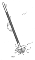
- FIG 1 illustrates a cable tie 1 according to a first embodiment of the invention.
- the tie 1 comprises a flexible strip 2 with teeth 20 over a portion of its length and a mounting body 3 connected to the flexible strip 2 at one of its ends.
- the mounting body 3 is illustrated more clearly in figure 2 , and comprises a flange 4, a core 5 dependent on the flange 4, a passage 6 for receiving the free end 22 of the flexible tape 2, a latch 7 dependent on the flange 4 and intended to engage in the teeth 20 of the flexible tape 2 when inserted into the passage 6 and a fixing device 8 also dependent on the flange 4 for engaging in a vehicle panel in order to fix the collar 1 to the panel.
- the teeth 20 have a pitch of a few millimeters, and for example a pitch of 1 mm for example to optimize the tightening.
- a pitch of 1 mm for example to optimize the tightening.
- any other pitch of teeth 20 can be implemented (for example 1.5 mm or 2 mm).
- the flange 4 has the shape of a truncated disc 40, which is connected at its top to the flexible ribbon 2 and which extends outwards towards the fixing device 8.
- a ribbon receiving channel 41 for receiving the flexible ribbon is formed in the flange 4, and extends radially from the passage 6.
- the core 5 describes a ribbon guide 51, which extends perpendicular to the ribbon receiving channel 41 formed in the flange 4.
- the ribbon guide 51 includes a chamfered upper portion 52 to accommodate a radius of curvature of the flexible ribbon 2.
- the passage 6 comprises an enlarged inlet 60 and an intermediate section 61 which is described between the ribbon guide 51 and the lock 7.
- the enlarged inlet 60 is provided to adapt to a radius of curvature of the flexible ribbon 2.
- the lock 7 comprises a locking arm 70, which depends on the flange 4 and which carries three locking teeth 71, 72, 73 to engage with the teeth 20 of the flexible strip 2.
- the locking teeth 71, 72, 73 have a pitch of a few millimeters, and for example a pitch of 1 mm for example to optimize the tightening.
- any other pitch of locking teeth can be implemented (for example 1.5 mm or 2 mm).
- the pitch of the teeth 20 of the flexible strip is identical to the pitch of the locking teeth 71, 72, 73. It can however be different or slightly different.
- the locking tooth 71 at the free end of the locking arm 70 extends from the locking arm 70 at an angle away from the flange 4.
- the intermediate locking tooth 72 extends at a similar angle, while the proximal locking tooth 73 projects at an angle that is nearly perpendicular to the locking arm 70.
- the latch 7 is connected to the mounting body 3 via a weakened region 74 describing a hinge around which the latch 7 is capable of pivoting.
- the locking arm 70 also includes the weakened region 74 which is for example a narrowed portion 74 between the proximal locking tooth 73 and its connection with the flange 4.
- the narrowed portion 74 describes a hinge about which the latch 7 is capable of pivoting.
- the narrowed portion 74 is described by a first recess 75, which extends into the locking arm 70 on the same side as the locking teeth 71, 72, 73, and a second recess 76, on the opposite side.
- the first recess 75 is narrow and deep, while the second recess 76 is shallow and wide.
- the thickness of the locking arm 70 in the narrowed portion 74 is reduced by more than half.
- the configuration of the tapered portion 74 in particular the presence of a first deeper recess 75 on the same side as the locking teeth 71, 72, 73, encourages the latch 7 to pivot towards the flexible ribbon 2 when a retracting force is applied, in use, to the flexible ribbon 2. This, in turn, urges the locking teeth 71, 72, 73 of the latch 7 to further engage the teeth 20 of the flexible ribbon 2.
- the angle of the locking tooth 71 at the free end of the locking arm 70 encourages this phenomenon, acting in concert with the configuration of the tapered portion 74 to reinforce it.
- the passage 6 comprises a chamfered transition 760 from the widened entrance 60 to the lock 7.
- the chamfered transition 760 is a connecting area 760 between the locking arm 70 and the tape receiving channel 41 of the flange 4.
- This connecting area 760 is for example chamfered (hereinafter also called chamfered connecting area 760), so as to describe a part of the widened entrance 60 of the passage 6. More precisely, the widened entrance 60 is described between the tape receiving channel 41, the chamfered connecting area 760 of the lock 7 and the chamfered upper part 52 of the tape guide 51. As more clearly illustrated in FIG. figure 3 , this allows the flexible ribbon 2 to form a more gradual bend 21 having a larger radius of curvature.
- the fastener 8 comprises a pair of opposing anchor legs 80 extending from a lower end of the core 5 towards the flange 4.
- the fastener 8 is configured to be inserted, once the flexible strip 2 is locked in place by the latch 7, into a hole in a vehicle body panel.
- the anchor legs 80 are then pushed towards each other until they emerge from the opposite side of the hole, where they snap into place to engage the panel.
- the distance between the anchor legs 80 and the flange 4 also causes the flange 4 to engage the panel and to urge the anchor legs 80 to engage the portion of the panel surrounding the hole.
- FIG. 4 shows a mounting body shows a mounting body 103 according to another example, in which similar features are identified by similar reference numerals incremented by 100 and will not be described further.
- the mounting body 103 according to this example differs from the mounting body 3 described above in that the narrowed portion 74 is omitted.
- FIG. 5 illustrates a mounting body 203 according to another example, in which similar features are identified by similar reference numerals incremented by 200 and will not be described further.
- the mounting body 203 according to this example differs from the mounting body 103 of the immediately preceding example in that the region 276 joining the locking arm 270 and the tape receiving channel 241 includes a stepped transition instead of a chamfered transition.
- the passage includes a step transition 276 from the widened entrance to the lock.
- FIG. 6 illustrates a mounting body 303 according to yet another example, in which similar features are identified by similar reference numerals incremented by 300 and will not be described further.
- the mounting body 303 according to this example differs from the mounting body 203 of the immediately preceding example in that a stepped transition region 376 joining the latch arm 370 and the tape receiving channel 241 includes an additional step.
- FIG. 7 illustrates a mounting body 403 according to yet another example, in which similar features are identified by similar reference numerals incremented by 400 and will not be described further.
- the mounting body 403 according to this example differs from the mounting body 103 of the previous example in that the chamfered upper portion 452 of the ribbon guide 451 is closer to the ribbon receiving channel 441.
- the opening 442 between the ribbon guide 451 and the flange 4 is reduced.
- this opening 442 is narrower than the free end 22 of the flexible ribbon 2 to prevent inadvertent insertion of the flexible ribbon 2 into this opening 442.
- FIG 8 illustrates a cable tie 1' according to a second embodiment of the invention.
- a cable tie 1' makes it possible to fix a cable bundle to a support.
- the tie 1' comprises a flexible strip 2' with teeth (not shown) over a portion of its length and a mounting body 3' connected to the flexible strip 2' at one of its ends 200' (hereinafter non-free end).
- the mounting body 3' is illustrated more clearly in figure 9 , and comprises a flange 4', a core 5' depending on the flange 4', a passage 6' for receiving the free end (not shown) of the flexible ribbon 2', a latch 7' depending on the flange 4' and intended to engage in the teeth of the flexible ribbon 2' when it is inserted into the passage 6' and a fixing device 8' (shown in figure 10 ) also dependent on the 4' flange to engage a vehicle panel to secure the 1' collar to the panel.
- the non-free end 200' of the flexible ribbon 2' is curved in order to allow centering relative to the mounting body 3' of one or more cable bundles when they are taken in and held by the flexible ribbon 2'.
- This curvature of the non-free end 200' of the flexible ribbon 2' thus makes it possible to optimize the radius of curvature of the free end of the flexible ribbon 2' when the latter is introduced into the inlet 60' of the passage 6'.
- the teeth of the flexible strip have a pitch of a few millimeters, and for example a pitch of 1 mm for example to optimize the tightening.
- any other tooth pitch can be implemented (for example 1.5 mm or 2 mm).
- the flange 4' has the shape of a truncated disc 40', which is connected at its top to the flexible strip 2' and which spreads outwards towards the fixing device.
- a strip receiving channel 41' allowing the reception of the flexible strip is formed in the flange 4', and extends radially from the passage 6'.
- the core 5' describes a ribbon guide 51', which extends perpendicular to the ribbon receiving channel 41' formed in the flange 4'.
- the passage 6' includes an inlet 60' and an intermediate section 61' which is described between the ribbon guide 51' and the lock 7'.
- the inlet 60' is provided to accommodate a bending radius of the flexible ribbon 2'.
- the lock 7' comprises a locking arm 70', which depends on the flange 4' and which carries three locking teeth 71', 72', 73' to engage with the teeth of the flexible strip 2'.
- the locking teeth 71', 72', 73' have a pitch of a few millimeters, and for example a pitch of 1 mm for example to optimize the tightening.
- any other pitch of locking teeth can be implemented (for example 1.5 mm or 2 mm).
- the pitch of the teeth of the flexible strip is identical to the pitch of the locking teeth 71', 72', 73'. It can however be different or slightly different.
- the locking tooth 71' at the free end of the locking arm 70' extends from the locking arm 70' at an angle away from the flange 4'.
- the intermediate locking tooth 72' extends at a similar angle, while the proximal locking tooth 73' projects at an angle that is nearly perpendicular to the locking arm 70'.
- the locking arm 70' is reinforced in thickness at the locking teeth 71', 72', 73'. This prevents deformation of the locking tooth 71' at the free end of the locking arm 70' when the locking arm is stressed.
- the locking teeth 71', 72', 73' of the locking arm 70' of the clamp according to the second embodiment are arranged at the end of the locking arm 70'.
- the locking teeth 71', 72', 73' of the locking arm 70' of the clamp according to the second embodiment are offset towards the end (distal end of the flange 4') of the locking arm.
- the locking teeth 71', 72', 73' of the locking arm 70' are lower than the locking teeth 71, 72, 73 of the locking arm 70 of the figure 2 for example. This allows to increase the holding or support exerted by the locking arm 70' compared to the support exerted by the locking arm of the figure 2 (first embodiment).
- the latch 7' is connected to the mounting body 3' via a weakened region 74' describing a hinge around which the latch 7' is capable of pivoting.
- the locking arm 70' also includes the weakened region 74' which is for example a narrowed portion 74' between the proximal locking tooth 73' and its connection with the flange 4'.
- the narrowed portion 74' describes a hinge about which the latch 7' is capable of pivoting.
- the narrowed portion 74' is described by a recess 76, which extends into the locking arm 70 on the side opposite to that carrying the locking teeth 71', 72', 73'.
- the recess 76 is for example shallow and wide.
- the thickness of the locking arm 70' in the narrowed portion 74' is reduced by less than half.
- the configuration of the tapered portion 74' encourages the latch 7' to pivot toward the flexible ribbon 2' when a retracting force is applied, in use, to the flexible ribbon 2'. This, in turn, causes the locking teeth 71', 72', 73' of the latch 7' to further engage the teeth of the flexible ribbon 2'.
- the angle of the locking tooth 71' at the free end of the locking arm 70' encourages this phenomenon, acting in concert with the configuration of the tapered portion 74' to reinforce it.
- the inlet 60' is described between the ribbon receiving channel 41', the latch 7' and the upper portion of the ribbon guide 51'. As more clearly illustrated in figure 9 , this allows the flexible ribbon 2' to form a more gradual bend 201' having a larger radius of curvature.
- the fastener 8' includes a pair of opposing anchor legs 80' extending from a lower end of the core 5' toward the flange 4'.
- the fastener 8' is configured to be inserted, after the flexible strip 2' is locked in place by the latch 7', into a hole in a vehicle body panel.
- the anchor legs 80' are then pushed toward each other until they emerge from the opposite side of the hole, where they snap into place to engage the panel.
- the distance between the anchor legs 80' and the flange 4' also causes the flange 4' to engage the panel and bias the anchor legs to engage the portion of the panel surrounding the hole.
- the mounting body 3 or 3' of the clamp 1 or 1' it is possible to implement on the mounting body 3 or 3' of the clamp 1 or 1', at least one rib 400' and preferably two ribs 400' on the top of the mounting body.
- the mounting body comprises two ribs arranged on either side of the non-free end of the flexible strip.
- Such ribs make it possible to improve the translational hold and to guide the flexible strip so as to optimize the overall radius of curvature of the flexible strip once taken in the mounting body.
- Such ribs also make it possible to increase the distance between the bundle and the entrance of the passage.
- THE figures 11 And 12 illustrate a 1" cable tie according to a third embodiment of the invention.
- a 1" cable tie makes it possible to attach a cable bundle to a support.
- a 1" clamp is for example suitable for a 6.5 mm diameter hole made in the support.
- the 1" clamp comprises a 2" flexible strip with teeth (not shown) over a portion of its length and a 3' mounting body connected to the 2" flexible strip at one of its ends 200" (hereinafter non-free end).
- the 3" mounting body comprises a 4" flange, a 5" core depending on the 4" flange, a 6" passage for receiving the free end (not shown) of the 2" flexible strip, a 7" lock depending on the 4" flange and intended to engage in the teeth of the 2" flexible strip when it is inserted into the 6" passage and an 8" fixing device (for example comprising deformable teeth or collars) also depending on the 4" flange for engaging in a vehicle panel in order to fix the 1" clamp to the panel.
- an 8" fixing device for example comprising deformable teeth or collars
- the 7" latch includes a 70" locking arm, which depends from the 4" flange and carries three 71", 72", 73" locking teeth to engage with the teeth of the 2" flexible ribbon.
- the 7" latch is connected to the 3" mounting body via a weakened region 74" describing a hinge about which the 7" latch is capable of pivoting.
Landscapes
- Engineering & Computer Science (AREA)
- General Engineering & Computer Science (AREA)
- Mechanical Engineering (AREA)
- Insertion Pins And Rivets (AREA)
- Clamps And Clips (AREA)
Description
- L'invention concerne le domaine des collier de serrage pour fixer un faisceau de câbles à un support. Plus précisément, mais pas exclusivement, cette invention concerne un collier de serrage pour fixer un faisceau de câbles à une carrosserie de véhicule.
- Les dispositifs conventionnels d'attache de câbles de ce type sont moulés intégralement à partir d'une résine synthétique. Le dispositif comprend généralement un long ruban flexible comportant des dents d'engagement sur au moins une partie de sa longueur, un corps définissant un passage pour l'insertion du ruban flexible à travers celui-ci et un verrou déformable associé au passage du corps pour engager les dents. Lors de l'utilisation, le ruban flexible est enroulé autour du faisceau de câbles et inséré dans le passage, jusqu'à ce que le faisceau de câbles soit étroitement entouré par le ruban flexible. Le verrou s'engage dans les dents du ruban flexible pour verrouiller le ruban flexible en place et empêcher son retrait du passage.
-
DE202016106524 etUS2008093511 ainsi queFR2790796 FR2901924 - La présente invention propose un perfectionnement à cette technologie.
- L'invention concerne un collier de serrage selon la revendication 1.
- La région de faiblesse permet au verrou d'être encouragé à se déformer d'une manière prédéterminée. Par exemple, la région de faiblesse peut être configurée pour encourager le verrou à pivoter vers le ruban flexible, de telle sorte qu'une force de rétraction appliquée, en cours d'utilisation, au ruban flexible lorsqu'il est engagé avec le verrou, pousse le verrou à s'engager davantage avec le ruban flexible.
- Selon un mode de réalisation de l'invention, le verrou comprend un bras de verrouillage dépendant du corps de montage avec au moins une dent de verrouillage pour s'engager avec les dents du ruban flexible et la région affaiblie est fournie par une partie rétrécie du bras de verrouillage. Selon un mode de réalisation de l'invention, le verrou peut comprendre un bras de verrouillage. Le bras de verrouillage peut dépendre du corps de montage. Le bras de verrouillage peut avoir au moins une dent de verrouillage, par exemple pour s'engager avec les dents du ruban flexible. L'au moins une dent de verrouillage peut se trouver au niveau ou à proximité d'une extrémité libre du bras de verrouillage. La dent de verrouillage peut faire saillie du bras de verrouillage à un angle tel qu'une force de rétraction appliquée, en utilisation, au ruban flexible lorsqu'il est engagée avec le verrou pousse le bras de verrouillage en prise supplémentaire avec le ruban flexible.
- Selon un mode de réalisation de l'invention, la dent de verrouillage peut faire saillie du bras de verrouillage à un angle tel qu'une force de rétraction appliquée, en utilisation, au ruban flexible lorsqu'il est engagée avec le verrou pousse le bras de verrouillage à s'engager davantage avec le ruban flexible. La dent de verrouillage peut faire saillie ou s'étendre à partir du bras de verrouillage dans une direction s'éloignant de la connexion entre le ruban flexible et le corps de montage. L'au moins une dent de verrouillage peut comprendre une pluralité de dents de verrouillage, par exemple trois dents de verrouillage, qui peuvent être espacées le long du bras de verrouillage.
- La région affaiblie peut être fournie par une partie rétrécie du bras de verrouillage. L'épaisseur du bras de verrouillage dans la partie rétrécie peut être réduite d'au moins un quart, de préférence d'au moins un tiers, par exemple d'environ ou d'au moins la moitié. Le bras de verrouillage peut comprendre un évidement sur au moins un de ses côtés.
- Selon un mode de réalisation de l'invention, le bras de verrouillage peut comprendre un évidement sur le même côté que les dents de verrouillage. Le bras de verrouillage peut comprendre un évidement sur son côté opposé aux dents de verrouillage. L'évidement du même côté que les dents de verrouillage peut être plus profond que l'évidement du côté opposé.
- La profondeur de l'évidement du même côté que les dents de verrouillage peut être d'au moins 20% de l'épaisseur du bras de verrouillage. La profondeur de l'évidement du même côté que les dents de verrouillage est de préférence d'au moins 30% de l'épaisseur du bras de verrouillage. La profondeur de l'évidement du même côté que les dents de verrouillage est de préférence au moins égale à 40% de l'épaisseur du bras de verrouillage. La profondeur de l'évidement du même côté que les dents de verrouillage peut représenter environ la moitié de l'épaisseur du bras de verrouillage.
- Selon un mode de réalisation de l'invention, la ou les dents de verrouillage est(sont) disposées au niveau de l'extrémité du bras de verrouillage.
- Selon un mode de réalisation de l'invention, le bras de verrouillage est renforcé en épaisseur au niveau des dents de verrouillage.
- Selon un mode de réalisation de l'invention, le ruban flexible présente une courbure en son extrémité non libre.
- Selon un mode de réalisation de l'invention, le passage comprend une entrée élargie pour s'adapter à un rayon de courbure du ruban flexible.
- L'entrée élargie permet donc une courbe plus graduelle que les cols conventionnels. Cela permet de rapprocher le faisceau de câbles au corps, et donc au support sur lequel le collier est monté.
- Selon un mode de réalisation de l'invention, le passage comprend une transition chanfreinée depuis l'entrée élargie vers le verrou.
- Le passage peut comprendre une transition, par exemple de l'entrée élargie et/ou vers le verrou. Le verrou ou le bras de verrouillage peut comprendre au moins une partie de la transition. Le corps de montage peut comprendre au moins une partie de la transition.
- Selon un mode de réalisation de l'invention, le passage comprend une transition par palier depuis l'entrée élargie vers le verrou.
- La transition peut être chanfreinée ou peut comprendre une partie chanfreinée. Le verrou peut être chanfreiné ou peut comprendre la partie chanfreinée, par exemple pour fournir au moins une partie de la transition. En outre, ou alternativement, le corps de montage peut être chanfreiné ou comprendre la partie chanfreinée, par exemple pour fournir au moins une partie de la transition.
- La transition peut être une transition par palier ou peut être étagée ou peut comprendre une partie étagée. Le verrou peut comprendre la transition par palier. Le verrou peut être étagé ou peut comprendre la partie étagée, par exemple pour fournir au moins une partie de la transition. En outre ou alternativement, le corps de montage peut être une transition par palier. Le corps de montage peut être étagé ou comprendre la partie étagée, par exemple pour fournir au moins une partie de la transition.
- Selon un mode de réalisation de l'invention, lequel le corps de montage comprend une bride et le passage est décrit entre le verrou et un guide-ruban, le guide-ruban étant espacé de la bride pour créer une ouverture entre eux qui est plus étroite que l'extrémité libre du ruban flexible.
- Le guide-ruban et le verrou peuvent décrire au moins une partie du passage entre eux. Le guide-ruban peut comprendre la transition ou une autre transition, par exemple de l'entrée élargie et/ou à proximité de l'entrée élargie et/ou vers le verrou. La transition du guide-ruban peut être chanfreinée ou le guide-ruban peut comprendre une partie chanfreinée. La transition du guide-ruban peut être étagée ou le guide-ruban peut comprendre une partie étagée.
- Le corps de montage peut comprendre une bride. La bride peut être effilée, conique ou tronconique. La bride peut s'effiler, par exemple vers l'extérieur, depuis une ouverture du passage vers le verrou et/ou vers le dispositif de fixation. La bride peut s'effiler, par exemple vers l'extérieur, depuis sa connexion avec le ruban flexible vers le verrou et/ou vers le dispositif de fixation.
- Le canal de réception peut être former dans la bride. Le canal de réception du ruban flexible peut décrire au moins une partie de l'entrée élargie du passage.
- Le guide-ruban peut être espacé de la bride pour créer une ouverture entre eux. L'ouverture peut être plus étroite qu'une extrémité libre du ruban flexible.
- Le dispositif de fixation peut comprendre un ou plusieurs pieds d'ancrage. Le ou les pieds d'ancrage peuvent comprendre une paire de pieds d'ancrage opposés. Le corps de montage peut comprendre un noyau, par exemple à partir duquel s'étendent les pieds d'ancrage. Les pieds d'ancrage peuvent s'étendre vers le haut et/ou vers l'extérieur, par exemple à partir d'une extrémité inférieure du noyau et/ou vers la bride. Le noyau peut dépendre de la bride. Le noyau peut comprendre le guide-ruban. Le noyau peut comprendre un dispositif de centrage, par exemple une paire de coins opposés.
- Le dispositif de fixation peut être configuré pour être inséré, en cours d'utilisation, dans un trou d'un panneau de carrosserie de véhicule, par exemple de telle sorte que les pieds d'ancrage soient poussés l'un vers l'autre jusqu'à ce qu'ils émergent du côté opposé du trou, où ils s'enclenchent en place pour s'engager dans le panneau. Le collier peut être configuré de telle sorte que l'insertion, en cours d'utilisation, du dispositif de fixation dans le trou de la carrosserie du véhicule amène la bride à s'engager dans le panneau et à solliciter les pieds d'ancrage pour qu'ils s'engagent dans la partie du panneau entourant le trou.
- Le ou chaque pied d'ancrage peut comprendre au moins un épaulement, par exemple pour s'engager dans une partie de panneau entourant un trou dans lequel le dispositif de fixation est inséré. L'au moins un épaulement peut comprendre deux épaulements ou plus, qui peuvent être prévus dans une configuration en escalier. En variante, le dispositif de fixation peut comprendre deux ou plusieurs pieds d'ancrage espacés sur la longueur ou dans la direction d'insertion du dispositif de fixation. Le dispositif de fixation peut comprendre pieds d'ancrage en forme de sapin.
- Ces configurations permettent au dispositif de fixation d'être inséré dans un engagement plus robuste avec le panneau et/ou de s'adapter à des panneaux d'épaisseurs différentes.
- Selon un mode de réalisation de l'invention, le corps de montage comprend deux nervures disposées de part et d'autre de l'extrémité non libre du ruban flexible.
- Selon un mode de réalisation de l'invention, le passage comprend une entrée élargie pour s'adapter à un rayon de courbure du ruban flexible.
- L'entrée élargie permet donc une courbe plus graduelle que les cols conventionnels. Cela permet de rapprocher le faisceau de câbles au corps, et donc au support sur lequel le collier est monté.
- Selon l'invention dans au moins un de ses modes de réalisation, le verrou est relié au corps de montage via une région affaiblie décrivant une charnière autour de laquelle le verrou est capable de pivoter.
- La région de faiblesse permet au verrou d'être encouragé à se déformer d'une manière prédéterminée. Par exemple, la région de faiblesse peut être configurée pour encourager le verrou à pivoter vers le ruban flexible, de telle sorte qu'une force de rétraction appliquée, en cours d'utilisation, au ruban flexible lorsqu'il est engagé avec le verrou, pousse le verrou à s'engager davantage avec le ruban flexible.
- Selon un mode de réalisation de l'invention, le verrou comprend un bras de verrouillage dépendant du corps de montage avec au moins une dent de verrouillage pour s'engager avec les dents du ruban flexible et la région affaiblie est fournie par une partie rétrécie du bras de verrouillage. Selon un mode de réalisation de l'invention, le verrou peut comprendre un bras de verrouillage. Le bras de verrouillage peut dépendre du corps de montage. Le bras de verrouillage peut avoir au moins une dent de verrouillage, par exemple pour s'engager avec les dents du ruban flexible. L'au moins une dent de verrouillage peut se trouver au niveau ou à proximité d'une extrémité libre du bras de verrouillage. La dent de verrouillage peut faire saillie du bras de verrouillage à un angle tel qu'une force de rétraction appliquée, en utilisation, au ruban flexible lorsqu'il est engagée avec le verrou pousse le bras de verrouillage en prise supplémentaire avec le ruban flexible.
- Selon un mode de réalisation de l'invention, la dent de verrouillage peut faire saillie du bras de verrouillage à un angle tel qu'une force de rétraction appliquée, en utilisation, au ruban flexible lorsqu'il est engagée avec le verrou pousse le bras de verrouillage à s'engager davantage avec le ruban flexible. La dent de verrouillage peut faire saillie ou s'étendre à partir du bras de verrouillage dans une direction s'éloignant de la connexion entre le ruban flexible et le corps de montage. L'au moins une dent de verrouillage peut comprendre une pluralité de dents de verrouillage, par exemple trois dents de verrouillage, qui peuvent être espacées le long du bras de verrouillage.
- La région affaiblie peut être fournie par une partie rétrécie du bras de verrouillage. L'épaisseur du bras de verrouillage dans la partie rétrécie peut être réduite d'au moins un quart, de préférence d'au moins un tiers, par exemple d'environ ou d'au moins la moitié. Le bras de verrouillage peut comprendre un évidement sur au moins un de ses côtés.
- Selon un mode de réalisation de l'invention, le bras de verrouillage peut comprendre un évidement sur le même côté que les dents de verrouillage. Le bras de verrouillage peut comprendre un évidement sur son côté opposé aux dents de verrouillage. L'évidement du même côté que les dents de verrouillage peut être plus profond que l'évidement du côté opposé.
- La profondeur de l'évidement du même côté que les dents de verrouillage peut être d'au moins 20% de l'épaisseur du bras de verrouillage. La profondeur de l'évidement du même côté que les dents de verrouillage est de préférence d'au moins 30% de l'épaisseur du bras de verrouillage. La profondeur de l'évidement du même côté que les dents de verrouillage est de préférence au moins égale à 40% de l'épaisseur du bras de verrouillage. La profondeur de l'évidement du même côté que les dents de verrouillage peut représenter environ la moitié de l'épaisseur du bras de verrouillage.
- Selon un mode de réalisation de l'invention, la ou les dents de verrouillage est(sont) disposées au niveau de l'extrémité du bras de verrouillage.
- Selon un mode de réalisation de l'invention, le bras de verrouillage est renforcé en épaisseur au niveau des dents de verrouillage.
- Selon un mode de réalisation de l'invention, le ruban flexible présente une courbure en son extrémité non libre.
- Selon un mode de réalisation de l'invention, le passage comprend une transition chanfreinée depuis l'entrée élargie vers le verrou.
- Le passage peut comprendre une transition, par exemple de l'entrée élargie et/ou vers le verrou. Le verrou ou le bras de verrouillage peut comprendre au moins une partie de la transition. Le corps de montage peut comprendre au moins une partie de la transition.
- Selon un mode de réalisation de l'invention, le passage comprend une transition par palier depuis l'entrée élargie vers le verrou.
- La transition peut être chanfreinée ou peut comprendre une partie chanfreinée. Le verrou peut être chanfreiné ou peut comprendre la partie chanfreinée, par exemple pour fournir au moins une partie de la transition. En outre, ou alternativement, le corps de montage peut être chanfreiné ou comprendre la partie chanfreinée, par exemple pour fournir au moins une partie de la transition.
- La transition peut être une transition par palier ou peut être étagée ou peut comprendre une partie étagée. Le verrou peut comprendre la transition par palier. Le verrou peut être étagé ou peut comprendre la partie étagée, par exemple pour fournir au moins une partie de la transition. En outre ou alternativement, le corps de montage peut être une transition par palier. Le corps de montage peut être étagé ou comprendre la partie étagée, par exemple pour fournir au moins une partie de la transition.
- Selon un mode de réalisation de l'invention, lequel le corps de montage comprend une bride et le passage est décrit entre le verrou et un guide-ruban, le guide-ruban étant espacé de la bride pour créer une ouverture entre eux qui est plus étroite que l'extrémité libre du ruban flexible.
- Le collier ou le corps de montage peut comprendre un guide-ruban. Au moins une partie du guide-ruban peut décrire au moins une partie du passage. Le guide-ruban et le verrou peuvent décrire au moins une partie du passage entre eux. Le guide-ruban peut comprendre la transition ou une autre transition, par exemple de l'entrée élargie et/ou à proximité de l'entrée élargie et/ou vers le verrou. La transition du guide-ruban peut être chanfreinée ou le guide-ruban peut comprendre une partie chanfreinée. La transition du guide-ruban peut être étagée ou le guide-ruban peut comprendre une partie étagée.
- Le corps de montage peut comprendre une bride. La bride peut être effilée, conique ou tronconique. La bride peut s'effiler, par exemple vers l'extérieur, depuis une ouverture du passage vers le verrou et/ou vers le dispositif de fixation. La bride peut s'effiler, par exemple vers l'extérieur, depuis sa connexion avec le ruban flexible vers le verrou et/ou vers le dispositif de fixation.
- Le corps de montage peut comprendre un canal de réception pour le ruban flexible. Le canal de réception peut être former dans la bride. Le canal de réception peut être perpendiculaire au guide-ruban. Le canal de réception du ruban flexible peut décrire au moins une partie de l'entrée élargie du passage.
- Le guide-ruban peut être espacé de la bride pour créer une ouverture entre eux. L'ouverture peut être plus étroite qu'une extrémité libre du ruban flexible.
- Le dispositif de fixation peut comprendre un ou plusieurs pieds d'ancrage. Le ou les pieds d'ancrage peuvent comprendre une paire de pieds d'ancrage opposés. Le corps de montage peut comprendre un noyau, par exemple à partir duquel s'étendent les pieds d'ancrage. Les pieds d'ancrage peuvent s'étendre vers le haut et/ou vers l'extérieur, par exemple à partir d'une extrémité inférieure du noyau et/ou vers la bride. Le noyau peut dépendre de la bride. Le noyau peut comprendre le guide-ruban. Le noyau peut comprendre un dispositif de centrage, par exemple une paire de coins opposés.
- Le dispositif de fixation peut être configuré pour être inséré, en cours d'utilisation, dans un trou d'un panneau de carrosserie de véhicule, par exemple de telle sorte que les pieds d'ancrage soient poussés l'un vers l'autre jusqu'à ce qu'ils émergent du côté opposé du trou, où ils s'enclenchent en place pour s'engager dans le panneau. Le collier peut être configuré de telle sorte que l'insertion, en cours d'utilisation, du dispositif de fixation dans le trou de la carrosserie du véhicule amène la bride à s'engager dans le panneau et à solliciter les pieds d'ancrage pour qu'ils s'engagent dans la partie du panneau entourant le trou.
- Le ou chaque pied d'ancrage peut comprendre au moins un épaulement, par exemple pour s'engager dans une partie de panneau entourant un trou dans lequel le dispositif de fixation est inséré. L'au moins un épaulement peut comprendre deux épaulements ou plus, qui peuvent être prévus dans une configuration en escalier. En variante, le dispositif de fixation peut comprendre deux ou plusieurs pieds d'ancrage espacés sur la longueur ou dans la direction d'insertion du dispositif de fixation. Le dispositif de fixation peut comprendre pieds d'ancrage en forme de sapin.
- Ces configurations permettent au dispositif de fixation d'être inséré dans un engagement plus robuste avec le panneau et/ou de s'adapter à des panneaux d'épaisseurs différentes.
- Selon un mode de réalisation de l'invention, le corps de montage comprend deux nervures disposées de part et d'autre de l'extrémité non libre du ruban flexible.
- Pour éviter tout doute, toutes les caractéristiques décrites ici s'appliquent également à tout aspect de l'invention.
- D'autres caractéristiques et avantages de l'invention apparaitront au cours de la lecture de la description détaillée qui va suivre pour la compréhension de laquelle on se reportera aux dessins annexés dans lesquels :
- [
Fig. 1 ] lafigure 1 est une vue en perspective d'un collier selon un premier mode de réalisation de l'invention ; - [
Fig. 2 ] lafigure 2 est une vue en coupe du corps de montage du collier de lafigure 1 ; - [
Fig. 3 ] lafigure 3 est une vue similaire à celle de lafigure 2 montrant le rayon de courbure du ruban flexible à l'entrée du passage ; - [
Fig. 4 ] lafigure 4 est une vue en coupe d'un autre corps de montage ; - [
Fig. 5 ] lafigure 5 est une vue en coupe d'un autre corps de montage alternatif ; - [
Fig. 6 ] lafigure 6 est une vue en coupe d'un autre corps de montage alternatif ; - [
Fig. 7 ] lafigure 7 est une vue en coupe d'un autre corps de montage alternatif ; - [
Fig. 8 ] lafigure 8 est une vue en coupe d'un corps de montage d'un collier selon un second mode de réalisation de l'invention ; - [
Fig. 9 ] lafigure 9 est une vue similaire à celle de lafigure 8 montrant le rayon de courbure du ruban flexible à l'entrée du passage ; - [
Fig. 10 ] lafigure 10 illustre le dispositif de fixation du collier de lafigure 8 . - La
figure 1 illustre un collier de serrage 1 selon un premier mode de réalisation de l'invention. Un tel collier de serrage 1 permet de fixer un faisceau de câbles à un support. Le collier 1 comprend un ruban flexible 2 avec des dents 20 sur une partie de sa longueur et un corps de montage 3 relié au ruban flexible 2 à l'une de ses extrémités. Le corps de montage 3 est illustré plus clairement à lafigure 2 , et comprend une bride 4, un noyau 5 dépendant de la bride 4, un passage 6 pour recevoir l'extrémité libre 22 du ruban flexible 2, un verrou 7 dépendant de la bride 4 et destiné à s'engager dans les dents 20 du ruban flexible 2 lorsqu'elle est insérée dans le passage 6 et un dispositif de fixation 8 aussi dépendant de la bride 4 pour s'engager dans un panneau de véhicule afin de fixer le collier 1 au panneau. - Par exemple, les dents 20 présentent un pas de quelques millimètres, et par exemple un pas de 1 mm par exemple pour optimiser le serrage. Bien entendu tout autre pas de dents 20 peut être mis en oeuvre (par exemple 1,5mm ou 2 mm).
- La bride 4 a la forme d'un disque tronconique 40, qui est relié à son sommet au ruban flexible 2 et qui s'écarte vers l'extérieur en direction du dispositif de fixation 8. Un canal de réception de ruban 41 permettant la réception du ruban flexible est formé dans la bride 4, et s'étend radialement à partir du passage 6.
- Le noyau 5 décrit un guide de ruban 51, qui s'étend de façon perpendiculaire par rapport au canal de réception de ruban 41 formé dans la bride 4. Dans cet exemple, le guide-ruban 51 comprend une partie supérieur chanfreiné 52 pour s'adapter à un rayon de courbure du ruban flexible 2.
- Le passage 6 comprend une entrée élargie 60 et une section intermédiaire 61 qui est décrite entre le guide-ruban 51 et le verrou 7. L'entrée élargie 60 est prévue pour s'adapter à un rayon de courbure du ruban flexible 2.
- Le verrou 7 comprend un bras de verrouillage 70, qui dépend de la bride 4 et qui porte trois dents de verrouillage 71, 72, 73 pour s'engager avec les dents 20 du ruban flexible 2. Ainsi, par exemple, les dents de verrouillage 71, 72, 73 présentent un pas de quelques millimètres, et par exemple un pas de 1 mm par exemple pour optimiser le serrage. Bien entendu tout autre pas de dents de verrouillage peut être mis en oeuvre (par exemple 1,5mm ou 2 mm). Avantageusement, le pas des dents 20 du ruban flexible est identique au pas des dents de verrouillage 71, 72, 73. Il peut cependant être différent ou légèrement différent.
- La dent de verrouillage 71 à l'extrémité libre du bras de verrouillage 70 s'étend à partir du bras de verrouillage 70 selon un angle, en s'éloignant de la bride 4. La dent de verrouillage intermédiaire 72 s'étend selon un angle similaire, tandis que la dent de verrouillage proximale 73 fait saillie selon un angle qui est presque perpendiculaire au bras de verrouillage 70.
- Selon un mode de réalisation de l'invention, le verrou 7 est relié au corps de montage 3 via une région affaiblie 74 décrivant une charnière autour de laquelle le verrou 7 est capable de pivoter.
- Ainsi, par exemple, le bras de verrouillage 70 comprend également la région affaiblie 74 qui est par exemple une partie rétrécie 74 entre la dent de verrouillage proximale 73 et sa connexion avec la bride 4. Par exemple, la partie rétrécie 74 décrit une charnière autour de laquelle le verrou 7 est capable de pivoter. La partie rétrécie 74 est décrite par un premier évidement 75, qui s'étend dans le bras de verrouillage 70 du même côté que les dents de verrouillage 71, 72, 73, et un second évidement 76, du côté opposé. Le premier évidement 75 est étroit et profond, tandis que le second évidement 76 est peu profond et large. L'épaisseur du bras de verrouillage 70 dans la partie rétrécie 74 est réduite de plus de la moitié.
- La configuration de la partie rétrécie 74, en particulier la présence d'un premier évidement plus profond 75 du même côté que les dents de verrouillage 71, 72, 73, encourage le verrou 7 à pivoter vers le ruban flexible 2 lorsqu'une force de rétraction est appliquée, en service, au ruban flexible 2. Ceci, à son tour, pousse les dents de verrouillage 71, 72, 73 du verrou 7 à s'engager davantage avec les dents 20 du ruban flexible 2. L'angle de la dent de verrouillage 71 à l'extrémité libre du bras de verrouillage 70 encourage ce phénomène, agissant de concert avec la configuration de la partie rétrécie 74 pour le renforcer.
- Selon un mode de réalisation de l'invention, le passage 6 comprend une transition chanfreinée 760 depuis l'entrée élargie 60 vers le verrou 7.
- Par exemple, la transition chanfreinée 760 est une zone de liaison 760 entre le bras de verrouillage 70 et le canal de réception de ruban 41 de la bride 4. Cette zone de liaison 760 est par exemple chanfreinée (ci-après également appelée zone de liaison chanfreinée 760), de manière à décrire une partie de l'entrée élargie 60 du passage 6. Plus précisément, l'entrée élargie 60 est décrite entre le canal de réception de ruban 41, la zone de liaison chanfreinée 760 du verrou 7 et la partie supérieur chanfreiné 52 du guide-ruban 51. Comme l'illustre plus clairement la
figure 3 , cela permet au ruban flexible 2 de former un coude 21 plus graduel ayant un plus grand rayon de courbure. - Le dispositif de fixation 8 comprend une paire de pieds d'ancrage 80 opposés, qui s'étendent depuis une extrémité inférieure du noyau 5, vers la bride 4. Le dispositif de fixation 8 est configuré pour être inséré, une fois le ruban flexible 2 verrouillé en place par le verrou 7, dans un trou d'un panneau de carrosserie de véhicule. Les pieds d'ancrage 80 sont alors poussés l'un vers l'autre jusqu'à ce qu'ils émergent du côté opposé du trou, où ils s'enclenchent en place pour s'engager dans le panneau. La distance entre les pieds d'ancrage 80 et la bride 4 amène également la bride 4 à s'engager dans le panneau et à solliciter les pieds d'ancrage 80 pour qu'ils s'engagent dans la partie du panneau entourant le trou.
- La
figure 4 montre un corps de montage montre un corps de montage 103 selon un autre exemple, dans lequel les caractéristiques similaires sont identifiées par des références similaires incrémentées par 100 et ne seront pas décrites davantage. Le corps de montage 103 selon cet exemple diffère du corps de montage 3 décrit ci-dessus en ce que la partie rétrécie 74 est omise. - La
figure 5 illustre un corps de montage 203 selon un autre exemple, dans lequel les caractéristiques similaires sont identifiées par des références similaires incrémentées par 200 et ne seront pas décrites davantage. Le corps de montage 203 selon cet exemple diffère du corps de montage 103 de l'exemple immédiatement précédent en ce que la région 276 joignant le bras de verrouillage 270 et le canal de réception de ruban 241 comprend une transition par palier au lieu d'une transition chanfreinée. - Ainsi, par exemple, le passage comprend une transition par palier 276 depuis l'entrée élargie vers le verrou.
- La
figure 6 illustre un corps de montage 303 selon encore un autre exemple, dans lequel les caractéristiques similaires sont identifiées par des références similaires incrémentées par 300 et ne seront pas décrites davantage. Le corps de montage 303 selon cet exemple diffère du corps de montage 203 de l'exemple immédiatement précédent en ce qu'une région de transition par palier 376 joignant le bras de verrouillage 370 et le canal de réception de ruban 241 comprend une étage supplémentaire. - La
figure 7 illustre un corps de montage 403 selon encore un autre exemple, dans lequel les caractéristiques similaires sont identifiées par des références similaires incrémentées par 400 et ne seront pas décrites davantage. Le corps de montage 403 selon cet exemple diffère du corps de montage 103 de l'exemple précédent en ce que la partie supérieur chanfreiné 452 du guide-ruban 451 est plus proche du canal de réception de ruban 441. Ainsi, l'ouverture 442 entre le guide-ruban 451 et la bride 4 est réduite. Dans cet exemple, cette ouverture 442 est plus étroite que l'extrémité libre 22 du ruban flexible 2 pour empêcher l'insertion par inadvertance du ruban flexible 2 dans cette ouverture 442. - La
figure 8 illustre un collier de serrage 1' selon un second mode de réalisation de l'invention. Un tel collier de serrage 1' permet de fixer un faisceau de câbles à un support. Le collier 1' comprend un ruban flexible 2' avec des dents (non représentées) sur une partie de sa longueur et un corps de montage 3' relié au ruban flexible 2' à l'une de ses extrémités 200' (ci-après extrémité non libre). Le corps de montage 3' est illustré plus clairement à lafigure 9 , et comprend une bride 4', un noyau 5' dépendant de la bride 4', un passage 6' pour recevoir l'extrémité libre (non représentée) du ruban flexible 2', un verrou 7' dépendant de la bride 4' et destiné à s'engager dans les dents du ruban flexible 2' lorsqu'elle est insérée dans le passage 6' et un dispositif de fixation 8' (représenté enfigure 10 ) aussi dépendant de la bride 4' pour s'engager dans un panneau de véhicule afin de fixer le collier 1' au panneau. - Par exemple, l'extrémité non libre 200' du ruban flexible 2' est courbée afin de permettre un centrage par rapport au corps de montage 3' d'un ou plusieurs faisceau(x) de câbles lorsqu'il(s) sont pris dans et maintenus par le ruban flexible 2'. Cette courbure de l'extrémité non libre 200' du ruban flexible 2' permet ainsi d'optimiser le rayon de courbure de l'extrémité libre du ruban flexible 2' lorsque celle-ci est introduite dans l'entrée 60' du passage 6'.
- Par exemple, les dents du ruban flexible présentent un pas de quelques millimètres, et par exemple un pas de 1 mm par exemple pour optimiser le serrage. Bien entendu tout autre pas de dents peut être mis en oeuvre (par exemple 1,5mm ou 2 mm). La bride 4' a la forme d'un disque tronconique 40', qui est relié à son sommet au ruban flexible 2' et qui s'écarte vers l'extérieur en direction du dispositif de fixation. Un canal de réception de ruban 41' permettant la réception du ruban flexible est formé dans la bride 4', et s'étend radialement à partir du passage 6'.
- Le noyau 5' décrit un guide de ruban 51', qui s'étend de façon perpendiculaire par rapport au canal de réception de ruban 41' formé dans la bride 4'.
- Le passage 6' comprend une entrée 60' et une section intermédiaire 61' qui est décrite entre le guide-ruban 51' et le verrou 7'. L'entrée 60' est prévue pour s'adapter à un rayon de courbure du ruban flexible 2'.
- Le verrou 7' comprend un bras de verrouillage 70', qui dépend de la bride 4' et qui porte trois dents de verrouillage 71', 72', 73' pour s'engager avec les dents du ruban flexible 2'. Ainsi, par exemple, les dents de verrouillage 71', 72', 73' présentent un pas de quelques millimètres, et par exemple un pas de 1 mm par exemple pour optimiser le serrage. Bien entendu tout autre pas de dents de verrouillage peut être mis en oeuvre (par exemple 1,5mm ou 2 mm). Avantageusement, le pas des dents du ruban flexible est identique au pas des dents de verrouillage 71', 72', 73'. Il peut cependant être différent ou légèrement différent.
- La dent de verrouillage 71' à l'extrémité libre du bras de verrouillage 70' s'étend à partir du bras de verrouillage 70' selon un angle, en s'éloignant de la bride 4'. La dent de verrouillage intermédiaire 72' s'étend selon un angle similaire, tandis que la dent de verrouillage proximale 73' fait saillie selon un angle qui est presque perpendiculaire au bras de verrouillage 70'.
- Par exemple, le bras de verrouillage 70' est renforcé en épaisseur au niveau des dents de verrouillage 71', 72', 73'. Ceci permet d'éviter la déformation la dent de verrouillage 71' à l'extrémité libre du bras de verrouillage 70' lorsque que le bras de verrouillage est mis sous contrainte.
- Par exemple, les dents de verrouillage 71', 72', 73' du bras de verrouillage 70' du collier de serrage selon le second mode de réalisation sont disposées au niveau de l'extrémité du bras de verrouillage 70'.
- Ainsi, par rapport au premier mode de réalisation notamment des
figures 1 et2 , les dents de verrouillage 71', 72', 73' du bras de verrouillage 70' du collier de serrage selon le second mode de réalisation sont décalée vers l'extrémité (extrémité distale de la bride 4') du bras de verrouillage. Sur lafigure 8 , les dents de verrouillage 71', 72', 73' du bras de verrouillage 70' sont plus basses que les dents de verrouillage 71, 72, 73 du bras de verrouillage 70 de lafigure 2 par exemple. Ceci permet d'augmenter la tenue ou le maintien exercé par le bras de verrouillage 70' comparé au maintien exercé par le bras de verrouillage de lafigure 2 (premier mode de réalisation). - Selon un mode de réalisation de l'invention, le verrou 7' est relié au corps de montage 3' via une région affaiblie 74' décrivant une charnière autour de laquelle le verrou 7' est capable de pivoter.
- Ainsi, par exemple, le bras de verrouillage 70' comprend également la région affaiblie 74' qui est par exemple une partie rétrécie 74' entre la dent de verrouillage proximale 73' et sa connexion avec la bride 4'. Par exemple, la partie rétrécie 74' décrit une charnière autour de laquelle le verrou 7' est capable de pivoter. La partie rétrécie 74' est décrite par un évidement 76,qui s'étend dans le bras de verrouillage 70 du côté opposé à celui portant les dents de verrouillage 71', 72', 73'. L'évidement 76 est par exemple peu profond et large. Par exemple, l'épaisseur du bras de verrouillage 70' dans la partie rétrécie 74' est réduite de moins de la moitié.
- La configuration de la partie rétrécie 74', en particulier la présence de l'évidement 76' encourage le verrou 7' à pivoter vers le ruban flexible 2' lorsqu'une force de rétraction est appliquée, en service, au ruban flexible 2'. Ceci, à son tour, pousse les dents de verrouillage 71', 72', 73' du verrou 7' à s'engager davantage avec les dents du ruban flexible 2'. L'angle de la dent de verrouillage 71' à l'extrémité libre du bras de verrouillage 70' encourage ce phénomène, agissant de concert avec la configuration de la partie rétrécie 74' pour le renforcer.
- Plus précisément, l'entrée 60' est décrite entre le canal de réception de ruban 41', le verrou 7' et la partie supérieure du guide-ruban 51'. Comme l'illustre plus clairement la
figure 9 , cela permet au ruban flexible 2' de former un coude 201' plus graduel ayant un plus grand rayon de courbure. - Par exemple, le dispositif de fixation 8' comprend une paire de pieds d'ancrage opposés 80', qui s'étendent depuis une extrémité inférieure du noyau 5', vers la bride 4'. Le dispositif de fixation 8' est configuré pour être inséré, une fois le ruban flexible 2' verrouillé en place par le verrou 7', dans un trou d'un panneau de carrosserie de véhicule. Les pieds d'ancrage 80' sont alors poussés l'un vers l'autre jusqu'à ce qu'ils émergent du côté opposé du trou, où ils s'enclenchent en place pour s'engager dans le panneau. La distance entre les pieds d'ancrage 80' et la bride 4' amène également la bride 4' à s'engager dans le panneau et à solliciter les pieds d'ancrage pour qu'ils s'engagent dans la partie du panneau entourant le trou.
- Tel qu'illustré par la
figure 10 , on peut mettre en oeuvre sur le corps de montage 3 ou 3' du collier de serrage 1 ou 1', au moins une nervure 400' et préférentiellement deux nervures 400' sur le dessus du corps de montage. Par exemple, le corps de montage comprend deux nervures disposées de part et d'autre de l'extrémité non libre du ruban flexible. De tels nervures permettent d'améliorer la tenue en translation et de guider le ruban flexible de sorte à optimiser le rayon de courbure global du ruban flexible une fois pris dans le corps de montage. De tels nervures Permettent également d'augmenter la distance entre le faisceau et l'entrée du passage. - Les
figures 11 et12 illustrent un collier de serrage 1" selon un troisième mode de réalisation de l'invention. Un tel collier de serrage 1" permet de fixer un faisceau de câbles à un support. Un tel collier de serrage 1" est par exemple adapté pour un trou de diamètre 6,5mm réalisé dans le support. Le collier 1" comprend un ruban flexible 2" avec des dents (non représentées) sur une partie de sa longueur et un corps de montage 3' relié au ruban flexible 2" à l'une de ses extrémités 200" (ci-après extrémité non libre). Le corps de montage 3" comprend une bride 4", un noyau 5" dépendant de la bride 4", un passage 6" pour recevoir l'extrémité libre (non représentée) du ruban flexible 2", un verrou 7" dépendant de la bride 4" et destiné à s'engager dans les dents du ruban flexible 2" lorsqu'elle est insérée dans le passage 6" et un dispositif de fixation 8" (par exemple comprenant des dents ou des collerettes déformables) aussi dépendant de la bride 4" pour s'engager dans un panneau de véhicule afin de fixer le collier 1" au panneau. - Le verrou 7" comprend un bras de verrouillage 70", qui dépend de la bride 4" et qui porte trois dents de verrouillage 71", 72", 73" pour s'engager avec les dents du ruban flexible 2".
- Selon un mode de réalisation de l'invention, le verrou 7" est relié au corps de montage 3" via une région affaiblie 74" décrivant une charnière autour de laquelle le verrou 7" est capable de pivoter.
- L'homme du métier appréciera que plusieurs variantes des modes de réalisation précités soient envisageables sans sortir du cadre de l'invention.
Claims (13)
- Un collier de serrage (1) pour fixer un faisceau de câbles à un support, le collier comprenant :un ruban flexible (2) avec des dents (20) sur au moins une partie de sa longueur;un corps de montage (3) relié au ruban flexible (2) à l'une de ses extrémités, ci-après extrémité non libre, et comprenant un passage (6) pour recevoir l'autre extrémité du ruban flexible (2), ci-après extrémité libre (22) ;un verrou (7) dépendant du corps de montage (3) et destiné à s'engager dans les dents (20) du ruban flexible (2) lorsqu'elle est insérée dans le passage (6) ; etun dispositif de fixation (8) dépendant du corps de montage (3) pour s'engager dans un panneau de véhicule afin de fixer le collier (1) au panneau,dans lequel :le verrou (7) est relié au corps de montage (3) via une région affaiblie (74, 74', 74") décrivant une charnière autour de laquelle le verrou (7) est capable de pivoter ; etle corps de montage (3) comprend un guide-ruban décrivant au moins une partie du passage;caractérisé en ce que le corps de montage comprend un canal de réception pour le ruban flexible qui est perpendiculaire au guide-ruban.
- Collier de serrage selon l'une quelconque des revendications précédentes, dans lequel le verrou (7) comprend un bras de verrouillage (70) dépendant du corps de montage (3) avec au moins une dent de verrouillage (71, 72, 73) pour s'engager avec les dents (20) du ruban flexible (2) et la région affaiblie (74) est fournie par une partie rétrécie du bras de verrouillage (70).
- Collier de serrage selon la revendication 2, dans lequel la dent de verrouillage (71, 72, 73) fait saillie du bras de verrouillage (70) à un angle tel qu'une force de rétraction appliquée, en utilisation, au ruban flexible (2) lorsqu'il est engagé avec le verrou (7) pousse le bras de verrouillage (70) en prise supplémentaire avec le ruban flexible (2).
- Collier de serrage selon la revendication 3, dans lequel le bras de verrouillage (70) comprend un évidement (75) sur le même côté que les dents de verrouillage.
- Collier de serrage selon l'une quelconque des revendications 3 et 4, caractérisé en ce que le bras de verrouillage comprend un évidement (76) sur son côté opposé aux dents de verrouillage.
- Collier de serrage selon l'une quelconque des revendications 2 à 5, caractérisé en ce que la ou les dents de verrouillage est(sont) disposées au niveau de l'extrémité du bras de verrouillage (70').
- Collier de serrage selon l'une quelconque des revendications 2 à 5, caractérisé en ce que le bras de verrouillage (70') est renforcé en épaisseur au niveau des dents de verrouillage (71', 72', 73').
- Collier de serrage selon l'une quelconque des revendications précédentes, caractérisé en ce que le ruban flexible présente une courbure en son extrémité non libre.
- Collier de serrage selon l'une quelconque des revendications précédentes, caractérisé en ce que le passage (6) comprend une entrée élargie (60) pour s'adapter à un rayon de courbure du ruban flexible (2).
- Collier de serrage selon l'une quelconque des revendications précédentes, caractérisé en ce que le passage (6) comprend une transition chanfreinée (760) depuis l'entrée élargie vers le verrou.
- Collier de serrage selon l'une quelconque des revendications précédentes, caractérisé en ce que le passage (6) comprend une transition par palier (276, 376) depuis l'entrée élargie vers le verrou.
- Collier de serrage selon l'une quelconque des revendications précédentes, caractérisé en ce que le corps de montage (3) comprend une bride (4) et le passage (6) est décrit entre le verrou (7) et le guide-ruban (51), le guide-ruban étant espacé de la bride pour créer une ouverture entre eux qui est plus étroite que l'extrémité libre (22) du ruban flexible (2).
- Collier de serrage selon l'une quelconque des revendications précédentes, caractérisé en ce que le corps de montage (3, 3') comprend deux nervures (400') disposées de part et d'autre de l'extrémité non libre du ruban flexible.
Applications Claiming Priority (1)
| Application Number | Priority Date | Filing Date | Title |
|---|---|---|---|
| EP21172614 | 2021-05-06 |
Publications (2)
| Publication Number | Publication Date |
|---|---|
| EP4194730A1 EP4194730A1 (fr) | 2023-06-14 |
| EP4194730B1 true EP4194730B1 (fr) | 2024-09-18 |
Family
ID=75936674
Family Applications (1)
| Application Number | Title | Priority Date | Filing Date |
|---|---|---|---|
| EP22315082.2A Active EP4194730B1 (fr) | 2021-05-06 | 2022-04-08 | Collier de serrage |
Country Status (1)
| Country | Link |
|---|---|
| EP (1) | EP4194730B1 (fr) |
Family Cites Families (5)
| Publication number | Priority date | Publication date | Assignee | Title |
|---|---|---|---|---|
| FR2790796B1 (fr) * | 1999-03-09 | 2001-06-08 | Legrand Sa | Collier de serrage susceptible d'etre debraye |
| US6149109A (en) * | 1999-05-20 | 2000-11-21 | Stankowski; Ralph | Cable mount construction |
| CN101065584B (zh) | 2004-11-05 | 2010-05-26 | 百乐仕株式会社 | 线束带 |
| JP4790493B2 (ja) * | 2006-05-30 | 2011-10-12 | 株式会社パイオラックス | ハーネスクリップ |
| DE202016106524U1 (de) | 2016-11-22 | 2018-03-01 | Illinois Tool Works Inc. | Befestigungselement zum Halten einer Leitung |
-
2022
- 2022-04-08 EP EP22315082.2A patent/EP4194730B1/fr active Active
Also Published As
| Publication number | Publication date |
|---|---|
| EP4194730A1 (fr) | 2023-06-14 |
Similar Documents
| Publication | Publication Date | Title |
|---|---|---|
| EP0723103B1 (fr) | Dispositif de raccordement rapide d'un tube à un élément rigide | |
| EP2115837B1 (fr) | Dispositif de fixation pour chemin de cables en fils | |
| FR2770611A1 (fr) | Manchon pour element de tuyauterie | |
| FR2947676A1 (fr) | Bride de liaison rapide pour chemins de cables | |
| FR2933459A1 (fr) | Collier pour la fixation d'un element tubulaire ou cylindrique sur un element portant | |
| FR2749449A1 (fr) | Passe-cable | |
| EP2948644B1 (fr) | Dispositif de fixation et de maintien d'au moins un harnais electrique dans une turbomachine | |
| EP4194730A1 (fr) | Collier de serrage | |
| FR3080666A1 (fr) | Systeme de serrage a pattes rabattables pour le raccordement de tubes | |
| CA2296201C (fr) | Element de connecteur pour fibre optique | |
| EP2719040A1 (fr) | Accessoire d'angle pour chemins de cables en fils | |
| EP1807648A1 (fr) | Jonc de verrouillage segmente, assemblage et procede de montage correspondants | |
| EP1336763B1 (fr) | Dispositif de fixation à pince | |
| FR2898957A1 (fr) | Porte-collier pour tenir un collier de serrage pur tuyau. | |
| FR2540198A1 (fr) | Agrafe de fixation a poussee axiale pour boulon traversant un element structurel | |
| EP1215788A2 (fr) | Collier pour la fixation rapide de câbles sur un chemin de câbles | |
| FR2661452A1 (fr) | Ensemble d'ancrage pour trou fore et procede de fixation d'un tel ensemble. | |
| EP4491924B1 (fr) | Système de fixation d'un élément et aéronef comportant au moins un tel système | |
| FR3072153B1 (fr) | Dispositif de fixation d'un cordon a une paroi | |
| WO2009133250A1 (fr) | Pince d'ancrage pour câble de télécommunications | |
| FR2879036A1 (fr) | Dispositif, eclisse et procede d'assemblage de deux goulottes de chemin pour cables et goulotte pourvue d'une telle eclisse | |
| EP4416397B1 (fr) | Dispositif de fixation | |
| FR2901924A1 (fr) | Attache pour faisceau de cables | |
| FR2597168A1 (fr) | Collier de serrage, notamment pour tube, cable ou autre conduit | |
| FR3094047A3 (fr) | Liaison entre deux éléments montés articulés l’un à l’autre. |
Legal Events
| Date | Code | Title | Description |
|---|---|---|---|
| STAA | Information on the status of an ep patent application or granted ep patent |
Free format text: STATUS: UNKNOWN |
|
| PUAI | Public reference made under article 153(3) epc to a published international application that has entered the european phase |
Free format text: ORIGINAL CODE: 0009012 |
|
| STAA | Information on the status of an ep patent application or granted ep patent |
Free format text: STATUS: THE APPLICATION HAS BEEN PUBLISHED |
|
| AK | Designated contracting states |
Kind code of ref document: A1 Designated state(s): AL AT BE BG CH CY CZ DE DK EE ES FI FR GB GR HR HU IE IS IT LI LT LU LV MC MK MT NL NO PL PT RO RS SE SI SK SM TR |
|
| STAA | Information on the status of an ep patent application or granted ep patent |
Free format text: STATUS: REQUEST FOR EXAMINATION WAS MADE |
|
| 17P | Request for examination filed |
Effective date: 20231208 |
|
| RBV | Designated contracting states (corrected) |
Designated state(s): AL AT BE BG CH CY CZ DE DK EE ES FI FR GB GR HR HU IE IS IT LI LT LU LV MC MK MT NL NO PL PT RO RS SE SI SK SM TR |
|
| GRAP | Despatch of communication of intention to grant a patent |
Free format text: ORIGINAL CODE: EPIDOSNIGR1 |
|
| STAA | Information on the status of an ep patent application or granted ep patent |
Free format text: STATUS: GRANT OF PATENT IS INTENDED |
|
| INTG | Intention to grant announced |
Effective date: 20240513 |
|
| P01 | Opt-out of the competence of the unified patent court (upc) registered |
Free format text: CASE NUMBER: APP_36718/2024 Effective date: 20240619 |
|
| GRAS | Grant fee paid |
Free format text: ORIGINAL CODE: EPIDOSNIGR3 |
|
| GRAA | (expected) grant |
Free format text: ORIGINAL CODE: 0009210 |
|
| STAA | Information on the status of an ep patent application or granted ep patent |
Free format text: STATUS: THE PATENT HAS BEEN GRANTED |
|
| AK | Designated contracting states |
Kind code of ref document: B1 Designated state(s): AL AT BE BG CH CY CZ DE DK EE ES FI FR GB GR HR HU IE IS IT LI LT LU LV MC MK MT NL NO PL PT RO RS SE SI SK SM TR |
|
| REG | Reference to a national code |
Ref country code: GB Ref legal event code: FG4D Free format text: NOT ENGLISH |
|
| REG | Reference to a national code |
Ref country code: CH Ref legal event code: EP |
|
| REG | Reference to a national code |
Ref country code: IE Ref legal event code: FG4D Free format text: LANGUAGE OF EP DOCUMENT: FRENCH |
|
| REG | Reference to a national code |
Ref country code: DE Ref legal event code: R096 Ref document number: 602022006219 Country of ref document: DE |
|
| REG | Reference to a national code |
Ref country code: LT Ref legal event code: MG9D |
|
| PG25 | Lapsed in a contracting state [announced via postgrant information from national office to epo] |
Ref country code: NO Free format text: LAPSE BECAUSE OF FAILURE TO SUBMIT A TRANSLATION OF THE DESCRIPTION OR TO PAY THE FEE WITHIN THE PRESCRIBED TIME-LIMIT Effective date: 20241218 |
|
| PG25 | Lapsed in a contracting state [announced via postgrant information from national office to epo] |
Ref country code: GR Free format text: LAPSE BECAUSE OF FAILURE TO SUBMIT A TRANSLATION OF THE DESCRIPTION OR TO PAY THE FEE WITHIN THE PRESCRIBED TIME-LIMIT Effective date: 20241219 Ref country code: FI Free format text: LAPSE BECAUSE OF FAILURE TO SUBMIT A TRANSLATION OF THE DESCRIPTION OR TO PAY THE FEE WITHIN THE PRESCRIBED TIME-LIMIT Effective date: 20240918 |
|
| PG25 | Lapsed in a contracting state [announced via postgrant information from national office to epo] |
Ref country code: BG Free format text: LAPSE BECAUSE OF FAILURE TO SUBMIT A TRANSLATION OF THE DESCRIPTION OR TO PAY THE FEE WITHIN THE PRESCRIBED TIME-LIMIT Effective date: 20240918 |
|
| PG25 | Lapsed in a contracting state [announced via postgrant information from national office to epo] |
Ref country code: LV Free format text: LAPSE BECAUSE OF FAILURE TO SUBMIT A TRANSLATION OF THE DESCRIPTION OR TO PAY THE FEE WITHIN THE PRESCRIBED TIME-LIMIT Effective date: 20240918 |
|
| PG25 | Lapsed in a contracting state [announced via postgrant information from national office to epo] |
Ref country code: HR Free format text: LAPSE BECAUSE OF FAILURE TO SUBMIT A TRANSLATION OF THE DESCRIPTION OR TO PAY THE FEE WITHIN THE PRESCRIBED TIME-LIMIT Effective date: 20240918 |
|
| REG | Reference to a national code |
Ref country code: NL Ref legal event code: MP Effective date: 20240918 |
|
| PG25 | Lapsed in a contracting state [announced via postgrant information from national office to epo] |
Ref country code: RS Free format text: LAPSE BECAUSE OF FAILURE TO SUBMIT A TRANSLATION OF THE DESCRIPTION OR TO PAY THE FEE WITHIN THE PRESCRIBED TIME-LIMIT Effective date: 20241218 |
|
| PG25 | Lapsed in a contracting state [announced via postgrant information from national office to epo] |
Ref country code: RS Free format text: LAPSE BECAUSE OF FAILURE TO SUBMIT A TRANSLATION OF THE DESCRIPTION OR TO PAY THE FEE WITHIN THE PRESCRIBED TIME-LIMIT Effective date: 20241218 Ref country code: NO Free format text: LAPSE BECAUSE OF FAILURE TO SUBMIT A TRANSLATION OF THE DESCRIPTION OR TO PAY THE FEE WITHIN THE PRESCRIBED TIME-LIMIT Effective date: 20241218 Ref country code: LV Free format text: LAPSE BECAUSE OF FAILURE TO SUBMIT A TRANSLATION OF THE DESCRIPTION OR TO PAY THE FEE WITHIN THE PRESCRIBED TIME-LIMIT Effective date: 20240918 Ref country code: HR Free format text: LAPSE BECAUSE OF FAILURE TO SUBMIT A TRANSLATION OF THE DESCRIPTION OR TO PAY THE FEE WITHIN THE PRESCRIBED TIME-LIMIT Effective date: 20240918 Ref country code: GR Free format text: LAPSE BECAUSE OF FAILURE TO SUBMIT A TRANSLATION OF THE DESCRIPTION OR TO PAY THE FEE WITHIN THE PRESCRIBED TIME-LIMIT Effective date: 20241219 Ref country code: FI Free format text: LAPSE BECAUSE OF FAILURE TO SUBMIT A TRANSLATION OF THE DESCRIPTION OR TO PAY THE FEE WITHIN THE PRESCRIBED TIME-LIMIT Effective date: 20240918 Ref country code: BG Free format text: LAPSE BECAUSE OF FAILURE TO SUBMIT A TRANSLATION OF THE DESCRIPTION OR TO PAY THE FEE WITHIN THE PRESCRIBED TIME-LIMIT Effective date: 20240918 |
|
| REG | Reference to a national code |
Ref country code: AT Ref legal event code: MK05 Ref document number: 1724950 Country of ref document: AT Kind code of ref document: T Effective date: 20240918 |
|
| PG25 | Lapsed in a contracting state [announced via postgrant information from national office to epo] |
Ref country code: NL Free format text: LAPSE BECAUSE OF FAILURE TO SUBMIT A TRANSLATION OF THE DESCRIPTION OR TO PAY THE FEE WITHIN THE PRESCRIBED TIME-LIMIT Effective date: 20240918 |
|
| PG25 | Lapsed in a contracting state [announced via postgrant information from national office to epo] |
Ref country code: PT Free format text: LAPSE BECAUSE OF FAILURE TO SUBMIT A TRANSLATION OF THE DESCRIPTION OR TO PAY THE FEE WITHIN THE PRESCRIBED TIME-LIMIT Effective date: 20250120 Ref country code: IS Free format text: LAPSE BECAUSE OF FAILURE TO SUBMIT A TRANSLATION OF THE DESCRIPTION OR TO PAY THE FEE WITHIN THE PRESCRIBED TIME-LIMIT Effective date: 20250118 |
|
| PG25 | Lapsed in a contracting state [announced via postgrant information from national office to epo] |
Ref country code: RO Free format text: LAPSE BECAUSE OF FAILURE TO SUBMIT A TRANSLATION OF THE DESCRIPTION OR TO PAY THE FEE WITHIN THE PRESCRIBED TIME-LIMIT Effective date: 20240918 Ref country code: SM Free format text: LAPSE BECAUSE OF FAILURE TO SUBMIT A TRANSLATION OF THE DESCRIPTION OR TO PAY THE FEE WITHIN THE PRESCRIBED TIME-LIMIT Effective date: 20240918 |
|
| PG25 | Lapsed in a contracting state [announced via postgrant information from national office to epo] |
Ref country code: ES Free format text: LAPSE BECAUSE OF FAILURE TO SUBMIT A TRANSLATION OF THE DESCRIPTION OR TO PAY THE FEE WITHIN THE PRESCRIBED TIME-LIMIT Effective date: 20240918 |
|
| PG25 | Lapsed in a contracting state [announced via postgrant information from national office to epo] |
Ref country code: EE Free format text: LAPSE BECAUSE OF FAILURE TO SUBMIT A TRANSLATION OF THE DESCRIPTION OR TO PAY THE FEE WITHIN THE PRESCRIBED TIME-LIMIT Effective date: 20240918 Ref country code: AT Free format text: LAPSE BECAUSE OF FAILURE TO SUBMIT A TRANSLATION OF THE DESCRIPTION OR TO PAY THE FEE WITHIN THE PRESCRIBED TIME-LIMIT Effective date: 20240918 |
|
| PG25 | Lapsed in a contracting state [announced via postgrant information from national office to epo] |
Ref country code: PL Free format text: LAPSE BECAUSE OF FAILURE TO SUBMIT A TRANSLATION OF THE DESCRIPTION OR TO PAY THE FEE WITHIN THE PRESCRIBED TIME-LIMIT Effective date: 20240918 Ref country code: CZ Free format text: LAPSE BECAUSE OF FAILURE TO SUBMIT A TRANSLATION OF THE DESCRIPTION OR TO PAY THE FEE WITHIN THE PRESCRIBED TIME-LIMIT Effective date: 20240918 |
|
| PG25 | Lapsed in a contracting state [announced via postgrant information from national office to epo] |
Ref country code: SK Free format text: LAPSE BECAUSE OF FAILURE TO SUBMIT A TRANSLATION OF THE DESCRIPTION OR TO PAY THE FEE WITHIN THE PRESCRIBED TIME-LIMIT Effective date: 20240918 Ref country code: IT Free format text: LAPSE BECAUSE OF FAILURE TO SUBMIT A TRANSLATION OF THE DESCRIPTION OR TO PAY THE FEE WITHIN THE PRESCRIBED TIME-LIMIT Effective date: 20240918 |
|
| REG | Reference to a national code |
Ref country code: DE Ref legal event code: R097 Ref document number: 602022006219 Country of ref document: DE |
|
| PG25 | Lapsed in a contracting state [announced via postgrant information from national office to epo] |
Ref country code: DK Free format text: LAPSE BECAUSE OF FAILURE TO SUBMIT A TRANSLATION OF THE DESCRIPTION OR TO PAY THE FEE WITHIN THE PRESCRIBED TIME-LIMIT Effective date: 20240918 |
|
| PGFP | Annual fee paid to national office [announced via postgrant information from national office to epo] |
Ref country code: FR Payment date: 20250425 Year of fee payment: 4 |
|
| PLBE | No opposition filed within time limit |
Free format text: ORIGINAL CODE: 0009261 |
|
| STAA | Information on the status of an ep patent application or granted ep patent |
Free format text: STATUS: NO OPPOSITION FILED WITHIN TIME LIMIT |
|
| 26N | No opposition filed |
Effective date: 20250619 |
|
| PG25 | Lapsed in a contracting state [announced via postgrant information from national office to epo] |
Ref country code: SE Free format text: LAPSE BECAUSE OF FAILURE TO SUBMIT A TRANSLATION OF THE DESCRIPTION OR TO PAY THE FEE WITHIN THE PRESCRIBED TIME-LIMIT Effective date: 20240918 |
|
| REG | Reference to a national code |
Ref country code: DE Ref legal event code: R119 Ref document number: 602022006219 Country of ref document: DE |
|
| REG | Reference to a national code |
Ref country code: CH Ref legal event code: H13 Free format text: ST27 STATUS EVENT CODE: U-0-0-H10-H13 (AS PROVIDED BY THE NATIONAL OFFICE) Effective date: 20251125 |
|
| PG25 | Lapsed in a contracting state [announced via postgrant information from national office to epo] |
Ref country code: LU Free format text: LAPSE BECAUSE OF NON-PAYMENT OF DUE FEES Effective date: 20250408 |
|
| PG25 | Lapsed in a contracting state [announced via postgrant information from national office to epo] |
Ref country code: MC Free format text: LAPSE BECAUSE OF FAILURE TO SUBMIT A TRANSLATION OF THE DESCRIPTION OR TO PAY THE FEE WITHIN THE PRESCRIBED TIME-LIMIT Effective date: 20240918 |
|
| REG | Reference to a national code |
Ref country code: BE Ref legal event code: MM Effective date: 20250430 |
|
| PG25 | Lapsed in a contracting state [announced via postgrant information from national office to epo] |
Ref country code: DE Free format text: LAPSE BECAUSE OF NON-PAYMENT OF DUE FEES Effective date: 20251104 |
|
| PG25 | Lapsed in a contracting state [announced via postgrant information from national office to epo] |
Ref country code: BE Free format text: LAPSE BECAUSE OF NON-PAYMENT OF DUE FEES Effective date: 20250430 |
|
| PG25 | Lapsed in a contracting state [announced via postgrant information from national office to epo] |
Ref country code: CH Free format text: LAPSE BECAUSE OF NON-PAYMENT OF DUE FEES Effective date: 20250430 |
|
| PG25 | Lapsed in a contracting state [announced via postgrant information from national office to epo] |
Ref country code: IE Free format text: LAPSE BECAUSE OF NON-PAYMENT OF DUE FEES Effective date: 20250408 |