EP4194713A1 - Lamellenbremse für ein kraftfahrzeug - Google Patents
Lamellenbremse für ein kraftfahrzeug Download PDFInfo
- Publication number
- EP4194713A1 EP4194713A1 EP22211931.5A EP22211931A EP4194713A1 EP 4194713 A1 EP4194713 A1 EP 4194713A1 EP 22211931 A EP22211931 A EP 22211931A EP 4194713 A1 EP4194713 A1 EP 4194713A1
- Authority
- EP
- European Patent Office
- Prior art keywords
- disk
- piston
- brake
- recess
- spring
- Prior art date
- Legal status (The legal status is an assumption and is not a legal conclusion. Google has not performed a legal analysis and makes no representation as to the accuracy of the status listed.)
- Granted
Links
Images

Classifications
-
- F—MECHANICAL ENGINEERING; LIGHTING; HEATING; WEAPONS; BLASTING
- F16—ENGINEERING ELEMENTS AND UNITS; GENERAL MEASURES FOR PRODUCING AND MAINTAINING EFFECTIVE FUNCTIONING OF MACHINES OR INSTALLATIONS; THERMAL INSULATION IN GENERAL
- F16D—COUPLINGS FOR TRANSMITTING ROTATION; CLUTCHES; BRAKES
- F16D55/00—Brakes with substantially-radial braking surfaces pressed together in axial direction, e.g. disc brakes
- F16D55/24—Brakes with substantially-radial braking surfaces pressed together in axial direction, e.g. disc brakes with a plurality of axially-movable discs, lamellae, or pads, pressed from one side towards an axially-located member
- F16D55/26—Brakes with substantially-radial braking surfaces pressed together in axial direction, e.g. disc brakes with a plurality of axially-movable discs, lamellae, or pads, pressed from one side towards an axially-located member without self-tightening action
- F16D55/36—Brakes with a plurality of rotating discs all lying side by side
- F16D55/40—Brakes with a plurality of rotating discs all lying side by side actuated by a fluid-pressure device arranged in or one the brake
-
- F—MECHANICAL ENGINEERING; LIGHTING; HEATING; WEAPONS; BLASTING
- F16—ENGINEERING ELEMENTS AND UNITS; GENERAL MEASURES FOR PRODUCING AND MAINTAINING EFFECTIVE FUNCTIONING OF MACHINES OR INSTALLATIONS; THERMAL INSULATION IN GENERAL
- F16D—COUPLINGS FOR TRANSMITTING ROTATION; CLUTCHES; BRAKES
- F16D59/00—Self-acting brakes, e.g. coming into operation at a predetermined speed
- F16D59/02—Self-acting brakes, e.g. coming into operation at a predetermined speed spring-loaded and adapted to be released by mechanical, fluid, or electromagnetic means
-
- F—MECHANICAL ENGINEERING; LIGHTING; HEATING; WEAPONS; BLASTING
- F16—ENGINEERING ELEMENTS AND UNITS; GENERAL MEASURES FOR PRODUCING AND MAINTAINING EFFECTIVE FUNCTIONING OF MACHINES OR INSTALLATIONS; THERMAL INSULATION IN GENERAL
- F16D—COUPLINGS FOR TRANSMITTING ROTATION; CLUTCHES; BRAKES
- F16D2121/00—Type of actuator operation force
- F16D2121/14—Mechanical
- F16D2121/16—Mechanical for releasing a normally applied brake
-
- F—MECHANICAL ENGINEERING; LIGHTING; HEATING; WEAPONS; BLASTING
- F16—ENGINEERING ELEMENTS AND UNITS; GENERAL MEASURES FOR PRODUCING AND MAINTAINING EFFECTIVE FUNCTIONING OF MACHINES OR INSTALLATIONS; THERMAL INSULATION IN GENERAL
- F16D—COUPLINGS FOR TRANSMITTING ROTATION; CLUTCHES; BRAKES
- F16D2127/00—Auxiliary mechanisms
- F16D2127/02—Release mechanisms
- F16D2127/04—Release mechanisms for manual operation
Definitions
- the invention relates to a multi-disk brake for a motor vehicle, with a disk set arranged in a disk chamber of a brake housing on an axle body with at least one brake disk, with a spring, by means of which the disk set can be compressed in order to close the multi-disk brake, and with a plate resting against the spring and piston that is displaceably arranged in a cylinder chamber and which can be subjected to pressure against the force of the spring to release the multi-disk brake and via which the disk pack can be compressed directly or indirectly by the spring, with a mechanical emergency release device, by which the piston can be counteracted to release the multi-disk brake the force of the spring can be acted upon.
- the object of the invention is therefore to create a multi-disk brake for a motor vehicle with an emergency release device of the type mentioned at the outset, which has a simple structure and requires little installation space, as well as good accessibility to the release device.
- a recess is formed in the brake housing, which extends at an angle of ⁇ 90° to the axle body from the radially outer lateral surface of the brake housing to the cylinder space and opens into the cylinder space at the end wall of the brake housing that is closer to the disk set, wherein in an adjusting bolt is arranged in the recess, the end of which on the cylinder chamber side can be adjusted between a position projecting into the cylinder chamber and a position not projecting into the cylinder chamber in the recess.
- the disk brake is preferably a parking brake that can be used in all types of vehicles.
- the angle at which the recess extends inclined to the axle body is preferably between 15° and 60°, in particular 30°.
- the adjusting bolt For an emergency release of the multi-disc brake, the adjusting bolt is moved into the cylinder chamber and comes to rest on the piston there, with further inward movement of the adjusting bolt moving the piston in the direction of release of the multi-disk brake against the force of the spring, thus releasing the multi-disk brake.
- the multi-disk brake can be a parking brake, which is in particular a so-called wet multi-disk brake.
- the recess is preferably inclined toward a front end of the brake housing, since there is sufficient space for actuating the emergency release device.
- the adjusting bolt can be arranged completely in the recess and thus not protrude beyond the radially outer lateral surface.
- the recess can be a threaded hole and the adjusting bolt can be a threaded bolt, so that no complex mechanism is required to move the adjusting bolt.
- the end of the recess facing the radially outer lateral surface of the brake housing can be closed by a closure element.
- the adjusting bolt can be adjusted in a sealed manner in the recess.
- the adjusting bolt can be designed in two parts and consist of a guide part that is guided axially in the recess and a pressure piece, with the pressure piece being arranged on the end region of the guide part that faces the cylinder chamber.
- the pressure piece is connected to the guide part such that it can rotate relatively about the longitudinal axis of the recess, the pressure piece no longer rotates when the pressure piece rests on the piston, while the adjusting bolt can be rotated with the guide part.
- the pressure piece can be connected to the guide part by means of a bayonet catch.
- the pressure piece is in contact with a partial peripheral area of its transition between its end face facing the piston and its cylindrical lateral surface on the piston and with the area of its cylindrical lateral surface diametrically opposite the partial peripheral area on the inner wall of the recess, the pressure piece is secured against twisting held securely, whereby wear on the piston and pressure piece is largely avoided.
- the pressure piece is made of a low-wear material and/or a low-friction material in relation to the material of the piston, there is also no significant wear on the pressure piece and/or the piston.
- the spring is a cup spring, the size of the disk brake that is particularly short in the axial direction is achieved.
- the piston can preferably be acted upon by hydraulic pressure.
- the disk pack can be pressurized by the spring-loaded piston via a service brake piston that is displaceably arranged in an operating cylinder.
- the cylinder chamber of the piston and the operating cylinder of the service brake piston can be separated from one another by a partition wall which has one or more axially continuous axial openings through which pressure pieces of the piston of the same cross-sectional contour are passed in a sealed manner, through which the service brake piston can be acted upon by the piston in the closing direction of the disk pack.
- the multi-disc brake of a vehicle shown has a multi-part brake housing 1 in which a sealed disk chamber 2 containing oil is arranged.
- a rotatably mounted axle body, not shown, protrudes coaxially into the disk chamber 2, on which a disk pack 4 with a plurality of brake disks 5, 5' is arranged next to one another.
- a brake disk 5 ′, which is connected to the brake housing 1 in a torque-proof manner, is arranged axially between two brake disks 5 connected in a torque-proof manner to the axle body.
- an operating cylinder 6 is formed axially to the disk chamber 2, in which a sealed service brake piston 7 is arranged axially displaceable.
- a piston 10 is arranged coaxially to the operating cylinder 6 in a cylinder space 9 of the brake housing 1 and is guided in a sealed, axially displaceable manner.
- the partition wall 8 has a plurality of axially continuous axial openings, through which pressure pieces 13 of the piston 10 are passed in a sealed manner and bear axially against the service brake piston 7 .
- a prestressed plate spring 11 rests against a stop 12 of the brake housing 1, by which the piston 10 is moved towards the disk set 4 when the cylinder chamber 9 is not pressurized and, via the pressure pieces 13, presses the service brake cylinder piston against the Plate pack is pressing.
- the brake disks 5 and 5' are pressed against one another and thus a rotational movement of the axle body is prevented.
- an emergency release device 14 is provided.
- a recess is designed as a bore 30 in the brake housing 1, which extends at an angle of 30° to the axle body from the radially outer circumferential lateral surface 16 of the brake housing to the cylinder chamber 9 and in the end wall 19 of which, which is closer to the disk set 4, opens into the cylinder chamber 9.
- the bore 30 is provided with a thread 27 as a threaded bore 15 only in its region remote from the cylinder space 9 and has a diameter corresponding to the core hole diameter of the thread 27 in its region extending from it to the cylinder space 9 .
- a threaded bolt 17 is screwed so far that between the front outer end 18 of the threaded bolt 17 and the outer end of the threaded bore 15 forming a certain adjustment distance is present.
- the threaded bolt 17 also has only one thread in its outwardly directed end region, with which it is screwed into the thread 27 of the threaded bore 15 .
- the unthreaded area of the threaded bolt 17 facing the cylinder chamber 9 has a diameter corresponding to the core hole diameter of the thread 27, so that the threaded bolt 17 is guided axially in the threaded bore 15 in this area.
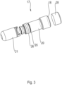
- the threaded bolt 17 is constructed in two parts and consists of a threaded guide part 20 screwed into the threaded bore 15 and a pressure piece 21 closer to the cylinder chamber 9, which is guided in the bore 30 in an axially displaceable manner.
- the pressure piece 21 is connected coaxially to the guide part 20 by means of a bayonet lock 22 and can rotate relative to the guide part 20 .
- the pressure piece 21 consists of a material of higher strength than the piston 10 and has a radially circumferential radius 23 at its end facing the cylinder chamber 9 .
- a chamfer could also be formed.
- the material of higher strength of the pressure piece 21 results in an intentional brinellation of the contact area of the piston 10 which, however, lies harmlessly radially outside the functional surfaces of the piston 10 .
- the pressure piece 21 is not deformed.
- the guide part 20 has a radially circumferential annular groove 25 on its lateral surface in its thread-free area, in which two sealing rings 26 made of an elastic material are arranged, which are prestressed both on the bottom of the annular groove 25 and on the unthreaded wall of the threaded bore 15 in plant.
- the end of the threaded bore 15 facing the radially outer lateral surface 16 of the brake housing 1 can be closed by a closure element 28 .
- the closure element 28 designed as a closure screw has a thread with which it is screwed into the threaded bore 15 .
- This slightly conical design of the closure element seals off the threaded bore 15 from leakage to the outside and from contamination to the inside.
- the locking piece also has the function of protecting the threaded bolt 17 from unauthorized access and avoiding accidental operation.
- the cylinder chamber 9 is permanently pressurized so that the piston 10 is held in its position further away from the disk set 4 against the force of the plate spring 11 and the disk brake is thus opened.
- the closure element 28 can be removed and the threaded bolt 17 can be screwed further into the threaded bore 15 using a hexagonal wrench.
- the outer face of the threaded bolt 17 has a hexagon socket 29 into which the hexagonal key can be inserted and the threaded bolt 17 can be rotated.
- An emergency can also consist in the fact that no pressure can be built up to act on the piston 10, for example because the engine of the vehicle is defective or cannot be used to build up the pressure for other reasons.
- the threaded bolt 17 is moved so far into the threaded bore 15 that the pressure piece 21 is moved into a position protruding into the cylinder chamber 9, a partial circumferential area 31 of the circumferential radius 23 on the piston 10 comes to rest and, if the threaded bolt 17 is rotated further moves it away from the disk pack 4 against the force of the plate spring 11 . This also releases the multi-disk brake and the vehicle can be moved to a workshop.
- the pressure piece 21 is supported with the area of its lateral surface 32 diametrically opposite the partial peripheral area 31 on the inner wall of the bore 30 .
- the sum of the frictional torques with which the pressure piece 21 rests against the piston 10 and the inner wall of the bore 30 is greater than the frictional torque between the guide part 20 and the pressure piece 21.
- the guide part 20 can thus be moved both in rotation and in translation, while the pressure piece 21 resting on the piston 10 can only be moved in translation.
Landscapes
- Engineering & Computer Science (AREA)
- General Engineering & Computer Science (AREA)
- Mechanical Engineering (AREA)
- Physics & Mathematics (AREA)
- Electromagnetism (AREA)
- Braking Arrangements (AREA)
Abstract
Description
- Die Erfindung bezieht sich auf eine Lamellenbremse für ein Kraftfahrzeug, mit einem in einer Lamellenkammer eines Bremsgehäuses auf einem Achskörper angeordneten Lamellenpaket mit zumindest einer Bremslamelle, mit einer Feder, durch die zum Schließen der Lamellenbremse das Lamellenpaket zusammendrückbar ist und mit einem an der Feder anliegenden und in einem Zylinderraum verschiebbar angeordneten Kolben, der zum Lösen der Lamellenbremse gegen die Kraft der Feder mit einem Druck beaufschlagbar ist und über den das Lamellenpaket direkt oder indirekt durch die Feder zusammendrückbar ist, mit einer mechanischen Notlösevorrichtung, durch die der Kolben zum Lösen der Lamellenbremse gegen die Kraft der Feder beaufschlagbar ist.
- Bei derartigen Lamellenbremsen mit einer Notlösevorrichtung ist es bekannt, daß die Notlöseeinrichtungen zu ihrer Betätigung axial oder radial zugänglich sind. Dies erfordert radial oder axial einen erheblichen Betätigungsraum um die Notlöseeinrichtung betätigen zu können, wodurch der gesamte erforderliche Bauraum der Lamellenbremse sehr groß sein muß.
- Aufgabe der Erfindung ist es daher eine Lamellenbremse für ein Kraftfahrzeug mit einer Notlösevorrichtung der eingangs genannten Art zu schaffen, die einen einfachen Aufbau und einen geringen Bauraumbedarf sowie eine gute Zugänglichkeit zur Lösevorrichtung aufweist.
- Diese Aufgabe wird erfindungsgemäß dadurch gelöst, daß im Bremsgehäuse eine Ausnehmung ausgebildet ist, die sich unter einem Winkel <90° zum Achskörper geneigt von der radial äußeren Mantelfläche des Bremsgehäuses zum Zylinderraum erstreckt und an dessen dem Lamellenpaket näheren Stirnwand in den Zylinderraum mündet, wobei in der Ausnehmung ein Stellbolzen angeordnet ist, der mit seinem zylinderraumseitigen Ende zwischen einer in den Zylinderraum ragenden und einer nicht in den Zylinderraum ragenden Position in der Ausnehmung verstellbar ist.
- Die Lamellenbremse ist vorzugsweise eine Parkbremse, die in allen Fahrzeugtypen angewendet werden kann.
- Der Winkel, unter dem die Ausnehmung zum Achskörper geneigt sich erstreckt, beträgt vorzugsweise zwischen 15° und 60°, insbesondere 30°.
- Zu eine Notlösung der Lamellenbremse wird der Stellbolzen in den Zylinderraum hineinbewegt und kommt dort zur Anlage an dem Kolben, wobei bei weiterer Hineinbewegung des Stellbolzens der Kolben in Löserichtung der Lamellenbremse gegen die Kraft der Feder verschoben wird und so die Lamellenbremse gelöst wird.
- Dabei kann die Lamellenbremse eine Parkbremse sein, die insbesondere eine sog. nasse Lamellenbremse ist.
- Die Ausnehmung ist dabei vorzugsweise zu einem stirnseitigen Ende des Bremsgehäuses hin geneigt, da dort ausreichender Raum zum Betätigen der Notlöseeinrichtung vorhanden ist.
- Der Stellbolzen kann vollständig in der Ausnehmung angeordnet sein und damit nicht über die radial äußere Mantelfläche hervorragen.
- Dies führt dazu, daß eine große Eigensicherheit gegen ungewollte Aktivierung der Notlösevorrichtung vorhanden ist.
- Durch die Anordnung der Notlösevorrichtung innerhalb des sowieso vorhandenen Bremsgehäuses ist keine Vergrößerung der Lamellenbremse und damit eine Vergrößerung des erforderlichen Bauraums nötig.
- In einfacher Ausbildung kann die Ausnehmung eine Gewindebohrung und der Stellbolzen ein Gewindebolzen sein, so daß keine aufwendige Mechanik zum Bewegen des Stellbolzens erforderlich ist.
- Weist das der radial äußeren Mantelfläche des Bremsgehäuses zugewandte Ende des Stellbolzens eine Werkzeugangriffskontur zur Aufnahme eines Drehwerkzeugs zum Verdrehen des Gewindebolzens auf, so werden permanent vorhandene und Bauraum benötigende Betätigungsorgane vermieden.
- Zum Schutz gegen Verschmutzung und gegen ungewollte Aktivierung der Notlösevorrichtung kann das der radial äußeren Mantelfläche des Bremsgehäuses zugewandte Ende der Ausnehmung von einem Verschlußelement verschließbar sein.
- Ebenfalls zum Schutz gegen Verschmutzung sowie zur Druckabdichtung des Zylinderraums kann der Stellbolzen abgedichtet in der Ausnehmung verstellbar sein.
- Der Stellbolzen kann zweiteilig ausgebildet sein und aus einem in der Ausnehmung axial geführten Führungsteil und einem Druckstück bestehen, wobei das Druckstück an dem dem Zylinderraum zugewandten Endbereich des Führungsteils angeordnet ist.
- Ist das Druckstück um die Längsachse der Ausnehmung relativ verdrehbar mit dem Führungsteil verbunden, so verdreht sich bei Anlage des Druckstücks am Kolben das Druckstück nicht mehr, während der Stellbolzen mit dem Führungsteil verdreht werden kann.
- In einfach zu montierender Ausbildung kann dazui das Druckstück mittels eines Bajonettverschlusses mit dem Führungsteil verbunden sein.
- Ist das Druckstück bei betätigter Notlösevorrichtung mit einem Teilumfangsbereich seines Übergangs zwischen seiner dem Kolben zugewandten Stirnseite und seiner zylindrischen Mantelfläche an dem Kolben und mit seiner dem Teilumfangsbereich diametral gegenüberliegenden Bereich seiner zylindrischen Mantelfläche an der Innenwand der Ausnehmung in Anlage, so wird das Druckstück gegen ein Verdrehen gesichert gehalten, wodurch ein Verschleiß an Kolben und Druckstück weitgehend vermieden wird.
- Ist dabei das Druckstück aus einem verschleißarmen und/oder zum Werkstoff des Kolbens reibungsarmen Werkstoff ausgebildet, so kommt es ebenfalls zu keinem wesentlichen Verschleiß an Druckstück und/oder Kolben.
- Ist die Feder eine Tellerfeder, so wird eine besonders axial kurze Baugröße der Lamellenbremse erreicht.
- Zur sicheren Normallösung der Lamellenbremse ist der Kolben vorzugsweise von einem Hydraulikdruck beaufschlagbar.
- Von dem von der Feder belasteten Kolben kann über einen in einem Betriebszylinder verschiebbar angeordneten Betriebsbremskolben das Lamellenpaket zusammendrückbar beaufschlagbar sein.
- Insbesondere, wenn die Lamellenbremse eine nasse Lamellenbremse ist, kann dabei der Zylinderraum des Kolbens und der Betriebszylinder des Betriebsbremskolbens durch eine Trennwand voneinander getrennt sein, die ein oder mehrere axial durchgehende Axialöffnungen aufweist, durch die Druckstücke des Kolbens gleicher Querschnittskontur abgedichtet hindurchgeführt sind, durch die der Betriebsbremskolben von dem Kolben in Schließrichtung des Lamellenpakets beaufschlagbar ist.
- Ein Ausführungsbeispiel der Erfindung ist in der Zeichnung dargestellt und wird im Folgenden näher beschrieben. Es zeigen:
- Figur 1
- einen Längsschnitt eines Ausschnitts einer Lamellenbremse bei nichtbetätigter Notlösevorrichtung
- Figur 2
- einen Längsschnitt eines Ausschnitts der Lamellenbremse nach
Figur 1 bei betätigter Notlösevorrichtung - Figur 3
- eine perspektivische Darstellung eines Stellbolzens der Lamellenbremse nach
Figur 1 . - Die dargestellte Lamellenbremse eines Fahrzeugs weist ein mehrteiliges Bremsgehäuse 1 auf, in dem eine abgedichtete und ein Öl enthaltende Lamellenkammer 2 angeordnet ist. In die Lamellenkammer 2 ragt koaxial ein nicht dargestellter drehbar gelagerter Achskörper, auf dem ein Lamellenpaket 4 mit mehreren Bremslamellen 5, 5' nebeneinander angeordnet ist. Jeweils axial zwischen zwei mit dem Achskörper drehfest verbundenen Bremslamellen 5 ist eine Bremslamelle 5' angeordnet, die drehfest mit dem Bremsgehäuse 1 verbunden ist.
- In dem Bremsgehäuse 1 ist ein Betriebszylinder 6 axial zur Lamellenkammer 2 ausgebildet, in dem ein Betriebsbremskolben 7 abgedichtet axial verschiebbar angeordnet ist.
- Von einer Trennwand 8 des Bremsgehäuses 1 getrennt ist koaxial zum Betriebszylinder 6 in einem Zylinderraum 9 des Bremsgehäuses 1 ein Kolben 10 abgedichtet axial verschiebbar geführt angeordnet, der über eine nicht dargestellte Druckleitung auf seiner dem Lamellenpaket 4 zugewandten Stirnseite von einem hydraulischen Druck beaufschlagbar ist.
- Die Trennwand 8 weist mehrere axial durchgehende Axialöffnungen auf, durch die Druckstücke 13 des Kolbens 10 abgedichtet hindurchgeführt sind und axial an dem Betriebsbremskolben 7 anliegen.
- An der dem Lamellenpaket 4 abgewandten Stirnseite der Kolbens 10 liegt eine an einem Anschlag 12 des Bremsgehäuses 1 abgestützte vorgespannte Tellerfeder 11 an, von der der Kolben 10 bei Nichtdruckbeaufschlagung des Zylinderraums 9 zum Lamellenpaket 4 hin bewegt wird und über die Druckstücke 13 den Betriebsbremszylinderkolben gegen das Lamellenpaket preßt. Dadurch werden die Bremslamellen 5 und 5' aneinandergepreßt und damit eine Drehbewegung des Achskörpers unterbunden.
- Erfolgt dann eine Druckbeaufschlagung des Zylinderraums 9, so bewegt sich der Kolben 10 entgegen der Kraft der Tellerfeder 11 vom Lamellenpaket 4 weg, so daß die Bremslamellen 5 nicht mehr mit den Bremslamellen 5' zusammengepreßt sind und damit der Achskörper frei drehen kann.
- Käme es zu einem Defekt dieses Lösevorgangs, so würde sich der Kolben 10 nicht entgegen der Kraft der Tellerfeder 11 vom Lamellenpaket 4 wegbewegen und die Lamellenbremse bliebe in ihrem geschlossenen Zustand.
- Um in einer solchen Situation trotzdem die Lamellenbremse lösen zu können, ist eine Notlösevorrichtung 14 vorhanden.
- Dazu ist im Bremsgehäuse 1 eine Ausnehmung als Bohrung 30 ausgebildet, die sich unter einem Winkel von 30° zum Achskörper von der radial äußeren umlaufenden Mantelfläche 16 des Bremsgehäuses zum Zylinderraum 9 erstreckt und in dessen dem Lamellenpaket 4 näheren Stirnwand 19 in den Zylinderraum 9 mündet. Die Bohrung 30 ist nur in ihrem dem Zylinderraum 9 entfernteren Bereich als Gewindebohrung 15 mit Gewinde 27 versehen und weist in ihrem davon zum Zylinderraum 9 sich erstreckenden Bereich einen dem Kernlochdurchmesser des Gewindes 27 entsprechenden Durchmesser auf.
- In die Gewindebohrung 15 ist ein Gewindebolzen 17 so weit eingeschraubt, daß zwischen stirnseitigen äußeren Ende 18 des Gewindebolzens 17 und dem äußeren Ende der Gewindebohrung 15 ein ein bestimmtes Einstellmaß bildender Abstand vorhanden ist. Dabei weist der Gewindebolzen 17 auch nur ein Gewinde in seinem nach außen gerichteten Endbereich auf, mit dem er in das Gewinde 27 der Gewindebohrung 15 eingeschraubt ist. Der dem Zylinderraum 9 zugewandte gewindefreie Bereich des Gewindebolzens 17 weist einen dem Kernlochdurchmesser des Gewindes 27 entsprechenden Durchmesser auf, so daß der Gewindebolzen 17 in diesem Bereich in der Gewindebohrung 15 axial geführt ist.
- In dieser in
Figur 1 dargestellten Lage befindet sich der Gewindebolzen 17 in seiner nicht in den Zylinderraum 9 ragenden Position. - Der Gewindebolzen 17 ist zweiteilig ausgebildet und besteht aus einem mit dem Gewinde versehenen und in die Gewindebohrung 15 eingeschraubten Führungsteil 20 sowie einem dem Zylinderraum 9 näheren Druckstück 21, das in der Bohrung 30 axial verschiebbar geführt ist. Mittels eines Bajonettverschlusses 22 ist das Druckstück 21 koaxial mit dem Führungsteil 20 verbunden und kann sich relativ zum Führungsteil 20 verdrehen.
- Das Druckstück 21 besteht aus einem Material höherer Festigkeit als der Kolben 10 und weist an seinem dem Zylinderraum 9 zugewandten Ende einen radial umlaufenden Radius 23 auf.
- Anstatt eines Radius 23 könnte auch eine Fase ausgebildet sein.
- Durch das Material höherer Festigkeit des Druckstücks 21 findet eine gewollte Brinellierung des Anlagebereichs des Kolbens 10 statt, die jedoch unschädlich radial außerhalb der Funktionsflächen des Kolbens 10 liegt. Eine Verformung des Druckstücks 21 erfolgt nicht.
- Damit der Gewindebolzen 17 sich durch z.B. Erschütterungen während des Fahrbetriebs nicht selbsttätig verdrehen kann, weist das Führungsteil 20 in seinem gewindefreien Bereich eine radial umlaufende Ringnut 25 an seiner Mantelfläche auf, in der zwei Dichtringe 26 aus einem elastischen Material angeordnet sind, die mit Vorspannung sowohl an dem Boden der Ringnut 25 als auch an der gewindefreien Wandung der Gewindebohrung 15 in Anlage ist.
- Das der radial äußeren Mantelfläche 16 des Bremsgehäuses 1 zugewandte Ende der Gewindebohrung 15 ist durch ein Verschlußelement 28 verschließbar. Dazu weist das als Verschlußschraube ausgebildete Verschlußelement 28 ein Gewinde auf, mit dem es in die Gewindebohrung 15 eingeschraubt ist. Durch diese leicht konische Ausbildung des Verschlußelements ist die Gewindebohrung 15 gegen Leckage nach außen und vor Verschmutzung nach innen abgeschottet.
- Das Verschlußstück hat weiterhin die Funktion den Gewindebolzen 17 vor unbefugtem Zugriff zu schützen bzw. eine versehendliche Bedienung zu vermeiden.
- Während des Fahrbetriebs des Fahrzeugs ist der Zylinderraum 9 permanent mit einem Druck beaufschlagt, so daß der Kolben 10 gegen die Kraft der Tellerfeder 11 in seine dem Lamellenpaket 4 entferntere Lage gehalten und somit die Lamellenbremse geöffnet ist.
- Ist dies in einem Notfall nicht der Fall und der Zylinderraum 9 trotz beabsichtigtem Fahrbetrieb drucklos, so kann das Verschlußelement 28 entfernt und mittels eines Sechskantschlüssels der Gewindebolzen 17 weiter in die Gewindebohrung 15 eingeschraubt werden. Dazu weist die äußere Stirnseite des Gewindebolzens 17 einen Innensechskant 29 auf, in den der Sechskantschlüssel eingeführt und der Gewindebolzen 17 verdreht werden kann.
- Ein Notfall kann auch darin bestehen, daß kein Druck zur Beaufschlagung des Kolbens 10 aufgebaut werden kann, weil z.B. der Motor des Fahrzeugs defekt ist oder aus anderen Gründen nicht zum Druckaufbau benutzt werden kann.
- Dabei wird der Gewindebolzen 17 so weit in die Gewindebohrung 15 hineinbewegt, daß das Druckstück 21 in eine in den Zylinderraum 9 ragende Position hineinbewegt wird, an dem Kolben 10 mit einem Teilumfangsbereich 31 des umlaufenden Radius 23 zur Anlage kommt und bei weiterem Verdrehen des Gewindebolzens 17 diesen gegen die Kraft der Tellerfeder 11 von dem Lamellenpaket 4 wegbewegt. Dabei löst sich auch die Lamellenbremse und das Fahrzeug kann in eine Werkstatt bewegt werden.
- Als Reaktion zur Anlage des Teilumfangsbereichs 31 des Radius 23 an dem Kolben 10 stützt sich das Druckstück 21 mit dem dem Teilumfangsbereich 31 diametral gegenüberliegenden Bereich seiner Mantelfläche 32 an der Innenwand der Bohrung 30 ab. Dabei ist die Summe der Reibmomente, mit denen das Druckstück 21 an dem Kolben 10 und an der Innenwand der Bohrung 30 anliegt, größer als das Reibmoment zwischen dem Führungsteil 20 und dem Druckstück 21.
- Damit ist das Führungsteil 20 sowohl rotatorisch als auch translatorisch bewegbar, während das an dem Kolben 10 anliegende Druckstück 21 nur translatorisch bewegbar ist.
-
- 1
- Bremsgehäuse
- 2
- Lamellenkammer
- 4
- Lamellenpaket
- 5
- Bremslamelle
- 5'
- Bremslamelle
- 6
- Betriebszylinder
- 7
- Betriebsbremskolben
- 8
- Trennwand
- 9
- Zylinderraum
- 10
- Kolben
- 11
- Tellerfeder
- 12
- Anschlag
- 13
- Druckstück
- 14
- Notlösevorrichtung
- 15
- Gewindebohrung
- 16
- Mantelfläche
- 17
- Gewindebolzen
- 18
- äußeres Ende
- 19
- Stirnwand
- 20
- Führungsteil
- 21
- Druckstück
- 22
- Bajonettverschluß
- 23
- Radius
- 24
- Kolbenstirnwand
- 25
- Ringnut
- 26
- Dichtringe
- 27
- Gewinde
- 28
- Verschluß
- 29
- Innensechskant
- 30
- Bohrung
- 31
- Teilumfangsbereich
- 32
- Mantelfläche
Claims (14)
- Lamellenbremse für ein Kraftfahrzeug, mit einem in einer Lamellenkammer (2) eines Bremsgehäuses (1) auf einem Achskörper angeordneten Lamellenpaket (4) mit zumindest einer Bremslamelle (5, 5'), mit einer Feder, durch die zum Schließen der Lamellenbremse das Lamellenpaket (4) zusammendrückbar ist und mit einem an der Feder anliegenden und in einem Zylinderraum (9) verschiebbar angeordneten Kolben (10), der zum Lösen der Lamellenbremse gegen die Kraft der Feder mit einem Druck beaufschlagbar ist und über den das Lamellenpaket (4) direkt oder indirekt durch die Feder zusammendrückbar ist, mit einer mechanischen Notlösevorrichtung (14), durch die der Kolben (10) zum Lösen der Lamellenbremse gegen die Kraft der Feder beaufschlagbar ist, dadurch gekennzeichnet, daß im Bremsgehäuse (1) eine Ausnehmung (30) ausgebildet ist, die sich unter einem Winkel <90° zum Achskörper geneigt von der radial äußeren Mantelfläche (16) des Bremsgehäuses (1) zum Zylinderraum (9) erstreckt und an dessen dem Lamellenpaket (4) näheren Stirnwand (19) in den Zylinderraum (9) mündet, wobei in der Ausnehmung (30) ein Stellbolzen angeordnet ist, der mit seinem zylinderraumseitigen Ende zwischen einer in den Zylinderraum (9) ragenden und einer nicht in den Zylinderraum (9) ragenden Position in der Ausnehmung (30) verstellbar ist.
- Lamellenbremse nach Anspruch 1, dadurch gekennzeichnet, dass die Ausnehmung eine Gewindebohrung (15) und der Stellbolzen ein Gewindebolzen (17) ist.
- Lamellenbremse nach Anspruch 2, dadurch gekennzeichnet, dass das der radial äußeren Mantelfläche (16) des Bremsgehäuses (1) zugewandte Ende des Stellbolzens eine Werkzeugangriffskontur zur Aufnahme eines Drehwerkzeugs zum Verdrehen des Gewindebolzens (17) aufweist.
- Lamellenbremse nach einem der vorhergehenden Ansprüche, dadurch gekennzeichnet, dass das der radial äußeren Mantelfläche (16) des Bremsgehäuses (1) zugewandte Ende der Ausnehmung (30) von einem Verschlußelement (28) verschließbar ist.
- Lamellenbremse nach einem der vorhergehenden Ansprüche, dadurch gekennzeichnet, dass der Stellbolzen abgedichtet in der Ausnehmung (30) verstellbar ist.
- Lamellenbremse nach einem der vorhergehenden Ansprüche, dadurch gekennzeichnet, dass der Stellbolzen zweiteilig ausgebildet ist und aus einem in der Ausnehmung (30) axial geführten Führungsteil (20) und einem Druckstück (21) besteht, wobei das Druckstück (21) an dem dem Zylinderraum (9) zugewandten Endbereich des Führungsteils (20) angeordnet ist.
- Lamellenbremse nach Anspruch 6, dadurch gekennzeichnet, dass das Druckstück um die Längsachse der Ausnehmung (30) relativ verdrehbar mit dem Führungsteil (20) verbunden ist.
- Lamellenbremse nach einem der Ansprüche 6 und 7, dadurch gekennzeichnet, dass das Druckstück (21) mittels eines Bajonettverschlusses (22) mit dem Führungsteil (20) verbindbar ist.
- Lamellenbremse nach einem der Ansprüche 7 und 8, dadurch gekennzeichnet, dass das Druckstück (21) bei betätigter Notlösevorrichtung mit einem Teilumfangsbereich (31) seines Übergangs zwischen seiner dem Kolben (10) zugewandten Stirnseite und seiner zylindrischen Mantelfläche (32) an dem Kolben (10) und mit seiner dem Teilumfangsbereich (31) diametral gegenüberliegenden Bereich seiner zylindrischen Mantelfläche (32) an der Innenwand der Ausnehmung (30) in Anlage ist.
- Lamellenbremse nach Anspruch 6, dadurch gekennzeichnet, dass das Druckstück (21) aus einem verschleißarmen und/oder zum Werkstoff des Kolbens (10) reibungsarmen Werkstoff ausgebildet ist.
- Lamellenbremse nach einem der vorhergehenden Ansprüche, dadurch gekennzeichnet, dass die Feder eine Tellerfeder (11) ist.
- Lamellenbremse nach einem der vorhergehenden Ansprüche, dadurch gekennzeichnet, dass der Kolben (10) von einem Hydraulikdruck beaufschlagbar ist.
- Lamellenbremse nach einem der vorhergehenden Ansprüche, dadurch gekennzeichnet, dass von dem von der Feder belasteten Kolben (10) über einen in einem Betriebszylinder (6) verschiebbar angeordneten Betriebsbremskolben (7) das Lamellenpaket (4) zusammendrückbar beaufschlagbar ist.
- Lamellenbremse nach Anspruch 13, dadurch gekennzeichnet, dass der Zylinderraum (9) des Kolbens (10) und der Betriebszylinder (6) des Betriebsbremskolbens (7) durch eine Trennwand (8) voneinander getrennt sind, die ein oder mehrere axial durchgehende Axialöffnungen aufweist, durch die Druckstücke (13) des Kolbens (10) gleicher Querschnittskontur abgedichtet hindurchgeführt sind, durch die der Betriebsbremskolben (7) von dem Kolben (10) in Schließrichtung des Lamellenpakets (4) beaufschlagbar ist.
Applications Claiming Priority (1)
| Application Number | Priority Date | Filing Date | Title |
|---|---|---|---|
| DE102021213894.2A DE102021213894B3 (de) | 2021-12-07 | 2021-12-07 | Lamellenbremse für ein Kraftfahrzeug |
Publications (3)
| Publication Number | Publication Date |
|---|---|
| EP4194713A1 true EP4194713A1 (de) | 2023-06-14 |
| EP4194713B1 EP4194713B1 (de) | 2024-08-28 |
| EP4194713C0 EP4194713C0 (de) | 2024-08-28 |
Family
ID=84439910
Family Applications (1)
| Application Number | Title | Priority Date | Filing Date |
|---|---|---|---|
| EP22211931.5A Active EP4194713B1 (de) | 2021-12-07 | 2022-12-07 | Lamellenbremse für ein kraftfahrzeug |
Country Status (2)
| Country | Link |
|---|---|
| EP (1) | EP4194713B1 (de) |
| DE (1) | DE102021213894B3 (de) |
Families Citing this family (1)
| Publication number | Priority date | Publication date | Assignee | Title |
|---|---|---|---|---|
| DE102023202915B4 (de) * | 2023-03-30 | 2025-05-22 | Zf Friedrichshafen Ag | Gewindebolzenanordnung und Notentriegelung einer Parkbremse |
Citations (3)
| Publication number | Priority date | Publication date | Assignee | Title |
|---|---|---|---|---|
| US4540073A (en) * | 1981-11-23 | 1985-09-10 | SO.M.A. Europe Transmission-Societe Nouvelle Mecanique et Automobile | Wheel hub with reduction gear and multiple disc brake |
| US6321882B1 (en) * | 1999-08-25 | 2001-11-27 | Eaton Corporation | External manual brake release |
| US6585088B1 (en) * | 2000-05-10 | 2003-07-01 | Poclain Hydraulics Industrie | Braking system for braking a rotor relative to a stator |
Family Cites Families (2)
| Publication number | Priority date | Publication date | Assignee | Title |
|---|---|---|---|---|
| DE19858124C2 (de) | 1998-12-16 | 2003-06-18 | Naf Neunkirchener Achsenfabrik | Radantrieb |
| DE20014539U1 (de) | 2000-08-23 | 2000-12-07 | Knott GmbH, 83125 Eggstätt | Bremse mit kombinierter Notlöse- und Einstell-/Nachstellvorrichtung |
-
2021
- 2021-12-07 DE DE102021213894.2A patent/DE102021213894B3/de active Active
-
2022
- 2022-12-07 EP EP22211931.5A patent/EP4194713B1/de active Active
Patent Citations (3)
| Publication number | Priority date | Publication date | Assignee | Title |
|---|---|---|---|---|
| US4540073A (en) * | 1981-11-23 | 1985-09-10 | SO.M.A. Europe Transmission-Societe Nouvelle Mecanique et Automobile | Wheel hub with reduction gear and multiple disc brake |
| US6321882B1 (en) * | 1999-08-25 | 2001-11-27 | Eaton Corporation | External manual brake release |
| US6585088B1 (en) * | 2000-05-10 | 2003-07-01 | Poclain Hydraulics Industrie | Braking system for braking a rotor relative to a stator |
Also Published As
| Publication number | Publication date |
|---|---|
| DE102021213894B3 (de) | 2023-04-20 |
| EP4194713B1 (de) | 2024-08-28 |
| EP4194713C0 (de) | 2024-08-28 |
Similar Documents
| Publication | Publication Date | Title |
|---|---|---|
| DE19543612C1 (de) | Spannvorrichtung mit integrierter Fluid-Drehdurchführung | |
| EP0224516B1 (de) | Absperrorgan für rohrleitungen | |
| EP4003649B1 (de) | Bohrungsspanner | |
| EP0397915A2 (de) | Pneumatisches Stellglied | |
| DE102016012865A1 (de) | Selbstjustierender pneumatischer Kupplungsaktor | |
| DE69113265T2 (de) | Schliessventilanordnung. | |
| DE68907710T2 (de) | Ventil mit nichtsteigender Spindel und Verfahren zum Ersetzen einer permanenten Dichtung. | |
| DE102007015209B3 (de) | Kompakt-Kombibremszylinder mit pneumatisch betätigbarem Sperrmechanismus | |
| DE69331337T2 (de) | Federspeicherbremszylinder und bolzenverriegelung dafür | |
| DE102021213894B3 (de) | Lamellenbremse für ein Kraftfahrzeug | |
| EP2132073B1 (de) | Kompakt-kombizylinder mit manueller lösevorrichtung | |
| EP0457030B1 (de) | Federspeicherzylinder für druckluftbetätigte Fahrzeugbremsen | |
| DE20014539U1 (de) | Bremse mit kombinierter Notlöse- und Einstell-/Nachstellvorrichtung | |
| DE4112641A1 (de) | Bremszylinder fuer hydraulisch und mechanisch betaetigbare scheibenbremsen | |
| DE102006001893B4 (de) | Parkbremse für ein Kraftfahrzeug | |
| EP1170512B1 (de) | Druckmittelbetriebener Arbeitszylinder mit mechanischer Wegsperrung im drucklosen Zustand | |
| EP1339592B1 (de) | Federspeicherbremszylinder mit einer notlöseeinrichtung | |
| DE10249509A1 (de) | Pneumatischer Stellantrieb | |
| DE102019209150A1 (de) | Druckfluid-Betätigungsanordnung für eine Reibungskupplung | |
| DE19902297C1 (de) | Drehantrieb mit außerhalb der Druckräume liegenden Reibflächen zur Übertragung des Drehmomentes | |
| EP4411162B1 (de) | Bremse mit einer einrichtung zur ermittlung einer verschleissgrenze | |
| DE2310304C3 (de) | Kombinierter Druckmittel- und Federspeicherbremszylinder für eine Fahrzeugradbremse | |
| DE102023202915B4 (de) | Gewindebolzenanordnung und Notentriegelung einer Parkbremse | |
| DE10356597B3 (de) | Verriegelungszylinder | |
| DE2363268B2 (de) | Kombinierter Druckmittel-Federspeicherbremszylinder für eine Fahrzeugradbremse |
Legal Events
| Date | Code | Title | Description |
|---|---|---|---|
| PUAI | Public reference made under article 153(3) epc to a published international application that has entered the european phase |
Free format text: ORIGINAL CODE: 0009012 |
|
| STAA | Information on the status of an ep patent application or granted ep patent |
Free format text: STATUS: THE APPLICATION HAS BEEN PUBLISHED |
|
| AK | Designated contracting states |
Kind code of ref document: A1 Designated state(s): AL AT BE BG CH CY CZ DE DK EE ES FI FR GB GR HR HU IE IS IT LI LT LU LV MC ME MK MT NL NO PL PT RO RS SE SI SK SM TR |
|
| STAA | Information on the status of an ep patent application or granted ep patent |
Free format text: STATUS: REQUEST FOR EXAMINATION WAS MADE |
|
| 17P | Request for examination filed |
Effective date: 20231214 |
|
| RBV | Designated contracting states (corrected) |
Designated state(s): AL AT BE BG CH CY CZ DE DK EE ES FI FR GB GR HR HU IE IS IT LI LT LU LV MC ME MK MT NL NO PL PT RO RS SE SI SK SM TR |
|
| GRAP | Despatch of communication of intention to grant a patent |
Free format text: ORIGINAL CODE: EPIDOSNIGR1 |
|
| STAA | Information on the status of an ep patent application or granted ep patent |
Free format text: STATUS: GRANT OF PATENT IS INTENDED |
|
| RIC1 | Information provided on ipc code assigned before grant |
Ipc: F16D 121/16 20120101ALN20240412BHEP Ipc: F16D 127/04 20120101ALN20240412BHEP Ipc: F16D 59/02 20060101ALI20240412BHEP Ipc: F16D 55/40 20060101AFI20240412BHEP |
|
| INTG | Intention to grant announced |
Effective date: 20240429 |
|
| GRAS | Grant fee paid |
Free format text: ORIGINAL CODE: EPIDOSNIGR3 |
|
| GRAA | (expected) grant |
Free format text: ORIGINAL CODE: 0009210 |
|
| STAA | Information on the status of an ep patent application or granted ep patent |
Free format text: STATUS: THE PATENT HAS BEEN GRANTED |
|
| AK | Designated contracting states |
Kind code of ref document: B1 Designated state(s): AL AT BE BG CH CY CZ DE DK EE ES FI FR GB GR HR HU IE IS IT LI LT LU LV MC ME MK MT NL NO PL PT RO RS SE SI SK SM TR |
|
| REG | Reference to a national code |
Ref country code: CH Ref legal event code: EP |
|
| REG | Reference to a national code |
Ref country code: DE Ref legal event code: R096 Ref document number: 502022001574 Country of ref document: DE |
|
| REG | Reference to a national code |
Ref country code: IE Ref legal event code: FG4D Free format text: LANGUAGE OF EP DOCUMENT: GERMAN |
|
| U01 | Request for unitary effect filed |
Effective date: 20240828 |
|
| U07 | Unitary effect registered |
Designated state(s): AT BE BG DE DK EE FI FR IT LT LU LV MT NL PT RO SE SI Effective date: 20240905 |
|
| U20 | Renewal fee for the european patent with unitary effect paid |
Year of fee payment: 3 Effective date: 20241107 |
|
| PG25 | Lapsed in a contracting state [announced via postgrant information from national office to epo] |
Ref country code: NO Free format text: LAPSE BECAUSE OF FAILURE TO SUBMIT A TRANSLATION OF THE DESCRIPTION OR TO PAY THE FEE WITHIN THE PRESCRIBED TIME-LIMIT Effective date: 20241128 |
|
| PG25 | Lapsed in a contracting state [announced via postgrant information from national office to epo] |
Ref country code: PL Free format text: LAPSE BECAUSE OF FAILURE TO SUBMIT A TRANSLATION OF THE DESCRIPTION OR TO PAY THE FEE WITHIN THE PRESCRIBED TIME-LIMIT Effective date: 20240828 Ref country code: GR Free format text: LAPSE BECAUSE OF FAILURE TO SUBMIT A TRANSLATION OF THE DESCRIPTION OR TO PAY THE FEE WITHIN THE PRESCRIBED TIME-LIMIT Effective date: 20241129 |
|
| PG25 | Lapsed in a contracting state [announced via postgrant information from national office to epo] |
Ref country code: IS Free format text: LAPSE BECAUSE OF FAILURE TO SUBMIT A TRANSLATION OF THE DESCRIPTION OR TO PAY THE FEE WITHIN THE PRESCRIBED TIME-LIMIT Effective date: 20241228 |
|
| PG25 | Lapsed in a contracting state [announced via postgrant information from national office to epo] |
Ref country code: HR Free format text: LAPSE BECAUSE OF FAILURE TO SUBMIT A TRANSLATION OF THE DESCRIPTION OR TO PAY THE FEE WITHIN THE PRESCRIBED TIME-LIMIT Effective date: 20240828 |
|
| PG25 | Lapsed in a contracting state [announced via postgrant information from national office to epo] |
Ref country code: RS Free format text: LAPSE BECAUSE OF FAILURE TO SUBMIT A TRANSLATION OF THE DESCRIPTION OR TO PAY THE FEE WITHIN THE PRESCRIBED TIME-LIMIT Effective date: 20241128 Ref country code: ES Free format text: LAPSE BECAUSE OF FAILURE TO SUBMIT A TRANSLATION OF THE DESCRIPTION OR TO PAY THE FEE WITHIN THE PRESCRIBED TIME-LIMIT Effective date: 20240828 |
|
| PG25 | Lapsed in a contracting state [announced via postgrant information from national office to epo] |
Ref country code: RS Free format text: LAPSE BECAUSE OF FAILURE TO SUBMIT A TRANSLATION OF THE DESCRIPTION OR TO PAY THE FEE WITHIN THE PRESCRIBED TIME-LIMIT Effective date: 20241128 Ref country code: PL Free format text: LAPSE BECAUSE OF FAILURE TO SUBMIT A TRANSLATION OF THE DESCRIPTION OR TO PAY THE FEE WITHIN THE PRESCRIBED TIME-LIMIT Effective date: 20240828 Ref country code: NO Free format text: LAPSE BECAUSE OF FAILURE TO SUBMIT A TRANSLATION OF THE DESCRIPTION OR TO PAY THE FEE WITHIN THE PRESCRIBED TIME-LIMIT Effective date: 20241128 Ref country code: IS Free format text: LAPSE BECAUSE OF FAILURE TO SUBMIT A TRANSLATION OF THE DESCRIPTION OR TO PAY THE FEE WITHIN THE PRESCRIBED TIME-LIMIT Effective date: 20241228 Ref country code: HR Free format text: LAPSE BECAUSE OF FAILURE TO SUBMIT A TRANSLATION OF THE DESCRIPTION OR TO PAY THE FEE WITHIN THE PRESCRIBED TIME-LIMIT Effective date: 20240828 Ref country code: GR Free format text: LAPSE BECAUSE OF FAILURE TO SUBMIT A TRANSLATION OF THE DESCRIPTION OR TO PAY THE FEE WITHIN THE PRESCRIBED TIME-LIMIT Effective date: 20241129 Ref country code: ES Free format text: LAPSE BECAUSE OF FAILURE TO SUBMIT A TRANSLATION OF THE DESCRIPTION OR TO PAY THE FEE WITHIN THE PRESCRIBED TIME-LIMIT Effective date: 20240828 |
|
| PG25 | Lapsed in a contracting state [announced via postgrant information from national office to epo] |
Ref country code: SM Free format text: LAPSE BECAUSE OF FAILURE TO SUBMIT A TRANSLATION OF THE DESCRIPTION OR TO PAY THE FEE WITHIN THE PRESCRIBED TIME-LIMIT Effective date: 20240828 |
|
| PG25 | Lapsed in a contracting state [announced via postgrant information from national office to epo] |
Ref country code: CZ Free format text: LAPSE BECAUSE OF FAILURE TO SUBMIT A TRANSLATION OF THE DESCRIPTION OR TO PAY THE FEE WITHIN THE PRESCRIBED TIME-LIMIT Effective date: 20240828 |
|
| PG25 | Lapsed in a contracting state [announced via postgrant information from national office to epo] |
Ref country code: SK Free format text: LAPSE BECAUSE OF FAILURE TO SUBMIT A TRANSLATION OF THE DESCRIPTION OR TO PAY THE FEE WITHIN THE PRESCRIBED TIME-LIMIT Effective date: 20240828 |
|
| PLBE | No opposition filed within time limit |
Free format text: ORIGINAL CODE: 0009261 |
|
| STAA | Information on the status of an ep patent application or granted ep patent |
Free format text: STATUS: NO OPPOSITION FILED WITHIN TIME LIMIT |
|
| PG25 | Lapsed in a contracting state [announced via postgrant information from national office to epo] |
Ref country code: MC Free format text: LAPSE BECAUSE OF FAILURE TO SUBMIT A TRANSLATION OF THE DESCRIPTION OR TO PAY THE FEE WITHIN THE PRESCRIBED TIME-LIMIT Effective date: 20240828 |
|
| 26N | No opposition filed |
Effective date: 20250530 |
|
| PG25 | Lapsed in a contracting state [announced via postgrant information from national office to epo] |
Ref country code: IE Free format text: LAPSE BECAUSE OF NON-PAYMENT OF DUE FEES Effective date: 20241207 |
|
| U20 | Renewal fee for the european patent with unitary effect paid |
Year of fee payment: 4 Effective date: 20251110 |
|
| PG25 | Lapsed in a contracting state [announced via postgrant information from national office to epo] |
Ref country code: CY Free format text: LAPSE BECAUSE OF FAILURE TO SUBMIT A TRANSLATION OF THE DESCRIPTION OR TO PAY THE FEE WITHIN THE PRESCRIBED TIME-LIMIT; INVALID AB INITIO Effective date: 20221207 |