EP4194344B1 - Ttc-antennenanordnung für einen flachen satelliten - Google Patents
Ttc-antennenanordnung für einen flachen satelliten Download PDFInfo
- Publication number
- EP4194344B1 EP4194344B1 EP22211875.4A EP22211875A EP4194344B1 EP 4194344 B1 EP4194344 B1 EP 4194344B1 EP 22211875 A EP22211875 A EP 22211875A EP 4194344 B1 EP4194344 B1 EP 4194344B1
- Authority
- EP
- European Patent Office
- Prior art keywords
- antennas
- platform
- satellite
- remote control
- antenna
- Prior art date
- Legal status (The legal status is an assumption and is not a legal conclusion. Google has not performed a legal analysis and makes no representation as to the accuracy of the status listed.)
- Active
Links
- 238000005259 measurement Methods 0.000 claims description 11
- 230000010355 oscillation Effects 0.000 description 11
- 230000005855 radiation Effects 0.000 description 5
- 238000010586 diagram Methods 0.000 description 4
- 230000010354 integration Effects 0.000 description 4
- 230000005540 biological transmission Effects 0.000 description 3
- 230000000694 effects Effects 0.000 description 3
- 230000003321 amplification Effects 0.000 description 2
- 238000004519 manufacturing process Methods 0.000 description 2
- 238000000034 method Methods 0.000 description 2
- 230000006855 networking Effects 0.000 description 2
- 238000003199 nucleic acid amplification method Methods 0.000 description 2
- 241000985719 Antennariidae Species 0.000 description 1
- 230000005355 Hall effect Effects 0.000 description 1
- 230000015556 catabolic process Effects 0.000 description 1
- 230000002860 competitive effect Effects 0.000 description 1
- 239000002131 composite material Substances 0.000 description 1
- 230000008878 coupling Effects 0.000 description 1
- 238000010168 coupling process Methods 0.000 description 1
- 238000005859 coupling reaction Methods 0.000 description 1
- 238000009429 electrical wiring Methods 0.000 description 1
- 230000017525 heat dissipation Effects 0.000 description 1
- 238000003384 imaging method Methods 0.000 description 1
- 229910052743 krypton Inorganic materials 0.000 description 1
- DNNSSWSSYDEUBZ-UHFFFAOYSA-N krypton atom Chemical compound [Kr] DNNSSWSSYDEUBZ-UHFFFAOYSA-N 0.000 description 1
- 238000013178 mathematical model Methods 0.000 description 1
- 230000010363 phase shift Effects 0.000 description 1
- 230000010287 polarization Effects 0.000 description 1
- 230000006798 recombination Effects 0.000 description 1
- 238000005215 recombination Methods 0.000 description 1
- 230000035939 shock Effects 0.000 description 1
- 229910052724 xenon Inorganic materials 0.000 description 1
- FHNFHKCVQCLJFQ-UHFFFAOYSA-N xenon atom Chemical compound [Xe] FHNFHKCVQCLJFQ-UHFFFAOYSA-N 0.000 description 1
Images


Classifications
-
- B—PERFORMING OPERATIONS; TRANSPORTING
- B64—AIRCRAFT; AVIATION; COSMONAUTICS
- B64G—COSMONAUTICS; VEHICLES OR EQUIPMENT THEREFOR
- B64G1/00—Cosmonautic vehicles
- B64G1/22—Parts of, or equipment specially adapted for fitting in or to, cosmonautic vehicles
- B64G1/66—Arrangements or adaptations of apparatus or instruments, not otherwise provided for
-
- B—PERFORMING OPERATIONS; TRANSPORTING
- B64—AIRCRAFT; AVIATION; COSMONAUTICS
- B64G—COSMONAUTICS; VEHICLES OR EQUIPMENT THEREFOR
- B64G1/00—Cosmonautic vehicles
- B64G1/10—Artificial satellites; Systems of such satellites; Interplanetary vehicles
-
- B—PERFORMING OPERATIONS; TRANSPORTING
- B64—AIRCRAFT; AVIATION; COSMONAUTICS
- B64G—COSMONAUTICS; VEHICLES OR EQUIPMENT THEREFOR
- B64G1/00—Cosmonautic vehicles
- B64G1/22—Parts of, or equipment specially adapted for fitting in or to, cosmonautic vehicles
- B64G1/42—Arrangements or adaptations of power supply systems
- B64G1/44—Arrangements or adaptations of power supply systems using radiation, e.g. deployable solar arrays
-
- H—ELECTRICITY
- H01—ELECTRIC ELEMENTS
- H01Q—ANTENNAS, i.e. RADIO AERIALS
- H01Q1/00—Details of, or arrangements associated with, antennas
- H01Q1/27—Adaptation for use in or on movable bodies
- H01Q1/28—Adaptation for use in or on aircraft, missiles, satellites, or balloons
- H01Q1/288—Satellite antennas
-
- H—ELECTRICITY
- H04—ELECTRIC COMMUNICATION TECHNIQUE
- H04B—TRANSMISSION
- H04B7/00—Radio transmission systems, i.e. using radiation field
- H04B7/14—Relay systems
- H04B7/15—Active relay systems
- H04B7/185—Space-based or airborne stations; Stations for satellite systems
- H04B7/1851—Systems using a satellite or space-based relay
- H04B7/18515—Transmission equipment in satellites or space-based relays
Definitions
- the invention relates to the field of satellites, and in particular a satellite comprising an antenna system.
- the satellite When positioning a satellite, and throughout its mission, the satellite must be able to communicate at any time with a ground control center, whatever the attitude of the platform.
- the satellite has a system called “TTC” (“Telemetry, Tracking and Command”, an expression meaning in French telemetry, tracking and remote control).
- TTC Telemetry, Tracking and Command
- a telemetry link makes it possible to transmit information relating to the state of the satellite to the control center, through a plurality of measurements.
- a remote control link makes it possible to transmit, from the control center, specific commands for processing any event taking place in the satellite (orbit maneuvers, equipment tests, anomalies, breakdowns, etc.).
- the TTC antenna system is generally composed of two Tx telemetry antennas, forming an omnidirectional telemetry antenna assembly, and two Rx remote control antennas, forming an omnidirectional remote control antenna assembly.
- FIG. 1 An example of a classic TTC system is shown on the figure 1 .
- a classic TTC system includes, for telemetry, a transponder TP1, in order to modulate the telemetry signals TM coming from the on-board computer OBC of the PL platform, a coupler CP1, which makes it possible to split the signal to be transmitted on each of the antennas, namely a first antenna called the Tx+Z earth antenna, and an antenna located on the other side of the satellite, called the Tx-Z anti-earth antenna.
- the coverage of each antenna is as hemispherical as possible.
- the TTC system includes a first antenna called the Rx+Z earth antenna, and an antenna located on the other side of the satellite, called the Rx-Z anti-earth antenna, a coupler CP2, to sum the signals received on the two antennas, and a TP2 transponder, to demodulate the TC remote control signals, and to transmit them to the platform's OBC on-board computer.
- the TC remote control and TM telemetry data can respectively be transmitted to the PL payload or be transmitted by the PL payload, via the on-board computer OBC.
- the antennas dedicated to remote control and the antennas dedicated to telemetry can radiate according to distinct polarizations, for example in a left circular and/or right circular manner, in order to minimize interference between the two links.
- the ground and anti-ground antennas are arranged to radiate in opposite directions.
- Each antenna thus operates in a cone of +/-75°, which is sufficient to ensure a connection with the control center, whatever the attitude of the platform, with one or the other of the earth antennas or anti-earth.
- Each of the antennas of an earth and anti-earth pair must thus be arranged diametrically opposite, and in places completely clear of the platform, in particular by placing the antennas at the end of masts fixed to the platform, or in two opposite corners of the platform, to prevent part of the satellite from obscuring the half-space in front of the antenna.
- the antennas of an earth/anti-earth pair are arranged several meters apart from each other, for the largest platforms, which generates oscillations.
- FIG. 2 illustrates the amplitude (in dB) of the signal received by the transponder of a conventional satellite, as a function of the attitude of the satellite, for the remote control link in the C band (between 3.4 and 4.2 GHz in reception ), when the distance between the earth antenna and the anti-earth antenna are approximately 100 ⁇ apart, where ⁇ corresponds to the wavelength of the received signal.
- the radiation pattern of each individual horn was modeled mathematically, based on measurements taken in an anechoic chamber.
- the different horn networking curves calculated from the mathematical model of the radiation pattern of an individual horn, correspond to the different cross-sectional planes of the antenna.
- significant oscillations of the composite signal greater than 5 dB, appear between +60° and +120° (so-called “ripple” phenomenon). These oscillations, due to phase recombinations, harm the link budget.
- the document FR 2 789 652 A1 discloses a satellite whose duration of the manufacturing cycle and stay in the integration room is reduced.
- the document FR 2 788 179 A1 discloses a method for transmitting signals to a satellite having at least two antennas in hot redundancy and whose diagrams overlap, for a TTC link.
- mega-constellations for example the mega-constellation “Starlink” (registered trademark) offered by the aerospace manufacturer “SpaceX” (registered trademark), leads satellite manufacturers to propose new satellite architectures.
- the invention aims to remedy the aforementioned drawbacks, by taking advantage of the characteristics of flat satellites.
- the platform includes a transponder, the transponder being adjacent to the antenna system.
- the two remote control antennas are arranged between the transponder and the two telemetry antennas.
- the transponder is placed between the two remote control antennas and the two telemetry antennas.
- the platform comprises an arm forming an extension of the platform in the plane of the platform, along an axis corresponding to the junction between the platform and the solar panel, the antenna system being arranged on said arm of the platform.
- the arm of the platform comprises a deployment device, said deployment device being equipped with a low-shock passive system.
- the satellite comprises a first coupler configured to add signals coming from the remote control antennas, a second coupler configured to distribute a telemetry signal to the telemetry antennas, the first coupler and the second coupler being respectively connected between the remote control antennas , and between the telemetry antennas.
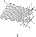
- the satellite according to the invention is illustrated on the Figure 3 . It includes a PF platform, with a planar structure, as opposed to cubic satellites, or equivalents, and whose length/width/height dimensions have the same order of magnitude.
- planar structure we therefore mean a satellite whose smallest dimension of the platform is less than or equal to ⁇ , where ⁇ corresponds to the wavelength of the remote control or telemetry signal.
- the planar structure makes it possible, in particular, during the satellite launch phase, to stack dozens of satellites (not deployed) in the launcher fairing.
- the platform can be rectangular, or even take the shape of a disc, in order to be adapted to the cylindrical shape typical of launcher caps. It can also be in the shape of a half-disc, in order to place two satellites side by side on the same stage in the fairing of a launcher, or even be in the shape of a quarter-disc, in order to place four satellites side by side on a same floor in the fairing of a launcher.
- the SP propulsion system may include, for example, Hall effect thrusters (motors which use the energy supplied by the solar panels) which produce their thrust by expelling gas, for example krypton or xenon.
- the satellite includes a PL payload.
- the PL payload can be for example a telecommunications repeater in the case of a telecommunications mission (telephony, internet, internet of things, etc.), or an observation payload for observation missions of the Earth, for example to carry out an imaging mission.
- the satellite also includes at least one PS solar panel, intended to supply the PS platform and the PL payload with electrical energy.
- satellites include several solar panels connected to each other, a deployment system then allowing the set of PS solar panels to deploy once in orbit.
- the PS solar panel is attached to one side of the platform.
- the solar panel is fixed over the entire length of one side of the PF platform, along an axis AX, it being understood that the fixing can be carried out by tabs distributed over the entire length of the side of the PF platform.
- Other methods of fixing can be considered, without departing from the scope of the invention.
- the solar panel can be attached to only part of one side of the platform.
- the antenna system composed of two remote control antennas (Rx+Z, Rx-Z) and two telemetry antennas (Tx+Z, Tx-Z), is, according to the invention, arranged at one of the two ends of the side of the PF platform on which the solar panel is fixed.
- the antenna system at the foot of the solar panel PS, in one of the corners (A1, A2) of the platform, only the edge of the solar panel is visible to the antenna system (and not the entire surface of the solar panel, which is by nature very reflective), which minimizes the impact of diffraction and multi-path on the solar panel.
- the radiation pattern of the antenna system is therefore little or not at all degraded by the presence of the solar panel.
- the two remote control antennas (Rx+Z earth remote control antenna and Rx-Z anti-earth remote control antenna) are arranged back to back on either side of the PF platform, and spaced from one another of a distance less than or equal to ⁇ , where ⁇ corresponds to the wavelength of the remote control or telemetry signal.
- the two telemetry antennas (Tx+Z earth telemetry antenna and Tx-Z anti-earth telemetry antenna) are arranged back to back, on either side of the platform, and spaced one from the other. 'other of a distance less than or equal to ⁇ .
- the antenna system is composed of “patch” type antennas (for example for use in S band), but other types of antennas can be considered, for example horns (for example for use in C band , X or Ka).
- antennas are opposed to each other, or even in a head-to-tail arrangement: they are aligned along an axis normal to the plane of the platform, but their axes respective radiation points point in opposite directions.
- the invention also makes it possible to gain angular coverage. Indeed, in the absence of oscillations, the measurements can be used over a wider angular range. The omnidirectional nature of the antenna assembly is thus improved.
- the spacing between the pair of remote control antennas and the pair of telemetry antennas is the subject of a compromise between volume gain and complexity of the filter.
- the remote control antennas typically include a filter, to prevent the energy radiated by the telemetry antennas from disrupting the proper functioning of the remote control antennas.
- a proximity of the pair of remote control antennas to the pair of telemetry antennas induces a strong coupling between the two pairs of antennas, which increases the number of resonance poles in the filter of the remote control antennas, making the manufacture of the filter more complex.
- the satellite also includes a TP transponder, to demodulate the remote control signal received by the remote control antennas on the uplink, and to modulate the telemetry signal transmitted by the telemetry antennas on the downlink.
- the transponder thus includes a reception chain and a transmission chain.
- the transponder can also be in the form of a transponder dedicated to the uplink channel, and a transponder dedicated to the downlink channel.
- the transponder takes into account, in the reception chain, the propagation delay of the remote control signal between the ground station and the satellite, as well as the Doppler effect linked to the movement of the satellite.
- the TP transponder is adjacent to the antenna system, as close as possible to it, in order to minimize the length of the cables and the associated ohmic losses. Minimizing the length of the cables also makes it possible to reduce the overall mass of the satellite.
- the transponder can thus be placed at one of the angles of the PF platform, namely the same angle where the antenna system is located (angle A1 or angle A2).
- the assembly includes a step of mounting a remote control antenna and a telemetry antenna on arms located opposite each other, which is much more complex in terms of mechanical fixing and electrical wiring.
- the two remote control antennas (Rx+Z, Rx-Z) are arranged between the TP transponder and the two telemetry antennas (Tx+Z, Tx-Z), as illustrated in the figures 3 to 5 .
- the pair of receiving antennas prefferably be as close as possible to the transponder to limit losses, and therefore noise, before the low noise amplification section.
- the TP transponder can be placed between the two remote control antennas (Rx+Z, Rx-Z) and the two telemetry antennas (Tx+Z, Tx-Z).
- the satellite may also include a first CPRx coupler configured to add signals coming from the remote control antennas (Rx+Z, Rx-Z), and a second CPTx coupler configured to distribute a telemetry signal to the telemetry antennas (Tx+Z , Tx-Z), as illustrated in figure 7 .
- the second CPTx coupler can be of the 3 dB/90° type, in order to apply a balanced distribution of power into two transmission lines with a phase shift of 90°.
- the first coupler CPRx is connected between the earth remote control antenna Rx+Z and the anti-earth remote control antenna Rx-Z.
- the second CPTx coupler is connected between the Earth telemetry antenna Tx+Z and the anti-Earth telemetry antenna Tx-Z.
- the first CPRx coupler and the second CPTx coupler are also electrically connected to the TP transponder.
- This configuration makes it possible to minimize the number of cables to be routed between the antenna system and the TP transponder.
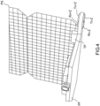
- the PF platform may also include an arm BR forming an extension of the PF platform in the plane of the PF platform.
- the BR arm visible in particular on the Figure 5 , makes it possible to further reduce the “scattering” phenomenon caused by the PS solar panel, even if the arm is not perfectly aligned with the edge of the solar panel, compared to the case where the antenna system is arranged at an angle of the platform, at the foot of the PS solar panel.
- the arm BR is arranged along an axis AX ( Figure 3 ) corresponding to the junction between the PF platform and the PS solar panel.
- the antenna system is then placed on said arm BR of the platform PF, it being understood that the earth remote control antenna Rx+Z and the anti-earth remote control antenna Rx-Z are arranged on either side of the arm BR .
- the BR arm forms an extension of the PF platform; the thickness of the arm corresponds to the thickness of the PF platform. In this way, the antennas of the same antenna pair (telemetry or remote control antennas) remain well spaced at a distance less than ⁇ .
- a deployment device DD of the arm BR illustrated by the figure 8 . It is important to ensure the reliability of BR arm deployment when the satellite is in orbit. Indeed, the back-to-back configuration of the antennas has the consequence that in the event of deployment failure, one of the two antennas could be completely unusable, which could interfere with the remote control or telemetry link.
- the DD deployment device can be equipped with a low-shock passive system.
- a low-shock passive system is a deployment system using one or more springs, as opposed to an active system, classically composed of a stepper motor. In a system passive low shock, it is the tension in the spring which allows the deployment of the structure.
- the invention thus makes it possible to improve the performance of Equivalent Isotropic Radiated Power (EIRP) in transmission, and the figure of merit (G/T) in reception, by offering better stability of the signal with the change in attitude of the platform. , and thus increasing the addressable field of view (no oscillations in a certain angular range).
- EIRP Equivalent Isotropic Radiated Power
- G/T figure of merit
- the invention makes it possible to reduce the power of the transponder, which makes it possible to have less heat dissipation, and to be able to integrate a more competitive amplification system.
- the power being reduced, the corona effect is less restrictive.
Landscapes
- Engineering & Computer Science (AREA)
- Remote Sensing (AREA)
- Aviation & Aerospace Engineering (AREA)
- Physics & Mathematics (AREA)
- Astronomy & Astrophysics (AREA)
- General Physics & Mathematics (AREA)
- Life Sciences & Earth Sciences (AREA)
- Sustainable Development (AREA)
- Computer Networks & Wireless Communication (AREA)
- Signal Processing (AREA)
- Details Of Aerials (AREA)
- Radio Relay Systems (AREA)
- Photovoltaic Devices (AREA)
- Chemical & Material Sciences (AREA)
- Combustion & Propulsion (AREA)
- Radar, Positioning & Navigation (AREA)
- Sustainable Energy (AREA)
- Thermal Sciences (AREA)
Claims (7)
- Satellit (SAT), umfassend eine Plattform (PF), mindestens ein Solarpaneel (PS) zur Versorgung des Satelliten (SAT) mit elektrischer Energie, wobei das Solarpaneel (PS) entlang einer Seite der Plattform (PF) befestigt ist, wobei der Satellit ein Antennensystem (Rx+Z, Rx-Z, Tx+Z, Tx-Z) umfasst, das zwei Fernsteuerungsantennen (Rx+Z, Rx-Z) und zwei Telemetrieantennen (Tx+Z, Tx-Z) umfasst, dadurch gekennzeichnet, dass:- die beiden Fernsteuerungsantennen (Rx+Z, Rx-Z) Rücken an Rücken auf beiden Seiten der Plattform angeordnet sind und einen Abstand voneinander aufweisen, der kleiner als oder gleich λ, ist, wobei λ der Wellenlänge des Fernsteuerungs- oder Telemetriesignals entspricht,- die beiden Fernsteuerungsantennen (Tx+Z, Tx-Z) Rücken an Rücken auf beiden Seiten der Plattform angeordnet sind und einen Abstand voneinander aufweisen, der kleiner als oder gleich λ ist,- das Antennensystem an einem der beiden Enden der Seite der Plattform (PF) angeordnet ist, an der das Solarpaneel (PS) befestigt ist.
- Satellit nach Anspruch 1, wobei die Plattform (PF) einen Transponder (TP) umfasst, wobei der Transponder (TP) an das Antennensystem (Rx+Z, Rx-Z, Tx+Z, Tx-Z) angrenzt.
- Satellit nach Anspruch 2, wobei die beiden Fernsteuerungsantennen (Rx+Z, Rx-Z) zwischen dem Transponder (TP) und den beiden Telemetrieantennen (Tx+Z, Tx-Z) angeordnet sind.
- Satellit nach Anspruch 2, wobei der Transponder (TP) zwischen den beiden Fernsteuerungsantennen (Rx+Z, Rx-Z) und den beiden Telemetrieantennen (Tx+Z, Tx-Z) angeordnet ist.
- Satellit nach einem der vorhergehenden Ansprüche, wobei die Plattform (PF) einen Arm umfasst, der eine Verlängerung der Plattform (PF) in der Ebene der Plattform (PF) bildet, entlang einer Achse (AX), die der Verbindung zwischen der Plattform (PF) und dem Solarpaneel (PS) entspricht, wobei das Antennensystem (Rx+Z, Rx-Z, Tx+Z, Tx-Z) auf dem Arm (BR) der Plattform (PF) angeordnet ist.
- Satellit nach Anspruch 5, wobei der Arm (BR) der Plattform eine Entfaltungsvorrichtung (DD) umfasst, wobei die Entfaltungsvorrichtung (DD) mit einem passiven Low-impact-System ausgestattet ist.
- Satellit nach einem der vorhergehenden Ansprüche, wobei der Satellit einen ersten Koppler (CPRx) umfasst, der konfiguriert ist, um Signale von den Fernsteuerungsantennen (Rx+Z, Rx-Z) zu addieren, einen zweiten Koppler (CPTx), der konfiguriert ist, um ein Telemetriesignal an die Fernsteuerungsantennen (Tx+Z, Tx-Z) zu übertragen, wobei der erste Koppler (CPRx) und der zweite Koppler (CPTx) zwischen die Fernsteuerungsantennen (Rx+Z, Rx-Z) bzw. zwischen die Fernsteuerungsantennen (Tx+Z, Tx-Z) geschaltet sind.
Applications Claiming Priority (1)
| Application Number | Priority Date | Filing Date | Title |
|---|---|---|---|
| FR2113212A FR3130393B1 (fr) | 2021-12-09 | 2021-12-09 | Agencement d'antennes TTC pour satellite plat |
Publications (2)
| Publication Number | Publication Date |
|---|---|
| EP4194344A1 EP4194344A1 (de) | 2023-06-14 |
| EP4194344B1 true EP4194344B1 (de) | 2024-06-12 |
Family
ID=81328590
Family Applications (1)
| Application Number | Title | Priority Date | Filing Date |
|---|---|---|---|
| EP22211875.4A Active EP4194344B1 (de) | 2021-12-09 | 2022-12-07 | Ttc-antennenanordnung für einen flachen satelliten |
Country Status (4)
| Country | Link |
|---|---|
| US (1) | US20230182924A1 (de) |
| EP (1) | EP4194344B1 (de) |
| CA (1) | CA3183563A1 (de) |
| FR (1) | FR3130393B1 (de) |
Family Cites Families (4)
| Publication number | Priority date | Publication date | Assignee | Title |
|---|---|---|---|---|
| US5152482A (en) * | 1990-06-29 | 1992-10-06 | Standard Space Platforms Corp. | Modular mother satellite bus for subsidiary payloads |
| FR2788179B1 (fr) * | 1998-12-31 | 2003-06-20 | Cit Alcatel | Satellite a couverture omnidirectionnelle |
| FR2789652B1 (fr) * | 1999-02-16 | 2001-04-13 | Matra Marconi Space France | Satellite utilisable en orbite basse, en particulier satellite de telecommunications |
| US10532830B2 (en) * | 2016-06-09 | 2020-01-14 | The Boeing Company | Stackable pancake satellite |
-
2021
- 2021-12-09 FR FR2113212A patent/FR3130393B1/fr active Active
-
2022
- 2022-12-06 US US18/076,331 patent/US20230182924A1/en active Pending
- 2022-12-07 EP EP22211875.4A patent/EP4194344B1/de active Active
- 2022-12-08 CA CA3183563A patent/CA3183563A1/en active Pending
Also Published As
| Publication number | Publication date |
|---|---|
| US20230182924A1 (en) | 2023-06-15 |
| FR3130393A1 (fr) | 2023-06-16 |
| EP4194344A1 (de) | 2023-06-14 |
| FR3130393B1 (fr) | 2023-11-03 |
| CA3183563A1 (en) | 2023-06-09 |
Similar Documents
| Publication | Publication Date | Title |
|---|---|---|
| EP2532046B1 (de) | Flachplatten-abtastantenne für landfahrzeuganwendung, fahrzeug mit einer solchen antenne und satellitentelekommunikationssystem mit solch einem fahrzeug | |
| EP2532050B1 (de) | Bordinterne direktionale flachplattenantenne, fahrzeug mit einer solchen antenne und satellitentelekommunikationssystem mit einem solchen fahrzeug | |
| EP0374008B1 (de) | Den vollen Raumwinkel abtastende elektronische Antenne mit räumlich zufällig verteilten, verdünnt angeordneten Strahlern | |
| EP2716549B1 (de) | Satellit mit ausfahrbaren Nutzlastlademodulen | |
| FR2517626A1 (fr) | Engin spatial orbital, notamment satellite, a missions multiples | |
| WO2008080894A1 (fr) | Antenne reseau rayonnant reconfigurable | |
| CA2290676A1 (fr) | Antenne pour systeme de telecommunication et procede d'emission ou reception a l'aide d'une telle antenne | |
| FR2760919A1 (fr) | Systeme de communication par satellite mobile | |
| EP0992128B1 (de) | Telekommunikationsanordnung | |
| EP1291962A1 (de) | Gruppenantennenstrahlformer für Raumfahrzeug | |
| EP4194344B1 (de) | Ttc-antennenanordnung für einen flachen satelliten | |
| FR2727934A1 (fr) | Satellite geostationnaire stabilise 3-axes a surveillance radar de son espace environnant | |
| CA3141789C (fr) | Vehicule spatial, lanceur et empilement de vehicules spatiaux | |
| FR2814614A1 (fr) | Lentille divergente a dome pour ondes hyperfrequences et antenne comportant une telle lentille | |
| EP3902059B1 (de) | Breitband-richtantenne mit longitudinalwellen-übertragung | |
| EP1142063A1 (de) | Telekommunikationsgerät mit geformter gruppenantenne unter verwendung von elektronischer strahlschwenkung und dazugehöriges telekommunikations-endgerät | |
| EP3416238B1 (de) | Sende- und empfangsanordnung für eine mehrfachstrahlantenne, und mehrfachstrahlantenne | |
| FR3073347A1 (fr) | Charge utile de satellite comportant un reflecteur a double surface reflechissante | |
| FR3102311A1 (fr) | Antenne-reseau | |
| EP1339177B1 (de) | Antennensystem zur Verbindung zwischen einem Fahrzeug und einer Luchtplattform, entsprechendes Verfahren und Systemverwendung | |
| WO2010043652A1 (fr) | Structure deployable et systeme antennaire a membranes comprenant une telle structure | |
| WO2015079037A2 (fr) | Agencement de structures antennaires pour télécommunications par satellites | |
| EP2889955A1 (de) | Kompaktantennenstruktur für Telekommunikationen über Satelliten |
Legal Events
| Date | Code | Title | Description |
|---|---|---|---|
| PUAI | Public reference made under article 153(3) epc to a published international application that has entered the european phase |
Free format text: ORIGINAL CODE: 0009012 |
|
| STAA | Information on the status of an ep patent application or granted ep patent |
Free format text: STATUS: THE APPLICATION HAS BEEN PUBLISHED |
|
| AK | Designated contracting states |
Kind code of ref document: A1 Designated state(s): AL AT BE BG CH CY CZ DE DK EE ES FI FR GB GR HR HU IE IS IT LI LT LU LV MC ME MK MT NL NO PL PT RO RS SE SI SK SM TR |
|
| STAA | Information on the status of an ep patent application or granted ep patent |
Free format text: STATUS: REQUEST FOR EXAMINATION WAS MADE |
|
| 17P | Request for examination filed |
Effective date: 20231102 |
|
| RBV | Designated contracting states (corrected) |
Designated state(s): AL AT BE BG CH CY CZ DE DK EE ES FI FR GB GR HR HU IE IS IT LI LT LU LV MC ME MK MT NL NO PL PT RO RS SE SI SK SM TR |
|
| GRAP | Despatch of communication of intention to grant a patent |
Free format text: ORIGINAL CODE: EPIDOSNIGR1 |
|
| STAA | Information on the status of an ep patent application or granted ep patent |
Free format text: STATUS: GRANT OF PATENT IS INTENDED |
|
| RIC1 | Information provided on ipc code assigned before grant |
Ipc: H04B 7/185 20060101ALN20231221BHEP Ipc: B64G 1/66 20060101ALI20231221BHEP Ipc: B64G 1/44 20060101ALI20231221BHEP Ipc: B64G 1/10 20060101AFI20231221BHEP |
|
| INTG | Intention to grant announced |
Effective date: 20240119 |
|
| GRAS | Grant fee paid |
Free format text: ORIGINAL CODE: EPIDOSNIGR3 |
|
| GRAA | (expected) grant |
Free format text: ORIGINAL CODE: 0009210 |
|
| STAA | Information on the status of an ep patent application or granted ep patent |
Free format text: STATUS: THE PATENT HAS BEEN GRANTED |
|
| AK | Designated contracting states |
Kind code of ref document: B1 Designated state(s): AL AT BE BG CH CY CZ DE DK EE ES FI FR GB GR HR HU IE IS IT LI LT LU LV MC ME MK MT NL NO PL PT RO RS SE SI SK SM TR |
|
| RAP3 | Party data changed (applicant data changed or rights of an application transferred) |
Owner name: THALES |
|
| REG | Reference to a national code |
Ref country code: GB Ref legal event code: FG4D Free format text: NOT ENGLISH |
|
| REG | Reference to a national code |
Ref country code: CH Ref legal event code: EP |
|
| REG | Reference to a national code |
Ref country code: IE Ref legal event code: FG4D Free format text: LANGUAGE OF EP DOCUMENT: FRENCH |
|
| REG | Reference to a national code |
Ref country code: DE Ref legal event code: R096 Ref document number: 602022003940 Country of ref document: DE |