EP4192033A1 - Electronic device - Google Patents
Electronic device Download PDFInfo
- Publication number
- EP4192033A1 EP4192033A1 EP21850529.5A EP21850529A EP4192033A1 EP 4192033 A1 EP4192033 A1 EP 4192033A1 EP 21850529 A EP21850529 A EP 21850529A EP 4192033 A1 EP4192033 A1 EP 4192033A1
- Authority
- EP
- European Patent Office
- Prior art keywords
- heat sink
- battery
- disposed
- antenna
- speaker module
- Prior art date
- Legal status (The legal status is an assumption and is not a legal conclusion. Google has not performed a legal analysis and makes no representation as to the accuracy of the status listed.)
- Granted
Links
Images


Classifications
-
- G—PHYSICS
- G06—COMPUTING OR CALCULATING; COUNTING
- G06F—ELECTRIC DIGITAL DATA PROCESSING
- G06F1/00—Details not covered by groups G06F3/00 - G06F13/00 and G06F21/00
- G06F1/16—Constructional details or arrangements
- G06F1/1613—Constructional details or arrangements for portable computers
- G06F1/1633—Constructional details or arrangements of portable computers not specific to the type of enclosures covered by groups G06F1/1615 - G06F1/1626
- G06F1/1635—Details related to the integration of battery packs and other power supplies such as fuel cells or integrated AC adapter
-
- H—ELECTRICITY
- H04—ELECTRIC COMMUNICATION TECHNIQUE
- H04R—LOUDSPEAKERS, MICROPHONES, GRAMOPHONE PICK-UPS OR LIKE ACOUSTIC ELECTROMECHANICAL TRANSDUCERS; ELECTRIC HEARING AIDS; PUBLIC ADDRESS SYSTEMS
- H04R9/00—Transducers of moving-coil, moving-strip, or moving-wire type
- H04R9/02—Details
- H04R9/022—Cooling arrangements
-
- G—PHYSICS
- G06—COMPUTING OR CALCULATING; COUNTING
- G06F—ELECTRIC DIGITAL DATA PROCESSING
- G06F1/00—Details not covered by groups G06F3/00 - G06F13/00 and G06F21/00
- G06F1/16—Constructional details or arrangements
- G06F1/1613—Constructional details or arrangements for portable computers
- G06F1/1633—Constructional details or arrangements of portable computers not specific to the type of enclosures covered by groups G06F1/1615 - G06F1/1626
- G06F1/1684—Constructional details or arrangements related to integrated I/O peripherals not covered by groups G06F1/1635 - G06F1/1675
-
- G—PHYSICS
- G06—COMPUTING OR CALCULATING; COUNTING
- G06F—ELECTRIC DIGITAL DATA PROCESSING
- G06F1/00—Details not covered by groups G06F3/00 - G06F13/00 and G06F21/00
- G06F1/16—Constructional details or arrangements
- G06F1/20—Cooling means
- G06F1/203—Cooling means for portable computers, e.g. for laptops
-
- H—ELECTRICITY
- H01—ELECTRIC ELEMENTS
- H01Q—ANTENNAS, i.e. RADIO AERIALS
- H01Q1/00—Details of, or arrangements associated with, antennas
- H01Q1/12—Supports; Mounting means
- H01Q1/22—Supports; Mounting means by structural association with other equipment or articles
- H01Q1/24—Supports; Mounting means by structural association with other equipment or articles with receiving set
- H01Q1/241—Supports; Mounting means by structural association with other equipment or articles with receiving set used in mobile communications, e.g. GSM
- H01Q1/242—Supports; Mounting means by structural association with other equipment or articles with receiving set used in mobile communications, e.g. GSM specially adapted for hand-held use
- H01Q1/243—Supports; Mounting means by structural association with other equipment or articles with receiving set used in mobile communications, e.g. GSM specially adapted for hand-held use with built-in antennas
-
- H—ELECTRICITY
- H04—ELECTRIC COMMUNICATION TECHNIQUE
- H04R—LOUDSPEAKERS, MICROPHONES, GRAMOPHONE PICK-UPS OR LIKE ACOUSTIC ELECTROMECHANICAL TRANSDUCERS; ELECTRIC HEARING AIDS; PUBLIC ADDRESS SYSTEMS
- H04R9/00—Transducers of moving-coil, moving-strip, or moving-wire type
- H04R9/06—Loudspeakers
-
- H—ELECTRICITY
- H04—ELECTRIC COMMUNICATION TECHNIQUE
- H04R—LOUDSPEAKERS, MICROPHONES, GRAMOPHONE PICK-UPS OR LIKE ACOUSTIC ELECTROMECHANICAL TRANSDUCERS; ELECTRIC HEARING AIDS; PUBLIC ADDRESS SYSTEMS
- H04R2499/00—Aspects covered by H04R or H04S not otherwise provided for in their subgroups
- H04R2499/10—General applications
- H04R2499/11—Transducers incorporated or for use in hand-held devices, e.g. mobile phones, PDA's, camera's
Definitions
- This application pertains to the field of communications technologies, and in particular, to an electronic device.
- a conventional solution is to dispose a heat sink on a magnetic isolation sheet (a part of a speaker's structure), a BOX profile steel sheet, and a battery of the speaker, to conduct the heat generated by the speaker to the battery, so as to achieve heat dissipation of a speaker module.
- the common heat sink due to conductivity of a common heat sink, the common heat sink will form parasitic capacitance with a conductive layer inside an electronic device, and the parasitic capacitance will generate resonance with an antenna around the speaker, which will affect transceiving performance of the antenna around the speaker.
- Embodiments of this application are intended to provide an electronic device, which can resolve a problem that parasitic capacitance generated by a heat sink interferes with an antenna.
- an embodiment of this application provides an electronic device, including a housing, a battery, an antenna, a speaker module, and a heat sink, where the battery, the antenna, the speaker module, and the heat sink are all disposed in a cavity formed by the housing; the battery and the speaker module are disposed adjacent to each other, and a gap exists between the battery and the speaker module; and the heat sink is disposed on the speaker module and the battery, and an opening is disposed on the heat sink, where the opening is opposite to the gap.
- the battery, the antenna, the speaker module, and the heat sink are all disposed in the cavity formed by the housing, where the battery and the speaker module are disposed adjacent to each other, and the antenna is disposed on a periphery of an area where the battery and the speaker module are located.
- a heat sink may be stuck in design of a front end structure. Therefore, due to conductivity of the heat sink, the heat sink will form parasitic capacitance with a conductive layer inside an electronic device, and the parasitic capacitance will generate resonance with an antenna around the speaker, which will affect transceiving performance of the antenna around the speaker.
- this application provides an electronic device, including a housing 1, a battery 2, an antenna 6, a speaker module, and a heat sink 3, where the battery 2, the antenna 6, the speaker module, and the heat sink 3 are all disposed in a cavity formed by the housing 1, the battery 2 and the speaker module are disposed adjacent to each other, a gap exists between the battery 2 and the speaker module, and the antenna 6 is disposed on a periphery of an area where the battery and the speaker module are located; and the heat sink 3 is disposed on the speaker module and the battery 2, where the heat sink 3 is provided with an opening, and the opening is opposite to the gap.
- a material with good thermal conductivity is selected for the heat sink 3.
- thermally conductive materials such as thermally conductive glue, thermally conductive silicone grease, and a thermally conductive silica gel sheet, feature advantages of good thermal conductivity, flexibility, and the like. It can be ensured that a thermally conductive material can fully fill a gap of a contact surface under the condition of a relatively low installation pressure, to reduce thermal resistance between the heat sink 3 and the contact surface, thereby improving heat dissipation efficiency.
- the heat sink is a graphene heat sink.
- the graphene heat sink has excellent heat conduction capability, which can not only conduct heat well in a direction in which the speaker module is opposite to the battery 2, but also conduct heat in a longitudinal direction perpendicular to a plane. Therefore, the graphene heat sink facilitates heat conduction. In addition, the graphene heat sink itself features excellent flexibility, which can be stuck to a functional device well, so as to meet heat dissipation and installation requirements.
- a metal (such as magnesium alloy, aluminum alloy, or n alloy) plate is disposed under a display screen of the electronic device.
- the graphene heat sink is stuck to the speaker module and the battery 2, there is a certain height difference between the graphene heat sink and the metal plate, so that the graphene heat sink and the metal plate are similar to two polar plates, and the metal plate is equivalent to a reference ground plane.
- the metal plate is equivalent to a reference ground plane.
- high-frequency parasitic capacitance will be formed between the graphene heat sink with conductivity and the reference ground plane, and a parasitic antenna will be derived.
- the formed parasitic capacitance will be greater, and the derived parasitic antenna will generate a resonance frequency, which will have an unacceptable impact on antenna performance.
- a large area of the heat sink 3 is stuck to the speaker module and the battery 2, to conduct heat generated by the speaker module to the battery through the heat sink 3, so that heat dissipation of the speaker module can be implemented.
- the formed parasitic resonance may be removed from an operating frequency band of the antenna, so that the influence of the parasitic capacitance formed by the heat sink 3 on the antenna can be reduced. Therefore, transceiving performance of the antenna is not affected while an audio playing effect of the speaker module can be ensured, thereby improving use experience of the user.
- the antenna 6 includes a high-frequency antenna, an intermediate-frequency antenna, and a low-frequency antenna.
- the high-frequency antenna and the intermediate-frequency antenna are disposed on a first side the speaker module, where the first side is a side far away from the battery 2, and the low-frequency antenna is disposed on a second side, and the second side is adjacent to the first side.
- the housing 1 includes a middle frame, and the first side is an inner side that is of the middle frame and that is close to the speaker module.
- the high-frequency antenna and the intermediate-frequency antenna are disposed at an edge position that is in the inner side of the middle frame 1 and that is close to the speaker module. It can be understood that the parasitic antenna formed by the heat sink 3 in this environment will greatly influence the performance of the high-frequency antenna and the intermediate-frequency antenna on the first side.
- the parasitic resonance formed by the heat sink 3 can be removed from operating frequency bands of the high-frequency antenna and the intermediate-frequency antenna, thereby reducing the influence of the parasitic capacitance on the transceiving performance of the antenna.
- a size of the opening is related to a position for disposing the antenna 6.
- a structure of the antenna 6 is designed and laid out according to an intermediate frequency and a high frequency, and a length and width of the opening on the heat sink 3 may be determined based on the position for disposing the antenna 6 and according to the influence of simulated coupling.
- a length direction of the opening corresponds to an extension direction of the gap between the battery and the speaker module, and a width direction of the opening corresponds to a width direction of the gap.
- the speaker module includes a steel sheet 5 and a magnetic isolation sheet 4, a gap formed between the magnetic isolation sheet 4 and the battery 2 is a first gap, and a first opening 301 on the heat sink is disposed 3 opposite to the first gap.
- the magnetic isolation sheet 4 is a kind of magnetic sheet with great magnetic permeability, which is soft in texture and covered with adhesive glue on one side. Such magnetic sheet can be made into different thicknesses according to different applications, and can be die-cut into a required size and shape.
- the magnetic insulation sheet absorbs electromagnetic wave energy and converts the electromagnetic wave energy into heat energy by using electronic scattering caused by thermal motion of a functional component in a lattice electric field and interaction between electrons, so as to achieve a purpose of attenuating the electromagnetic wave.
- the steel sheet 5 is a BOX profile steel sheet, a thickness of the BOX profile steel sheet is 0.2mm, and a thickness of a plastic cement BOX is 0.5mm.
- the use of the BOX profile steel sheet can reduce the thickness of the whole device by 0.3mm, so as to design a horn cavity structure, so that a volume of a sound cavity can be increased, and a good sound playing effect of the speaker of the whole device can be achieved.
- the heat sink 3 has a structure disposed with an opening on a single side, that is, the opening is disposed that is on the heat sink 3 and that is only at a gap between the magnetic isolation sheet 4 and the battery 2, but no opening is disposed at a gap between the steel sheet 5 and the battery 2. Because a graphite heat sink and a metal plate under a display screen form two plates of capacitance, as a height difference between the graphite heat sink and the metal plate is larger, formed parasitic capacitance will be greater, and then interference with transceiving performance of an antenna 6 will be greater. On a terminal product, a distance between an area between the magnetic isolation sheet and the battery and the metal plate under the display screen is the largest, which has the greatest interference with the antenna 6. Therefore, an opening disposed at the gap between the magnetic isolation sheet 4 and the battery 2 can effectively reduce generation of the parasitic capacitance, and then the transceiving performance of the antenna 6 can be improved.
- a gap formed between the steel sheet 5 and the battery 2 is a second gap, and a second opening 302 on the heat sink 3 is disposed at a position opposite to the second gap.
- the heat sink 3 has a structure disposed with two openings on two sides, that is, a first opening is disposed for the heat sink 3 at a gap between a magnetic isolation sheet 4 and the battery 2, and a second opening is disposed at a gap between the steel sheet 5 and the battery 2.
- Heat generated by a speaker module is conducted to a battery side through a connecting part that is of the heat sink 3 and that is between the first opening 301 and the second opening 302.
- the structure disposed with the two openings on two sides of the heat sink 3 is disposed to eliminate an influence of parasitic capacitance on an antenna 6, which cannot be eliminated by a structure disposed with one opening on one side.
- the magnetic isolation sheet 4 is suspended above a sound cavity of the speaker module.
- the electronic device includes a display screen, and a metal plate is disposed under the display screen.
- the steel sheet 5 and the metal plate are connected by a single bolt, so that the steel sheet 5 can be connected by single-point grounding.
- the steel sheet 5 is connected to the metal plate through multiple bolts, so that the steel sheet 5 can be connected by even grounding.
- the steel sheet 5 is suspended on a side that is of the speaker module and that is away from the metal plate, so that the steel sheet 5 can be connected by no grounding.
- an insulation layer is disposed between the magnetic isolation sheet 4 and the heat sink 3.
- the insulation layer has little influence on temperature rise of the speaker module, so as to further reduce the influence of the parasitic capacitance formed by the heat sink 3 on the performance of the antenna 6.
- the insulation layer is a thermally conductive insulation layer.
- the insulation layer may be a PET insulation layer.
- the PET commonly known as polyester resin, belongs to crystalline saturated polyesters, and is a milky white or light yellow, and highly crystallographic polymer with a smooth and shiny surface, and is characterized with creep resistance, fatigue resistance, abrasion resistance, good dimensional stability, little wear, and high hardness.
- a thickness of the insulation layer is not less than 0.1mm. This way, if space allows, the coupling path of the parasitic antenna may be better reduced, thus reducing the influence of the parasitic capacitance on the performance of antenna 6.
- the housing 1 is provided with a heat dissipation interlayer on a side close to the speaker module.
- a side that is of the housing 1 and that is close to the speaker module is disposed as a heat dissipation interlayer structure, such as that a slice layer made of graphene or copper with good thermal conductivity is disposed at a position that is on the housing 1 and that is opposite to the speaker module.
- heat generated by the speaker module may be directly dissipated through the housing 1, so that a heat dissipation path can be increased, and then heat dissipation performance of the speaker module can be better improved, and strength and toughness of the housing 1 can be enhanced.
Landscapes
- Engineering & Computer Science (AREA)
- Physics & Mathematics (AREA)
- Theoretical Computer Science (AREA)
- Computer Hardware Design (AREA)
- Signal Processing (AREA)
- Acoustics & Sound (AREA)
- Human Computer Interaction (AREA)
- General Engineering & Computer Science (AREA)
- General Physics & Mathematics (AREA)
- Computer Networks & Wireless Communication (AREA)
- Power Engineering (AREA)
- Shielding Devices Or Components To Electric Or Magnetic Fields (AREA)
- Cooling Or The Like Of Electrical Apparatus (AREA)
Abstract
Description
- This application claims priority to
Chinese Patent Application No. 202010737350.1 filed in China on July 28, 2020 - This application pertains to the field of communications technologies, and in particular, to an electronic device.
- With the development of smart terminals, sound playing by an audio speaker of a smart terminal is applied to more scenarios. Power for the speaker to work is converted into heat. In an increasing number of application scenarios, heat is concentrated at the speaker, resulting in that the speaker is hot.
- In the related art, to resolve the problem of heat generation by the speaker, a conventional solution is to dispose a heat sink on a magnetic isolation sheet (a part of a speaker's structure), a BOX profile steel sheet, and a battery of the speaker, to conduct the heat generated by the speaker to the battery, so as to achieve heat dissipation of a speaker module. However, due to conductivity of a common heat sink, the common heat sink will form parasitic capacitance with a conductive layer inside an electronic device, and the parasitic capacitance will generate resonance with an antenna around the speaker, which will affect transceiving performance of the antenna around the speaker.
- Embodiments of this application are intended to provide an electronic device, which can resolve a problem that parasitic capacitance generated by a heat sink interferes with an antenna.
- To resolve the foregoing technical problem, this application is implemented as follows.
- According to a first aspect, an embodiment of this application provides an electronic device, including a housing, a battery, an antenna, a speaker module, and a heat sink, where the battery, the antenna, the speaker module, and the heat sink are all disposed in a cavity formed by the housing; the battery and the speaker module are disposed adjacent to each other, and a gap exists between the battery and the speaker module; and
the heat sink is disposed on the speaker module and the battery, and an opening is disposed on the heat sink, where the opening is opposite to the gap. - In the embodiments of this application, the battery, the antenna, the speaker module, and the heat sink are all disposed in the cavity formed by the housing, where the battery and the speaker module are disposed adjacent to each other, and the antenna is disposed on a periphery of an area where the battery and the speaker module are located. By disposing the heat sink on the speaker module and the battery, heat generated by the speaker module can be conducted to a battery side, thus implementing heat dissipation. Further, by disposing an opening on the heat sink at a position just opposite to a gap between the battery and the speaker module, parasitic resonance formed by the heat sink can be removed from an operating frequency band of the antenna. Therefore, interference with transceiving performance of the antenna can be reduced while an audio playing effect of the speaker module can be ensured.
-
-
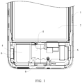
FIG. 1 is a first schematic structural diagram of an electronic device according to an embodiment of the present invention; -
FIG. 2 is a second schematic structural diagram of the electronic device according to an embodiment of the present invention; and -
FIG. 3 is a third schematic structural diagram of the electronic device according to an embodiment of the present invention. - Reference numerals in the accompanying drawings:
1-Housing; 2- Battery; 3-Heat sink; 301-First opening; 302-Second opening; 4-Magnetic isolation sheet; 5-Steel sheet; 6-Antenna. - The following clearly and completely describes the technical solutions in the embodiments of this application with reference to the accompanying drawings in the embodiments of this application. Apparently, the described embodiments are some but not all of the embodiments of this application. All other embodiments obtained by a person of ordinary skill in the art based on the embodiments of this application without creative efforts shall fall within the protection scope of this application.
- The terms "first", "second", and the like in the specification and claims of this application are used to distinguish between similar objects instead of describing a specific order or sequence. It should be understood that the data used in this way is interchangeable in appropriate circumstances so that the embodiments of this application can be implemented in other orders than the order illustrated or described herein. In addition, in the specification and the claims, "and/or" represents at least one of connected objects, and a character "/" generally represents an "or" relationship between associated objects.
- To resolve the foregoing problem, in this application, in consideration of an antenna standard, the influence of a heat sink on an antenna, a difference in structural design, and the like, a heat sink may be stuck in design of a front end structure. Therefore, due to conductivity of the heat sink, the heat sink will form parasitic capacitance with a conductive layer inside an electronic device, and the parasitic capacitance will generate resonance with an antenna around the speaker, which will affect transceiving performance of the antenna around the speaker.
- With reference to the accompanying drawings, an electronic device provided in the embodiments of this application will be described in detail by using specific examples and application scenarios thereof.
- Referring to
FIG. 1 to FIG. 3 , this application provides an electronic device, including ahousing 1, abattery 2, anantenna 6, a speaker module, and aheat sink 3, where thebattery 2, theantenna 6, the speaker module, and theheat sink 3 are all disposed in a cavity formed by thehousing 1, thebattery 2 and the speaker module are disposed adjacent to each other, a gap exists between thebattery 2 and the speaker module, and theantenna 6 is disposed on a periphery of an area where the battery and the speaker module are located; and theheat sink 3 is disposed on the speaker module and thebattery 2, where theheat sink 3 is provided with an opening, and the opening is opposite to the gap. - A material with good thermal conductivity is selected for the
heat sink 3. Commonly used thermally conductive materials, such as thermally conductive glue, thermally conductive silicone grease, and a thermally conductive silica gel sheet, feature advantages of good thermal conductivity, flexibility, and the like. It can be ensured that a thermally conductive material can fully fill a gap of a contact surface under the condition of a relatively low installation pressure, to reduce thermal resistance between theheat sink 3 and the contact surface, thereby improving heat dissipation efficiency. Optionally, the heat sink is a graphene heat sink. The graphene heat sink has excellent heat conduction capability, which can not only conduct heat well in a direction in which the speaker module is opposite to thebattery 2, but also conduct heat in a longitudinal direction perpendicular to a plane. Therefore, the graphene heat sink facilitates heat conduction. In addition, the graphene heat sink itself features excellent flexibility, which can be stuck to a functional device well, so as to meet heat dissipation and installation requirements. - It should be noted that a metal (such as magnesium alloy, aluminum alloy, or n alloy) plate is disposed under a display screen of the electronic device. After the graphene heat sink is stuck to the speaker module and the
battery 2, there is a certain height difference between the graphene heat sink and the metal plate, so that the graphene heat sink and the metal plate are similar to two polar plates, and the metal plate is equivalent to a reference ground plane. This way, high-frequency parasitic capacitance will be formed between the graphene heat sink with conductivity and the reference ground plane, and a parasitic antenna will be derived. In addition, as the height difference between the graphene heat sink and the reference ground plane is larger, the formed parasitic capacitance will be greater, and the derived parasitic antenna will generate a resonance frequency, which will have an unacceptable impact on antenna performance. - In this embodiment, a large area of the
heat sink 3 is stuck to the speaker module and thebattery 2, to conduct heat generated by the speaker module to the battery through theheat sink 3, so that heat dissipation of the speaker module can be implemented. Further, by disposing an opening on theheat sink 3 at a position is opposite to a gap between thebattery 2 and the speaker module, the formed parasitic resonance may be removed from an operating frequency band of the antenna, so that the influence of the parasitic capacitance formed by theheat sink 3 on the antenna can be reduced. Therefore, transceiving performance of the antenna is not affected while an audio playing effect of the speaker module can be ensured, thereby improving use experience of the user. - In an embodiment, the
antenna 6 includes a high-frequency antenna, an intermediate-frequency antenna, and a low-frequency antenna. The high-frequency antenna and the intermediate-frequency antenna are disposed on a first side the speaker module, where the first side is a side far away from thebattery 2, and the low-frequency antenna is disposed on a second side, and the second side is adjacent to the first side. - Specifically, the
housing 1 includes a middle frame, and the first side is an inner side that is of the middle frame and that is close to the speaker module. For example, the high-frequency antenna and the intermediate-frequency antenna are disposed at an edge position that is in the inner side of themiddle frame 1 and that is close to the speaker module. It can be understood that the parasitic antenna formed by theheat sink 3 in this environment will greatly influence the performance of the high-frequency antenna and the intermediate-frequency antenna on the first side. In this application, by disposing the opening on theheat sink 3 and enabling the opening to be opposite to the gap between thebattery 2 and the speaker module, the parasitic resonance formed by theheat sink 3 can be removed from operating frequency bands of the high-frequency antenna and the intermediate-frequency antenna, thereby reducing the influence of the parasitic capacitance on the transceiving performance of the antenna. - In an embodiment, a size of the opening is related to a position for disposing the
antenna 6. - It should be noted that a structure of the
antenna 6 is designed and laid out according to an intermediate frequency and a high frequency, and a length and width of the opening on theheat sink 3 may be determined based on the position for disposing theantenna 6 and according to the influence of simulated coupling. A length direction of the opening corresponds to an extension direction of the gap between the battery and the speaker module, and a width direction of the opening corresponds to a width direction of the gap. This way, based on the position for disposing theantenna 6, a proper opening size is set, which can minimize the influence of the parasitic capacitance on the performance of theantenna 6. - Referring to
FIG. 2 , in an embodiment, the speaker module includes a steel sheet 5 and amagnetic isolation sheet 4, a gap formed between themagnetic isolation sheet 4 and thebattery 2 is a first gap, and afirst opening 301 on the heat sink is disposed 3 opposite to the first gap. - It should be noted that the
magnetic isolation sheet 4 is a kind of magnetic sheet with great magnetic permeability, which is soft in texture and covered with adhesive glue on one side. Such magnetic sheet can be made into different thicknesses according to different applications, and can be die-cut into a required size and shape. The magnetic insulation sheet absorbs electromagnetic wave energy and converts the electromagnetic wave energy into heat energy by using electronic scattering caused by thermal motion of a functional component in a lattice electric field and interaction between electrons, so as to achieve a purpose of attenuating the electromagnetic wave. Further, in consideration of a design thickness of a whole device structure, the steel sheet 5 is a BOX profile steel sheet, a thickness of the BOX profile steel sheet is 0.2mm, and a thickness of a plastic cement BOX is 0.5mm. On the premise of ensuring the thickness of the whole device, the use of the BOX profile steel sheet can reduce the thickness of the whole device by 0.3mm, so as to design a horn cavity structure, so that a volume of a sound cavity can be increased, and a good sound playing effect of the speaker of the whole device can be achieved. - In this embodiment, the
heat sink 3 has a structure disposed with an opening on a single side, that is, the opening is disposed that is on theheat sink 3 and that is only at a gap between themagnetic isolation sheet 4 and thebattery 2, but no opening is disposed at a gap between the steel sheet 5 and thebattery 2. Because a graphite heat sink and a metal plate under a display screen form two plates of capacitance, as a height difference between the graphite heat sink and the metal plate is larger, formed parasitic capacitance will be greater, and then interference with transceiving performance of anantenna 6 will be greater. On a terminal product, a distance between an area between the magnetic isolation sheet and the battery and the metal plate under the display screen is the largest, which has the greatest interference with theantenna 6. Therefore, an opening disposed at the gap between themagnetic isolation sheet 4 and thebattery 2 can effectively reduce generation of the parasitic capacitance, and then the transceiving performance of theantenna 6 can be improved. - It should be noted that, compared with a method for sticking the
heat sink 3 disposed without an opening, structural design of sticking theheat sink 2 disposed with an opening can not only ensure heat dissipation performance, but also reduce the influence on the performance of theantenna 6. That is, the heat sink disposed with thefirst opening 301 and a heat sink disposed without thefirst opening 301 have almost same heat dissipation performance for the speaker module. However, because a position of the opening will not form capacitance with the metal plate under the display screen, an influence of the heat sink disposed with thefirst opening 301 on theantenna 6 disposed on a periphery of a middle frame can be greatly reduced compared with the heat sink disposed without thefirst opening 301. Therefore, in this embodiment, the influence of parasitic capacitance on the performance of theantenna 6 can be reduced without affecting the heat dissipation performance of the speaker module. - Further, as shown in
FIG. 3 , a gap formed between the steel sheet 5 and thebattery 2 is a second gap, and asecond opening 302 on theheat sink 3 is disposed at a position opposite to the second gap. - In this embodiment, the
heat sink 3 has a structure disposed with two openings on two sides, that is, a first opening is disposed for theheat sink 3 at a gap between amagnetic isolation sheet 4 and thebattery 2, and a second opening is disposed at a gap between the steel sheet 5 and thebattery 2. Heat generated by a speaker module is conducted to a battery side through a connecting part that is of theheat sink 3 and that is between thefirst opening 301 and thesecond opening 302. The structure disposed with the two openings on two sides of theheat sink 3 is disposed to eliminate an influence of parasitic capacitance on anantenna 6, which cannot be eliminated by a structure disposed with one opening on one side. - It should be noted that the
magnetic isolation sheet 4 is suspended above a sound cavity of the speaker module. The electronic device includes a display screen, and a metal plate is disposed under the display screen. The steel sheet 5 and the metal plate are connected by a single bolt, so that the steel sheet 5 can be connected by single-point grounding. Alternatively, the steel sheet 5 is connected to the metal plate through multiple bolts, so that the steel sheet 5 can be connected by even grounding. Alternatively, the steel sheet 5 is suspended on a side that is of the speaker module and that is away from the metal plate, so that the steel sheet 5 can be connected by no grounding. - In an embodiment, to reduce a coupling path of a parasitic antenna, an insulation layer is disposed between the
magnetic isolation sheet 4 and theheat sink 3. However, the insulation layer has little influence on temperature rise of the speaker module, so as to further reduce the influence of the parasitic capacitance formed by theheat sink 3 on the performance of theantenna 6. - Specifically, the insulation layer is a thermally conductive insulation layer. For example, the insulation layer may be a PET insulation layer. The PET, commonly known as polyester resin, belongs to crystalline saturated polyesters, and is a milky white or light yellow, and highly crystallographic polymer with a smooth and shiny surface, and is characterized with creep resistance, fatigue resistance, abrasion resistance, good dimensional stability, little wear, and high hardness.
- Further, a thickness of the insulation layer is not less than 0.1mm. This way, if space allows, the coupling path of the parasitic antenna may be better reduced, thus reducing the influence of the parasitic capacitance on the performance of
antenna 6. - In an embodiment, the
housing 1 is provided with a heat dissipation interlayer on a side close to the speaker module. For example, a side that is of thehousing 1 and that is close to the speaker module is disposed as a heat dissipation interlayer structure, such as that a slice layer made of graphene or copper with good thermal conductivity is disposed at a position that is on thehousing 1 and that is opposite to the speaker module. This way, heat generated by the speaker module may be directly dissipated through thehousing 1, so that a heat dissipation path can be increased, and then heat dissipation performance of the speaker module can be better improved, and strength and toughness of thehousing 1 can be enhanced. - It should be noted that in this specification, relationship terms such as "first" and "second" are merely used to distinguish one entity or operation from another, and do not necessarily require or imply that any actual relationship or sequence exists between these entities or operations. In addition, the terms "comprise", "include" and any other variants thereof are intended to cover non-exclusive inclusion, so that a process, a method, an article, or an apparatus that includes a series of elements not only includes these elements, but may also include other elements not expressly listed, or also include elements inherent to this process, method, article, or apparatus. An element limited by "includes a ..." does not, without more constraints, does not include the presence of additional identical elements in the process, method, article, or apparatus that includes the element.
- The embodiments of this application are described above with reference to the accompanying drawings, but this application is not limited to the foregoing specific implementations. The foregoing specific implementations are merely schematic instead of restrictive. Under enlightenment of this application, a person of ordinary skills in the art may make many forms without departing from aims and the protection scope of claims of this application, all of which fall within the protection scope of this application.
Claims (10)
- An electronic device, comprising a housing, a battery, an antenna, a speaker module, and a heat sink; wherein
the battery, the antenna, the speaker module, and the heat sink are all disposed in a cavity formed by the housing; the battery and the speaker module are disposed adjacent to each other, a gap exists between the battery and the speaker module, and the antenna is disposed on a periphery of an area where the battery and the speaker module are located; and the heat sink is disposed on the speaker module and the battery, and an opening is disposed on the heat sink, wherein the opening is opposite to the gap. - The electronic device according to claim 1, wherein the speaker module comprises a steel sheet and a magnetic isolation sheet, a gap formed between the magnetic isolation sheet and the battery is a first gap, and a first opening on the heat sink is disposed at a position opposite to the first gap.
- The electronic device according to claim 2, wherein a gap formed between the steel sheet and the battery is a second gap, and a second opening on the heat sink is disposed at a position opposite to the second gap.
- The electronic device according to claim 2, wherein an insulation layer is disposed between the magnetic isolation sheet and the heat sink.
- The electronic device according to claim 4, wherein the insulation layer is a thermally conductive insulation layer.
- The electronic device according to claim 4, wherein a thickness of the insulation layer is not less than 0.1mm.
- The electronic device according to claim 1, wherein the heat sink is a graphite heat sink.
- The electronic device according to claim 2, wherein the magnetic isolation sheet is suspended above a sound cavity of the speaker module.
- The electronic device according to claim 1, wherein a size of the opening is related to a position for disposing the antenna.
- The electronic device according to claim 9, wherein the antenna comprises a high-frequency antenna, an intermediate-frequency antenna, and a low-frequency antenna, wherein the high-frequency antenna and the intermediate-frequency antenna are disposed on a first side of the speaker module, wherein the first side is a side far away from the battery, and the low-frequency antenna is disposed on a second side, wherein the second side is adjacent to the first side.
Applications Claiming Priority (2)
| Application Number | Priority Date | Filing Date | Title |
|---|---|---|---|
| CN202010737350.1A CN111901733B (en) | 2020-07-28 | 2020-07-28 | Electronic device |
| PCT/CN2021/108622 WO2022022499A1 (en) | 2020-07-28 | 2021-07-27 | Electronic device |
Publications (3)
| Publication Number | Publication Date |
|---|---|
| EP4192033A1 true EP4192033A1 (en) | 2023-06-07 |
| EP4192033A4 EP4192033A4 (en) | 2024-01-24 |
| EP4192033B1 EP4192033B1 (en) | 2025-07-23 |
Family
ID=73190463
Family Applications (1)
| Application Number | Title | Priority Date | Filing Date |
|---|---|---|---|
| EP21850529.5A Active EP4192033B1 (en) | 2020-07-28 | 2021-07-27 | Electronic device |
Country Status (5)
| Country | Link |
|---|---|
| US (1) | US12366888B2 (en) |
| EP (1) | EP4192033B1 (en) |
| CN (1) | CN111901733B (en) |
| ES (1) | ES3037797T3 (en) |
| WO (1) | WO2022022499A1 (en) |
Families Citing this family (4)
| Publication number | Priority date | Publication date | Assignee | Title |
|---|---|---|---|---|
| CN111901733B (en) * | 2020-07-28 | 2021-10-12 | 维沃移动通信有限公司 | Electronic device |
| CN113381079B (en) * | 2021-06-08 | 2022-07-08 | 歌尔科技有限公司 | Winding type battery and TWS Bluetooth headset |
| CN113381078A (en) * | 2021-06-08 | 2021-09-10 | 歌尔科技有限公司 | Winding type battery and TWS Bluetooth headset |
| CN113999621B (en) * | 2021-10-29 | 2023-06-23 | 维沃移动通信有限公司 | Thermal film and electronic equipment |
Family Cites Families (42)
| Publication number | Priority date | Publication date | Assignee | Title |
|---|---|---|---|---|
| JP3516789B2 (en) * | 1995-11-15 | 2004-04-05 | 三菱電機株式会社 | Semiconductor power module |
| US6031492A (en) * | 1996-06-10 | 2000-02-29 | Ericsson Inc. | Mobile cradle antenna and heat sink enhancement |
| GB0122226D0 (en) * | 2001-09-13 | 2001-11-07 | Koninl Philips Electronics Nv | Wireless terminal |
| JP2005308978A (en) * | 2004-04-20 | 2005-11-04 | Fujitsu Hitachi Plasma Display Ltd | Display device |
| GB2440570A (en) * | 2006-07-28 | 2008-02-06 | Iti Scotland Ltd | Antenna and heat sink |
| US9070969B2 (en) * | 2010-07-06 | 2015-06-30 | Apple Inc. | Tunable antenna systems |
| WO2012024578A2 (en) * | 2010-08-19 | 2012-02-23 | Apple Inc. | Portable electronic device |
| WO2012124008A1 (en) * | 2011-03-16 | 2012-09-20 | パナソニック株式会社 | Antenna device |
| KR101873407B1 (en) * | 2011-07-13 | 2018-07-02 | 엘지전자 주식회사 | Mobile terminal |
| US20130229320A1 (en) * | 2011-10-06 | 2013-09-05 | Kenichi Asanuma | Small antenna apparatus operable in multiple bands including low-band frequency and high-band frequency and shifting low-band frequency to lower frequency |
| EP2725612A1 (en) * | 2012-10-29 | 2014-04-30 | TP Vision Holding B.V. | Heat conductor device and method of forming a heat conductor device |
| US9331397B2 (en) * | 2013-03-18 | 2016-05-03 | Apple Inc. | Tunable antenna with slot-based parasitic element |
| FR3029688B1 (en) * | 2014-12-03 | 2018-01-26 | Sagemcom Broadband Sas | ELECTRONIC DEVICE WITH ANTENNA INTEGRATED WITH A THERMAL DISSIPATOR |
| CN104601759B (en) * | 2015-02-02 | 2018-03-23 | 广东欧珀移动通信有限公司 | A kind of mobile phone radiator structure and mobile phone |
| GB201503426D0 (en) * | 2015-02-27 | 2015-04-15 | Native Design Ltd | Light and speaker driver device |
| KR102231232B1 (en) * | 2015-02-27 | 2021-03-23 | 삼성전자주식회사 | Antenna and electronic device having it |
| CN104902356A (en) * | 2015-03-31 | 2015-09-09 | 歌尔声学股份有限公司 | Speaker module |
| KR101723499B1 (en) * | 2015-07-15 | 2017-04-07 | 주식회사 테인엘티에스 | Heatsink comprising electro conductive push pin |
| CN105430124B (en) * | 2015-10-28 | 2019-03-05 | 努比亚技术有限公司 | A terminal and heat dissipation method |
| KR102476765B1 (en) * | 2015-12-15 | 2022-12-13 | 삼성전자주식회사 | Electronic Device with Antenna |
| CN205584479U (en) * | 2016-03-31 | 2016-09-14 | 歌尔声学股份有限公司 | Loudspeaker module group |
| CN106100662B (en) * | 2016-05-27 | 2018-11-09 | 上海传英信息技术有限公司 | Printed circuit board and wireless communication device with printed circuit board |
| CN106129595A (en) * | 2016-06-30 | 2016-11-16 | 大连楼兰科技股份有限公司 | A vehicle-mounted antenna with heat dissipation function |
| WO2018057645A1 (en) * | 2016-09-22 | 2018-03-29 | Apple Inc. | Battery architecture in an electronic device |
| WO2018168699A1 (en) * | 2017-03-14 | 2018-09-20 | 日本電気株式会社 | Heat-dissipation mechanism and wireless communication device |
| US10476167B2 (en) * | 2017-07-20 | 2019-11-12 | Apple Inc. | Adjustable multiple-input and multiple-output antenna structures |
| KR101958789B1 (en) * | 2017-07-28 | 2019-07-02 | 엘지전자 주식회사 | Mobile terminal |
| KR102468879B1 (en) * | 2017-08-31 | 2022-11-21 | 삼성전자주식회사 | Electronic apparatus including antenna using component of display pannel |
| CN207234896U (en) * | 2017-09-30 | 2018-04-13 | 深圳市新科盈数码有限公司 | Intercom back splint power supply |
| KR102593853B1 (en) * | 2017-12-29 | 2023-10-24 | 엘지디스플레이 주식회사 | Fingerprint sensing display apparatus |
| KR102469449B1 (en) * | 2018-02-09 | 2022-11-22 | 삼성전자주식회사 | Heat radiating structure and electronic device with the same |
| JP6587045B1 (en) * | 2018-02-21 | 2019-10-09 | 株式会社村田製作所 | ANTENNA DEVICE AND ELECTRONIC DEVICE |
| KR102091611B1 (en) * | 2018-06-11 | 2020-03-20 | 엘지전자 주식회사 | Mobile terminal |
| KR102706683B1 (en) * | 2018-11-23 | 2024-09-13 | 삼성전자 주식회사 | structure for shielding a magnetic force of speaker and electronic device including the same |
| CN109765069B (en) * | 2019-01-28 | 2021-09-07 | 晶晨半导体(深圳)有限公司 | Radiator testing method and system |
| CN109769341B (en) * | 2019-01-28 | 2022-01-21 | 晶晨半导体(深圳)有限公司 | Method for solving antenna effect of metal radiating fin |
| CN209659611U (en) * | 2019-05-24 | 2019-11-19 | 维沃移动通信有限公司 | Speaker, speaker assembly and mobile terminal |
| CN110389640B (en) * | 2019-07-03 | 2021-07-13 | 维沃移动通信有限公司 | A kind of heat dissipation method and mobile terminal |
| US11503143B2 (en) * | 2019-12-03 | 2022-11-15 | Apple Inc. | Handheld electronic device |
| CN111278258B (en) * | 2020-02-07 | 2022-05-31 | 联想(北京)有限公司 | Case and electronic equipment |
| CN111405829B (en) * | 2020-04-08 | 2022-06-03 | 深圳传音控股股份有限公司 | Heat dissipation structure, method and terminal |
| CN111901733B (en) * | 2020-07-28 | 2021-10-12 | 维沃移动通信有限公司 | Electronic device |
-
2020
- 2020-07-28 CN CN202010737350.1A patent/CN111901733B/en active Active
-
2021
- 2021-07-27 WO PCT/CN2021/108622 patent/WO2022022499A1/en not_active Ceased
- 2021-07-27 ES ES21850529T patent/ES3037797T3/en active Active
- 2021-07-27 EP EP21850529.5A patent/EP4192033B1/en active Active
-
2023
- 2023-01-18 US US18/098,682 patent/US12366888B2/en active Active
Also Published As
| Publication number | Publication date |
|---|---|
| CN111901733A (en) | 2020-11-06 |
| US12366888B2 (en) | 2025-07-22 |
| US20230176633A1 (en) | 2023-06-08 |
| WO2022022499A1 (en) | 2022-02-03 |
| ES3037797T3 (en) | 2025-10-06 |
| CN111901733B (en) | 2021-10-12 |
| EP4192033A4 (en) | 2024-01-24 |
| EP4192033B1 (en) | 2025-07-23 |
Similar Documents
| Publication | Publication Date | Title |
|---|---|---|
| EP4192033B1 (en) | Electronic device | |
| JP2017188601A (en) | Electronic apparatus | |
| CN109216874A (en) | Wearable device with antenna structure | |
| US20190104644A1 (en) | Electronic device | |
| CN109586365A (en) | Wireless charging device | |
| CN113140884B (en) | Heat radiation structure and terminal equipment with signal transmission function | |
| CN217936328U (en) | Shielding case cooling system and electronic equipment | |
| CN202889779U (en) | Single side printed wiring board with superelevation heat-conducting property | |
| KR102673634B1 (en) | Radar apparatus and thereof case structure | |
| CN210610139U (en) | Carbon fiber filled high-thermal-conductivity and electric-conductivity composite material | |
| CN211199101U (en) | A thermally conductive wave absorbing material | |
| JP4651411B2 (en) | ANTENNA DEVICE AND RADIO DEVICE | |
| CN206629268U (en) | Loudspeaker module and the electronic installation using the loudspeaker module | |
| CN105818475A (en) | Graphite, metal foil, and foam buffer composite cooling fin | |
| CN214380311U (en) | A wireless power transmission device with electromagnetic anti-interference function | |
| CN217428595U (en) | Shielding heat sink | |
| CN222073576U (en) | Shielding cover with heat radiation structure | |
| CN220254973U (en) | Electronic equipment | |
| CN220390535U (en) | High-performance glass fiber cloth prepreg composite material | |
| CN219145971U (en) | External heat dissipation device for microwave assembly | |
| CN215990827U (en) | Wireless signal shielding device module and full-band wireless signal shielding device | |
| CN217427052U (en) | Heat sink components, TEM cables and power combiners | |
| CN205081966U (en) | Loudspeaker module | |
| CN218456631U (en) | Heat conduction wave-absorbing gasket with good tensile resistance | |
| CN219679126U (en) | Flight data transmission module |
Legal Events
| Date | Code | Title | Description |
|---|---|---|---|
| STAA | Information on the status of an ep patent application or granted ep patent |
Free format text: STATUS: THE INTERNATIONAL PUBLICATION HAS BEEN MADE |
|
| PUAI | Public reference made under article 153(3) epc to a published international application that has entered the european phase |
Free format text: ORIGINAL CODE: 0009012 |
|
| STAA | Information on the status of an ep patent application or granted ep patent |
Free format text: STATUS: REQUEST FOR EXAMINATION WAS MADE |
|
| 17P | Request for examination filed |
Effective date: 20230222 |
|
| AK | Designated contracting states |
Kind code of ref document: A1 Designated state(s): AL AT BE BG CH CY CZ DE DK EE ES FI FR GB GR HR HU IE IS IT LI LT LU LV MC MK MT NL NO PL PT RO RS SE SI SK SM TR |
|
| DAV | Request for validation of the european patent (deleted) | ||
| DAX | Request for extension of the european patent (deleted) | ||
| A4 | Supplementary search report drawn up and despatched |
Effective date: 20240103 |
|
| RIC1 | Information provided on ipc code assigned before grant |
Ipc: H04B 15/00 20060101ALI20231221BHEP Ipc: H05K 7/20 20060101ALI20231221BHEP Ipc: H04R 9/02 20060101ALI20231221BHEP Ipc: H04R 9/06 20060101AFI20231221BHEP |
|
| GRAP | Despatch of communication of intention to grant a patent |
Free format text: ORIGINAL CODE: EPIDOSNIGR1 |
|
| STAA | Information on the status of an ep patent application or granted ep patent |
Free format text: STATUS: GRANT OF PATENT IS INTENDED |
|
| GRAS | Grant fee paid |
Free format text: ORIGINAL CODE: EPIDOSNIGR3 |
|
| GRAA | (expected) grant |
Free format text: ORIGINAL CODE: 0009210 |
|
| STAA | Information on the status of an ep patent application or granted ep patent |
Free format text: STATUS: THE PATENT HAS BEEN GRANTED |
|
| INTG | Intention to grant announced |
Effective date: 20250523 |
|
| AK | Designated contracting states |
Kind code of ref document: B1 Designated state(s): AL AT BE BG CH CY CZ DE DK EE ES FI FR GB GR HR HU IE IS IT LI LT LU LV MC MK MT NL NO PL PT RO RS SE SI SK SM TR |
|
| REG | Reference to a national code |
Ref country code: GB Ref legal event code: FG4D |
|
| REG | Reference to a national code |
Ref country code: CH Ref legal event code: EP |
|
| REG | Reference to a national code |
Ref country code: IE Ref legal event code: FG4D |
|
| REG | Reference to a national code |
Ref country code: DE Ref legal event code: R096 Ref document number: 602021034809 Country of ref document: DE |
|
| REG | Reference to a national code |
Ref country code: NL Ref legal event code: FP |
|
| PGFP | Annual fee paid to national office [announced via postgrant information from national office to epo] |
Ref country code: NL Payment date: 20250821 Year of fee payment: 5 |
|
| REG | Reference to a national code |
Ref country code: ES Ref legal event code: FG2A Ref document number: 3037797 Country of ref document: ES Kind code of ref document: T3 Effective date: 20251006 |
|
| PGFP | Annual fee paid to national office [announced via postgrant information from national office to epo] |
Ref country code: ES Payment date: 20250806 Year of fee payment: 5 |
|
| PGFP | Annual fee paid to national office [announced via postgrant information from national office to epo] |
Ref country code: DE Payment date: 20250716 Year of fee payment: 5 |
|
| PGFP | Annual fee paid to national office [announced via postgrant information from national office to epo] |
Ref country code: IT Payment date: 20250814 Year of fee payment: 5 |
|
| PGFP | Annual fee paid to national office [announced via postgrant information from national office to epo] |
Ref country code: GB Payment date: 20250819 Year of fee payment: 5 |
|
| PGFP | Annual fee paid to national office [announced via postgrant information from national office to epo] |
Ref country code: FR Payment date: 20250721 Year of fee payment: 5 Ref country code: AT Payment date: 20251020 Year of fee payment: 5 |
|
| PG25 | Lapsed in a contracting state [announced via postgrant information from national office to epo] |
Ref country code: PT Free format text: LAPSE BECAUSE OF FAILURE TO SUBMIT A TRANSLATION OF THE DESCRIPTION OR TO PAY THE FEE WITHIN THE PRESCRIBED TIME-LIMIT Effective date: 20251124 |
|
| REG | Reference to a national code |
Ref country code: AT Ref legal event code: MK05 Ref document number: 1817696 Country of ref document: AT Kind code of ref document: T Effective date: 20250723 |
|
| PG25 | Lapsed in a contracting state [announced via postgrant information from national office to epo] |
Ref country code: IS Free format text: LAPSE BECAUSE OF FAILURE TO SUBMIT A TRANSLATION OF THE DESCRIPTION OR TO PAY THE FEE WITHIN THE PRESCRIBED TIME-LIMIT Effective date: 20251123 |
|
| PG25 | Lapsed in a contracting state [announced via postgrant information from national office to epo] |
Ref country code: NO Free format text: LAPSE BECAUSE OF FAILURE TO SUBMIT A TRANSLATION OF THE DESCRIPTION OR TO PAY THE FEE WITHIN THE PRESCRIBED TIME-LIMIT Effective date: 20251023 |
|
| REG | Reference to a national code |
Ref country code: LT Ref legal event code: MG9D |
|
| PG25 | Lapsed in a contracting state [announced via postgrant information from national office to epo] |
Ref country code: AT Free format text: LAPSE BECAUSE OF FAILURE TO SUBMIT A TRANSLATION OF THE DESCRIPTION OR TO PAY THE FEE WITHIN THE PRESCRIBED TIME-LIMIT Effective date: 20250723 |
|
| PG25 | Lapsed in a contracting state [announced via postgrant information from national office to epo] |
Ref country code: FI Free format text: LAPSE BECAUSE OF FAILURE TO SUBMIT A TRANSLATION OF THE DESCRIPTION OR TO PAY THE FEE WITHIN THE PRESCRIBED TIME-LIMIT Effective date: 20250723 |
|
| PG25 | Lapsed in a contracting state [announced via postgrant information from national office to epo] |
Ref country code: HR Free format text: LAPSE BECAUSE OF FAILURE TO SUBMIT A TRANSLATION OF THE DESCRIPTION OR TO PAY THE FEE WITHIN THE PRESCRIBED TIME-LIMIT Effective date: 20250723 |
|
| PG25 | Lapsed in a contracting state [announced via postgrant information from national office to epo] |
Ref country code: GR Free format text: LAPSE BECAUSE OF FAILURE TO SUBMIT A TRANSLATION OF THE DESCRIPTION OR TO PAY THE FEE WITHIN THE PRESCRIBED TIME-LIMIT Effective date: 20251024 |
|
| PG25 | Lapsed in a contracting state [announced via postgrant information from national office to epo] |
Ref country code: SE Free format text: LAPSE BECAUSE OF FAILURE TO SUBMIT A TRANSLATION OF THE DESCRIPTION OR TO PAY THE FEE WITHIN THE PRESCRIBED TIME-LIMIT Effective date: 20250723 |
|
| PG25 | Lapsed in a contracting state [announced via postgrant information from national office to epo] |
Ref country code: LV Free format text: LAPSE BECAUSE OF FAILURE TO SUBMIT A TRANSLATION OF THE DESCRIPTION OR TO PAY THE FEE WITHIN THE PRESCRIBED TIME-LIMIT Effective date: 20250723 |
|
| PG25 | Lapsed in a contracting state [announced via postgrant information from national office to epo] |
Ref country code: PL Free format text: LAPSE BECAUSE OF FAILURE TO SUBMIT A TRANSLATION OF THE DESCRIPTION OR TO PAY THE FEE WITHIN THE PRESCRIBED TIME-LIMIT Effective date: 20250723 Ref country code: BG Free format text: LAPSE BECAUSE OF FAILURE TO SUBMIT A TRANSLATION OF THE DESCRIPTION OR TO PAY THE FEE WITHIN THE PRESCRIBED TIME-LIMIT Effective date: 20250723 |
|
| PG25 | Lapsed in a contracting state [announced via postgrant information from national office to epo] |
Ref country code: RS Free format text: LAPSE BECAUSE OF FAILURE TO SUBMIT A TRANSLATION OF THE DESCRIPTION OR TO PAY THE FEE WITHIN THE PRESCRIBED TIME-LIMIT Effective date: 20251023 |
|
| REG | Reference to a national code |
Ref country code: CH Ref legal event code: H13 Free format text: ST27 STATUS EVENT CODE: U-0-0-H10-H13 (AS PROVIDED BY THE NATIONAL OFFICE) Effective date: 20260224 |
|
| PG25 | Lapsed in a contracting state [announced via postgrant information from national office to epo] |
Ref country code: LU Free format text: LAPSE BECAUSE OF NON-PAYMENT OF DUE FEES Effective date: 20250727 Ref country code: RO Free format text: LAPSE BECAUSE OF FAILURE TO SUBMIT A TRANSLATION OF THE DESCRIPTION OR TO PAY THE FEE WITHIN THE PRESCRIBED TIME-LIMIT Effective date: 20250723 |
|
| REG | Reference to a national code |
Ref country code: BE Ref legal event code: MM Effective date: 20250731 |
|
| PG25 | Lapsed in a contracting state [announced via postgrant information from national office to epo] |
Ref country code: SM Free format text: LAPSE BECAUSE OF FAILURE TO SUBMIT A TRANSLATION OF THE DESCRIPTION OR TO PAY THE FEE WITHIN THE PRESCRIBED TIME-LIMIT Effective date: 20250723 |
|
| PG25 | Lapsed in a contracting state [announced via postgrant information from national office to epo] |
Ref country code: DK Free format text: LAPSE BECAUSE OF FAILURE TO SUBMIT A TRANSLATION OF THE DESCRIPTION OR TO PAY THE FEE WITHIN THE PRESCRIBED TIME-LIMIT Effective date: 20250723 |
|
| PG25 | Lapsed in a contracting state [announced via postgrant information from national office to epo] |
Ref country code: BE Free format text: LAPSE BECAUSE OF NON-PAYMENT OF DUE FEES Effective date: 20250731 |
|
| PG25 | Lapsed in a contracting state [announced via postgrant information from national office to epo] |
Ref country code: CH Free format text: LAPSE BECAUSE OF NON-PAYMENT OF DUE FEES Effective date: 20250731 Ref country code: CZ Free format text: LAPSE BECAUSE OF FAILURE TO SUBMIT A TRANSLATION OF THE DESCRIPTION OR TO PAY THE FEE WITHIN THE PRESCRIBED TIME-LIMIT Effective date: 20250723 |
|
| PG25 | Lapsed in a contracting state [announced via postgrant information from national office to epo] |
Ref country code: EE Free format text: LAPSE BECAUSE OF FAILURE TO SUBMIT A TRANSLATION OF THE DESCRIPTION OR TO PAY THE FEE WITHIN THE PRESCRIBED TIME-LIMIT Effective date: 20250723 Ref country code: SK Free format text: LAPSE BECAUSE OF FAILURE TO SUBMIT A TRANSLATION OF THE DESCRIPTION OR TO PAY THE FEE WITHIN THE PRESCRIBED TIME-LIMIT Effective date: 20250723 |