EP4191046A1 - Gros moteur diesel et procédé de détermination de la pression de cylindre dans un gros moteur diesel - Google Patents
Gros moteur diesel et procédé de détermination de la pression de cylindre dans un gros moteur diesel Download PDFInfo
- Publication number
- EP4191046A1 EP4191046A1 EP21212548.8A EP21212548A EP4191046A1 EP 4191046 A1 EP4191046 A1 EP 4191046A1 EP 21212548 A EP21212548 A EP 21212548A EP 4191046 A1 EP4191046 A1 EP 4191046A1
- Authority
- EP
- European Patent Office
- Prior art keywords
- pressure
- hydraulic
- diesel engine
- large diesel
- crosshead
- Prior art date
- Legal status (The legal status is an assumption and is not a legal conclusion. Google has not performed a legal analysis and makes no representation as to the accuracy of the status listed.)
- Withdrawn
Links
- 238000000034 method Methods 0.000 title claims abstract description 11
- 238000002485 combustion reaction Methods 0.000 claims abstract description 84
- 230000006835 compression Effects 0.000 claims abstract description 45
- 238000007906 compression Methods 0.000 claims abstract description 45
- 238000011156 evaluation Methods 0.000 claims abstract description 23
- 239000000446 fuel Substances 0.000 claims description 68
- 239000003638 chemical reducing agent Substances 0.000 claims description 44
- 239000007788 liquid Substances 0.000 claims description 29
- 230000005540 biological transmission Effects 0.000 claims description 23
- 238000004891 communication Methods 0.000 claims description 3
- 238000007599 discharging Methods 0.000 claims description 2
- 239000012530 fluid Substances 0.000 claims description 2
- 239000007789 gas Substances 0.000 description 53
- 230000033001 locomotion Effects 0.000 description 16
- 238000002347 injection Methods 0.000 description 12
- 239000007924 injection Substances 0.000 description 12
- 239000000203 mixture Substances 0.000 description 11
- 230000002000 scavenging effect Effects 0.000 description 9
- 239000000295 fuel oil Substances 0.000 description 6
- VNWKTOKETHGBQD-UHFFFAOYSA-N methane Chemical compound C VNWKTOKETHGBQD-UHFFFAOYSA-N 0.000 description 6
- 238000009530 blood pressure measurement Methods 0.000 description 5
- 239000002283 diesel fuel Substances 0.000 description 4
- 239000003949 liquefied natural gas Substances 0.000 description 4
- 239000003915 liquefied petroleum gas Substances 0.000 description 4
- 230000008569 process Effects 0.000 description 4
- OKKJLVBELUTLKV-UHFFFAOYSA-N Methanol Chemical compound OC OKKJLVBELUTLKV-UHFFFAOYSA-N 0.000 description 3
- 230000008901 benefit Effects 0.000 description 3
- 238000004364 calculation method Methods 0.000 description 3
- 230000009467 reduction Effects 0.000 description 3
- OTMSDBZUPAUEDD-UHFFFAOYSA-N Ethane Chemical compound CC OTMSDBZUPAUEDD-UHFFFAOYSA-N 0.000 description 2
- LFQSCWFLJHTTHZ-UHFFFAOYSA-N Ethanol Chemical compound CCO LFQSCWFLJHTTHZ-UHFFFAOYSA-N 0.000 description 2
- 230000008859 change Effects 0.000 description 2
- 239000000567 combustion gas Substances 0.000 description 2
- 238000001816 cooling Methods 0.000 description 2
- 238000013461 design Methods 0.000 description 2
- 239000000839 emulsion Substances 0.000 description 2
- 238000011010 flushing procedure Methods 0.000 description 2
- 239000010763 heavy fuel oil Substances 0.000 description 2
- 230000001050 lubricating effect Effects 0.000 description 2
- 239000003345 natural gas Substances 0.000 description 2
- 239000000725 suspension Substances 0.000 description 2
- 230000001133 acceleration Effects 0.000 description 1
- 230000003213 activating effect Effects 0.000 description 1
- 230000006978 adaptation Effects 0.000 description 1
- 150000001298 alcohols Chemical class 0.000 description 1
- 239000002817 coal dust Substances 0.000 description 1
- 230000003247 decreasing effect Effects 0.000 description 1
- 230000001419 dependent effect Effects 0.000 description 1
- 230000000694 effects Effects 0.000 description 1
- 238000010892 electric spark Methods 0.000 description 1
- 239000010720 hydraulic oil Substances 0.000 description 1
- 229930195733 hydrocarbon Natural products 0.000 description 1
- 150000002430 hydrocarbons Chemical class 0.000 description 1
- 238000012423 maintenance Methods 0.000 description 1
- 239000000463 material Substances 0.000 description 1
- 238000005457 optimization Methods 0.000 description 1
- 230000000737 periodic effect Effects 0.000 description 1
- 239000003208 petroleum Substances 0.000 description 1
- 239000000243 solution Substances 0.000 description 1
- 238000011144 upstream manufacturing Methods 0.000 description 1
- XLYOFNOQVPJJNP-UHFFFAOYSA-N water Substances O XLYOFNOQVPJJNP-UHFFFAOYSA-N 0.000 description 1
Images

Classifications
-
- F—MECHANICAL ENGINEERING; LIGHTING; HEATING; WEAPONS; BLASTING
- F02—COMBUSTION ENGINES; HOT-GAS OR COMBUSTION-PRODUCT ENGINE PLANTS
- F02B—INTERNAL-COMBUSTION PISTON ENGINES; COMBUSTION ENGINES IN GENERAL
- F02B25/00—Engines characterised by using fresh charge for scavenging cylinders
- F02B25/02—Engines characterised by using fresh charge for scavenging cylinders using unidirectional scavenging
-
- F—MECHANICAL ENGINEERING; LIGHTING; HEATING; WEAPONS; BLASTING
- F02—COMBUSTION ENGINES; HOT-GAS OR COMBUSTION-PRODUCT ENGINE PLANTS
- F02D—CONTROLLING COMBUSTION ENGINES
- F02D35/00—Controlling engines, dependent on conditions exterior or interior to engines, not otherwise provided for
- F02D35/02—Controlling engines, dependent on conditions exterior or interior to engines, not otherwise provided for on interior conditions
- F02D35/023—Controlling engines, dependent on conditions exterior or interior to engines, not otherwise provided for on interior conditions by determining the cylinder pressure
- F02D35/024—Controlling engines, dependent on conditions exterior or interior to engines, not otherwise provided for on interior conditions by determining the cylinder pressure using an estimation
-
- F—MECHANICAL ENGINEERING; LIGHTING; HEATING; WEAPONS; BLASTING
- F02—COMBUSTION ENGINES; HOT-GAS OR COMBUSTION-PRODUCT ENGINE PLANTS
- F02B—INTERNAL-COMBUSTION PISTON ENGINES; COMBUSTION ENGINES IN GENERAL
- F02B75/00—Other engines
- F02B75/04—Engines with variable distances between pistons at top dead-centre positions and cylinder heads
- F02B75/044—Engines with variable distances between pistons at top dead-centre positions and cylinder heads by means of an adjustable piston length
-
- F—MECHANICAL ENGINEERING; LIGHTING; HEATING; WEAPONS; BLASTING
- F01—MACHINES OR ENGINES IN GENERAL; ENGINE PLANTS IN GENERAL; STEAM ENGINES
- F01B—MACHINES OR ENGINES, IN GENERAL OR OF POSITIVE-DISPLACEMENT TYPE, e.g. STEAM ENGINES
- F01B31/00—Component parts, details, or accessories not provided for in, or of interest apart from, other groups
- F01B31/14—Changing of compression ratio
-
- F—MECHANICAL ENGINEERING; LIGHTING; HEATING; WEAPONS; BLASTING
- F02—COMBUSTION ENGINES; HOT-GAS OR COMBUSTION-PRODUCT ENGINE PLANTS
- F02B—INTERNAL-COMBUSTION PISTON ENGINES; COMBUSTION ENGINES IN GENERAL
- F02B25/00—Engines characterised by using fresh charge for scavenging cylinders
- F02B25/02—Engines characterised by using fresh charge for scavenging cylinders using unidirectional scavenging
- F02B25/04—Engines having ports both in cylinder head and in cylinder wall near bottom of piston stroke
-
- F—MECHANICAL ENGINEERING; LIGHTING; HEATING; WEAPONS; BLASTING
- F02—COMBUSTION ENGINES; HOT-GAS OR COMBUSTION-PRODUCT ENGINE PLANTS
- F02B—INTERNAL-COMBUSTION PISTON ENGINES; COMBUSTION ENGINES IN GENERAL
- F02B75/00—Other engines
- F02B75/02—Engines characterised by their cycles, e.g. six-stroke
-
- F—MECHANICAL ENGINEERING; LIGHTING; HEATING; WEAPONS; BLASTING
- F02—COMBUSTION ENGINES; HOT-GAS OR COMBUSTION-PRODUCT ENGINE PLANTS
- F02B—INTERNAL-COMBUSTION PISTON ENGINES; COMBUSTION ENGINES IN GENERAL
- F02B75/00—Other engines
- F02B75/04—Engines with variable distances between pistons at top dead-centre positions and cylinder heads
- F02B75/045—Engines with variable distances between pistons at top dead-centre positions and cylinder heads by means of a variable connecting rod length
-
- F—MECHANICAL ENGINEERING; LIGHTING; HEATING; WEAPONS; BLASTING
- F02—COMBUSTION ENGINES; HOT-GAS OR COMBUSTION-PRODUCT ENGINE PLANTS
- F02B—INTERNAL-COMBUSTION PISTON ENGINES; COMBUSTION ENGINES IN GENERAL
- F02B77/00—Component parts, details or accessories, not otherwise provided for
- F02B77/08—Safety, indicating, or supervising devices
- F02B77/085—Safety, indicating, or supervising devices with sensors measuring combustion processes, e.g. knocking, pressure, ionization, combustion flame
-
- F—MECHANICAL ENGINEERING; LIGHTING; HEATING; WEAPONS; BLASTING
- F02—COMBUSTION ENGINES; HOT-GAS OR COMBUSTION-PRODUCT ENGINE PLANTS
- F02D—CONTROLLING COMBUSTION ENGINES
- F02D15/00—Varying compression ratio
- F02D15/02—Varying compression ratio by alteration or displacement of piston stroke
-
- F—MECHANICAL ENGINEERING; LIGHTING; HEATING; WEAPONS; BLASTING
- F02—COMBUSTION ENGINES; HOT-GAS OR COMBUSTION-PRODUCT ENGINE PLANTS
- F02D—CONTROLLING COMBUSTION ENGINES
- F02D35/00—Controlling engines, dependent on conditions exterior or interior to engines, not otherwise provided for
- F02D35/02—Controlling engines, dependent on conditions exterior or interior to engines, not otherwise provided for on interior conditions
- F02D35/023—Controlling engines, dependent on conditions exterior or interior to engines, not otherwise provided for on interior conditions by determining the cylinder pressure
-
- F—MECHANICAL ENGINEERING; LIGHTING; HEATING; WEAPONS; BLASTING
- F02—COMBUSTION ENGINES; HOT-GAS OR COMBUSTION-PRODUCT ENGINE PLANTS
- F02D—CONTROLLING COMBUSTION ENGINES
- F02D41/00—Electrical control of supply of combustible mixture or its constituents
- F02D41/0025—Controlling engines characterised by use of non-liquid fuels, pluralities of fuels, or non-fuel substances added to the combustible mixtures
-
- F—MECHANICAL ENGINEERING; LIGHTING; HEATING; WEAPONS; BLASTING
- F02—COMBUSTION ENGINES; HOT-GAS OR COMBUSTION-PRODUCT ENGINE PLANTS
- F02B—INTERNAL-COMBUSTION PISTON ENGINES; COMBUSTION ENGINES IN GENERAL
- F02B75/00—Other engines
- F02B75/02—Engines characterised by their cycles, e.g. six-stroke
- F02B2075/022—Engines characterised by their cycles, e.g. six-stroke having less than six strokes per cycle
- F02B2075/025—Engines characterised by their cycles, e.g. six-stroke having less than six strokes per cycle two
-
- Y—GENERAL TAGGING OF NEW TECHNOLOGICAL DEVELOPMENTS; GENERAL TAGGING OF CROSS-SECTIONAL TECHNOLOGIES SPANNING OVER SEVERAL SECTIONS OF THE IPC; TECHNICAL SUBJECTS COVERED BY FORMER USPC CROSS-REFERENCE ART COLLECTIONS [XRACs] AND DIGESTS
- Y02—TECHNOLOGIES OR APPLICATIONS FOR MITIGATION OR ADAPTATION AGAINST CLIMATE CHANGE
- Y02T—CLIMATE CHANGE MITIGATION TECHNOLOGIES RELATED TO TRANSPORTATION
- Y02T10/00—Road transport of goods or passengers
- Y02T10/10—Internal combustion engine [ICE] based vehicles
- Y02T10/30—Use of alternative fuels, e.g. biofuels
Definitions
- the invention relates to a large diesel engine and a method for determining the cylinder pressure in a large diesel engine according to the preamble of the independent patent claim of the respective category.
- Large diesel engines which can be designed as two-stroke or four-stroke machines, for example as longitudinally scavenged two-stroke large diesel engines, are often used as drive units for ships or in stationary operation, e.g. to drive large generators to generate electrical energy.
- the motors usually run continuously for considerable periods of time, which places high demands on operational reliability and availability. Long maintenance intervals, low wear and economical use of operating materials are therefore key criteria for the operator.
- Large diesel engines typically have cylinders with an inside diameter (bore) of at least 200 mm.
- large diesel engines with a bore of up to 960 mm or even more are used.
- Large diesel engines are traditionally operated with heavy fuel oil.
- liquid fuels are used, ie fuels that are introduced into the combustion chamber in the liquid state, and gaseous fuels, ie fuels that are introduced into the combustion chamber in the gaseous state.
- liquid fuels as known alternatives to heavy oil are other heavy hydrocarbons, which remain in particular as residues in petroleum refineries, alcohols, in particular methanol or ethanol, petrol, diesel, or else emulsions or suspensions. It is e.g. For example, it is known to use emulsions referred to as MSAR (Multiphase Superfine Atomized Residue) as fuel.
- MSAR Multiphase Superfine Atomized Residue
- a well-known suspension is that of coal dust and water, which is also used as a fuel for large engines.
- Natural gases such as LNG (liquefied natural gas), liquid gases such as LPG (liquefied petroleum gas) or ethane are known as gaseous fuels.
- such large diesel engines are also known which can be operated with at least two different fuels, the engine being operated with either one fuel or the other fuel, depending on the operating situation or the environment.
- An example of a large diesel engine that can be operated with two different fuels is a large diesel engine that is designed as a dual-fuel large diesel engine. This is operable in a liquid mode in which a liquid fuel is introduced into the cylinder for combustion, and in a gas mode in which a gas is introduced into the cylinder as fuel.
- large diesel engine refers to engines that can be operated at least in diesel mode.
- large diesel engine also includes such large dual-fuel engines that can be operated in another mode, for example Otto mode, in addition to diesel mode.
- gas mode or “operation in gas mode” means that only the gas or gaseous fuel for the torque-generating combustion is used as fuel.
- a small amount of a self-igniting liquid fuel such as B. heavy oil, is injected to perform the spark ignition, but still the combustion process that produces the torque is entirely gas or gaseous fuel driven.
- pilot injection This spark ignition process by self-igniting a small amount of liquid fuel is sometimes referred to as pilot injection.
- This pilot injection has nothing to do with the injection of liquid fuel into the combustion chamber when the large engine is operated in liquid mode.
- a different injector is typically used for pilot injection than for injecting the liquid fuel in liquid mode.
- pilot injection the small amount of liquid fuel is often not injected directly into the combustion chamber, but rather into at least one antechamber, which is connected to the combustion chamber via a duct.
- the gas inlet opening(s) are arranged at such a height between the lower reversal point and the upper reversal point of the piston movement that the gas can be introduced into the cylinder during the upward movement of the piston as long as no or at least no significant compression has taken place in the cylinder .
- Large diesel engines are usually designed in such a way that the compression ratio is optimized at the 100% load point, i.e. at full load, and the large diesel engine has the best possible compromise between combustion behavior and efficiency there, i.e. the large diesel engines are designed in such a way that they have the highest possible thermodynamic efficiency at the 100% load point, i.e. at full load and maximum speed.
- the compression ratio is a geometric quantity which is the ratio of a first volume of the combustion chamber before the compression of the air/fuel mixture to a remaining second volume of the combustion chamber after compression of the air/fuel mixture.
- the optimization of the combustion behavior at the 100% load point means that the efficiency of the large diesel engine is no longer optimal in the lower load ranges, for example at a lower mean pressure.
- VCR Variable Compression Ratio
- the cylinder pressure which is the pressure in the combustion chamber of the cylinder, is an essential variable that is of great importance both for the optimal setting of the compression ratio, for example as a function of the current load, or for adaptation to the fuel currently being used. It is therefore customary to provide a pressure sensor for each cylinder, with which the pressure in the combustion chamber can be determined.
- a known solution is to provide a pressure sensor which is arranged as close as possible to the combustion chamber of the cylinder.
- a continuous bore is provided in the cylinder cover, which opens into the combustion chamber.
- this bore is provided with a thread, so that a pressure sensor provided with an external thread can be screwed into the bore.
- the pressure sensor is arranged as close as possible to the combustion chamber, in particular, so that the length of the bore between the pressure sensor and the combustion chamber is as small as possible. This is because this area of the bore represents a dead volume in which gas or another fuel can burn in an uncontrolled manner. Such dead volumes are also only very poorly flushed by the flushing air during the flushing process, which can also lead to methane slip, particularly in gas mode.
- the pressure sensor due to its close proximity to the combustion chamber, the pressure sensor is exposed to very high temperatures, which have a negative impact on its service life.
- the proximity to the combustion chamber also means that residues caused by combustion are deposited on the sensor surface. It is often even the case that these deposits are not only deposited on the sensor surface, but also cover the entire opening of the bore.
- the pressure sensor In order to ensure reliable and efficient operation of the large engine, the pressure sensor must therefore be dismantled at regular intervals so that the sensor surface in particular can be cleaned. Since the pressure sensor is located very deep in the bore in the cylinder cover, it is difficult to access. A long tool must be inserted into the bore, with which the pressure sensor can then be unscrewed from the thread of the bore or screwed into this thread. This service work is therefore associated with a great deal of effort.
- a large diesel engine is therefore proposed, with at least one cylinder which has a combustion chamber which is delimited by a piston which is arranged such that it can be moved back and forth along a cylinder axis, and with a rotatable crankshaft, the piston having a crosshead via a piston rod is connected, which has a crosshead pin, wherein the crosshead is connected to the crankshaft via a connecting rod, and wherein a hydraulic chamber is provided in the crosshead pin, which is delimited by the piston rod, and by means of which the piston rod for setting a compression ratio relative to the crosshead pin in Can be displaced in the direction of the cylinder axis.
- a pressure sensor is provided with which a hydraulic pressure that prevails in the hydraulic chamber can be determined, and an evaluation unit with which a cylinder pressure prevailing in the combustion chamber can be determined by means of the hydraulic pressure.
- the cylinder pressure prevailing in the combustion chamber is thus measured with the aid of the hydraulic pressure which prevails in the hydraulic chamber with which the piston rod can be displaced in order to set the compression ratio. Since the piston rod delimits the hydraulic chamber, the cylinder pressure acting on the piston on the combustion chamber side is transmitted to the hydraulic chamber via the piston rod.
- the pressure sensor measures the hydraulic pressure acting in the hydraulic chamber and transmits this measured value to the evaluation unit, which uses this measured value to determine the cylinder pressure in the combustion chamber. It is possible, but not necessary, to use a pressure reducer to reduce the pressure in the hydraulic chamber to a lower pressure that is proportional to the hydraulic pressure in the hydraulic chamber, to measure this reduced pressure and then use this measured value to calculate the im To determine the prevailing pressure in the combustion chamber.
- a possible embodiment of the invention is that the pressure sensor is arranged on the crosshead in such a way that the pressure sensor moves together with the crosshead.
- the pressure sensor therefore does not move relative to the crosshead and performs the same movement as the crosshead.
- the measured values determined by the pressure sensor are then transmitted to the typically stationary evaluation unit.
- This transmission from the pressure sensor to the evaluation unit can, for example, take place wirelessly, eg with a transmitter on the pressure sensor and a receiver on the evaluation unit. It is also possible to carry out the transmission using a flexible cable which connects the evaluation unit to the pressure sensor which can be moved relative to it.
- a flexible cable which connects the evaluation unit to the pressure sensor which can be moved relative to it.
- Such a cable can be arranged, for example, on or in a toggle lever.
- Such toggle levers which are arranged between the stationary engine housing and the crosshead moving during operation, are typically provided on a large diesel engine, for example to introduce lubricating or cooling media into the crosshead or into the piston rod.
- a toggle lever can also be used for guiding such a cable, with which a hydraulic medium for displacing the piston rod is supplied to the hydraulic chamber.
- the pressure sensor is provided at a measuring point which is arranged in a stationary manner with respect to the motor housing.
- the pressure sensor does not move during operation of the large diesel engine, but is stationary, i.e. the pressure sensor does not move relative to the engine housing, but the crosshead moves relative to the pressure sensor.
- a hydraulic pressure transmission device is then preferably provided, with which the hydraulic pressure prevailing in the hydraulic chamber can be transmitted to the pressure sensor.
- the hydraulic pressure transmission device makes it easy to realize that the stationary pressure sensor can be subjected to a pressure that is equal to or proportional to the hydraulic pressure in the hydraulic chamber in the crosshead.
- the hydraulic pressure transmission device particularly preferably comprises a toggle lever which is connected to the crosshead on the one hand and to the motor housing on the other hand.
- a toggle lever which is connected to the crosshead on the one hand and to the motor housing on the other hand.
- the toggle lever of the hydraulic pressure transmission device preferably comprises a feed, with which a hydraulic medium can be fed to the hydraulic chamber. It is therefore preferable to use the same toggle lever for the hydraulic pressure transmission device, via which the hydraulic medium is introduced into the hydraulic chamber.
- toggle lever includes a control line for a relief valve for draining the hydraulic medium from the hydraulic chamber.
- the hydraulic pressure transmission device comprises a pressure reducer, which can be acted upon by the hydraulic pressure prevailing in the hydraulic chamber and reduces this pressure.
- a pressure reducer which can be acted upon by the hydraulic pressure prevailing in the hydraulic chamber and reduces this pressure. This has the advantage that the high hydraulic pressure that prevails in the hydraulic chamber does not have to be transmitted, but only a reduced hydraulic pressure that is proportional to the pressure in the hydraulic chamber.
- the pressure reducer is preferably arranged on the crosshead.
- the pressure reducer then moves together with the crosshead, so that only the reduced pressure has to be transmitted from the moving crosshead to the measuring point, which is arranged stationary with respect to the motor housing.
- the pressure reducer comprises a high-pressure side and a low-pressure side, the high-pressure side being in flow connection with the hydraulic chamber, and the pressure sensor being able to be acted upon by the pressure prevailing on the low-pressure side.
- the pressure reducer is flow-connected to an outlet line for discharging the hydraulic medium from the hydraulic chamber.
- this flow connection is provided upstream of a shut-off valve, via which the hydraulic medium can be discharged from the hydraulic chamber.
- a further preferred measure is that hydraulic medium can be supplied to the low-pressure side of the pressure reducer. In this way the pressure reducer can be restored to its original configuration.
- the large diesel engine is preferably designed as a longitudinally scavenged two-stroke large diesel engine.
- the large diesel engine is particularly preferably designed as a dual-fuel large diesel engine which can be operated in a liquid mode, in which a liquid fuel is introduced into the combustion chamber for combustion, and which can also be operated in a gas mode, in which a gas for combustion is introduced into the combustion chamber is introduced.
- the invention also proposes a method for determining the cylinder pressure in a large diesel engine with at least one cylinder, which has a combustion chamber that is delimited by a piston, which is arranged to be movable back and forth along a cylinder axis, and with a rotatable crankshaft, wherein the piston is connected via a piston rod to a crosshead which has a crosshead pin, the crosshead being connected to the crankshaft via a connecting rod, and wherein a hydraulic chamber is provided in the crosshead pin, which is delimited by the piston rod and by means of which the piston rod for setting a compression ratio relative to the crosshead pin is displaceable in the direction of the cylinder axis.
- the hydraulic pressure in the hydraulic chamber is determined by means of a pressure sensor, and the cylinder pressure prevailing in the combustion chamber is determined by means of the hydraulic pressure by means of an evaluation unit.
- the pressure prevailing in the combustion chamber is thus determined by means of the hydraulic pressure prevailing in the hydraulic chamber. Consequently, there is no longer a need for a pressure sensor, which is arranged in the immediate vicinity of the combustion chamber. In this way, all of the problems described above, which result from the arrangement of a pressure sensor close to the combustion chamber and, for example, in the cylinder cover, can be avoided.
- large diesel engine means such engines as are usually used as the main propulsion units for ships or in stationary operation, e.g. for driving large generators for generating electrical energy.
- the cylinders of a large diesel engine each have an inside diameter (bore) of at least about 200 mm.
- longitudinally scavenged means that the scavenging or charge air is introduced into the cylinder in the region of the lower end. The combustion residues, in particular the exhaust gases, are discharged at the upper end of the cylinder.
- a large diesel engine that is designed as a dual-fuel large diesel engine, ie as an engine that can be operated with two different fuels.
- the dual-fuel large diesel engine can be operated in a liquid mode in which only a liquid Fuel is injected into a combustion chamber of a cylinder.
- the liquid fuel for example heavy oil or diesel oil, is usually injected directly into the combustion chamber at a suitable time and ignites there according to the diesel principle of self-ignition.
- the large diesel engine can also be operated in a gas mode, in which a gas serving as a fuel, for example a natural gas such as LNG (Liquefied Natural Gas) or LPG (Liquefied Petroleum Gas) or ethane, in the form of a premixed air-fuel mixture in the combustion chamber Spark ignition is brought to combustion.
- a gas serving as a fuel for example a natural gas such as LNG (Liquefied Natural Gas) or LPG (Liquefied Petroleum Gas) or ethane, in the form of a premixed air-fuel mixture in the combustion chamber Spark ignition is brought to combustion.
- gas mode or “operation in gas mode” in the context of this application is to be understood in such a way that the large diesel engine is operated in this gas mode only with gas or with a gaseous fuel, with optionally a small amount of a self-igniting fuel, e.g. heavy oil or diesel oil, is only introduced into the combustion chamber or one or more pre-chambers for the purpose of external ignition of the air-gas mixture (pilot injection).
- a self-igniting fuel e.g. heavy oil or diesel oil
- the large diesel engine works in gas mode according to a low-pressure process, i.e. the gas is introduced into the cylinder in the gaseous state, with the injection pressure at which the gas is introduced into the cylinder being at most 50 bar and preferably at most 20 bar.
- the air-gas mixture is ignited in the combustion chamber according to the Otto principle.
- This spark ignition is preferably brought about by introducing a small amount of self-igniting liquid fuel (e.g. diesel or heavy oil) into the combustion chamber or into a pre-chamber or several pre-chambers at a suitable moment, which then ignites itself and thereby the spark ignition of the air-fuel mixture in the combustion chamber.
- a small amount of self-igniting liquid fuel e.g. diesel or heavy oil
- a large diesel engine which is designed as a longitudinally scavenged dual-fuel two-stroke large diesel engine with a crosshead drive.
- the invention is not limited to dual-fuel large diesel engines, but relates to any type of large diesel engine, ie large engines that can be operated at least in diesel mode.
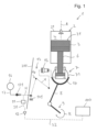
- 1 1 shows a first exemplary embodiment of a large diesel engine according to the invention, which is denoted overall by the reference symbol 1, in a highly schematic representation. In 1 only one cylinder 2 of the usually several cylinders 2 of the large diesel engine 1 is shown.
- a piston 3 is arranged in a manner known per se, which is arranged to be movable back and forth along a cylinder axis A between a lower reversal point and an upper reversal point.
- the piston 3 has an upper side 31 which, together with a cylinder cover 21, delimits a combustion chamber 4 in which the combustion process takes place.
- the piston 3 is connected via a piston rod 6 to a crosshead 7, which is connected via a connecting rod 8 to a crankshaft 9, so that the movement of the piston 3 via the piston rod 6, the crosshead 7 and the Push rod 8 is transmitted to the crankshaft 9 in order to rotate it.
- the rotation of the crankshaft is indicated by the arrow with the reference R.
- the crosshead 7 is designed in a manner known per se such that it converts the linear up and down movement of the piston 3 and the piston rod 6 into a rotational movement of the push rod 8, with the push rod 8 being pivotably mounted about a crosshead pin 71 of the crosshead 7.
- the structure and the individual components of the large diesel engine 1, such as the injection system for the liquid mode (not shown), the gas supply system for the gas mode (not shown), the gas exchange system, the exhaust system (not shown) or the turbocharger system (not shown) for the Provision of the scavenging or charging air for such a large diesel engine 1 is well known to the person skilled in the art both for the design as a two-stroke engine and for the design as a four-stroke engine and therefore does not require any further explanation here.
- the gas supply system for the gas mode usually comprises two gas inlet openings (not shown) through which the gas serving as fuel is introduced into the cylinder 2 in the gas mode.
- the two gas inlet openings are preferably arranged in the wall of the cylinder 2, particularly preferably in such a way that they are diametrically opposite one another and are arranged approximately in the middle between the upper and lower reversal point with respect to the axial direction defined by the cylinder axis A.
- an engine control system 100 is provided, with which the functions and the operation of the large diesel engine 1 are controlled.
- the engine control system 100 is an electronic system with which all engine or cylinder functions, in particular the injection (start and end of injection) both in gaseous mode and in liquid mode, and let the actuation of the exhaust valve 5 be adjusted or controlled.
- scavenging air slots are usually provided in the lower area of each cylinder 2 or cylinder liner, which are periodically closed and opened by the movement of the piston 3 in the cylinder 2, so that a turbocharger Scavenging air provided under a charge air pressure in an intake receiver (not shown) can flow through the scavenging air slots into the cylinder 2 as long as they are open.
- the mostly centrally arranged exhaust valve 5 is provided in the cylinder head or in the cylinder cover 21, through which the combustion gases can be discharged from the cylinder 2 into the exhaust system (not shown) after the combustion process.
- the exhaust system directs at least part of the combustion gases to a turbine (not shown) of the turbocharger, the compressor of which provides the charge air in the intake receiver at the charge air pressure.
- One or more fuel injection nozzles are provided for introducing the liquid fuel into the combustion chamber 4 of the cylinder 2 in the liquid mode, which are arranged, for example, in the cylinder cover 21 in the vicinity of the outlet valve 5 .
- the liquid mode for example, heavy oil or a diesel oil can be burned as the liquid fuel.
- a gas supply system known per se which comprises the gas inlet openings (not shown).
- the gas inlet openings are preferably each designed as a gas inlet valve with a gas inlet nozzle.
- the piston rod 6 is arranged in the crosshead pin 71 with its lower end according to the illustration. Furthermore, a hydraulic chamber 10 for setting a compression ratio is provided in the crosshead pin 71 .
- the compression ratio is a geometric variable which is the ratio of a first volume of combustion chamber 4 before compression of the scavenging air or the air-fuel mixture to a remaining second volume of combustion chamber 4 after compression of the scavenging air or air-fuel mixture.
- the first volume is the volume of the combustion chamber 4 immediately after the exhaust valve 5 closes, ie at the point in time when compression begins as the piston 3 moves upwards.
- the second volume is the volume of the combustion chamber 4 at maximum compression of the scavenging air or the air/fuel mixture. This is essentially the volume of the combustion chamber 4 at the start of the combustion process.
- the hydraulic chamber 10 for setting the compression ratio is designed in such a way that the piston rod 6 arranged in the crosshead pin 71 can be displaced as a whole relative to the crosshead pin 71 in the direction of the cylinder axis A.
- the piston rod 6 is designed and arranged in such a way that it delimits the hydraulic chamber 10 .
- the piston rod 6 can be displaced relative to the crosshead pin 71 by introducing a hydraulic medium, for example hydraulic oil, into the hydraulic chamber 10 or by draining the hydraulic medium from the hydraulic chamber 10 .
- a hydraulic medium for example hydraulic oil
- the compression ratio can thus be set steplessly between a minimum value and a maximum value.
- the large diesel engine 1 can be operated in gas mode with a lower compression ratio than in liquid mode.
- the compression ratio optimally as a function of other operating conditions or operating parameters, for example as a function of the temperature of the scavenging air (charge air), the methane number of the gas that is used as fuel in gas mode, or as a function of other operating parameters.
- a pressure sensor 11 is provided, with which a hydraulic pressure that prevails in the hydraulic chamber 10 can be determined, as well as an evaluation unit 12, with which a cylinder pressure prevailing in the combustion chamber 4 can be determined by means of the hydraulic pressure.
- the cylinder pressure prevailing in the combustion chamber is transmitted to the hydraulic medium in the hydraulic chamber 10 via the piston 3, whose upper side 31 delimits the combustion chamber 4, and the piston rod 6, and thus changes the hydraulic pressure prevailing in the hydraulic chamber 10.
- the cylinder pressure in the combustion chamber 4 can therefore be determined from the determination of the hydraulic pressure in the hydraulic chamber 10 .
- the pressure sensor 11 is provided at a measuring point which is arranged in a stationary manner with respect to a motor housing 200 .
- the motor housing 200 is indicated by the line 200.
- the engine housing 200 which for example includes the stand in which the slideways for the crossheads 7 are arranged, is stationary in the sense that it does not move during operation of the large diesel engine 1 relative to the space in which the large diesel engine 1 is arranged , apart from vibrations of course.
- the drive components ie in particular the piston 3, the piston rod 6, the crosshead 7, the connecting rod 8 and the crankshaft 9 are in motion relative to the engine housing 200 during operation of the large diesel engine 1, ie not stationary.
- stationary and non-stationary are to be understood in this sense: A stationary component does not move relative to the engine housing 200 during operation of the large diesel engine 1 .
- a non-stationary component moves relative to the engine housing 200 during operation of the large diesel engine 1.
- the piston 3 is a non-stationary component due to its stroke movement.
- a hydraulic pressure transmission device 13 is provided in order to transmit the hydraulic pressure that prevails in the hydraulic chamber 10 to the stationary pressure sensor 11 .
- the pressure transmission device 13 comprises a hydraulic line H, which is connected on the one hand to the hydraulic chamber 10 and on the other hand applies pressure to the pressure sensor 11 .
- the hydraulic line H is in 1 shown dashed.
- the hydraulic pressure transmission device 13 also includes a toggle lever 14 which is fastened in a manner known per se to the non-stationary crosshead 7 on the one hand and to a fixed point 141 which is arranged stationary with respect to the motor housing 200 on the other hand.
- the toggle lever 14, which is also referred to as a pivoting or rocking lever, can therefore follow the movement of the crosshead 7 with its one end, while its other end is attached to the fixed point 141 in a stationary manner relative to the motor housing 200.
- the hydraulic line H can be arranged on or in the toggle lever 14 .
- the hydraulic pressure transmission device 13 preferably includes a pressure reducer 15 in order to reduce the hydraulic pressure prevailing in the hydraulic chamber 10 to a lower pressure, with which the pressure sensor 11 is then acted upon.
- the pressure reducer 15 is preferably arranged and fixed on the crosshead 7 so that it moves together with the crosshead 7 .
- the pressure reducer 15 is arranged in the hydraulic line H in such a way that it is in fluid communication with the hydraulic chamber 10 on the high-pressure side and is subjected to the pressure prevailing in the hydraulic chamber 10 . On the low-pressure side, the pressure reducer 15 is connected to the pressure sensor 11, so that the pressure sensor 11 is subjected to the reduced pressure.
- the pressure reducer 15 has the advantage that not all of the hydraulic pressure acting in the hydraulic chamber 10 has to be transmitted from the crosshead 7 to the stationary measuring point at which the pressure sensor 11 is arranged, but only the reduced pressure. This pressure reduction by the pressure reducer 15 is taken into account in the evaluation unit 12 when determining the cylinder pressure.
- the pressure reducer 15 can, for example, comprise a pressure piston which has two pressure-loaded surfaces which are of different sizes, in order to thereby realize the pressure reduction.
- the pressure piston is then arranged in such a way that it moves in the horizontal direction, i.e. perpendicularly to the direction of movement of the crosshead 7 or the piston rod 6.
- the pressure sensor 11 is signal-connected to the evaluation unit 12 .
- This signal connection is implemented, for example, by a first signal line S1.
- the signal connections are in 1 shown with dotted lines.
- the evaluation unit 12 is signal-connected to the engine control system 100 .
- This signal connection is implemented, for example, by a second signal line S2.
- the cylinder pressure ascertained by the evaluation unit 12 is transmitted to the engine control system 100 via the second signal line S2 so that the latter knows the cylinder pressure in the combustion chamber 4 of the cylinder 2 .
- a calculation method is stored in the evaluation unit 12 , with which the evaluation unit 12 determines the cylinder pressure in the combustion chamber 4 of the cylinder 2 from the pressure or signal measured by the pressure sensor 11 .
- This calculation method takes into account the pressure reduction by the pressure reducer 15.
- the calculation method can also take into account other variables, for example dynamic forces such as centrifugal force or centrifugal force, which result from the movement of the piston 3 in order to calculate a measured value from the measured value transmitted by the pressure sensor 11 to ensure that the cylinder pressure is determined as accurately as possible.
- dynamic forces which result from the movement of the piston 3 and the piston rod 6, can depend, for example, on the speed at which the large diesel engine 1 is currently being operated.
- a first reservoir 16 for the hydraulic medium is provided in order to compensate for any leakage of hydraulic medium, for example leakage that can occur at the toggle lever 14 or at the pressure reducer 15 .
- the first reservoir 16 is connected to the hydraulic line H via a refill line 17, the refill line opening into the hydraulic line H at a point which is arranged between the fixed point 141 and the pressure sensor 11, i.e. the opening of the refill line 17 is in the stationary area of the hydraulic line H provided.
- a first check valve 171 is provided in the refill line 17 between its junction with the hydraulic line H and the first reservoir 16, which is arranged in such a way that the hydraulic medium can flow out of the first reservoir 16 into the hydraulic line H, but not out of the hydraulic line H in the first reservoir 16.
- the hydraulic medium introduced from the refill line 17 into the hydraulic line H can also be used to bring the pressure reducer 15 back into its starting position, for example by moving a pressure piston provided in the pressure reducer 15 to the right, as shown, i.e. towards the high-pressure side. is moved.
- a second throttle device 175 is provided in the refill line 17 between the first check valve 171 and the first reservoir 16 .
- the refilling of hydraulic medium from the first reservoir 16 into the hydraulic line H or the resetting of the pressure reducer 15 preferably takes place when the piston 3 is at the lower reversal point of its movement or in the vicinity of the lower reversal point of its movement.
- the pressure in the combustion chamber 4 acting on the upper side of the piston 31 is minimal, so that the hydraulic pressure in the hydraulic chamber 10 is also minimal.
- the pressure at which the hydraulic medium is present in the first reservoir 16 is so great that the hydraulic medium can flow through the refill line 17 into the hydraulic line H when the piston 3 is in the region of its lower reversal point.
- the pressure of the hydraulic medium in the first reservoir 16 is a few bars, e.g. B.
- This pressure is selected to be high enough so that the hydraulic medium can flow through the check valve 171 into the hydraulic line H when the piston 3 is in the area of its lower reversal point.
- the non-return valve 171 closes.
- the hydraulic pressure in the hydraulic chamber 10 increases and with it the pressure in the hydraulic line H.
- the hydraulic medium to be provided in the first reservoir 16 with a higher pressure of, for example, up to 100 bar, but pressures of less than 16 bar are preferred, because then the first reservoir 16 and its supply components are not to be regarded as a high-pressure system and can therefore be designed with a single wall.
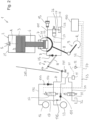
- FIG. 12 shows a schematic representation of a second exemplary embodiment of a large diesel engine 1 according to the invention.
- the second exemplary embodiment only the differences from the first exemplary embodiment will be discussed in more detail. Otherwise, the explanations of the first embodiment apply in the same way or in the same way for the second embodiment.
- parts that are the same or parts that are equivalent in function are denoted by the same reference numerals as in the first embodiment.
- the toggle lever 14 of the pressure transmission device 13 is also used for purposes other than for the hydraulic line H.
- the toggle lever 14 is therefore not designed as a separate toggle lever 14 that is used exclusively for the pressure transmission device 13, but rather as a Toggle lever 14 also serves other purposes.
- the toggle lever 14 is also used to introduce hydraulic medium into the hydraulic chamber 10 and to control the pressure relief in the hydraulic chamber 10.
- the toggle lever includes a supply Z, with which the hydraulic chamber 10 can be supplied with the hydraulic medium.
- the feed Z is designed, for example, as a line that is arranged in or on the toggle lever 14 .
- the feed Z is shown with a solid line in order to be able to better distinguish it from the hydraulic line H, which is used to measure the pressure.
- the feed Z is flow-connected on the one hand to the hydraulic chamber 10 and on the other hand can be connected via an actuating device 22 to a second reservoir 23 for the hydraulic medium.
- the hydraulic medium in the second reservoir 23 is at a significantly higher pressure than in the first reservoir 16, for example at ten times the pressure as in the first reservoir 16.
- the pressure in the second reservoir 23 is dimensioned such that the hydraulic chamber 10 is pressurized can be sufficient to lift the piston rod 6 and the piston 3 in the direction of the combustion chamber 4--as shown upwards--in order to adjust the compression ratio.
- the second reservoir 23 and the adjusting device 22 are arranged in a stationary manner with respect to the motor housing 200 .
- the adjusting device 22 serves to set the pressure in the feed Z in such a way that the desired compression ratio results.
- the actuating device 22 is designed, for example, as a proportional valve, which is signal-connected to the engine control system 100, for example via a third signal line S3, so that the engine control system 100 can control the actuating device 22. If the piston rod 6 and the piston 3 are to be raised in order to increase the compression ratio, the engine control system 100 controls the actuating device 22, for example the proportional valve, in such a way that such a pressure is set in the feed Z and thus in the hydraulic chamber 10 that the piston 3 is raised to the desired position.
- a second check valve 25 is also provided in the feed Z, which is arranged between the toggle lever 14 and the hydraulic chamber 10, ie in the non-stationary area of the feed Z.
- the second check valve 25 is preferably fixed to the crosshead 7.
- the second check valve 25 prevents the hydraulic medium from flowing back from the hydraulic chamber 10 into the feed Z.
- the adjusting device 22 is designed in such a way that it connects the feed Z to the second reservoir 23, in which the higher pressure prevails, or completely closes the flow connection between the feed Z and the second reservoir 23, as is shown in 2 is shown. This in 2 The state shown means that the adjusting device 22, which is preferably configured as a proportional valve, is completely closed.
- the feed Z is flow-connected to the second reservoir 23 via the actuating device 22 and the pressure is increased to the desired value via the proportional control.
- the open flow cross section of the proportional valve is increased or decreased, for example. If a lot of hydraulic medium is required to fill the hydraulic chamber 10, the flow cross section in the actuating device 22 is correspondingly increased, and as a result more hydraulic medium can enter the hydraulic chamber in that area of the working cycle in which the piston 3 is in the area of its lower reversal point 10 flow.
- the first reservoir 16 is also flow-connected to feed Z via a backup line 172 and a third check valve 174, with the third check valve 174 being arranged and designed in such a way that the hydraulic medium flows out of the first Reservoir 16 can flow into the supply Z, but not in the opposite direction from the supply Z into the first reservoir 16.
- a first throttle device 173 is provided in the backup line 172 between the third check valve 174 and the first reservoir 16.
- the backup line 172 serves to ensure that even when the actuating device 22 is fully closed, that is to say the feeder Z is decoupled from the second reservoir 23, the feeder Z cannot run empty, which could lead to undesirable dry running.
- the backup line 172 ensures that the feed Z is in flow connection at least with the first reservoir 16 and cannot empty itself completely , for example through leaks.
- the second check valve 25 prevents the hydraulic medium from flowing back from the hydraulic chamber 10 into the feed Z.
- the pressure reducer 15 in the hydraulic line H is flow-connected to the hydraulic chamber 10 on its high-pressure side.
- the pressure reducer 15 is flow-connected on the high-pressure side to an outlet line 101 which serves to discharge the hydraulic medium from the hydraulic chamber 10 .
- the outlet line 101 is flow-connected to a relief valve 26, which is used to discharge hydraulic medium from the hydraulic chamber 10.
- the relief valve 26 is designed here as a controllable two-way valve whose control port 27 is flow-connected via the hydraulic line H to the low-pressure side of the pressure reducer 15 .
- the relief valve 26 is thus controlled hydraulically.
- the pressure at the control connection 27 of the relief valve 26 is at least essentially the same as that prevailing on the low-pressure side of the pressure reducer 15 .
- the relief valve 26 If the relief valve 26 is in its in 2 shown open position, the flow connection between the outlet line 101 and an outlet 28 is open, and the hydraulic medium can flow out of the hydraulic chamber 10 through the outlet line 101 and the relief valve 26 to the outlet 28, through which the hydraulic medium flows into a container 29, for example a tank or tub. If the relief valve 26 is in its closed position, it closes the flow connection between the outlet line 101 and the outlet 28, so that the hydraulic medium cannot flow out of the hydraulic chamber 10 into the container 29.
- the outlet line 101 in which the same pressure prevails as in the hydraulic chamber 10, is thus connected to the hydraulic line H via two parallel branches for pressure exchange, namely on the one hand via the pressure reducer 15, the high-pressure side of which is connected to the outlet line 101, and its The low-pressure side is connected to the hydraulic line H, and on the other hand via the relief valve 26, whose control port 27 is connected to the hydraulic line H.
- the hydraulic line H also serves as a control line for the relief valve 26 for draining hydraulic medium from the hydraulic chamber 10.
- the hydraulic line H is connected on its stationary side via the refill line 17 to the first reservoir 16, with the refill line 17 opening into the hydraulic line H at a point that is arranged between the fixed point 141 and the pressure sensor 11.
- the first check valve 171 is provided in the refill line 17 and is arranged in such a way that the hydraulic medium can flow from the first reservoir 16 into the hydraulic line H, but not from the hydraulic line H into the first reservoir 16.
- the hydraulic line H is flow-connected in its stationary area to a relief line 30 in which a controllable switching element 31 is provided, which is designed here as a shut-off element that selectively opens or closes the passage through the relief line 30 .
- the switching element 31 is designed, for example, as a controllable shut-off valve, for example as a two-way valve.
- the switching element 31 is signal-connected to the engine control system 100, for example via a fourth signal line S4, so that the engine control system 100 can control the switching element 31.
- the relief line 30 opens into a further container 32, for example a tank or a trough, which can be the same as the container 29.
- the pressure in the hydraulic line H is reduced by the pressure reducer 15, which is proportional to the hydraulic pressure in the hydraulic chamber 10, so that the cylinder pressure, which prevails in the combustion chamber 4 can be determined. Further, the discharge line 101 is kept closed with the relief valve 26.
- engine control system 100 controls switching element 31 via fourth signal line S4 in such a way that it opens the passage through relief line 30 .
- the pressure in the hydraulic line H is relieved, as a result of which, in particular, the pressure at the control connection 27 of the relief valve 26 also drops.
- the relief valve 26 opens and the hydraulic medium can flow out of the hydraulic chamber 10 via the outlet line 101 and the outlet 28 .
- the second throttle device 175 in the refill line 17 prevents sufficient hydraulic medium from being able to flow from the first reservoir 16 so that the pressure in the hydraulic line H drops as desired and the relief valve 26 switches to the open position.
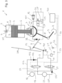
- FIG. 12 shows a schematic representation of a third exemplary embodiment of a large diesel engine 1 according to the invention.
- the third exemplary embodiment only the differences from the first and second exemplary embodiments will be discussed in more detail. Otherwise, the explanations of the first and the second embodiment apply in the same way or in the same way for the third embodiment.
- parts that are the same or parts that are equivalent in function are denoted by the same reference numerals as in the first and second embodiments.
- the hydraulic connection which serves to relieve the hydraulic chamber 10 is used as a hydraulic line H for the pressure measurement, i.e. the toggle lever 14 of the pressure transmission device 13 is also used to control the pressure relief of the hydraulic Chamber 10 used.
- the hydraulic line H which also serves as a control line for the relief valve 26, can be connected either to the first reservoir 16 or to the second reservoir 23.
- the switching element 31 in the third exemplary embodiment is designed as a switchover valve, for example as a 3/2-way valve, which is connected at its output to the relief line 30, which is flow-connected to the hydraulic line H.
- the two inputs of the switching element 31 one is flow-connected via the refill line 17 to the first reservoir 16, in which the lower pressure prevails, and the other input is flow-connected via a supply line 231 to the second reservoir 23, in which the higher pressure prevails .
- a fourth check valve 232 is also provided in supply line 231, which is arranged and designed in such a way that it allows the hydraulic medium to flow from the second reservoir 23 into the switching element 31, but allows the hydraulic medium to flow back through the supply line 231 into the second reservoir 23 prevented.
- the hydraulic line H is flow-connected to the first reservoir 16 via the relief line 30 and the refill line 17 . If the switching element 31 is in its other switching position, the hydraulic line H is flow-connected to the second reservoir 23 via the relief line 30 and the supply line 231 .
- the switching position of the switching element 31 shown is preferably only used when the VCR system is deactivated. If the hydraulic line H is flow-connected to the first reservoir 16 , then only the lower pressure that prevails in the first reservoir 16 is also present at the control connection 27 of the relief valve 26 . Depending on how high the lower pressure in the first reservoir 16 is selected, it is possible that the lower pressure in the first reservoir 16 is not sufficient to keep the relief valve 26 in the closed position. Therefore, the in 3 Switching position shown of the switching element 31 is preferably only selected when the VCR system is deactivated.
- the switching element 31 When the VCR system is active or activated, the switching element 31 is brought into the switching position in which the hydraulic line H is flow-connected via the relief line 30 and the supply line 231 to the second reservoir 23, in which the higher pressure prevails. Since the higher pressure is now present at the control connection 27 of the relief valve 26, this is reliably brought into its closed position and held there. Since the fourth check valve 231 also prevents the hydraulic medium from flowing back when the pressure in the hydraulic line H is greater is than the pressure in the second reservoir 23, the cylinder pressure can now be determined via the hydraulic line H with the aid of the pressure sensor 11 and the evaluation unit 12.
- the third exemplary embodiment has the particular advantage that even when the VCR system is deactivated, the toggle lever 14 or the hydraulic line H remains filled with hydraulic medium and cannot run empty because the hydraulic line H is flow-connected to the first reservoir 16 even when the VCR system is deactivated.
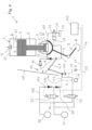
- FIG. 12 shows a schematic representation of a fourth exemplary embodiment of a large diesel engine 1 according to the invention.
- the fourth exemplary embodiment only the differences from the first, second and third exemplary embodiments will be discussed in more detail. Otherwise, the explanations of the first, the second and the third embodiment apply in the same way or in the same way for the fourth embodiment.
- parts that are the same or parts that are equivalent in function are denoted by the same reference numerals as in the first, second, and third embodiments.
- the pressure is measured via the feed Z, with which the hydraulic medium can be fed to the hydraulic chamber 10 .
- the feed Z is used as a hydraulic line H for the pressure measurement. Since the hydraulic line H for the pressure measurement is shown in dashed lines, in the fourth exemplary embodiment in FIG 4 the feeder Z is also shown in dashed lines.
- the control line for controlling the relief valve 26 is in 4 shown with a solid line and denoted by the reference character L.
- the pressure reducer 15 is flow-connected to the feed Z on the low-pressure side.
- the pressure reducer 15 is connected to the feed Z at a point which is arranged between the toggle lever 14 and the second check valve 25 as viewed in the direction of flow.
- the pressure reducer 15 is flow-connected to the hydraulic chamber 10 , so that the pressure prevailing in the hydraulic chamber 10 is applied to the high-pressure side of the pressure reducer 15 .
- the pressure reducer 15 is arranged in parallel with the second check valve 25 .
- the feed Z is used as a hydraulic line H for pressure measurement.
- a branch 142 is provided in the stationary region of the feed Z, at which the hydraulic line H branches off from the feed Z and extends to the pressure sensor 11 .
- the feed Z extends from this branch 142 to the control device 22.
- the adjusting device 22 is designed in such a way that it optionally connects the feed Z either to the second reservoir 23, in which the higher pressure prevails, or the flow connection between the feed Z and the second reservoir 23 is completely closed, as is also the case in 4 is shown. This in 4 The state shown means that the adjusting device 22, which is preferably configured as a proportional valve, is completely closed.
- a fifth check valve 221 is provided in the flow connection between the branch 142 and the actuating device 22, which is arranged and configured in such a way that it allows the hydraulic medium to flow from the actuating device 22 to the branch 142 , but prevents the hydraulic medium from flowing back from the branch 142 in the direction of the actuating device 22 .
- control line L for activating the relief valve 26 can be flow-connected by means of the switching element 31 either to the first reservoir 16 (lower pressure) or to the second reservoir 23 (higher pressure).
- the filling or refilling of the hydraulic chamber 10 with hydraulic medium also takes place here when the piston 3 is in the region of its lower reversal point, because here, viewed over the working cycle, the pressure in the hydraulic chamber 10 is lowest.
- the fifth check valve 221 and the second check valve 25 open, so that the hydraulic medium flows into the hydraulic chamber 10 in a manner known per se, for example to compensate for leakage losses.
- the pressure reducer 15 is brought to its initial position by the hydraulic medium, for example by displacing a pressure piston of the pressure reducer 15.
- the pressure in the hydraulic chamber 10 increases, causing the second check valve 25 closes.
- the fifth check valve 221 also closes.
- the pressure reducer 15 increases the pressure in the hydraulic line H proportionally to the hydraulic pressure in the hydraulic chamber 10, and thus proportionally to the cylinder pressure.
- the pressure prevailing in the hydraulic line H is detected on the stationary side of the hydraulic line H by the pressure sensor 11 and sent to the Evaluation unit 12 for determining the cylinder pressure in the combustion chamber 4 of the cylinder 2 forwarded.
- FIG. 12 shows a schematic representation of a fifth exemplary embodiment of a large diesel engine 1 according to the invention.
- the fifth exemplary embodiment only the differences from the exemplary embodiments described above will be discussed in more detail. Otherwise, the explanations of the exemplary embodiments described above also apply in the same way or in the same way to the fifth exemplary embodiment.
- parts that are the same or parts that are equivalent in function are denoted by the same reference symbols as in the exemplary embodiments described above.
- the pressure sensor 11 is arranged on the crosshead 7 such that the pressure sensor 11 moves together with the crosshead 7 .
- the pressure sensor 11 is therefore not stationary in the fifth exemplary embodiment, but moves relative to the motor housing.
- the measured values determined by the pressure sensor 11 are then transmitted to the evaluation unit 12 which is typically—but not necessarily—stationary.
- This transmission from the pressure sensor 11 to the evaluation unit 12 can take place, for example, via a wireless signal connection, e.g. with a transmitter on the pressure sensor 11 and a receiver on the evaluation unit 12. It is also possible to carry out the transmission using the first signal line S1, which is a flexible cable is configured and connects the evaluation unit 12 to the pressure sensor 11 that can be moved relative to it.
- Such a cable can be arranged, for example, on or in a toggle lever.
- this can also be one of the toggle levers in the large diesel engine 1, which are arranged between the stationary engine housing 200 and the crosshead 7 that moves in the operating state, for example in order to introduce lubricating or cooling media into the crosshead 7 or into the piston rod 6.
- the toggle lever with which the hydraulic medium for displacing the piston rod 6 is supplied to the hydraulic chamber 10 can also be used for guiding the first signal line S1.
- a pressure reducer 15 can also be provided in the hydraulic line H between the hydraulic chamber 10 and the pressure sensor 11 in the fifth exemplary embodiment.
Landscapes
- Engineering & Computer Science (AREA)
- Mechanical Engineering (AREA)
- General Engineering & Computer Science (AREA)
- Chemical & Material Sciences (AREA)
- Combustion & Propulsion (AREA)
- Output Control And Ontrol Of Special Type Engine (AREA)
- Testing Of Engines (AREA)
- Measuring Fluid Pressure (AREA)
Priority Applications (4)
| Application Number | Priority Date | Filing Date | Title |
|---|---|---|---|
| EP21212548.8A EP4191046A1 (fr) | 2021-12-06 | 2021-12-06 | Gros moteur diesel et procédé de détermination de la pression de cylindre dans un gros moteur diesel |
| JP2022178806A JP2023084098A (ja) | 2021-12-06 | 2022-11-08 | 大型ディーゼル・エンジン、及び大型ディーゼル・エンジンにおいてシリンダ圧を決定する方法 |
| CN202211398730.2A CN116220897A (zh) | 2021-12-06 | 2022-11-09 | 大型柴油发动机和确定大型柴油发动机的气缸压力的方法 |
| KR1020220157183A KR20230085079A (ko) | 2021-12-06 | 2022-11-22 | 대형 디젤 엔진 및 대형 디젤 엔진에서 실린더 압력을 결정하기 위한 방법 |
Applications Claiming Priority (1)
| Application Number | Priority Date | Filing Date | Title |
|---|---|---|---|
| EP21212548.8A EP4191046A1 (fr) | 2021-12-06 | 2021-12-06 | Gros moteur diesel et procédé de détermination de la pression de cylindre dans un gros moteur diesel |
Publications (1)
| Publication Number | Publication Date |
|---|---|
| EP4191046A1 true EP4191046A1 (fr) | 2023-06-07 |
Family
ID=79024512
Family Applications (1)
| Application Number | Title | Priority Date | Filing Date |
|---|---|---|---|
| EP21212548.8A Withdrawn EP4191046A1 (fr) | 2021-12-06 | 2021-12-06 | Gros moteur diesel et procédé de détermination de la pression de cylindre dans un gros moteur diesel |
Country Status (4)
| Country | Link |
|---|---|
| EP (1) | EP4191046A1 (fr) |
| JP (1) | JP2023084098A (fr) |
| KR (1) | KR20230085079A (fr) |
| CN (1) | CN116220897A (fr) |
Citations (4)
| Publication number | Priority date | Publication date | Assignee | Title |
|---|---|---|---|---|
| EP0643291A1 (fr) * | 1993-09-09 | 1995-03-15 | New Sulzer Diesel AG | Dispositif pour déterminer la pression dans un cylindre d'un moteur à piston, et moteur diesel équipé d'un tel dispositif |
| EP2687707A2 (fr) | 2012-07-17 | 2014-01-22 | Wärtsilä Schweiz AG | Moteur à combustion à piston alternatif important, appareil de commande et procédé de commande d'un tel moteur |
| US20200291874A1 (en) * | 2018-03-16 | 2020-09-17 | Ihi Corporation | Engine |
| US20200392929A1 (en) * | 2018-03-16 | 2020-12-17 | Ihi Corporation | Engine |
-
2021
- 2021-12-06 EP EP21212548.8A patent/EP4191046A1/fr not_active Withdrawn
-
2022
- 2022-11-08 JP JP2022178806A patent/JP2023084098A/ja active Pending
- 2022-11-09 CN CN202211398730.2A patent/CN116220897A/zh active Pending
- 2022-11-22 KR KR1020220157183A patent/KR20230085079A/ko unknown
Patent Citations (4)
| Publication number | Priority date | Publication date | Assignee | Title |
|---|---|---|---|---|
| EP0643291A1 (fr) * | 1993-09-09 | 1995-03-15 | New Sulzer Diesel AG | Dispositif pour déterminer la pression dans un cylindre d'un moteur à piston, et moteur diesel équipé d'un tel dispositif |
| EP2687707A2 (fr) | 2012-07-17 | 2014-01-22 | Wärtsilä Schweiz AG | Moteur à combustion à piston alternatif important, appareil de commande et procédé de commande d'un tel moteur |
| US20200291874A1 (en) * | 2018-03-16 | 2020-09-17 | Ihi Corporation | Engine |
| US20200392929A1 (en) * | 2018-03-16 | 2020-12-17 | Ihi Corporation | Engine |
Also Published As
| Publication number | Publication date |
|---|---|
| CN116220897A (zh) | 2023-06-06 |
| KR20230085079A (ko) | 2023-06-13 |
| JP2023084098A (ja) | 2023-06-16 |
Similar Documents
| Publication | Publication Date | Title |
|---|---|---|
| EP2992195B1 (fr) | Moteur à combustion interne à piston alternatif ainsi que procédé pour faire fonctionner un moteur à combustion interne à piston alternatif | |
| EP3574204B1 (fr) | Moteur à combustion interne comprenant un injecteur de carburant doté d'une alimentation supplémentaire de la chambre de combustion en fluide favorisant la combustion | |
| EP3872330A1 (fr) | Procédé de fonctionnement d'un grand moteur diesel, ainsi que grand moteur diesel | |
| EP3786498A1 (fr) | Vanne d'arrêt pour une conduite à double paroi, système d'alimentation en gaz et gros moteur | |
| EP3951160B1 (fr) | Soupape d'injection de carburant et procédé d'injection de carburant pour un gros moteur diesel, ainsi que gros moteur diesel | |
| EP3015679B1 (fr) | Cylindre pour un moteur a combustion interne a piston elevateur, moteur a combustion interne a piston elevateur, ainsi que procede de fonctionnement d'un moteur a combustion interne a piston elevateur | |
| DE102017120512B4 (de) | Verfahren zum Betreiben eines Wasserstoffmotors für ein Kraftfahrzeug | |
| DE69728270T2 (de) | Brennstoff-gas-gemisch einspritzsystem | |
| EP3095993A1 (fr) | Procede de fonctionnement d'un gros moteur diesel, utilisation d'un tel procede et gros moteur diesel | |
| WO2014060071A1 (fr) | Procédé permettant de faire fonctionner un moteur alternatif à combustion interne | |
| EP3121428B1 (fr) | Procede de fonctionnement d'un gros moteur diesel, utilisation d'un tel procede et gros moteur diesel | |
| EP2677141A1 (fr) | Procédé de fonctionnement dýun grand moteur diesel deux temps, ainsi que grand moteur diesel deux temps | |
| EP3404235A1 (fr) | Gros moteur diesel et procédé de fonctionnement d'un gros moteur diesel | |
| EP3483420B1 (fr) | Buse d'injection de carburant et procédé d'injection de carburant pour un gros moteur diesel ainsi que gros moteur diesel | |
| EP4191046A1 (fr) | Gros moteur diesel et procédé de détermination de la pression de cylindre dans un gros moteur diesel | |
| CH705513A2 (de) | Zylinderanordnung für eine längsgespülte Hubkolbenbrennkraftmaschine. | |
| WO2018069206A1 (fr) | Procédé et dispositif pour commander une pompe à liquide de refroidissement | |
| DE2713831A1 (de) | Arbeitsverfahren fuer verbrennungskraftmaschinen mit zusatz von wasserdampf und verbrennungskraftmaschine fuer die durchfuehrung des verfahrens | |
| EP2682572B1 (fr) | Système de lubrification | |
| EP4019751A1 (fr) | Procédé de fonctionnement d'un grand moteur diesel, ainsi que grand moteur diesel | |
| EP3564642A1 (fr) | Dispositif de determination de la pression dans un moteur a combustion d'un grand moteur et de grand moteur | |
| EP4166766A1 (fr) | Grand moteur diesel à balayage axial | |
| DE19706959A1 (de) | Zündverfahren für einen Hubkolben-Gasmotor | |
| DE843922C (de) | Verbrennungsverfahren zum Betriebe einer hochgeladenen Brennkraftmaschine | |
| EP3726036A1 (fr) | Procédé de fonctionnement d'un grand moteur ainsi que grand moteur |
Legal Events
| Date | Code | Title | Description |
|---|---|---|---|
| PUAI | Public reference made under article 153(3) epc to a published international application that has entered the european phase |
Free format text: ORIGINAL CODE: 0009012 |
|
| STAA | Information on the status of an ep patent application or granted ep patent |
Free format text: STATUS: THE APPLICATION HAS BEEN PUBLISHED |
|
| AK | Designated contracting states |
Kind code of ref document: A1 Designated state(s): AL AT BE BG CH CY CZ DE DK EE ES FI FR GB GR HR HU IE IS IT LI LT LU LV MC MK MT NL NO PL PT RO RS SE SI SK SM TR |
|
| STAA | Information on the status of an ep patent application or granted ep patent |
Free format text: STATUS: THE APPLICATION IS DEEMED TO BE WITHDRAWN |
|
| 18D | Application deemed to be withdrawn |
Effective date: 20231208 |