EP4190502A1 - Gefederte kontakte in einem teilgehäuse für einen akkumulator - Google Patents
Gefederte kontakte in einem teilgehäuse für einen akkumulator Download PDFInfo
- Publication number
- EP4190502A1 EP4190502A1 EP21211593.5A EP21211593A EP4190502A1 EP 4190502 A1 EP4190502 A1 EP 4190502A1 EP 21211593 A EP21211593 A EP 21211593A EP 4190502 A1 EP4190502 A1 EP 4190502A1
- Authority
- EP
- European Patent Office
- Prior art keywords
- chamber
- connection
- accumulator
- machine tool
- connection element
- Prior art date
- Legal status (The legal status is an assumption and is not a legal conclusion. Google has not performed a legal analysis and makes no representation as to the accuracy of the status listed.)
- Pending
Links
- 238000004146 energy storage Methods 0.000 claims abstract description 16
- 210000000352 storage cell Anatomy 0.000 claims abstract description 16
- 230000035939 shock Effects 0.000 description 6
- 230000004913 activation Effects 0.000 description 4
- 210000004027 cell Anatomy 0.000 description 4
- 230000006835 compression Effects 0.000 description 4
- 238000007906 compression Methods 0.000 description 4
- 230000001105 regulatory effect Effects 0.000 description 3
- 239000000463 material Substances 0.000 description 2
- 230000003213 activating effect Effects 0.000 description 1
- 230000000712 assembly Effects 0.000 description 1
- 238000000429 assembly Methods 0.000 description 1
- 230000005540 biological transmission Effects 0.000 description 1
- 230000000903 blocking effect Effects 0.000 description 1
- 230000001419 dependent effect Effects 0.000 description 1
- 229920001971 elastomer Polymers 0.000 description 1
- 239000000806 elastomer Substances 0.000 description 1
- 230000002028 premature Effects 0.000 description 1
Images


Classifications
-
- B—PERFORMING OPERATIONS; TRANSPORTING
- B25—HAND TOOLS; PORTABLE POWER-DRIVEN TOOLS; MANIPULATORS
- B25F—COMBINATION OR MULTI-PURPOSE TOOLS NOT OTHERWISE PROVIDED FOR; DETAILS OR COMPONENTS OF PORTABLE POWER-DRIVEN TOOLS NOT PARTICULARLY RELATED TO THE OPERATIONS PERFORMED AND NOT OTHERWISE PROVIDED FOR
- B25F5/00—Details or components of portable power-driven tools not particularly related to the operations performed and not otherwise provided for
- B25F5/02—Construction of casings, bodies or handles
-
- B—PERFORMING OPERATIONS; TRANSPORTING
- B25—HAND TOOLS; PORTABLE POWER-DRIVEN TOOLS; MANIPULATORS
- B25F—COMBINATION OR MULTI-PURPOSE TOOLS NOT OTHERWISE PROVIDED FOR; DETAILS OR COMPONENTS OF PORTABLE POWER-DRIVEN TOOLS NOT PARTICULARLY RELATED TO THE OPERATIONS PERFORMED AND NOT OTHERWISE PROVIDED FOR
- B25F1/00—Combination or multi-purpose hand tools
-
- B—PERFORMING OPERATIONS; TRANSPORTING
- B25—HAND TOOLS; PORTABLE POWER-DRIVEN TOOLS; MANIPULATORS
- B25F—COMBINATION OR MULTI-PURPOSE TOOLS NOT OTHERWISE PROVIDED FOR; DETAILS OR COMPONENTS OF PORTABLE POWER-DRIVEN TOOLS NOT PARTICULARLY RELATED TO THE OPERATIONS PERFORMED AND NOT OTHERWISE PROVIDED FOR
- B25F5/00—Details or components of portable power-driven tools not particularly related to the operations performed and not otherwise provided for
Definitions
- the present invention relates to an accumulator, preferably as a detachable energy supply for a machine tool, containing at least one energy storage cell and a connection device for detachably connecting the accumulator to a machine tool, the connection device containing at least a first, second and third connection element.
- So-called cordless machine tools such as cordless screwdrivers, drills, saws, grinders or the like, can be connected to one or more accumulators for the energy supply.
- the accumulator has a large number of energy storage cells, also called accumulator cells, with the help of which electrical energy can be absorbed, stored and released again. If the accumulator is connected to a machine tool, the electrical energy stored in the energy storage cells can be supplied to the consumers (e.g. a brushless electric motor) of the machine tool.
- the accumulator For charging, i.e. filling the energy storage cells with electrical energy, the accumulator is connected to a charging device so that electrical energy can reach the energy storage cells.
- the interface between the machine tool and the battery represents a particular problem.
- the electrical contacts of the machine tool and the electrical contacts of the battery are connected to one another in such a way that the electrical energy stored in the energy storage cells can travel from the battery to the machine tool.
- the accumulator is only detachable is in contact with the machine tool through the interface, the respective electrical contacts of the machine tool and of the accumulator are in force-locked contact with one another.
- Such non-positive connections usually consist of a spring-loaded clip (ie female contact) and an insertable element (ie male contact) which can be inserted into the clip.
- the vibrations and shocks on the machine tool and on the accumulator connected to the machine tool can lead to a relative movement and even to an actual interruption of the contact connection.
- the relative movement is to be avoided, as this can lead to wear or premature wear of the contacts.
- a break in the contact connection can lead to unwanted sparking or even an arc at the contacts.
- a vibration or shock-proof connection of the respective electrical contacts is therefore to provide a battery interface for a battery, preferably as a detachable energy supply for a machine tool, with a connection device which has at least a first, second and third connection element. with which the above-mentioned problem can be solved and a vibration-proof or shock-proof connection can be achieved.
- an accumulator preferably as a detachable energy supply for a machine tool, containing at least one energy storage cell and a connection device for detachably connecting the accumulator to a machine tool, the connection device containing at least a first, second and third connection element.
- the connecting device contains a holding and receiving device for at least partially receiving the first, second and third connecting element, each connecting element being connected to the holding and receiving device by at least one compensating element in such a way that a relative movement in at least one direction between the connecting element and the holding and receiving device can be compensated.
- connection elements can be compensated for in a simple manner, which lead to a relative movement and even to a actual interruption of the contact connection between the accumulator and the machine tool.
- the holding and receiving device contains at least a first, second and third essentially elongated chamber, in each of which a connecting element with an associated compensation element can be positioned, so that the connecting element can be positioned with the aid of the associated Compensating element is reversibly movable in one direction relative to the respective chamber.
- a chamber can accommodate more than a single connecting element.
- a first chamber can contain two or more than two connection elements designed as positive poles.
- a second chamber can also contain two or more than two connection elements designed as negative poles, and
- a third chamber can contain two or more than two connection elements designed as a communication element.
- each chamber it may be possible for each chamber to be designed in the form of a frame without continuous or closed side walls.
- the compensating element can be designed in the form of a spring and in particular a spiral spring.
- the compensating element can be designed as a component with an elastically deformable material.
- An elastomer is also possible as the material. In this way, a vibration-induced movement of the connection element in several directions, i.e. not only in the direction towards or against the connection element, can be counteracted in a simple manner.
- At least two chambers are offset from one another in at least one plane on the holding and receiving device.
- a mechanical resistance can be reduced, which can arise if too many connection elements lying on one plane are to be brought into contact with corresponding contact elements of a machine tool or a charging device at the same time.
- the staggered arrangement allows a first number of connection elements of the accumulator to be brought into a contact connection with corresponding connection elements of a machine tool or a charging device and then a second number of connection elements of the accumulator to be brought into a contact connection with corresponding connection elements of a machine tool or a charging device.
- the first chamber is connected to the second chamber by a first elastic connecting element and the second chamber is connected to the third chamber by a second elastic connecting element.
- the first chamber is connected to the second chamber by a first rigid connecting element and the second chamber is connected to the third chamber by a second rigid connecting element.
- first rigid connecting element is connected to the second chamber by a first rigid connecting element and the second chamber is connected to the third chamber by a second rigid connecting element.
- the connecting elements of the machine tool or a charger are designed in the form of pin-like plugs and the connecting elements of the battery interface are designed in the form of clamps with elastically deformable plates for accommodating pin-like plugs.
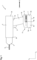
- the machine tool 1 is designed in the form of a drill. However, it is also possible for the machine tool 1 to be a hammer drill, a circular saw, a grinder or the like.
- the machine tool 1 shown essentially contains a housing 2, a tool holder 3, a handle 4 with an activation switch 5.
- the machine tool 1 also contains an interface device 6 for a battery 7.
- FIG 1 a state is shown in which the accumulator 7 is connected to the machine tool 1 .
- the accumulator 7 is pushed onto the interface device 6 in the direction of the arrow A.
- the accumulator 7 can be removed again from the interface device 6 and thus from the machine tool 1 in accordance with the direction of the arrow B. If the accumulator 7 is connected to the machine tool 1 , electrical energy can reach the machine tool 1 from the accumulator 7 .
- the housing 2 of the machine tool 1 has a first end 2a and a second end 2b.
- the tool holder 3 is positioned at a first end 2a of the housing 2 .
- the tool holder 3 is used to record and releasably hold a tool 8.
- the in the figures 1 and 2 Tool 8 shown is designed in the form of a drill.
- An electric motor for generating a torque is positioned inside the housing 2 .
- the electric motor is therefore an electrical consumer of electrical energy.
- the torque generated in the electric motor is transmitted to the tool holder 3 via an output shaft and a gear.
- the tool 8 is rotated with the aid of the transmitted torque.
- the handle 4 includes the activation switch 5, a first end 4a and a second end 4b.
- the activation switch 5 is used for actuating or activating the machine tool 1 by a user. The user is not shown in the figures.
- the first end 4a of the handle 4 is attached.
- the interface device 6 for a releasable connection of the accumulator 7 is positioned.
- the interface device 6 contains a first, second and third connection element 6a, 6b, 6c.
- the interface device 6 can also contain more or less than a first, second and third connection element.
- the first connection element 6a is designed as a positive pole, the second connection element 6b as a negative pole and the third connection element 6c as a communication element.
- the first connecting element 6a as a positive pole and the second connecting element 6b as a negative pole
- an electrical circuit can be generated or closed between the machine tool 1 and the accumulator 7 for supplying the machine tool 1 with electrical energy.
- Information in the form of data and signals can be received and sent from the machine tool 1 with the aid of the third connection element 6c designed as a communication element, so that communication between the machine tool 1 and the accumulator 7 can take place.
- the third connection element 6c designed as a communication element is positioned on the interface device 6 between the first connection element 6a designed as a positive pole and the second connection element 6b designed as a negative pole and is thus arranged essentially in the middle of the interface device 6.
- the three or more connecting elements are also possible.
- the battery 7 shown essentially contains a battery housing 9.
- the battery housing 9 in turn contains a front 9a, a rear 9b, a left side wall 9c, a right side wall, a top 9e and a bottom 9f.
- a front 9a a front 9a
- a rear 9b a left side wall 9c
- a right side wall a top 9e and a bottom 9f.
- the left side wall 9c of the battery case 9 is shown, but the left and right side walls are essentially identical.
- connection device 10 is positioned on the upper side 9e of the rechargeable battery housing 9 .
- the connection device 10 can also be referred to as a battery interface device.
- the respective energy storage cells 11 are connected to the connection device 10 .
- electrical energy can be received in the accumulator 7, stored and released again.
- connection of the battery cells 11 among themselves nor the connection of the battery cells 11 to the connection device 10 are not shown in the figures.
- the accumulator 7 contains a control device 12, with the aid of which the functions of the accumulator 7 are controlled and regulated.
- the functions of the accumulator 7, which can be controlled or regulated by the control device 12, include, for example, regulating the amount of electrical energy or blocking the delivery of electrical energy from the energy storage cells 11.
- the control device 12 of the accumulator 7 is connected to the Energy storage cells 11 connected. The connections of the control device 12 to the individual energy storage cells 11 are not shown in the figures.
- the connecting device 10 essentially contains a holding and receiving device 13 for receiving and holding a first, second and third connecting element 13a, 13b, 13c.
- the first, second and third connection element 13a, 13b, 13c is connected to the control device 12 in each case.
- the first connection element 13a is designed as a positive pole, the second connection element 13b as a negative pole and the third connection element 13c as a communication element.
- more than three connection elements can be provided, so that for example a first and second positive pole, a first and second negative pole and a first and second communication element are contained in the holding and receiving device 13 .
- the first connection element 13a of the accumulator 7 designed as a positive pole serves for the releasable connection to the corresponding first connection element 6a of the machine tool 1 designed as a positive pole second connection element 6b of the machine tool 1.
- the third connection element 13c, designed as a communication element, of the accumulator 7 is used for the releasable connection to the corresponding third connection element 6c, designed as a communication element, of the machine tool 1.
- the first, second and third connection elements 13a, 13b, 13c of the accumulator 7 each contain a terminal 14a, 14b, 14c.
- the clamp can also be referred to as a clamp.
- the first, second and third connecting element 6a, 6b, 6c of the machine tool 1 each contain a sword 15a, 15b, 15c as a contact.
- the sword 15a, 15b, 15c can also be designed as an elongated contact pin, so that each connecting element 6a, 6b, 6c of the machine tool 1 can be accommodated in the corresponding connecting element 13a, 13b, 13c of the accumulator 7.
- the connection element 6a, 6b, 6c is held in place or brought into contact by a certain spring force of the connection elements 13a, 13b, 13c.
- connection device 13 contains a first, second and third chamber 16a, 16b, 16c.
- Each chamber 16a, 16b, 16c serves to accommodate at least one connecting element 13a, 13b, 13c.
- the chamber 16a, 16b, 16c can also be referred to as a shaft.
- each chamber may be designed in the form of a frame without continuous or closed side walls.
- Each chamber 16a, 16b, 16c has a first end 17a and a second end 17b.
- a first opening 18a is provided at the first end 17a of each chamber 16a, 16b, 16c and a second opening 18b is provided at the second end 17b of each chamber 16a, 16b, 16c.
- the opening can also be referred to as a recess.
- the first connection element 13a is in the first chamber 16a
- the second connection element 13b is in the second chamber 16b
- the third connection element 13c is positioned in the third chamber 16c.
- a chamber may accommodate more than one connection element.
- a first chamber 16a can contain two or more than two connection elements configured as positive poles.
- a second chamber 16b can also contain two or more than two connection elements designed as negative poles, and
- a third chamber 16c can contain two or more than two connection elements designed as a communication element.
- each chamber 16a, 16b, 16c is essentially elongate and is dimensioned a certain distance longer than the corresponding connecting element 13a, 13b, 13c positioned in the respective chamber 16a, 16b, 16c.
- the chamber 16a, 16b, 16c is made longer so that the connecting element 13a, 13b, 13c can move in the direction of the arrow A or B in the chamber 16a, 16b, 16c.
- connection element 13a, 13b, 13c protrudes from the respective chamber through the first opening 18a at the first end 17a of each chamber 16a, 16b, 16c 16a, 16b, 16c that the two legs of each clamp 14a, 14b, 14c are freely movable outside the chamber 16a, 16b, 16c for receiving a sword 15a, 15b, 15c of a connecting element 6a, 6b, 6c of the machine tool, cf . figure 5 .
- each connection element 13a, 13b, 13c contains a respective compensating element 19a, 19b, 19c.
- each compensating element 19a, 19b, 19c is designed in the form of a spiral spring and in particular as a compression spring.
- Each spring has a first and second end 20,21.
- the first end 20 of a spring-designed compensating element 19a, 19b, 19c is connected to the respective rear end of a connecting element 13a, 13b, 13c.
- the second end 21 of a spring-designed compensating element 19a, 19b, 19c is connected to the respective second end 17b of a chamber 16a, 16b, 16c.
- the connecting element 13a, 13b, 13c Due to the special design of the compensating element 19a, 19b, 19c as a compression spring and the positioning between the second end 17b of a chamber 16a, 16b, 16c and the rear end of a connecting element 13a, 13b, 13c, the connecting element 13a, 13b, 13c is in the direction of the arrow A pressed.
- the connecting element 13a, 13b, 13c can be moved in the direction of the arrow B against the spring force of the compensating element.
- a movement of the connecting element 13a, 13b, 13c in the direction of the arrow A or B within the chamber 16a, 16b, 16c can be caused by vibrations or shocks.
- the first, second and third connection element 13a, 13b, 13c each contain a connecting line 22a, 22b, 22c.
- the connecting line 22a, 22b, 22c is used to connect the connection elements 13a, 13b, 13c to the control device 12 of the accumulator 7.
- the respective connecting line 22a, 22b is designed to conduct an electric current.
- the connecting line 22a, 22b of the first and second connection element 13a, 13b can also be referred to as a stranded wire.
- the connecting line 22c is designed to conduct data and information in the form of electrical signals.
- the respective connecting line runs through what is designed as a compression spring. compensating element.
- the compensating element 19a, 19b, 19c designed as a compression spring, in a connected state, ie when the connecting elements 13a, 13b, 13c of the accumulator 7 and the connecting elements 6a, 6b, 6c of the machine tool 1 are in contact, the connecting elements 13a, 13b , 13c pressed in direction A or in the direction of the connecting elements 6a, 6b, 6c.
- FIG 6 the holding and receiving device 13 according to the first embodiment is shown.
- the first, second and third chambers 16a, 16b, 16c and the first, second and third connection elements 13a, 13b, 13c are positioned in one plane.
- the third connection element 13c and the third chamber 16c is offset in the direction of the arrow A to the first and second connection element 13a, 13b and the first and second chamber 16a, 16b.
- connection elements 13a, 13b, 13c Due to the special offset arrangement of the connection elements 13a, 13b, 13c with one another, the third connection element 13c is first connected to the corresponding connection element 6c of the machine tool 1. The first and second connection elements 13a, 13b are then connected to the corresponding first and second connection element 6a, 6b of the machine tool 1. Since all three connection elements 13a, 13b, 13c are not connected to the corresponding connection elements 6a, 6b, 6c at the same time, the mechanical resistance when connecting the accumulator 7 to the machine tool 1 is lower.
- FIG 7 the holding and receiving device 13 is shown according to a second embodiment.
- the first, second and third chambers 16a, 16b, 16c and the first, second and third connection elements 13a, 13b, 13c are also positioned in one plane as in the first embodiment.
- the first, second and third chambers 16a, 16b, 16c and the first, second and third port members 13a, 13b, 13c are not offset and are arranged substantially in one line.
- the first chamber 18a is connected to the second chamber 18b by a first elastic connecting element 23 and the second chamber is connected to the third chamber 18c by a second elastic connecting element 24, cf. figure 6 and 7 .
- first chamber 18a is connected to the second chamber 18b by a first rigid connecting element 25 and the second chamber 18b is connected to the third chamber 18c by a second rigid connecting element 26, cf. figure 6 and 7 .
Abstract
Akkumulator, vorzugsweise als wiederlösbare Energieversorgung für eine Werkzeugmaschine, enthaltend wenigstens eine Energiespeicherzelle und eine Anschlussvorrichtung zum wiederlösbaren Verbinden des Akkumulators mit einer Werkzeugmaschine, wobei die Anschlussvorrichtung wenigstens ein erstes, zweites und drittes Anschlusselement enthält.Die Anschlussvorrichtung enthält eine Halte- und Aufnahmevorrichtung zum wenigstens teilweisen Aufnehmen des ersten, zweiten und dritten Anschlusselements, wobei jedes Anschlusselement durch wenigstens ein Ausgleichelement so mit der Halte- und Aufnahmevorrichtung verbunden ist, dass eine Relativbewegung in wenigstens eine Richtung zwischen dem Anschlusselement und der Halte- und Aufnahmevorrichtung ausgleichbar ist.
Description
- Die vorliegende Erfindung betrifft einen Akkumulator, vorzugsweise als wiederlösbare Energieversorgung für eine Werkzeugmaschine, enthaltend wenigstens eine Energiespeicherzelle und eine Anschlussvorrichtung zum wiederlösbaren Verbinden des Akkumulators mit einer Werkzeugmaschine, wobei die Anschlussvorrichtung wenigstens ein erstes, zweites und drittes Anschlusselement enthält.
- Sogenannte kabellose Werkzeugmaschinen, wie beispielsweise Akku-Schrauber, Bohrmaschinen, Sägen, Schleifgeräte, oder dergleichen, können zur Energieversorgung mit einem oder mehreren Akkumulatoren verbunden werden. Der Akkumulator weist dabei eine Vielzahl an Energiespeicherzellen auf, auch Akku-Zellen genannt, mit deren Hilfe elektrische Energie aufgenommen, gespeichert und wieder abgegeben werden kann. Wenn der Akkumulator mit einer Werkzeugmaschine verbunden ist, kann die in den Energiespeicherzellen gespeicherte elektrische Energie an die Verbraucher (z.B. ein bürstenloser Elektromotor) der Werkzeugmaschine zugeführt werden. Zum Aufladen, d.h. Befüllen der Energiespeicherzellen mit elektrischer Energie, wird der Akkumulator mit einer Ladevorrichtung verbunden, sodass elektrische Energie zu den Energiespeicherzellen gelangen kann.
- Bei der Verwendung bzw. beim Arbeiten mit einer akku-betriebenen Werkzeugmaschine kann es zu nicht unerheblichen Vibrationen und Erschütterungen an der Werkzeugmaschine sowie an dem mit der Werkzeugmaschine verbundenen Akkumulator kommen. Dies ist insbesondere der Fall, wenn es sich bei der Werkzeugmaschine um ein Abrisswerkzeug, wie z.B. ein Meissel- oder Abbruchhammer, handelt. Durch die Vibrationen und Erschütterungen während der Verwendung der Werkzeugmaschine werden nahezu sämtliche Komponenten und Baugruppen der Werkzeugmaschine sowie des Akkumulators mehr oder weniger stark belastet. Diese Belastungen können schließlich zu Beschädigungen an den jeweiligen Bauteilen oder sogar zu einem Totalausfall der ganzen Werkzeugmaschine führen.
- Ein besonderes Problem stellt jedoch die Schnittstelle zwischen Werkzeugmaschine und Akkumulator dar. An der Schnittstelle sind die elektrischen Kontakte des Werkzeugmaschine und die elektrischen Kontakte des Akkumulators so miteinander verbunden, dass die in den Energiespeicherzellen gespeicherte elektrische Energie von dem Akkumulator zu der Werkzeugmaschine gelangen kann. Dadurch, dass der Akkumulator lediglich wiederlösbar durch die Schnittstelle mit der Werkzeugmaschine in Kontakt steht, liegen die jeweiligen elektrischen Kontakte der Werkzeugmaschine sowie des Akkumulators kraftschlüssig aneinander an. Derartige kraftschlüssige Verbindungen bestehen dabei gewöhnlich aus einer federnd gelagerten Klammer (d.h. weiblicher Kontakt) und einem in die Klammer einführbaren Einschubelement (d.h. männlicher Kontakt).
- Die Vibrationen und Erschütterungen an der Werkzeugmaschine sowie an dem mit der Werkzeugmaschine verbundenen Akkumulator können zu einer Relativbewegung und sogar zu einer tatsächlichen Unterbrechung der Kontaktverbindung führen. Die Relativbewegung ist vermeiden, da durch diese es zu einer Abnutzung bzw. zu einem frühzeitigen Verschleiß der Kontakte kommen kann. Eine Unterbrechung der Kontaktverbindung kann zu einer unerwünschten Funkenbildung oder sogar zu einem Lichtbogen an den Kontakten führen.
- Eine vibrations- bzw. erschütterungssichere Verbindung der jeweiligen elektrischen Kontakte Aufgabe der vorliegenden Erfindung ist es daher, eine Akku-Schnittstelle für einen Akkumulator, vorzugsweise als wiederlösbare Energieversorgung für eine Werkzeugmaschine, mit einer Anschlussvorrichtung, welche wenigstens ein erstes, zweites und drittes Anschlusselement bereitzustellen, mit der das vorstehend genannte Problem gelöst sowie eine vibrations- bzw. erschütterungssichere Verbindung erreicht werden kann.
- Die Aufgabe wird gelöst durch den Gegenstand des unabhängigen Patentanspruchs 1. Vorteilhafte Ausführungsformen des erfindungsgemäßen Gegenstands sind in den abhängigen Patentansprüchen enthalten.
- Die Aufgabe wird insbesondere gelöst durch einen Akkumulator, vorzugsweise als wiederlösbare Energieversorgung für eine Werkzeugmaschine, enthaltend wenigstens eine Energiespeicherzelle und eine Anschlussvorrichtung zum wiederlösbaren Verbinden des Akkumulators mit einer Werkzeugmaschine, wobei die Anschlussvorrichtung wenigstens ein erstes, zweites und drittes Anschlusselement enthält.
- Erfindungsgemäß ist vorgesehen, dass die Anschlussvorrichtung eine Halte- und Aufnahmevorrichtung zum wenigstens teilweisen Aufnehmen des ersten, zweiten und dritten Anschlusselements enthält, wobei jedes Anschlusselement durch wenigstens ein Ausgleichelement so mit der Halte- und Aufnahmevorrichtung verbunden ist, dass eine Relativbewegung in wenigstens eine Richtung zwischen dem Anschlusselement und der Halte- und Aufnahmevorrichtung ausgleichbar ist.
- Hierdurch kann auf einfache Art und Weise an den Anschlusselementen wirkenden Vibrationen und Erschütterungen ausgeglichen werden, die zu einer Relativbewegung und sogar zu einer tatsächlichen Unterbrechung der Kontaktverbindung zwischen dem Akkumulator und der Werkzeugmaschine führen kann.
- Entsprechend einer vorteilhaften Ausführungsform der vorliegenden Erfindung kann daher vorgesehen sein, dass die Halte- und Aufnahmevorrichtung wenigstens eine erste, zweite und dritte im Wesentlichen längliche Kammer enthält, in die jeweils ein Anschlusselement mit einem dazugehörigen Ausgleichelement positionierbar ist, sodass das Anschlusselement mit Hilfe des dazugehörigen Ausgleichelements reversibel in einer Richtung relativ zu der jeweiligen Kammer bewegbar ist.
- Eine Kammer kann dabei mehr als ein einziges Anschlusselement aufnehmen. So kann beispielsweise eine erste Kammer zwei oder mehr als zwei als Pluspole ausgestaltete Anschlusselemente enthalten. Dementsprechend kann auch eine zweite Kammer zwei oder mehr als zwei als Minuspole ausgestaltete Anschlusselemente sowie eine dritte Kammer zwei oder mehr als zwei als Kommunikationselement ausgestaltete Anschlusselemente enthalten. Gemäß alternativer Ausführungsformen kann es möglich sein, dass jede Kammer in Form eines Rahmens ohne durchgehende bzw. geschlossene Seitenwände ausgestaltet ist.
- Das Ausgleichelement kann dabei in Form einer Feder und insbesondere einer Spiralfeder ausgestaltet sein. Alternativ kann das Ausgleichelement als ein Bauteil mit einem elastisch verformbaren Werkstoff ausgestaltet ist. Als Werkstoff ist dabei auch ein Elastomer möglich. Hierdurch kann auf einfache Art und Weise einer vibrationsbedingten Bewegung des Anschlusselements in mehreren Richtungen, d.h. nicht nur in der Richtung zu oder entgegen dem Anschlusselement, entgegengewirkt werden.
- Gemäß einer weiteren vorteilhaften Ausführungsform der vorliegenden Erfindung kann vorgesehen sein, dass mindestens zwei Kammern in wenigstens einer Ebene zueinander versetzt an der Halte- und Aufnahmevorrichtung angeordnet sind. Hierdurch kann ein mechanischer Widerstand verringert werden, der entstehen kann, wenn zu viele Anschlusselemente auf einer Ebene liegend gleichzeitig mit korrespondierenden Kontaktelementen einer Werkzeugmaschine oder eines Ladegeräts in eine Kontaktverbindung gebracht werden sollen. Durch die versetzte Anordnung kann zunächst eine erste Anzahl an Anschlusselementen des Akkumulators mit korrespondierenden Verbindungselementen einer Werkzeugmaschine oder eines Ladegeräts in eine Kontaktverbindung gebracht und anschließend eine zweite Anzahl an Anschlusselementen des Akkumulators mit korrespondierenden Verbindungselementen einer Werkzeugmaschine oder eines Ladegeräts in eine Kontaktverbindung gebracht werden.
- Entsprechend einer zusätzlichen vorteilhaften Ausführungsform der vorliegenden Erfindung kann vorgesehen sein, dass die erste Kammer durch ein erstes elastisches Verbindungselement mit der zweiten Kammer und die zweite Kammer durch ein zweites elastisches Verbindungselement mit der dritten Kammer verbunden ist. Hierdurch kann einer Relativbewegung aufgrund von Vibrationen und Erschütterungen zwischen der ersten, zweiten sowie dritten Kammer auf einfache Art und Weise entgegengewirkt werden.
- Gemäß einer weiteren vorteilhaften Ausführungsform der vorliegenden Erfindung kann vorgesehen sein, dass die erste Kammer durch ein erstes starres Verbindungselement mit der zweiten Kammer und die zweite Kammer durch ein zweites starres Verbindungselement mit der dritten Kammer verbunden ist. Hierdurch kann eine Relativbewegung zwischen der ersten Kammer und der zweiten Kammer sowie eine Relativbewegung zwischen der zweiten Kammer und der dritten Kammer verhindert werden. Des Weiteren kann hierdurch auch eine Relativbewegung zwischen der ersten Kammer und der dritten Kammer verhindert werden.
- Entsprechend einer vorteilhaften Ausführungsform der vorliegenden Erfindung kann daher vorgesehen sein, dass die Verbindungselemente der Werkzeugmaschine oder eines Ladegeräts in Form von stiftartigen Steckern und die Anschlusselemente der Akku-Schnittstelle in Form von Klemmen mit elastisch verformbaren Platten zur Aufnahme von stiftartigen Steckern ausgestaltet sind.
- Weitere Vorteile ergeben sich aus der folgenden Figurenbeschreibung. In den Figuren sind verschiedene Ausführungsbeispiele der vorliegenden Erfindung dargestellt.
- Die Figuren, die Beschreibung und die Ansprüche enthalten zahlreiche Merkmale in Kombination. Der Fachmann wird die Merkmale zweckmässigerweise auch einzeln betrachten und zu sinnvollen weiteren Kombinationen zusammenfassen.
- Es zeigen:
- Figur 1
- eine Seitenansicht einer erfindungsgemäßen Werkzeugmaschine mit einem an der Werkzeugmaschine angeschlossenen Akkumulator;
- Figur 2
- eine weitere Seitenansicht der erfindungsgemäßen Werkzeugmaschine mit einem von der Werkzeugmaschine getrennten Akkumulator;
- Figur 3
- eine perspektivische Detailansicht auf eine Schnittstellenvorrichtung der Werkzeugmaschine;
- Figur 4
- eine Seitenansicht auf den Akkumulator mit einer Anschlussvorrichtung;
- Figur 5
- eine Draufsicht auf die Anschlussvorrichtung des Akkumulators gemäß der ersten Ausführungsform;
- Figur 6
- eine perspektivische Ansicht auf die Anschlussvorrichtung des Akkumulators gemäß der ersten Ausführungsform; und
- Figur 7
- eine perspektivische Ansicht auf die Anschlussvorrichtung des Akkumulators gemäß einer zweiten Ausführungsform.
- In den
Figuren 1 und2 ist eine beispielhafte Ausführungsform einer Werkzeugmaschine 1 dargestellt. - Die Werkzeugmaschine 1 ist dabei in Form einer Bohrmaschine ausgestaltet. Es ist jedoch auch möglich, dass es sich bei der Werkzeugmaschine 1 um einen Bohrhammer, eine Kreissäge, ein Schleifgerät oder dergleichen handelt.
- Die in den
Figuren 1 und2 dargestellte Werkzeugmaschine 1 enthält im Wesentlichen ein Gehäuse 2, eine Werkzeugaufnahme 3, einen Handgriff 4 mit einem Aktivierungsschalter 5. Des Weiteren enthält die Werkzeugmaschine 1 eine Schnittstellenvorrichtung 6 für einen Akkumulator 7. - In
Figur 1 ist ein Zustand dargestellt, bei dem der Akkumulator 7 mit der Werkzeugmaschine 1 verbunden ist. Der Akkumulator 7 wird hierzu in Pfeilrichtung A auf die Schnittstellenvorrichtung 6 geschoben. Wie inFigur 2 dargestellt, kann der Akkumulator 7 entsprechend der Pfeilrichtung B wieder von der Schnittstellenvorrichtung 6 und damit von der Werkzeugmaschine 1 entfernt werden. Wenn der Akkumulator 7 mit der Werkzeugmaschine 1 verbunden ist, kann elektrische Energie von dem Akkumulator 7 zu der Werkzeugmaschine 1 gelangen. - Das Gehäuse 2 der Werkzeugmaschine 1 weist ein erstes Ende 2a und ein zweites Ende 2b auf. An einem ersten Ende 2a des Gehäuses 2 ist die Werkzeugaufnahme 3 positioniert. Die Werkzeugaufnahme 3 dient zum Aufnahmen und wiederlösbaren Halten eines Werkzeugs 8. Das in den
Figuren 1 und2 gezeigte Werkzeug 8 ist in Form eines Bohrers ausgestaltet. - Im Inneren des Gehäuses 2 ist ein Elektromotor zum Erzeugen eines Drehmoments positioniert. Der Elektromotor ist damit ein elektrischer Verbraucher elektrischer Energie. Das in dem Elektromotor erzeugte Drehmoment wird über eine Abtriebswelle und ein Getriebe auf die Werkzeugaufnahme 3 übertragen. Mit Hilfe des übertragenen Drehmoments wird das Werkzeug 8 gedreht.
- In den Figuren ist weder der Elektromotor, die Abtriebswelle noch das Getriebe im Inneren des Gehäuses 3 gezeigt.
- Der Handgriff 4 enthält den Aktivierungsschalter 5, ein erstes Ende 4a sowie ein zweites Ende 4b. Der Aktivierungsschalter 5 dient zum Betätigen bzw. Aktivieren der Werkzeugmaschine 1 durch einen Anwender. Der Anwender ist in den Figuren nicht gezeigt.
- An einem zweiten Ende 2b und unterhalb des Gehäuses 2 ist das erste Ende 4a des Handgriffs 4 befestigt.
- An dem zweiten Ende 4b des Handgriffs 4 ist die Schnittstellenvorrichtung 6 für eine wiederlösbare Verbindung des Akkumulators 7 positioniert. Gemäß einer ersten Ausführungsform enthält die Schnittstellenvorrichtung 6 ein erstes, zweites und drittes Verbindungselement 6a, 6b, 6c.
- Alternativ und entsprechend weiterer Ausführungsformen kann die Schnittstellenvorrichtung 6 auch mehr oder weniger als ein erstes, zweites und drittes Verbindungselement enthalten.
- Gemäß der ersten Ausführungsform ist das erste Verbindungselement 6a als Pluspol, das zweite Verbindungselement 6b als Minuspol und das dritte Verbindungselement 6c als Kommunikationselement ausgestaltet. Durch die Ausgestaltung des ersten Verbindungselement 6a als Pluspol und des zweiten Verbindungselement 6b als Minuspol kann ein elektrischer Stromkreis zwischen der Werkzeugmaschine 1 und dem Akkumulator 7 zur Versorgung der Werkzeugmaschine 1 mit elektrischer Energie erzeugt bzw. geschlossen werden. Mit Hilfe des als Kommunikationselement ausgestalteten dritten Verbindungselements 6c können Informationen in Form von Daten und Signalen von der Werkzeugmaschine 1 empfangen und gesendet werden, sodass eine Kommunikation zwischen der Werkzeugmaschine 1 und dem Akkumulator 7 stattfinden kann.
- Wie in
Figur 3 gezeigt ist das als Kommunikationselement ausgestaltete dritte Verbindungselement 6c dabei an der Schnittstellenvorrichtung 6 zwischen dem als Pluspol ausgestalteten ersten Verbindungselement 6a und dem als Minuspol ausgestalteten zweiten Verbindungselement 6b positioniert und damit im Wesentlichen in der Mitte der Schnittstellenvorrichtung 6 angeordnet. Alternativ sind aber auch andere Anordnungen der drei oder mehr Verbindungselemente möglich. - Wie insbesondere in
Figur 4 gezeigt enthält der Akkumulator 7 im Wesentlichen ein Akku-Gehäuse 9. Das Akku-Gehäuse 9 enthält dabei wiederum eine Vorderseite 9a, eine Rückseite 9b, eine linke Seitenwand 9c, eine rechte Seitenwand, eine Oberseite 9e und eine Unterseite 9f. In denFiguren 1 und2 ist lediglich die linke Seitenwand 9c des Akku-Gehäuses 9 gezeigt, wobei jedoch die linke und rechte Seitenwand im Wesentlichen identisch sind. - An der Oberseite 9e des Akku-Gehäuses 9 ist eine Anschlussvorrichtung 10 positioniert. Die Anschlussvorrichtung 10 kann auch als Akku-Schnittstellenvorrichtung bezeichnet werden.
- Im Inneren des Akku-Gehäuses 9 ist eine Anzahl an einzelnen miteinander verbundenen Energiespeicherzellen 11, auch Akkuzellen genannt, positioniert. Darüber hinaus sind die jeweiligen Energiespeicherzellen 11 mit der Anschlussvorrichtung 10 verbunden. Mit Hilfe der Energiespeicherzellen 11 kann elektrische Energie in dem Akkumulator 7 aufgenommen, gespeichert und wieder abgegeben werden. Weder die Verbindung der Akkuzellen 11 untereinander noch die Verbindung der Akkuzellen 11 mit der Anschlussvorrichtung 10 sind in den Figuren nicht dargestellt.
- Des Weiteren enthält der Akkumulator 7 eine Steuerungsvorrichtung 12, mit deren Hilfe die Funktionen des Akkumulators 7 steuert und geregelt werden. Zu den Funktionen des Akkumulators 7, die von der Steuerungsvorrichtung 12 gesteuert bzw. geregelt werden können, gehören beispielsweise die Regulierung der Menge von elektrischer Energie oder die Blockade der Abgabe von elektrischer Energie aus den Energiespeicherzellen 11. Die Steuerungsvorrichtung 12 des Akkumulators 7 ist mit den Energiespeicherzellen 11 verbunden. Die Verbindungen der Steuerungsvorrichtung 12 mit den einzelnen Energiespeicherzellen 11 sind in den Figuren nicht angezeigt.
- Die Anschlussvorrichtung 10 enthält dabei im Wesentlichen eine Halte- und Aufnahmevorrichtung 13 zum Aufnehmen und Halten eines ersten, zweiten und dritten Anschlusselements 13a, 13b, 13c enthält. Das erste, zweite und dritte Anschlusselement 13a, 13b, 13c ist jeweils mit der Steuerungsvorrichtung 12 verbunden.
- Entsprechend der ersten Ausführungsform ist das erste Anschlusselement 13a als Pluspol, das zweite Anschlusselement 13b als Minuspol und das dritte Anschlusselement 13c als Kommunikationselement ausgestaltet. Gemäß alternativer Ausführungsformen können mehr als drei Anschlusselemente vorgesehen sein, sodass beispielsweise ein erster und zweiter Pluspol, ein erster und zweiter Minuspol sowie ein erstes und zweites Kommunikationselement in der Halte- und Aufnahmevorrichtung 13 enthalten sind.
- Wie in den
Figuren 1 und2 angedeutet, dient das erste als Pluspol ausgestaltete Anschlusselement 13a des Akkumulators 7 zum wiederlösbaren Verbinden mit dem entsprechenden als Pluspol ausgestalteten ersten Verbindungselement 6a der Werkzeugmaschine 1. Das zweite als Minuspol ausgestaltete Anschlusselement 13b des Akkumulators 7 dient wiederum zum wiederlösbaren Verbinden mit dem entsprechenden als Minuspol ausgestalteten zweiten Verbindungselement 6b der Werkzeugmaschine 1. Des Weiteren dient das dritte als Kommunikationselement ausgestaltete Anschlusselement 13c des Akkumulators 7 zum wiederlösbaren Verbinden mit dem entsprechenden als Kommunikationselement ausgestalteten dritten Verbindungselement 6c der Werkzeugmaschine 1. - Wie insbesondere in
Figur 5 gezeigt, enthält dabei das erste, zweite und dritte Anschlusselement 13a, 13b, 13c des Akkumulators 7 jeweils eine Klemme 14a, 14b, 14c. Die Klemme kann auch als Klammer bezeichnet werden. - Das erste, zweite und dritte Verbindungselement 6a, 6b, 6c der Werkzeugmaschine 1 enthält hingegen jeweils ein Schwert 15a, 15b, 15c als Kontakt. Das Schwert 15a, 15b, 15c kann auch als länglicher Kontaktstift ausgestaltet sein, sodass jedes Verbindungselement 6a, 6b, 6c der Werkzeugmaschine 1 in das entsprechende Anschlusselement 13a, 13b, 13c des Akkumulators 7 aufgenommen werden kann. Durch eine gewisse Federkraft der Anschlusselemente 13a, 13b, 13c wird das Verbindungselement 6a, 6b, 6c festgehalten bzw. in Kontakt gebracht.
- Wie ebenfalls in
Figur 5 ersichtlich enthält die Anschlussvorrichtung 13 eine erste, zweite und dritte Kammer 16a, 16b, 16c. Jede Kammer 16a, 16b, 16c dient zum Aufnehmen wenigstens eines Anschlusselements 13a, 13b, 13c. Die Kammer 16a, 16b, 16c kann auch als Schacht bezeichnet werden. - Gemäß alternativer Ausführungsformen kann es möglich sein, dass jede Kammer in Form eines Rahmens ohne durchgehende bzw. geschlossene Seitenwände ausgestaltet ist.
- Jede Kammer 16a, 16b, 16c weist dabei ein erstes Ende 17a sowie ein zweites Ende 17b auf. An dem ersten Ende 17a einer jeden Kammer 16a, 16b, 16c ist eine erste Öffnung 18a und an dem zweiten Ende 17b einer jeden Kammer 16a, 16b, 16c ist eine zweite Öffnung 18b vorgesehen.
- Die Öffnung kann auch als Aussparung bezeichnet werden.
- In der ersten Kammer 16a ist das erste Anschlusselement 13a, in der zweiten Kammer 16b ist das zweite Anschlusselement 13b und in der dritten Kammer 16c ist das dritte Anschlusselement 13c positioniert.
- Wie bereits vorstehend erwähnt, kann es entsprechend einer alternativen Ausführungsform möglich sein, dass eine Kammer mehr als ein Anschlusselement aufnimmt. So kann beispielsweise eine erste Kammer 16a zwei oder mehr als zwei als Pluspole ausgestaltete Anschlusselemente enthalten. Dementsprechend kann auch eine zweite Kammer 16b zwei oder mehr als zwei als Minuspole ausgestaltete Anschlusselemente sowie eine dritte Kammer 16c zwei oder mehr als zwei als Kommunikationselement ausgestaltete Anschlusselemente enthalten.
- Wie bereits vorstehend andeutet ist jede Kammer 16a, 16b, 16c im Wesentlichen länglich ausgestaltet und dabei um eine gewisse Wegstrecke länger dimensioniert als das entsprechende in der jeweiligen Kammer 16a, 16b, 16c positionierte Anschlusselement 13a, 13b, 13c. Die Kammer 16a, 16b, 16c ist länger ausgestaltet, damit das Anschlusselement 13a, 13b, 13c sich in Pfeilrichtung A oder B in der Kammer 16a, 16b, 16c bewegen kann. Durch die erste Öffnung 18a an dem ersten Ende 17a einer jeden Kammer 16a, 16b, 16c ragt die jeweilige Klemme 14a, 14b, 14c eines Anschlusselements 13a, 13b, 13c so aus der jeweiligen Kammer 16a, 16b, 16c heraus, dass die beiden Schenkel einer jeden Klemme 14a, 14b, 14c außerhalb der Kammer 16a, 16b, 16c zum Aufnehmen eines Schwertes 15a, 15b, 15c eines Verbindungselements 6a, 6b, 6c der Werkzeugmaschine frei beweglich sind, vgl.
Figur 5 . - Des Weiteren enthält jedes Anschlusselement 13a, 13b, 13c jeweils ein Ausgleichelement 19a, 19b, 19c. In dem vorliegenden Ausführungsbeispiel ist jedes Ausgleichelement 19a, 19b, 19c in Form eines Spiralfeder und insbesondere als Druckfeder ausgestaltet. Jede Feder weist dabei ein erstes und zweites Ende 20, 21 auf. Wie insbesondere in
Figur 5 gezeigt, ist das erste Ende 20 eines als Feder ausgestalteten Ausgleichelements 19a, 19b, 19c mit dem jeweiligen hinteren Ende eines Anschlusselements 13a, 13b, 13c verbunden. Das zweite Ende 21 eines als Feder ausgestalteten Ausgleichelements 19a, 19b, 19c ist mit dem jeweiligen zweiten Ende 17b einer Kammer 16a, 16b, 16c verbunden. Durch die spezielle Ausgestaltung des Ausgleichelement 19a, 19b, 19c als Druckfeder sowie durch die Positionierung zwischen dem zweiten Ende 17b einer Kammer 16a, 16b, 16c und dem hinteren Ende eines Anschlusselements 13a, 13b, 13c wird das Anschlusselement 13a, 13b, 13c in Pfeilrichtung A gedrückt. Darüber hinaus kann das Anschlusselement 13a, 13b, 13c gegen die Federkraft des Ausgleichelements in Pfeilrichtung B bewegt werden. Eine Bewegung des Anschlusselements 13a, 13b, 13c in Pfeilrichtung A oder B innerhalb der Kammer 16a, 16b, 16c kann durch Vibrationen oder Erschütterungen geschehen. - Das erste, zweite und dritte Anschlusselement 13a, 13b, 13c enthält jeweils eine Verbindungsleitung 22a, 22b, 22c. Die Verbindungsleitung 22a, 22b, 22c dient zum Verbinden der Anschlusselemente 13a, 13b, 13c mit der Steuerungsvorrichtung 12 des Akkumulators 7. Bei dem ersten und zweiten Anschlusselement 13a, 13b ist die jeweilige Verbindungsleitung 22a, 22b ausgestaltet, um einen elektrischen Strom zu leiten.
- Die Verbindungsleitung 22a, 22b des ersten und zweiten Anschlusselements 13a, 13b kann auch als Litze bezeichnet werden.
- Bei dem dritten Anschlusselement 13c ist die Verbindungsleitung 22c ausgestaltet, um Daten und Informationen in Form von elektrischen Signalen zu leiten.
- Wie in den Figuren angedeutet verläuft die jeweilige Verbindungsleitung durch das als Druckfeder ausgestaltete. Ausgleichelement.
- Mit Hilfe des als Druckfeder ausgestalteten Ausgleichelements 19a, 19b, 19c werden in einem verbundenen Zustand, d.h. wenn die Anschlusselements 13a, 13b, 13c des Akkumulators 7 und die Verbindungselemente 6a, 6b, 6c der Werkzeugmaschine 1 in Kontakt stehen, die Anschlusselemente 13a, 13b, 13c in Richtung A bzw. in Richtung der Verbindungselemente 6a, 6b, 6c gedrückt.
- In
Figur 6 ist die Halte- und Aufnahmevorrichtung 13 gemäß der ersten Ausführungsform gezeigt. Die erste, zweite und dritte Kammer 16a, 16b, 16c sowie das erste, zweite und dritte Anschlusselement 13a, 13b, 13c sind in einer Ebene positioniert. Das dritte Anschlusselement 13c und die dritte Kammer 16c ist jedoch in Pfeilrichtung A zu dem ersten und zweiten Anschlusselement 13a, 13b sowie der ersten und zweiten Kammer 16a, 16b versetzt angeordnet. - Durch die spezielle versetzte Anordnung der Anschlusselemente 13a, 13b, 13c untereinander wird zunächst das dritte Anschlusselement 13c mit dem korrespondierenden Verbindungselement 6c der Werkzeugmaschine 1 verbunden. Anschließend wird das erste und zweite Anschlusselemente 13a, 13b mit dem korrespondierenden ersten und zweiten Verbindungselement 6a, 6b der Werkzeugmaschine 1 verbunden. Dadurch, dass nicht gleichzeitig alle drei Anschlusselement 13a, 13b, 13c mit den korrespondierenden Verbindungselement 6a, 6b, 6c verbunden werden, ist der mechanische Widerstand beim Verbinden des Akkumulators 7 mit der Werkzeugmaschine 1 geringer.
- In
Figur 7 ist die Halte- und Aufnahmevorrichtung 13 gemäß einer zweiten Ausführungsform gezeigt. Die erste, zweite und dritte Kammer 16a, 16b, 16c sowie das erste, zweite und dritte Anschlusselement 13a, 13b, 13c sind ebenfalls wie in der ersten Ausführungsform in einer Ebene positioniert. Darüber hinaus sind die erste, zweite und dritte Kammer 16a, 16b, 16c sowie das erste, zweite und dritte Anschlusselement 13a, 13b, 13c nicht versetzt und im Wesentlichen in einer Linie angeordnet. - Gemäß einer alternativen Ausführungsform ist die erste Kammer 18a durch ein erstes elastisches Verbindungselement 23 mit der zweiten Kammer 18b und die zweite Kammer durch ein zweites elastisches Verbindungselement 24 mit der dritten Kammer 18c verbunden, vgl.
Figur 6 und7 . - Gemäß einer weiteren alternativen Ausführungsform ist die erste Kammer 18a durch ein erstes starres Verbindungselement 25 mit der zweiten Kammer 18b und die zweite Kammer 18b durch ein zweites starres Verbindungselement 26 mit der dritten Kammer 18c verbunden ist, vgl.
Figur 6 und7 . -
- 1
- Werkzeugmaschine
- 2
- Gehäuse der Werkzeugmaschine
- 2a
- erstes Ende des Gehäuses der Werkzeugmaschine
- 2b
- zweites Ende des Gehäuses der Werkzeugmaschine
- 3
- Werkzeugaufnahme
- 4
- Handgriff
- 4a
- erstes Ende des Handgriffs
- 4b
- zweites Ende des Handgriffs
- 5
- Aktivierungsschalter
- 6
- Schnittstellenvorrichtung
- 6a
- erstes Verbindungselement der Schnittstellenvorrichtung
- 6b
- zweites Verbindungselement der Schnittstellenvorrichtung
- 6c
- drittes Verbindungselement der Schnittstellenvorrichtung
- 7
- Akkumulator
- 8
- Werkzeug
- 9
- Akku-Gehäuse
- 9a
- eine Vorderseite des Akku-Gehäuses
- 9b
- eine Rückseite des Akku-Gehäuses
- 9c
- eine linke Seitenwand des Akku-Gehäuses
- 9e
- eine Oberseite des Akku-Gehäuses
- 9f
- eine Unterseite des Akku-Gehäuses
- 10
- Anschlussvorrichtung
- 11
- Energiespeicherzelle
- 12
- Steuerungsvorrichtung
- 13
- Halte- und Aufnahmevorrichtung
- 13a
- erstes Anschlusselement
- 13b
- zweites Anschlusselement
- 13c
- drittes Anschlusselement
- 14a
- erste Klemme
- 14b
- zweite Klemme
- 14c
- dritte Klemme
- 15a
- erstes Schwert
- 15b
- zweites Schwert
- 15c
- drittes Schwert
- 16a
- erste Kammer
- 16b
- zweite Kammer
- 16c
- dritte Kammer
- 17a
- erstes Ende einer Kammer
- 17b
- zweites Ende einer Kammer
- 18a
- erste Öffnung einer Kammer
- 18b
- zweite Öffnung einer Kammer
- 19a
- erstes Ausgleichelement
- 19b
- zweites Ausgleichelement
- 19c
- drittes Ausgleichelement
- 20
- erstes Ende eines Ausgleichelements
- 21
- zweites Ende eines Ausgleichelements
- 22a
- erste Verbindungsleitung
- 22b
- zweite Verbindungsleitung
- 22c
- dritte Verbindungsleitung
- 23
- erstes elastisches Verbindungselement
- 24
- zweites elastisches Verbindungselement
- 25
- erstes starres Verbindungselement
- 26
- zweites starres Verbindungselement
Claims (5)
- Akkumulator (7), vorzugsweise als wiederlösbare Energieversorgung für eine Werkzeugmaschine (1), enthaltend wenigstens eine Energiespeicherzelle (11) und eine Anschlussvorrichtung () zum wiederlösbaren Verbinden des Akkumulators (7) mit einer Werkzeugmaschine (1), wobei die Anschlussvorrichtung (10) wenigstens ein erstes, zweites und drittes Anschlusselement (13a, 13b, 13c) enthält,
dadurch gekennzeichnet, dass die Anschlussvorrichtung (10) eine Halte- und Aufnahmevorrichtung (13) zum wenigstens teilweisen Aufnehmen des ersten, zweiten und dritten Anschlusselements (13a, 13b, 13c) enthält, wobei jedes Anschlusselement (13a, 13b, 13c) durch wenigstens ein Ausgleichelement (19a, 19b, 19c) so mit der Halte- und Aufnahmevorrichtung (13) verbunden ist, dass eine Relativbewegung in wenigstens eine Richtung zwischen dem Anschlusselement (13a, 13b, 13c) und der Halte- und Aufnahmevorrichtung (13) ausgleichbar ist. - Akkumulator (7) nach Anspruch 1,
dadurch gekennzeichnet, dass die Halte- und Aufnahmevorrichtung (13) wenigstens eine erste, zweite und dritte im Wesentlichen längliche Kammer (18a, 18b, 18c) enthält, in die jeweils ein Anschlusselement (13a, 13b, 13c) mit einem dazugehörigen Ausgleichelement (19a, 19b, 19c) positionierbar ist, sodass das Anschlusselement (13a, 13b, 13c) mit Hilfe des dazugehörigen Ausgleichelements (19a, 19b, 19c) reversibel in einer Richtung relativ zu der jeweiligen Kammer (18a, 18b, 18c) bewegbar ist. - Akkumulator (7) nach Anspruch 1 oder 2,
dadurch gekennzeichnet, dass mindestens zwei Kammern (18a, 18b, 18c) in wenigstens einer Ebene zueinander versetzt an der Halte- und Aufnahmevorrichtung (13) angeordnet sind. - Akkumulator (7) nach Anspruch 2 oder 3,
dadurch gekennzeichnet, dass die erste Kammer (18a) durch ein erstes elastisches Verbindungselement (23) mit der zweiten Kammer (18b) und die zweite Kammer durch ein zweites elastisches Verbindungselement (24) mit der dritten Kammer (18c) verbunden ist. - Akkumulator (7) nach Anspruch 2 oder 3,
dadurch gekennzeichnet, dass die erste Kammer (18a) durch ein erstes starres Verbindungselement (25) mit der zweiten Kammer (18b) und die zweite Kammer (18b) durch ein zweites starres Verbindungselement (26) mit der dritten Kammer (18c) verbunden ist.
Priority Applications (4)
| Application Number | Priority Date | Filing Date | Title |
|---|---|---|---|
| EP21211593.5A EP4190502A1 (de) | 2021-12-01 | 2021-12-01 | Gefederte kontakte in einem teilgehäuse für einen akkumulator |
| PCT/EP2022/081902 WO2023099194A1 (de) | 2021-12-01 | 2022-11-15 | Gefederte kontakte in einem teilgehäuse für einen akkumulator |
| PCT/EP2022/084026 WO2023099655A1 (de) | 2021-12-01 | 2022-12-01 | Akku-anschlussvorrichtung an einem akkumulator |
| PCT/EP2022/084017 WO2023099653A1 (de) | 2021-12-01 | 2022-12-01 | Anschlussvorrichtung für einem akkumulator |
Applications Claiming Priority (1)
| Application Number | Priority Date | Filing Date | Title |
|---|---|---|---|
| EP21211593.5A EP4190502A1 (de) | 2021-12-01 | 2021-12-01 | Gefederte kontakte in einem teilgehäuse für einen akkumulator |
Publications (1)
| Publication Number | Publication Date |
|---|---|
| EP4190502A1 true EP4190502A1 (de) | 2023-06-07 |
Family
ID=78820264
Family Applications (1)
| Application Number | Title | Priority Date | Filing Date |
|---|---|---|---|
| EP21211593.5A Pending EP4190502A1 (de) | 2021-12-01 | 2021-12-01 | Gefederte kontakte in einem teilgehäuse für einen akkumulator |
Country Status (2)
| Country | Link |
|---|---|
| EP (1) | EP4190502A1 (de) |
| WO (1) | WO2023099194A1 (de) |
Citations (4)
| Publication number | Priority date | Publication date | Assignee | Title |
|---|---|---|---|---|
| WO2013186047A1 (de) * | 2012-06-13 | 2013-12-19 | Hilti Aktiengesellschaft | Handwerkzeugmaschine |
| WO2018192870A1 (de) * | 2017-04-21 | 2018-10-25 | Hilti Aktiengesellschaft | Federkontakt an einem akkumulator |
| WO2018197335A1 (de) * | 2017-04-26 | 2018-11-01 | Hilti Aktiengesellschaft | "versetzte kontakte an einem akkumulator" |
| EP3834992A1 (de) * | 2019-12-12 | 2021-06-16 | Globe (Jiangsu) Co., Ltd. | Adapter und werkzeugmaschinensystem |
-
2021
- 2021-12-01 EP EP21211593.5A patent/EP4190502A1/de active Pending
-
2022
- 2022-11-15 WO PCT/EP2022/081902 patent/WO2023099194A1/de unknown
Patent Citations (4)
| Publication number | Priority date | Publication date | Assignee | Title |
|---|---|---|---|---|
| WO2013186047A1 (de) * | 2012-06-13 | 2013-12-19 | Hilti Aktiengesellschaft | Handwerkzeugmaschine |
| WO2018192870A1 (de) * | 2017-04-21 | 2018-10-25 | Hilti Aktiengesellschaft | Federkontakt an einem akkumulator |
| WO2018197335A1 (de) * | 2017-04-26 | 2018-11-01 | Hilti Aktiengesellschaft | "versetzte kontakte an einem akkumulator" |
| EP3834992A1 (de) * | 2019-12-12 | 2021-06-16 | Globe (Jiangsu) Co., Ltd. | Adapter und werkzeugmaschinensystem |
Also Published As
| Publication number | Publication date |
|---|---|
| WO2023099194A1 (de) | 2023-06-08 |
Similar Documents
| Publication | Publication Date | Title |
|---|---|---|
| EP3393722B1 (de) | Handwerkzeugmaschine | |
| EP3615274B1 (de) | Versetzte kontakte an einem akkumulator | |
| EP3613105B1 (de) | Federkontakt an einem akkumulator | |
| DE112014000651B4 (de) | Elektrisches Kraftwerkzeug mit von der Seite aus befestigten Batterien | |
| DE202005018830U1 (de) | Kraftwerkzeug mit einem Werkzeugdepot | |
| DE102014225998A1 (de) | Handwerkzeugmaschine | |
| EP3538324A1 (de) | Akku-aufnahme | |
| EP4190502A1 (de) | Gefederte kontakte in einem teilgehäuse für einen akkumulator | |
| EP4190507A1 (de) | Akkumulator mit gefederter anschlussvorrichtung | |
| DE3742240A1 (de) | Elektrisches handwerkzeug mit einem akkuteil | |
| EP4190501A1 (de) | Akkumulator mit halte- und aufnahmevorrichtung sowie gefederten anschlusselementen | |
| EP3198675A1 (de) | Intelligentes ladeende | |
| DE102006018001A1 (de) | Elektrische Kopplungsanordnung | |
| WO2023099653A1 (de) | Anschlussvorrichtung für einem akkumulator | |
| EP3646992B1 (de) | Handwerkzeugmaschine | |
| WO2023083624A1 (de) | Verbindungsaufnahme für eine kommunikation zwischen einer ersten und zweiten systemkomponente | |
| EP4114615A1 (de) | Werkzeugmaschine mit schutzbügeleinrichtung für akkus | |
| WO2022184496A1 (de) | Verriegelung für einen akkumulator | |
| EP4184190A1 (de) | Verfahren zum bestimmen der konduktivität eines elektrischen leiters zwischen einer erster systemkomponente und einer zweiten systemkomponente | |
| EP4239830A1 (de) | Akkumulator mit zwei schnittstellenvorrichtungen | |
| WO2023099202A2 (de) | System mit einer werkzeugmaschine und einer energieversorgungsvorrichtung | |
| DE102020216468A1 (de) | AC/DC-Adapter zur Energieversorgung einer Handwerkzeugmaschine | |
| DE102020124735A1 (de) | Anordnung, Vorrichtung sowie Verwendung betreffend eine autonome Energieversorgung eines Wiedergabegerätes beispielweise eines Baustellenradios | |
| DE102014222370A1 (de) | Akkupack für eine Handwerkzeugmaschine | |
| DE102013209092A1 (de) | Kontaktsystem für eine Handwerkzeugmaschine |
Legal Events
| Date | Code | Title | Description |
|---|---|---|---|
| PUAI | Public reference made under article 153(3) epc to a published international application that has entered the european phase |
Free format text: ORIGINAL CODE: 0009012 |
|
| STAA | Information on the status of an ep patent application or granted ep patent |
Free format text: STATUS: THE APPLICATION HAS BEEN PUBLISHED |
|
| AK | Designated contracting states |
Kind code of ref document: A1 Designated state(s): AL AT BE BG CH CY CZ DE DK EE ES FI FR GB GR HR HU IE IS IT LI LT LU LV MC MK MT NL NO PL PT RO RS SE SI SK SM TR |
|
| STAA | Information on the status of an ep patent application or granted ep patent |
Free format text: STATUS: THE APPLICATION IS DEEMED TO BE WITHDRAWN |