EP4189031B1 - Thermisches füllstoffpartikel, wärmeleitende zusammensetzung und anordnung damit - Google Patents
Thermisches füllstoffpartikel, wärmeleitende zusammensetzung und anordnung damit Download PDFInfo
- Publication number
- EP4189031B1 EP4189031B1 EP21748677.8A EP21748677A EP4189031B1 EP 4189031 B1 EP4189031 B1 EP 4189031B1 EP 21748677 A EP21748677 A EP 21748677A EP 4189031 B1 EP4189031 B1 EP 4189031B1
- Authority
- EP
- European Patent Office
- Prior art keywords
- shaped thermal
- thermal filler
- particle
- filler particle
- thermally conductive
- Prior art date
- Legal status (The legal status is an assumption and is not a legal conclusion. Google has not performed a legal analysis and makes no representation as to the accuracy of the status listed.)
- Active
Links
Images





Classifications
-
- C—CHEMISTRY; METALLURGY
- C08—ORGANIC MACROMOLECULAR COMPOUNDS; THEIR PREPARATION OR CHEMICAL WORKING-UP; COMPOSITIONS BASED THEREON
- C08K—Use of inorganic or non-macromolecular organic substances as compounding ingredients
- C08K7/00—Use of ingredients characterised by shape
-
- C—CHEMISTRY; METALLURGY
- C09—DYES; PAINTS; POLISHES; NATURAL RESINS; ADHESIVES; COMPOSITIONS NOT OTHERWISE PROVIDED FOR; APPLICATIONS OF MATERIALS NOT OTHERWISE PROVIDED FOR
- C09K—MATERIALS FOR MISCELLANEOUS APPLICATIONS, NOT PROVIDED FOR ELSEWHERE
- C09K5/00—Heat-transfer, heat-exchange or heat-storage materials, e.g. refrigerants; Materials for the production of heat or cold by chemical reactions other than by combustion
- C09K5/08—Materials not undergoing a change of physical state when used
- C09K5/14—Solid materials, e.g. powdery or granular
-
- C—CHEMISTRY; METALLURGY
- C08—ORGANIC MACROMOLECULAR COMPOUNDS; THEIR PREPARATION OR CHEMICAL WORKING-UP; COMPOSITIONS BASED THEREON
- C08K—Use of inorganic or non-macromolecular organic substances as compounding ingredients
- C08K2201/00—Specific properties of additives
- C08K2201/001—Conductive additives
-
- C—CHEMISTRY; METALLURGY
- C08—ORGANIC MACROMOLECULAR COMPOUNDS; THEIR PREPARATION OR CHEMICAL WORKING-UP; COMPOSITIONS BASED THEREON
- C08K—Use of inorganic or non-macromolecular organic substances as compounding ingredients
- C08K7/00—Use of ingredients characterised by shape
- C08K7/16—Solid spheres
- C08K7/18—Solid spheres inorganic
-
- C—CHEMISTRY; METALLURGY
- C08—ORGANIC MACROMOLECULAR COMPOUNDS; THEIR PREPARATION OR CHEMICAL WORKING-UP; COMPOSITIONS BASED THEREON
- C08L—COMPOSITIONS OF MACROMOLECULAR COMPOUNDS
- C08L33/00—Compositions of homopolymers or copolymers of compounds having one or more unsaturated aliphatic radicals, each having only one carbon-to-carbon double bond, and only one being terminated by only one carboxyl radical, or of salts, anhydrides, esters, amides, imides or nitriles thereof; Compositions of derivatives of such polymers
- C08L33/02—Homopolymers or copolymers of acids; Metal or ammonium salts thereof
Definitions
- the present disclosure broadly relates to materials for thermal management and assemblies including them.
- TIMs serve as pathways for the transport of thermal energy away from devices that generate heat. TIMs are used to aid in the transport of thermal energy away from devices that need to be maintained below temperatures that may hinder their performance or lifetime. Examples of such devices include batteries (e.g., lithium ion batteries), electric machines (e.g., motors, generators), and semiconductor electronics (e.g., inverters, processors).
- batteries e.g., lithium ion batteries
- electric machines e.g., motors, generators
- semiconductor electronics e.g., inverters, processors
- TIMs often take the form of composite materials comprising an organic matrix (e.g., an organic polymer) and thermal filler particles (e.g., particles of ceramic, carbon, or metal).
- the matrix usually imparts important mechanical features (e.g., compliance, softness, toughness) or interfacial features (e.g., wet-out, adhesion) to the composite.
- Thermal filler particles serve to boost thermal conductivity of the composite, and may also provide such features as flame retardancy, endothermic transitions, or color. Certain thermal fillers may also serve to reduce the density of a composite (known in the art as "lightweighting").
- particulate thermal fillers are generally included at high volume percent (as alternatively expressed herein as volume fraction) loading (e.g., greater than 50 volume percent).
- volume fraction volume fraction
- Such high loading levels often degrade other properties of the TIM composite (e.g., elongation-at-break, compliance) or the processability of the TIM composite.
- the processing of TIM composites often includes a step before curing where a flowable dispersion of the thermal filler particles in binder precursor must be transported by flow (e.g., pumped, dispensed, extruded, coated, squeezed), placing demands on the rheological properties of that fluid dispersion.
- the present disclosure provides a shaped thermal filler particle having an elongate shape defined by a planar first smooth surface, a second smooth surface that contacts the planar first smooth surface along a closed path, wherein at least a portion of the second smooth surface is convex, wherein the closed path has a length to width ratio of at least 1.5 and wherein the shaped thermal filler particle has a maximum linear dimension (which may or may not be the thickness of the shaped thermal filler particle) normal to the planar first smooth surface that is less than or equal to one half of the length of the closed path.
- the present disclosure provides a composition comprising from 1 to 95 percent by volume of shaped thermal filler particles according to the present disclosure dispersed in an organic binder.
- the thermally conductive composition is hardened and/or chemically crosslinked.
- the present disclosure provides an assembly comprising:
- chemically crosslinked means crosslinked by covalent bonds between atoms.
- smooth means free of abrupt surface features such as, for example, predetermined sharp points or steep ridges; however, minor recesses such as, for example, bore holes and/or grooves, and random manufacturing defects such as, for example, slight dishing, are permissible.
- planar means lying in a plane (i.e., two-dimensional); however, minor recesses such as, for example, bore holes and/or grooves, and random manufacturing defects such as, for example, slight dishing, are permissible.
- inorganic refers to a composition of material selected amongst i) oxides, carbides, nitrides, borides, phosphides, arsenides, chalcogenides, and halides of metals or metalloids; ii) metals or metalloids, including elemental metals, alloys, and intermetallic compounds; iii) any of various allotropes of carbon, including graphite, graphene, carbon nanotubes, diamond, and iv) combinations thereof.
- shaped means intentionally formed (e.g., by a molding or printing process) according to a nominal shape, although a minor amount of random or repeating manufacturing defects is permissible.
- shaped thermal filler particle 100 has a shape defined by a substantially planar first smooth surface 130 and a second smooth surface 140 that contacts the substantially planar first smooth surface along a closed path 150.
- the substantially planar closed path has two semicircular ends 160a, 160b connected by two parallel line segments 170a, 170b (i.e., a "racetrack oval").
- Shaped thermal filler particle 100 has length 180, width 182, and thickness 184. In this embodiment, thickness 184 is the maximum linear dimension normal to the planar first smooth surface.
- the substantially planar closed path has a "dogbone” shape.
- examples of such paths include Cassini ovals and similar shapes, for example.
- shaped thermal filler particle 200 also has a shape defined by a substantially planar first smooth surface 230 and a second smooth surface 240 that contacts the substantially planar first smooth surface along a closed path 250.
- the substantially planar closed path has two rounded ends 260a, 260b and a relatively narrower waist 270 disposed therebetween.
- Shaped thermal filler particle 200 has length 280 (coincident with the length of closed path 250), width 282 (coincident with the width of closed path 250), and thickness 284.
- Waist 270 has a waist width of 272 and a waist thickness 274.
- thickness 284 is the maximum linear dimension normal to the planar first smooth surface.
- shaped thermal filler particle 300 also has a shape defined by a substantially planar first smooth surface 330 and a second smooth surface 340 that contacts the substantially planar first smooth surface along a closed path 350.
- the substantially planar closed path has two rounded ends 360a, 360b and a relatively narrower waist 370 disposed therebetween.
- Shaped thermal filler particle 300 has length 380 (coincident with the length of closed path 350), width 382 (coincident with the width of closed path 350), and thickness 384.
- Waist 370 has a waist width of 372 and a waist thickness 374. In this embodiment, thickness 384 is the maximum linear dimension normal to the planar first smooth surface.
- the waist width (272, 372) is from 10% to 90% of the particle width (282, 382), in other embodiments from 25% to 80%, in other embodiments from 30% to 70% and in yet other embodiments from 35% to 50%.
- the selection of waist width, as a percentage of the particle width depends on a complex trade-off between, at least, thermal transport through the waist (preferred to be high and decreases with decreasing waist width), particle mass (preferred to be low and decreases with decreasing waist width), and particle bend strength (preferred to be high and decreases with decreasing waist width).
- the waist thickness (274, 374) is from 10% to 90% of the particle thickness (284, 384), in other embodiments from 25% to 80%, in other embodiments from 30% to 70% and in yet other embodiments from 35% to 50%.
- the selection of waist thickness, as a percentage of the particle thickness depends on a complex trade-off between, at least, thermal transport through the waist (preferred to be high and decreases with decreasing waist thickness), particle mass (preferred to be low and decreases with decreasing waist thickness), and particle bend strength (preferred to be high and decreases with decreasing waist thickness).
- Closed paths 150, 250, and 350 comprise at least some convex portions, for example portions at the rounded ends (160a, 160b, 260a, 260b, 360a, 360b) in FIGS. 1A-1D , 2A-2D , 3A-3D .
- FIGS. 4A-4D show a comparative particle 400 in the shape of a right cylinder defined by a length 480 and diameter 482.
- the diameter of the cylinder is alternatively referred to herein as the width of the cylinder.
- the aspect ratio of particle 400 in the shape of a right cylinder is given by the length divided by the diameter (or width).
- the shaped thermal filler particles have a length to width ratio of at least 1.5 and a length to thickness ratio (i.e., aspect ratio) of at least 1.5. In some embodiments, the shaped thermal filler particles have a length to width ratio (i.e., aspect ratio) of at least 2, at least 2.5, at least 3, at least 3.5, at least 4, at least 5, or even at least 10. In some embodiments the length to width ratio is between 1.5 and 10, between 2 and 5, or between 2.5 and 4.
- the closed path has a length to width ratio of at least 1.5 and the shaped thermal filler particle has a ratio of length of the closed path to maximum linear dimension normal to the planar surface of at least 1.5. In some embodiments of the shaped thermal filler particle, the shaped thermal filler particle has a ratio of length of the closed path to maximum linear dimension normal to the planar surface of at least 2, at least 2.5, at least 3, at least 3.5, at least 4, at least 5, or even at least 10.
- a shaped thermal filler particle has a ratio of length of the closed path to maximum linear dimension normal to the planar surface of at least 2 (2.5, 3, 3.5, 4, 5, 10), that is equivalent to the shaped thermal filler particle having a maximum linear dimension normal to the planar first smooth surface that is less than or equal to one half (one divided by 2.5, one third, one divided by 3.5, one fourth, one fifth, one tenth) of the length of the closed path.
- the filler particles of the present disclosure In order for the filler particles of the present disclosure to have a finite volume, their second smooth surface (that contacts the substantially planar first smooth surface along a closed path) must extend away from the first smooth surface.
- regions of the second surface at the opposite ends of the elongate filler particles are smooth and convex.
- filler particles of the present disclosure also to include portions or regions of the second smooth surface that have concavity (also referred to herein as being a concave surface portion or surface region). It is also possible for filler particles of the present disclosure also to include portions or regions of the second smooth surface that have a saddle shape.
- thermal filler particles of the present disclosure can be defined in terms of the radius of curvature of convex surface regions of the second smooth surface (e.g., radius of curvature of smooth and convex regions of the second surface at the opposite ends of elongate filler particles).
- the radius of curvature at the opposite ends of the shaped thermal filler particle, in a plane that is defined by the length and thickness directions of the particle may be at least 0.11, 0.12, 0.14, 0.17, 0.20, 0.25, 0.33, 0.50, 1, 2, or 4 times the thickness of the shaped thermal filler particle.
- the radius of curvature at the opposite ends of the shaped thermal filler particle, in a plane that is defined by the length and thickness directions of the particle may be 0.10 to 4 times the thickness of the shaped thermal filler particle, 0 0.20 to 2 times, or 0.25 to 1 times the thickness of the shaped thermal filler particle. In some embodiments, the radius of curvature at the opposite ends of the shaped thermal filler particle, in a plane that is defined by the length and width directions of the particle, may be at least 0.11, 0.12, 0.14, 0.17, 0.20, 0.25, 0.33, 0.50, 1, 2, or 4 times the width of the shaped thermal filler particle.
- the radius of curvature at the opposite ends of the shaped thermal filler particle in a plane that is defined by the length and width directions of the particle, may be 0.10 to 4 times the width of the shaped thermal filler particle, 0.20 to 2 times the width, 0.25 to 0.75 times the width, or approximately 0.5 times the width of the shaped thermal filler particle.
- the above mentioned radiuses of curvature may be the same or different at opposite ends of a shaped thermal filler particle.
- the first smooth surface is substantially planar. It is nominally planar except for minor irregularities such as, for example, meniscus-related defects, shrinkage-related defects, minor voids due to mold filling defects and or mold dewetting defects. In preferred embodiments, the first smooth surface is planar.
- the second smooth surface may have minor irregularities such as, for example, meniscus-related defects, shrinkage-related defects, minor voids due to mold filling defects and or mold dewetting defects.
- the second smooth surface is at least substantially convex; for example, completely convex.
- the second smooth surface 140 of shaped thermal filler particle 100 in FIG. 1 is illustrated to be completely convex.
- the shaped thermal filler particles may comprise an inorganic material.
- Exemplary useful shaped thermal filler particles include shaped thermal filler particles comprising at least one of aluminum oxide (alumina), magnesium oxide, aluminum hydroxide, silicon nitride, zinc oxide, silicon oxide, beryllium oxide, titanium oxide, copper oxide, cuprous oxide, boron nitride, aluminum nitride, silicon carbide, diamond, talc, mica, kaolin, bentonite, magnesite, pyrophyllite, titanium boride, calcium titanate, metal (e.g., copper, aluminum, brass, steel, bronze), graphite, carbon black, graphene, and combinations thereof. Other thermally conductive materials may also be used.
- aluminum oxide alumina
- magnesium oxide aluminum hydroxide
- silicon nitride zinc oxide
- silicon oxide beryllium oxide
- titanium oxide copper oxide
- cuprous oxide boron nitride
- aluminum nitride silicon carbide
- diamond diamond
- talc mica
- bentonite magnesite
- shaped thermal filler particles may have any thermal conductivity, if they are incorporated in a binder, they will generally have a higher thermal conductivity than the binder.
- Boron nitride may have any structure, such as c-BN (cubic structure), w-BN (wurtzite structure), h-BN (hexagonal structure), r-BN (rhombohedral structure), or t-BN (turbostratic structure).
- aluminum oxide, aluminum hydroxide, zinc oxide, boron nitride, and aluminum nitride are often preferred. Aluminum oxide is often more preferred.
- the shaped thermal particles comprise thermal filler particles retained in an organic binder.
- a mixture comprising thermal filler particles and a precursor material for the organic binder are disposed into mold cavities in a production tool and cured (e.g., by heat, light, and/or an initiator or catalyst) or otherwise hardened (e.g., by cooling or drying).
- suitable organic binder precursors include solvent-borne thermoplastic polymer and/or thermosetting resins.
- suitable thermoplastic polymers include polyolefins, polyesters, thermoplastic polyurethanes, and polyamides.
- thermosetting resins include epoxy resins, urethane resins, ring-opening metathesis polymerization (ROMP) cycloolefin resins, isocyanurate resins, free-radically polymerizable resins (e.g., mono- and/or polyfunctional acrylates, methacrylates, acrylamides, vinyl ethers, and/or maleates), phenolic resins, urea-formaldehyde resins, aminoplast resins, silicone resins, and crosslinking polymer latexes.
- the shaped thermal filler particles have a thermal conductivity of at least 1 Wm -1 K -1 (W/mK), at least 2 Wm -1 K -1 , at least 2.5 Wm -1 K -1 , at least 5 Wm -1 K -1 , at least 10 Wm -1 K -1 , at least 15 Wm -1 K -1 , at least at least 20 Wm -1 K -1 , or even at least at least 30 Wm -1 K -1 , although lower thermal conductivities may also be used.
- the shaped filler particles have a narrower particle size distribution.
- the shaped filler particles may have a size distribution with a span of less than or equal to 0.1.
- Span is defined as the quantity (D 90 -D 10 )/D 50 , wherein D 90 refers to the particle size in the size distribution, up to and including which, 90 percent of the total volume of material in the sample is contained.
- D 50 refers to the particle size in the size distribution, up to and including which, 50 percent of the total volume of material in the sample is contained
- D 10 is that particle size below which 10 percent by volume of the material is contained.
- D 10 , D 50 , and D 90 may be determined, for example, laser diffraction or microscopic inspection.
- the shaped thermal filler particles may have any size, but preferably are in a size range of from 10 microns to 2 millimeters (mm), more preferably from 25 microns to 1 mm, and more preferably 50 microns to 1 mm in length.
- the shaped filler particles can be made, for example, by a molding process in which a production tool having a plurality of shaped mold cavities disposed on its surface.
- Precursor material e.g., a sol-gel or, slurry or other dispersion of thermal filler particles in a suitable binder precursor.
- the precursor material is hardened (e.g., by drying (inorganic shaped filler particles) or curing (inorganic filler particles in an organic polymer matrix)), then optionally calcined and/or sintered in the case of inorganic shaped filler particles.
- General details concerning such processes can be found in, for example, in U.S. Pat. Nos. 10,315,289 B2 (Fletcher et al. ) and 5,714,259 (Holmes et al. ).
- Thermally conductive compositions according to the present disclosure comprise from 1 to 95 percent by volume, preferably 10 to 50 percent by volume, more preferably 10 to 40 percent by volume, of shaped thermal filler particles dispersed in an organic binder. In some embodiments, the shaped thermal filler particles comprise from 12 to 36 percent by volume of the thermally conductive composition.
- thermally conductive compositions according to the present disclosure may comprise of both shaped thermal filler particles according to the present disclosure and secondary thermal filler particles.
- the shaped thermal filler particles may comprise the majority or minority of the total thermal filler package by volume, that is to say greater than 50 percent by volume or less than 50 percent by volume of the total thermal filler is shaped filler.
- the secondary thermal filler particles may comprise of an inorganic material.
- Exemplary useful particles include particles comprising at least one of aluminum oxide (alumina), magnesium oxide, aluminum hydroxide, silicon nitride, zinc oxide, silicon oxide, beryllium oxide, titanium oxide, copper oxide, cuprous oxide, boron nitride, aluminum nitride, silicon carbide, diamond, talc, mica, kaolin, bentonite, magnesite, pyrophyllite, titanium boride, calcium titanate, metal (e.g., copper, aluminum, brass, steel, bronze), graphite, carbon black, graphene, and combinations thereof. Other thermally conductive materials may also be used.
- the secondary particles may also be shaped or not.
- the organic binder comprises a grease such as for example, a silicone grease or a hydrocarbon grease.
- the organic binder is formed by hardening a hardenable organic binder precursor.
- exemplary hardenable organic binder precursors include polymerizable resins such as epoxy resins, urethane resins, ring-opening metathesis polymerization (ROMP) cycloolefin resins, isocyanurate resins, free-radically polymerizable resins (e.g., mono and/or polyfunctional acrylates, methacrylates, acrylamides, vinyl ethers, and/or maleates), phenolic resins, urea-formaldehyde resins, aminoplast resins, silicone resins, and crosslinkable polymer latexes.
- polymerizable resins such as epoxy resins, urethane resins, ring-opening metathesis polymerization (ROMP) cycloolefin resins, isocyanurate resins, free-radically polymerizable resins (e.g., mono and/or polyfunctional acrylates, methacrylates, acryl
- Polymerizable resins typically further include a catalyst, crosslinker, and/or initiator (thermal initiator and/or photoinitiator) suitable for causing polymerization, although this is not a requirement.
- a catalyst e.g., 0.01 to 10 percent by weight
- the selection and amount (e.g., 0.01 to 10 percent by weight) of the catalyst, crosslinker, and/or initiator will depend on the specific chemical system chosen, and is within the capability of those of ordinary skill in the art.
- Exemplary hardenable organic binder precursors also include solvent-borne thermoplastic polymers, molten polymers (e.g., molten hot melt adhesives), and non-crosslinking latexes (e.g., acrylic latexes).
- molten polymers e.g., molten hot melt adhesives
- non-crosslinking latexes e.g., acrylic latexes.
- the thermally conductive compositions according to the present disclosure and/or hardened sheets derived therefrom of are useful, for example, in electronics applications as gap fillers between an electronic component (heat source) and a heat sink.
- the thermally conductive composition may be provided as a hardened sheet, or more typically, as a flowable hardenable composition that is applied (e.g., using a nozzle dispenser) to at least one of the electronic component or the heat sink which as then brought together with the thermally conductive composition disposed therebetween. Subsequent hardening of the thermally conductive composition results in a hardened thermally conductive composition.
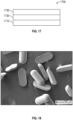
- exemplary assembly 1700 comprises heat source 1710, heat sink 1730, and thermally conductive composition 1720, as described herein at least partially sandwiched between the heat source and the heat sink.
- the shaped thermal filler particles may be present within the thermally conductive composition in any arrangement.
- arrangement refers to the positions and orientations of the shaped thermal filler particles.
- the shaped thermal filler particles within a thermally conductive composition are described herein to be aligned if they are positioned at least approximately along a line.
- the shaped thermal filler particles within a thermally conductive composition are described herein to be oriented if their length directions are approximately parallel with each other.
- the shaped thermal filler particles within the thermally conductive composition sandwiched in an assembly between a heat source and a heat sink are arranged at least approximately in alignment with the heat transport direction.
- the shaped thermal filler particles within the thermally conductive composition sandwiched in an assembly between a heat source and a heat sink are arranged such that their length directions are oriented at least approximately parallel to the heat transport direction.
- the shaped thermal filler particles within the thermally conductive composition sandwiched in an assembly between a heat source and a heat sink are arranged at least approximately in alignment with the heat transport direction and such that their length directions are oriented at least approximately parallel to the heat transport direction.
- the shaped thermal filler particles are preferably randomly arranged in the thermally conductive composition, although this is not a requirement.
- the shaped thermal filler particles are preferably randomly positioned in the thermally conductive composition, although this is not a requirement. In some embodiments, for ease of processing, the shaped thermal filler particles are preferably randomly oriented in the thermally conductive composition, although this is not a requirement.
- randomly oriented shaped particles according to the present disclosure are unexpectedly effective at improving important tradeoffs between thermal energy transfer (e.g., as quantified by effective, or composite, thermal conductivity) and other properties (e.g., density), as compared with known particle shapes such as right cylinders.
- the shaped thermal filler particles may be oriented with respect to each other or the heat transport direction, as described above.
- heat sources include, for example, semiconductor devices (e.g., diodes, integrated circuits, transistors), resistors, inductors, motors, generators, batteries and transformers.
- semiconductor devices e.g., diodes, integrated circuits, transistors
- resistors e.g., resistors, inductors, motors, generators, batteries and transformers.
- Heat sinks are well-known in the art, and are often formed of thermally conductive material (e.g., a metal) having substantial thermal mass relative to the part that they are intended to cool. Often, the heat sink comprises cooling fins and/or posts. Alternatively, some heat sinks may include integral flow channels for the passage of coolant fluid (e.g., water).
- coolant fluid e.g., water
- Particles as defined in TABLE 1 and shown in FIGS. 1A-1D , 2A-2D , and 3A-3D , respectively, were drawn in the CAD software SOLIDWORKS (Dassault Systèmes SolidWorks Corporation, Waltham, Massachusetts). Composites of arrayed particles within bounding boxes were then generated with differing relative particle volumes. Right circular cylinders (shapes D and E ) as defined in Table 1 and generally shown in FIGS. 4A-4D were also modeled as Comparative Modeling Examples and were chosen to match the volume and length to width ratio of the particle of shapes A and C, respectively.
- CAD assemblies were then loaded into ANSYS v 19.1 finite element analysis software (ANSYS, Inc., Canonsburg, Pennsylvania) and the Steady-State Thermal module was used to calculate the effective thermal conductivity of each representative volume.
- ANSYS v 19.1 finite element analysis software
- Steady-State Thermal module was used to calculate the effective thermal conductivity of each representative volume.
- the particles were assigned to have a thermal conductivity of 35 Wm -1 K -1 and the volume around the particles was assigned to have a thermal conductivity of 0.16 Wm -1 K -1 .
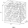
- a CAD geometry was constructed by creating a 3x3x3 array of particles having Shape A, B, or C oriented with their long axes parallel to the x-axis.
- the particle-to-particle spacing in each of the three primary directions ( x, y, z ) is defined as d.
- a bounding box was superimposed on this array such that the distance between each outer particle and the nearest face of the box is d /2 as illustrated in FIG. 5 , 6 , or 7 for Shape A, B, or C, respectively.
- the dimensions of the bounding box are therefore defined by the dimensions of the particles and d.
- Composite volume fraction was varied by changing the value of d while leaving particle dimensions fixed. Variability in composite volume fractions arises from volume variability between particle designs.
- a CAD geometry consisting of an equal distribution of particles oriented with their long axis parallel to each principal direction ( x , y, z ) was constructed.
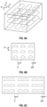
- An array of particles was built by placing either the center of the planar face (shapes A, B, and C ) or the center of volume (shapes D and E ) at the provided coordinates (related to a, the unit cell length), the long axis direction, and the surface normal of the planar face (where applicable) in Table 2.
- a 2 a x 2 a x 2 a bounding box with its origin at (0,0,0) was then superimposed on the array and all particle volumes that exist external to the box are then truncated to the surface of the box as illustrated in FIG. 8 , 9 , 10 , 11 , or 12 for Shape A, B, C, D, or E, respectively.
- the particle-to-particle spacing and thus the volume fraction of particles was adjusted by varying the unit cell length, a .
- the value of a was chosen such that particles did not intersect.
- Shape A was arranged into a 3x3x3 array, uniformly spaced in a bounding box of dimensions 1.314 x 0.720 x 0.510 mm 3 leading to a particle content of 12.5 volume percent and density 1.37 g/cm 3 .
- the particle-to-particle spacing, d was 0.100 mm.
- Shape A was arranged into a 3x3x3 array, uniformly spaced in a bounding box of dimensions 1.164 x 0.570 x 0.360 mm 3 leading to a particle content of 25.3 volume percent and density 1.75 g/cm 3 .
- the particle-to-particle spacing, d was 0.050 mm.
- Shape A was arranged into a 3x3x3 array, uniformly spaced in a bounding box of dimensions 1.044 x 0.450 x 0.240 mm 3 leading to a particle content of 53.7 volume percent and density 2.58 g/cm 3 .
- the particle-to-particle spacing, d was 0.010 mm.
- Shape B was arranged into a 3x3x3 array, uniformly spaced in a bounding box of dimensions 1.314 x 0.720 x 0.510 mm 3 leading to a particle content of 10.0 volume percent and density 1.30 g/cm 3 .
- the particle-to-particle spacing, d was 0.100 mm.
- Shape B was arranged into a 3x3x3 array, uniformly spaced in a bounding box of dimensions 1.164 x 0.570 x 0.360 mm 3 leading to a particle content of 20.2 volume percent and density 1.60 g/cm 3 .
- the particle-to-particle spacing, d was 0.050 mm.
- Shape B was arranged into a 3x3x3 array, uniformly spaced in a bounding box of dimensions 1.044 x 0.450 x 0.240 mm 3 leading to a particle content of 42.8 volume percent and density 2.26 g/cm 3 .
- the particle-to-particle spacing, d was 0.010 mm.
- Shape C was arranged into a 3x3x3 array, uniformly spaced in a bounding box of dimensions 1.314 x 0.720 x 0.510 mm 3 leading to a particle content of 8.7 volume percent and density 1.26 g/cm 3 .
- the particle-to-particle spacing, d was 0.100 mm.
- Shape C was arranged into a 3x3x3 array, uniformly spaced in a bounding box of dimensions 1.164 x 0.570 x 0.360 mm 3 leading to a particle content of 17.6 volume percent and density 1.52 g/cm 3 .
- the particle-to-particle spacing, d was 0.050 mm.
- Shape C is arranged into a 3x3x3 array, uniformly spaced in a bounding box of dimensions 1.044 x 0.450 x 0.240 mm 3 leading to a particle content of 37.2 volume percent and density 2.10 g/cm 3 .
- Shape A was arranged into an array with positions described in Table 2, distributed in a bounding box described by unit dimension, a , of 0.582 mm leading to a particle content of 10.2 volume percent and density 1.30 g/cm 3 .
- Shape A was arranged into an array with positions described in Table 2, distributed in a bounding box described by unit dimension, a , of 0.500 mm leading to a particle content of 16.1 volume percent and density 1.48 g/cm 3 .
- Shape A was arranged into an array with positions described in Table 2, distributed in a bounding box described by unit dimension, a , of 0.436 mm leading to a particle content of 24.3 volume percent and density 1.72 g/cm 3 .
- Shape A was arranged into an array with positions described in Table 2, distributed in a bounding box described by unit dimension, a , of 0.386 mm leading to a particle content of 35.1 volume percent and density 2.04 g/cm 3 .
- Shape B was arranged into an array with positions described in Table 2, distributed in a bounding box described by unit dimension, a , of 0.582 mm leading to a particle content of 8.2 volume percent and density 1.24 g/cm 3 .
- Shape B was arranged into an array with positions described in Table 2, distributed in a bounding box described by unit dimension, a , of 0.500 mm leading to a particle content of 12.9 volume percent and density 1.38 g/cm 3 .
- Shape B was arranged into an array with positions described in Table 2, distributed in a bounding box described by unit dimension, a , of 0.436 mm leading to a particle content of 19.4 volume percent and density 1.57 g/cm 3 .
- Shape B was arranged into an array with positions described in Table 2, distributed in a bounding box described by unit dimension, a, of 0.386 mm leading to a particle content of 28.0 volume percent and density 1.83 g/cm 3 .
- Shape C was arranged into an array with positions described in Table 2, distributed in a bounding box described by unit dimension, a , of 0.582 mm leading to a particle content of 7.1 volume percent and density 1.21 g/cm 3 .
- Shape C was arranged into an array with positions described in Table 2, distributed in a bounding box described by unit dimension, a , of 0.500 mm leading to a particle content of 11.2 volume percent and density 1.33 g/cm 3 .
- Shape C was arranged into an array with positions described in Table 2, distributed in a bounding box described by unit dimension, a, of 0.436 mm leading to a particle content of 16.9 volume percent and density 1.50 g/cm 3 .
- radius and width are determined based on the closed path defining the intersection of the planar surface and the smooth surface and thickness is measured as the length of a vector normal to the planar surface.
- Radius 1 is the radius of curvature of the closed path along the edge of the planar surface at the end of the length of the shape.
- Radius 2 is the radius of curvature along the closed path from the planar surface to the maximum thickness along the long axis of the shape.
- Radius 3 is the radius of curvature along the maximum width of the particle from one planar surface to the other.
- Radius 4 is the radius of curvature that defines the necking region at the waist along the planar surface edge.
- Particles B and C have waist width, as percentages of their particle widths, of 70% and 41.4%, respectively.
- Particles Band C have waist thickness, as percentages of their particle thicknesses, of 70% and 41.4%, respectively.
- WIDTH 0.140 0.140 0.140 0.106 0.094 WAIST WIDTH NA 0.098 0.058 NA NA THICKNESS 0.070 0.070 0.070 NA NA WAIST THICKNESS NA 0.049 0.029 NA NA
- Shape D was arranged into an array with positions described in Table 2, distributed in a bounding box described by unit dimension, a , of 0.436 mm leading to a particle content of 16.1 volume percent and density 1.48 g/cm 3 .
- Shape E was arranged into an array with positions described in Table 2, distributed in a bounding box described by unit dimension, a , of 0.386 mm leading to a particle content of 11.2 volume percent and density 1.33 g/cm 3 .
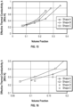
- FIG. 14 shows the effective thermal conductivity as an average of three orthogonal axes (x, y, and z) for composites comprising Shapes A, B, and C in an oriented array.
- the volume fraction of particles required to obtain comparable effective thermal conductivities in composites comprising Shape C is lower than that required for composites comprising Shape B, which is still lower than that required for composites comprising Shape A.
- FIG. 15 shows the effective thermal conductivity as an average along three orthogonal axes (x, y, and z) for composites comprising Shapes A, B, and C in an array comprising particles equally oriented along x, y, and z axes as reported in Table 2.
- FIGS. 8 , 9 , or 10 A representative arrangement of this specific array for Shape A, B, or C is presented in FIGS. 8 , 9 , or 10 , respectively. Note that because the overall orientation of particles in the array is not biased in any of the three principal directions, the effective thermal conductivity is identical when measured along any of the three pairs of opposing faces of the bounding box. The volume fraction of particles required to obtain comparable effective thermal conductivities in composites comprising Shape C is lower than that required for composites comprising Shape B, which is still lower than that required for composites comprising Shape A.
- FIG. 16 shows the effective thermal conductivity as an average along three orthogonal axes (x, y, and z) for composites comprising Shapes A, C, D, and E in an array comprising particles equally oriented along one of the x, y, and z axes.
- a representative arrangement of this specific array for Shape A, C, D, or E is presented in FIGS. 8 , 10 , 11 , or 12 , respectively.
- the aspect ratio for Shapes D and E are identical to those of Shapes A and C, respectively. From this, composites comprising the particles of shape described by this disclosure (Shapes A and C) have a higher effective thermal conductivity at a given volume fraction than comparative Shapes D and E.
- Shaped alumina particles were produced from an aqueous suspension of alumina in water with binder and dispersant using components and amounts reported in Table 4, below.
- TABLE 4 ABBREVIATION SOURCE AMOUNT, grams Water 196.17 Alumina Aluminum (III) Oxide available from Almatis Inc., Bauxite, Arkansas as RG4000 588.52 Sodium Polymethacrylate Solution Sodium Polymethacrylate Solution obtained from Geo Specialty Chemicals, Ambler, Pennsylvania, as DAXAD 30 11.77 Cell gum Sodium carboxymethylcellulose, obtained from Ashland, Columbus, Ohio, as BLANOSE REF CMC 7ULC 5.89
- Shaped alumina particles were produced by making an aqueous suspension of alumina in water with binder and dispersant.
- the cell gum was added to the water very slowly first and fully dissolved with aggressive high shear mixing.
- the sodium polymethacrylate solution was added before the alumina was added last.
- the mixture was transferred to a 1.8 L ball mill (obtained as ROALAX from U.S. Stoneware, East furniture, Ohio, ) with 1 cm cylindrical alumina media (obtained as BURUNDUM from U.S. Stoneware) half filling the jar for 24 hours at 175 revolutions per minute to make a homogeneous suspension.
- Molded precursor green particles were made from the suspension generally as described in U.S. Pat. No. 8,701,441 (Kramlich, et. al.) .
- the mold used had the dimensions defined for Shape A in Table 1.
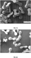
- FIG. 18 shows the resulting molded precursor particles
- the molded precursor particles were placed in an alumina combustion boat (obtained as AL-5020 from AdValue Technology, Arlington, Arizona) and the boat with particles was put into a rapid fire furnace (obtained as 1708 BL from CM Furnaces, Inc., Bloomfield, New Jersey).
- the furnace temperature was increased at 10 degrees Celsius (°C) per minute to a set point of 1400 °C where the temperature was held for 6 hours before decreasing to room temperature at 10 °C per minute.
- Shaped thermal filler particles were prepared as in Working Example 1, except that Shape B was used instead of Shape A.
- FIG. 19 shows the resulting molded precursor particles.
- Shaped thermal filler particles were prepared as in Working Example 1, except that Shape C was used instead of Shape A.
- FIG. 20 shows the resulting molded precursor particles.
Landscapes
- Chemical & Material Sciences (AREA)
- Engineering & Computer Science (AREA)
- Organic Chemistry (AREA)
- Chemical Kinetics & Catalysis (AREA)
- Materials Engineering (AREA)
- Thermal Sciences (AREA)
- Physics & Mathematics (AREA)
- Combustion & Propulsion (AREA)
- Health & Medical Sciences (AREA)
- Medicinal Chemistry (AREA)
- Polymers & Plastics (AREA)
- Cooling Or The Like Of Semiconductors Or Solid State Devices (AREA)
- Compositions Of Macromolecular Compounds (AREA)
- Powder Metallurgy (AREA)
Claims (15)
- Ein geformtes Teilchen von thermischem Füllstoff, das eine längliche Form aufweist, die durch eine ebene erste glatte Oberfläche, eine zweite glatte Oberfläche, die die ebene erste glatte Oberfläche entlang eines geschlossenen Pfads berührt, definiert ist, wobei mindestens ein Abschnitt der zweiten glatten Oberfläche konvex ist, wobei der geschlossene Pfad ein Längen-Breiten-Verhältnis von mindestens 1,5 aufweist und wobei das geformte Teilchen von thermischem Füllstoff eine maximale lineare Abmessung normal zu der ebenen ersten glatten Oberfläche aufweist, die kleiner als oder gleich einer Hälfte der Länge des geschlossenen Pfads ist.
- Das geformte Teilchen von thermischem Füllstoff nach Anspruch 1, wobei der geschlossene Pfad zwei abgerundete Enden und ein dazwischen eingerichtetes, relativ schmaleres Mittelstück aufweist.
- Das geformte Teilchen von thermischem Füllstoff nach Anspruch 1, wobei der geschlossene Pfad zwei halbkreisförmige Enden aufweist, die durch zwei parallele Liniensegmente verbunden sind.
- Das geformte Teilchen von thermischem Füllstoff nach Anspruch 1, wobei die zweite glatte Oberfläche vollständig konvex ist.
- Das geformte Teilchen von thermischem Füllstoff nach einem der Ansprüche 1 bis 4, wobei das geformte Teilchen von thermischem Füllstoff eine Wärmeleitfähigkeit von mindestens 1 Wm-1K-1 aufweist.
- Das geformte Teilchen von thermischem Füllstoff nach einem der Ansprüche 1 bis 5, wobei das geformte Teilchen von thermischem Füllstoff mindestens eines von Aluminiumoxid, Magnesiumoxid, Aluminiumhydroxid, Zinkoxid, Bornitrid oder Aluminiumnitrid umfasst.
- Das geformte Teilchen von thermischem Füllstoff nach einem der Ansprüche 1 bis 6, wobei das geformte Teilchen von thermischem Füllstoff anorganisch ist.
- Das geformte Teilchen von thermischem Füllstoff nach Anspruch 7, wobei das geformte Teilchen von thermischem Füllstoff aus Keramik besteht.
- Das geformte Teilchen von thermischem Füllstoff nach einem der Ansprüche 1 bis 8, wobei das geformte Teilchen von thermischem Füllstoff eine homogene Zusammensetzung aufweist.
- Eine wärmeleitfähige Zusammensetzung, umfassend von zu 1 bis 95 Volumenprozent geformte Teilchen von thermischem Füllstoff nach einem der Ansprüche 1 bis 9, die in einem organischen Bindemittel dispergiert sind.
- Die wärmeleitfähige Zusammensetzung nach Anspruch 10, wobei die wärmeleitfähige Zusammensetzung gehärtet oder chemisch vernetzt ist.
- Die wärmeleitfähige Zusammensetzung nach Anspruch 10, wobei die wärmeleitfähige Zusammensetzung ein Fett umfasst.
- Die wärmeleitfähige Zusammensetzung nach einem der Ansprüche 10 bis 12, ferner umfassend sekundäre wärmeleitfähige Teilchen.
- Die wärmeleitfähige Zusammensetzung nach einem der Ansprüche 10 bis 13, wobei die geformten wärmeleitfähigen Teilchen zufällig ausgerichtet sind.
- Eine Anordnung, umfassend:eine Heizquelle;einen Kühlkörper; unddie wärmeleitfähige Zusammensetzung nach einem der Ansprüche 11 bis 14, die zwischen der Heizquelle und dem Kühlkörper mindestens teilweise eingeschoben ist.
Applications Claiming Priority (2)
| Application Number | Priority Date | Filing Date | Title |
|---|---|---|---|
| US202063057655P | 2020-07-28 | 2020-07-28 | |
| PCT/IB2021/056644 WO2022023900A1 (en) | 2020-07-28 | 2021-07-22 | Thermal filler particle, thermally conductive composition, and assembly including the same |
Publications (2)
| Publication Number | Publication Date |
|---|---|
| EP4189031A1 EP4189031A1 (de) | 2023-06-07 |
| EP4189031B1 true EP4189031B1 (de) | 2024-08-28 |
Family
ID=77126875
Family Applications (1)
| Application Number | Title | Priority Date | Filing Date |
|---|---|---|---|
| EP21748677.8A Active EP4189031B1 (de) | 2020-07-28 | 2021-07-22 | Thermisches füllstoffpartikel, wärmeleitende zusammensetzung und anordnung damit |
Country Status (4)
| Country | Link |
|---|---|
| US (1) | US12410303B2 (de) |
| EP (1) | EP4189031B1 (de) |
| JP (1) | JP7837313B2 (de) |
| WO (1) | WO2022023900A1 (de) |
Family Cites Families (29)
| Publication number | Priority date | Publication date | Assignee | Title |
|---|---|---|---|---|
| US5549962A (en) | 1993-06-30 | 1996-08-27 | Minnesota Mining And Manufacturing Company | Precisely shaped particles and method of making the same |
| US6585039B2 (en) | 2000-02-01 | 2003-07-01 | Cool Options, Inc. | Composite overmolded heat pipe construction |
| US6851869B2 (en) | 2000-08-04 | 2005-02-08 | Cool Options, Inc. | Highly thermally conductive electronic connector |
| US7208192B2 (en) * | 2002-05-31 | 2007-04-24 | Parker-Hannifin Corporation | Thermally or electrically-conductive form-in-place gap filter |
| EP1998844A4 (de) | 2006-03-24 | 2017-03-01 | 3M Innovative Properties Company | Verfahren zur herstellung von mikronadeln, mikronadelanordnung, vorlage und replikationswerkzeug |
| CN2921526Y (zh) | 2006-07-04 | 2007-07-11 | 范兴宽 | 高抗冲击内衬陶瓷复合弯管 |
| US8701441B2 (en) | 2006-08-21 | 2014-04-22 | 3M Innovative Properties Company | Method of making inorganic, metal oxide spheres using microstructured molds |
| JP5274007B2 (ja) | 2007-12-27 | 2013-08-28 | 三菱電機株式会社 | 熱伝導性樹脂シートおよびこれを用いたパワーモジュール |
| US8142891B2 (en) | 2008-12-17 | 2012-03-27 | 3M Innovative Properties Company | Dish-shaped abrasive particles with a recessed surface |
| JP2011021069A (ja) | 2009-07-14 | 2011-02-03 | Sakai Chem Ind Co Ltd | 放熱性フィラー組成物、樹脂組成物、放熱性グリース及び放熱性塗料組成物 |
| EP3858800B1 (de) | 2011-07-12 | 2024-07-24 | 3M Innovative Properties Co. | Geformte keramikschleifpartikel |
| US10315289B2 (en) | 2013-12-09 | 2019-06-11 | 3M Innovative Properties Company | Conglomerate abrasive particles, abrasive articles including the same, and methods of making the same |
| JP6715764B2 (ja) * | 2014-04-23 | 2020-07-01 | 日本碍子株式会社 | 多孔質板状フィラー、その製造方法、及び断熱膜 |
| US9611414B2 (en) | 2014-07-11 | 2017-04-04 | Henkel IP & Holding GmbH | Thermal interface material with mixed aspect ratio particle dispersions |
| CN104513487B (zh) | 2014-12-10 | 2017-05-10 | 东莞兆舜有机硅科技股份有限公司 | 一种双组分导热硅凝胶及其用途 |
| CN105255163A (zh) | 2015-09-16 | 2016-01-20 | 安徽省和翰光电科技有限公司 | 一种led用纳米硅-四针状氧化锌晶须填充改性的pa6/abs复合导热塑料及其制备方法 |
| WO2017155779A1 (en) | 2016-03-07 | 2017-09-14 | 3M Innovative Properties Company | Vacuum glazing pillars for insulated glass units and insulated glass units therefrom |
| WO2017155687A1 (en) | 2016-03-07 | 2017-09-14 | 3M Innovative Properties Company | Vacuum glazing pillars for insulated glass units and insulated glass units therefrom |
| CN106278199B (zh) | 2016-08-10 | 2019-02-05 | 山东天汇研磨耐磨技术开发有限公司 | 一种内置纯钛或α钛合金骨架的陶瓷球及其制备方法 |
| EP3352290B1 (de) | 2017-01-19 | 2024-07-17 | 3M Innovative Properties Company | Aziridinfunktionales wärmeleitendes polyether-spaltenfüllmaterial |
| US10759024B2 (en) | 2017-01-31 | 2020-09-01 | Saint-Gobain Ceramics & Plastics, Inc. | Abrasive article including shaped abrasive particles |
| CN107603224B (zh) | 2017-09-14 | 2021-01-12 | 中国科学院工程热物理研究所 | 一种高热导率低粘度的导热硅脂组合物及其制备方法 |
| WO2019069157A1 (en) | 2017-10-02 | 2019-04-11 | 3M Innovative Properties Company | ELONGATED ABRASIVE PARTICLES, PROCESS FOR PRODUCTION THEREOF, AND ABRASIVE ARTICLES CONTAINING THE SAME |
| CN108250747B (zh) | 2018-01-15 | 2021-11-09 | 北京工商大学 | 一种热塑性聚醚酰亚胺绝缘导热复合材料及其制备方法 |
| WO2019189746A1 (ja) * | 2018-03-30 | 2019-10-03 | 三菱ケミカル株式会社 | 放熱シート、放熱部材及び半導体デバイス |
| CN108546414A (zh) | 2018-05-18 | 2018-09-18 | 深圳市金菱通达电子有限公司 | 新能源电池专用的轻量化导热材料 |
| WO2020115451A1 (en) * | 2018-12-03 | 2020-06-11 | Loughborough University | Composite material |
| CN109574649A (zh) | 2018-12-14 | 2019-04-05 | 镭米光学科技(宁波)有限公司 | 一种钇铝石榴石透明陶瓷的制备方法 |
| EP3969507A1 (de) | 2019-05-15 | 2022-03-23 | 3M Innovative Properties Company | (co)polymermatrixkomposite mit thermisch leitfähigen teilchen und einem nichtflüchtigen verdünnungsmittel und verfahren zu ihrer herstellung |
-
2021
- 2021-07-22 EP EP21748677.8A patent/EP4189031B1/de active Active
- 2021-07-22 US US18/014,783 patent/US12410303B2/en active Active
- 2021-07-22 JP JP2023505669A patent/JP7837313B2/ja active Active
- 2021-07-22 WO PCT/IB2021/056644 patent/WO2022023900A1/en not_active Ceased
Also Published As
| Publication number | Publication date |
|---|---|
| EP4189031A1 (de) | 2023-06-07 |
| US12410303B2 (en) | 2025-09-09 |
| WO2022023900A1 (en) | 2022-02-03 |
| US20240239991A1 (en) | 2024-07-18 |
| JP2023536573A (ja) | 2023-08-28 |
| JP7837313B2 (ja) | 2026-03-30 |
Similar Documents
| Publication | Publication Date | Title |
|---|---|---|
| US10919760B2 (en) | Process for nano graphene platelet-reinforced composite material | |
| EP2195374B1 (de) | Wärmeverarbeitbare wärmeleitende polymerzusammensetzung | |
| KR100450831B1 (ko) | 열전도성 복합재료 | |
| EP3419399B1 (de) | Wärmeleitfolie | |
| US6503626B1 (en) | Graphite-based heat sink | |
| EP2296454B1 (de) | Wärmekontrollsystem | |
| CN111492474B (zh) | 绝缘散热片 | |
| CN108495897B (zh) | 热传导性树脂成型品 | |
| JP6023474B2 (ja) | 熱伝導性絶縁シート、金属ベース基板及び回路基板、及びその製造方法 | |
| US10736237B2 (en) | Heat sink, preparation method therefor, and communications device | |
| EP1956110A1 (de) | Auf metall basierender verbundwerkstoff, enthaltend sowohl mikroskalige kohlefaser als auch nanoskalige kohlefaser | |
| US20160186031A1 (en) | Carbon composites having high thermal conductivity, articles thereof, and methods of manufacture | |
| CN105263886A (zh) | 树脂浸渗氮化硼烧结体及其用途 | |
| Chang et al. | A reduced percolation threshold of hybrid fillers of ball-milled exfoliated graphite nanoplatelets and AgNWs for enhanced thermal interface materials in high power electronics | |
| EP3702399B1 (de) | Verbundwerkstoff | |
| Wang et al. | GMP/Al2O3/ZnO/PDMS thermal interface materials with anisotropic thermal conductivity and electrical insulation ability obtained by 3D‐printing method | |
| KR102768721B1 (ko) | 육방정계 질화붕소를 이용한 열전도성 복합소재 | |
| US12410303B2 (en) | Thermal filler particle, thermally conductive composition, and assembly including the same | |
| EP4578969A1 (de) | Metall- und/oder keramik/graphithaltiger aluminiumverbundwerkstoff und verfahren zur herstellung eines metall- und/oder keramik/graphithaltigen aluminiumverbundwerkstoffs | |
| KR102843818B1 (ko) | 열전도성 시트 | |
| KR101967856B1 (ko) | 고열전도성 필름 및 그 제조 방법 | |
| JP7308636B2 (ja) | 窒化アルミニウムからなる複合構造体 | |
| Jiang et al. | Constructing Highly Ordered Hybrid Carbon Networks in SR Composites to Achieve Excellent Bi-directional Thermal Conduction | |
| JP7785025B2 (ja) | 流動性硬化性組成物、熱伝導性組成物、及びそれらを含む電子ヒートシンクアセンブリ | |
| KR20130090984A (ko) | 압연 및 프레스 공정에 의해 압입된 다이아몬드 입자와 금속의 복합소재 방열기판 |
Legal Events
| Date | Code | Title | Description |
|---|---|---|---|
| STAA | Information on the status of an ep patent application or granted ep patent |
Free format text: STATUS: UNKNOWN |
|
| STAA | Information on the status of an ep patent application or granted ep patent |
Free format text: STATUS: THE INTERNATIONAL PUBLICATION HAS BEEN MADE |
|
| PUAI | Public reference made under article 153(3) epc to a published international application that has entered the european phase |
Free format text: ORIGINAL CODE: 0009012 |
|
| STAA | Information on the status of an ep patent application or granted ep patent |
Free format text: STATUS: REQUEST FOR EXAMINATION WAS MADE |
|
| 17P | Request for examination filed |
Effective date: 20230111 |
|
| AK | Designated contracting states |
Kind code of ref document: A1 Designated state(s): AL AT BE BG CH CY CZ DE DK EE ES FI FR GB GR HR HU IE IS IT LI LT LU LV MC MK MT NL NO PL PT RO RS SE SI SK SM TR |
|
| DAV | Request for validation of the european patent (deleted) | ||
| DAX | Request for extension of the european patent (deleted) | ||
| GRAP | Despatch of communication of intention to grant a patent |
Free format text: ORIGINAL CODE: EPIDOSNIGR1 |
|
| STAA | Information on the status of an ep patent application or granted ep patent |
Free format text: STATUS: GRANT OF PATENT IS INTENDED |
|
| INTG | Intention to grant announced |
Effective date: 20240415 |
|
| GRAS | Grant fee paid |
Free format text: ORIGINAL CODE: EPIDOSNIGR3 |
|
| GRAA | (expected) grant |
Free format text: ORIGINAL CODE: 0009210 |
|
| STAA | Information on the status of an ep patent application or granted ep patent |
Free format text: STATUS: THE PATENT HAS BEEN GRANTED |
|
| P01 | Opt-out of the competence of the unified patent court (upc) registered |
Free format text: CASE NUMBER: APP_41867/2024 Effective date: 20240716 |
|
| AK | Designated contracting states |
Kind code of ref document: B1 Designated state(s): AL AT BE BG CH CY CZ DE DK EE ES FI FR GB GR HR HU IE IS IT LI LT LU LV MC MK MT NL NO PL PT RO RS SE SI SK SM TR |
|
| REG | Reference to a national code |
Ref country code: CH Ref legal event code: EP |
|
| REG | Reference to a national code |
Ref country code: DE Ref legal event code: R096 Ref document number: 602021017985 Country of ref document: DE |
|
| REG | Reference to a national code |
Ref country code: IE Ref legal event code: FG4D |
|
| REG | Reference to a national code |
Ref country code: LT Ref legal event code: MG9D |
|
| PG25 | Lapsed in a contracting state [announced via postgrant information from national office to epo] |
Ref country code: NO Free format text: LAPSE BECAUSE OF FAILURE TO SUBMIT A TRANSLATION OF THE DESCRIPTION OR TO PAY THE FEE WITHIN THE PRESCRIBED TIME-LIMIT Effective date: 20241128 |
|
| REG | Reference to a national code |
Ref country code: AT Ref legal event code: MK05 Ref document number: 1717961 Country of ref document: AT Kind code of ref document: T Effective date: 20240828 |
|
| PG25 | Lapsed in a contracting state [announced via postgrant information from national office to epo] |
Ref country code: NL Free format text: LAPSE BECAUSE OF FAILURE TO SUBMIT A TRANSLATION OF THE DESCRIPTION OR TO PAY THE FEE WITHIN THE PRESCRIBED TIME-LIMIT Effective date: 20240828 Ref country code: GR Free format text: LAPSE BECAUSE OF FAILURE TO SUBMIT A TRANSLATION OF THE DESCRIPTION OR TO PAY THE FEE WITHIN THE PRESCRIBED TIME-LIMIT Effective date: 20241129 Ref country code: FI Free format text: LAPSE BECAUSE OF FAILURE TO SUBMIT A TRANSLATION OF THE DESCRIPTION OR TO PAY THE FEE WITHIN THE PRESCRIBED TIME-LIMIT Effective date: 20240828 Ref country code: PT Free format text: LAPSE BECAUSE OF FAILURE TO SUBMIT A TRANSLATION OF THE DESCRIPTION OR TO PAY THE FEE WITHIN THE PRESCRIBED TIME-LIMIT Effective date: 20241230 Ref country code: PL Free format text: LAPSE BECAUSE OF FAILURE TO SUBMIT A TRANSLATION OF THE DESCRIPTION OR TO PAY THE FEE WITHIN THE PRESCRIBED TIME-LIMIT Effective date: 20240828 |
|
| PG25 | Lapsed in a contracting state [announced via postgrant information from national office to epo] |
Ref country code: BG Free format text: LAPSE BECAUSE OF FAILURE TO SUBMIT A TRANSLATION OF THE DESCRIPTION OR TO PAY THE FEE WITHIN THE PRESCRIBED TIME-LIMIT Effective date: 20240828 |
|
| PG25 | Lapsed in a contracting state [announced via postgrant information from national office to epo] |
Ref country code: LV Free format text: LAPSE BECAUSE OF FAILURE TO SUBMIT A TRANSLATION OF THE DESCRIPTION OR TO PAY THE FEE WITHIN THE PRESCRIBED TIME-LIMIT Effective date: 20240828 |
|
| REG | Reference to a national code |
Ref country code: NL Ref legal event code: MP Effective date: 20240828 |
|
| PG25 | Lapsed in a contracting state [announced via postgrant information from national office to epo] |
Ref country code: IS Free format text: LAPSE BECAUSE OF FAILURE TO SUBMIT A TRANSLATION OF THE DESCRIPTION OR TO PAY THE FEE WITHIN THE PRESCRIBED TIME-LIMIT Effective date: 20241228 Ref country code: AT Free format text: LAPSE BECAUSE OF FAILURE TO SUBMIT A TRANSLATION OF THE DESCRIPTION OR TO PAY THE FEE WITHIN THE PRESCRIBED TIME-LIMIT Effective date: 20240828 |
|
| PG25 | Lapsed in a contracting state [announced via postgrant information from national office to epo] |
Ref country code: HR Free format text: LAPSE BECAUSE OF FAILURE TO SUBMIT A TRANSLATION OF THE DESCRIPTION OR TO PAY THE FEE WITHIN THE PRESCRIBED TIME-LIMIT Effective date: 20240828 |
|
| PG25 | Lapsed in a contracting state [announced via postgrant information from national office to epo] |
Ref country code: ES Free format text: LAPSE BECAUSE OF FAILURE TO SUBMIT A TRANSLATION OF THE DESCRIPTION OR TO PAY THE FEE WITHIN THE PRESCRIBED TIME-LIMIT Effective date: 20240828 Ref country code: RS Free format text: LAPSE BECAUSE OF FAILURE TO SUBMIT A TRANSLATION OF THE DESCRIPTION OR TO PAY THE FEE WITHIN THE PRESCRIBED TIME-LIMIT Effective date: 20241128 |
|
| PG25 | Lapsed in a contracting state [announced via postgrant information from national office to epo] |
Ref country code: RS Free format text: LAPSE BECAUSE OF FAILURE TO SUBMIT A TRANSLATION OF THE DESCRIPTION OR TO PAY THE FEE WITHIN THE PRESCRIBED TIME-LIMIT Effective date: 20241128 Ref country code: PT Free format text: LAPSE BECAUSE OF FAILURE TO SUBMIT A TRANSLATION OF THE DESCRIPTION OR TO PAY THE FEE WITHIN THE PRESCRIBED TIME-LIMIT Effective date: 20241230 Ref country code: PL Free format text: LAPSE BECAUSE OF FAILURE TO SUBMIT A TRANSLATION OF THE DESCRIPTION OR TO PAY THE FEE WITHIN THE PRESCRIBED TIME-LIMIT Effective date: 20240828 Ref country code: NO Free format text: LAPSE BECAUSE OF FAILURE TO SUBMIT A TRANSLATION OF THE DESCRIPTION OR TO PAY THE FEE WITHIN THE PRESCRIBED TIME-LIMIT Effective date: 20241128 Ref country code: NL Free format text: LAPSE BECAUSE OF FAILURE TO SUBMIT A TRANSLATION OF THE DESCRIPTION OR TO PAY THE FEE WITHIN THE PRESCRIBED TIME-LIMIT Effective date: 20240828 Ref country code: LV Free format text: LAPSE BECAUSE OF FAILURE TO SUBMIT A TRANSLATION OF THE DESCRIPTION OR TO PAY THE FEE WITHIN THE PRESCRIBED TIME-LIMIT Effective date: 20240828 Ref country code: IS Free format text: LAPSE BECAUSE OF FAILURE TO SUBMIT A TRANSLATION OF THE DESCRIPTION OR TO PAY THE FEE WITHIN THE PRESCRIBED TIME-LIMIT Effective date: 20241228 Ref country code: HR Free format text: LAPSE BECAUSE OF FAILURE TO SUBMIT A TRANSLATION OF THE DESCRIPTION OR TO PAY THE FEE WITHIN THE PRESCRIBED TIME-LIMIT Effective date: 20240828 Ref country code: GR Free format text: LAPSE BECAUSE OF FAILURE TO SUBMIT A TRANSLATION OF THE DESCRIPTION OR TO PAY THE FEE WITHIN THE PRESCRIBED TIME-LIMIT Effective date: 20241129 Ref country code: FI Free format text: LAPSE BECAUSE OF FAILURE TO SUBMIT A TRANSLATION OF THE DESCRIPTION OR TO PAY THE FEE WITHIN THE PRESCRIBED TIME-LIMIT Effective date: 20240828 Ref country code: ES Free format text: LAPSE BECAUSE OF FAILURE TO SUBMIT A TRANSLATION OF THE DESCRIPTION OR TO PAY THE FEE WITHIN THE PRESCRIBED TIME-LIMIT Effective date: 20240828 Ref country code: BG Free format text: LAPSE BECAUSE OF FAILURE TO SUBMIT A TRANSLATION OF THE DESCRIPTION OR TO PAY THE FEE WITHIN THE PRESCRIBED TIME-LIMIT Effective date: 20240828 Ref country code: AT Free format text: LAPSE BECAUSE OF FAILURE TO SUBMIT A TRANSLATION OF THE DESCRIPTION OR TO PAY THE FEE WITHIN THE PRESCRIBED TIME-LIMIT Effective date: 20240828 |
|
| PG25 | Lapsed in a contracting state [announced via postgrant information from national office to epo] |
Ref country code: RO Free format text: LAPSE BECAUSE OF FAILURE TO SUBMIT A TRANSLATION OF THE DESCRIPTION OR TO PAY THE FEE WITHIN THE PRESCRIBED TIME-LIMIT Effective date: 20240828 Ref country code: DK Free format text: LAPSE BECAUSE OF FAILURE TO SUBMIT A TRANSLATION OF THE DESCRIPTION OR TO PAY THE FEE WITHIN THE PRESCRIBED TIME-LIMIT Effective date: 20240828 Ref country code: SM Free format text: LAPSE BECAUSE OF FAILURE TO SUBMIT A TRANSLATION OF THE DESCRIPTION OR TO PAY THE FEE WITHIN THE PRESCRIBED TIME-LIMIT Effective date: 20240828 |
|
| PG25 | Lapsed in a contracting state [announced via postgrant information from national office to epo] |
Ref country code: EE Free format text: LAPSE BECAUSE OF FAILURE TO SUBMIT A TRANSLATION OF THE DESCRIPTION OR TO PAY THE FEE WITHIN THE PRESCRIBED TIME-LIMIT Effective date: 20240828 |
|
| PG25 | Lapsed in a contracting state [announced via postgrant information from national office to epo] |
Ref country code: CZ Free format text: LAPSE BECAUSE OF FAILURE TO SUBMIT A TRANSLATION OF THE DESCRIPTION OR TO PAY THE FEE WITHIN THE PRESCRIBED TIME-LIMIT Effective date: 20240828 |
|
| PG25 | Lapsed in a contracting state [announced via postgrant information from national office to epo] |
Ref country code: SK Free format text: LAPSE BECAUSE OF FAILURE TO SUBMIT A TRANSLATION OF THE DESCRIPTION OR TO PAY THE FEE WITHIN THE PRESCRIBED TIME-LIMIT Effective date: 20240828 Ref country code: IT Free format text: LAPSE BECAUSE OF FAILURE TO SUBMIT A TRANSLATION OF THE DESCRIPTION OR TO PAY THE FEE WITHIN THE PRESCRIBED TIME-LIMIT Effective date: 20240828 |
|
| REG | Reference to a national code |
Ref country code: DE Ref legal event code: R097 Ref document number: 602021017985 Country of ref document: DE |
|
| PLBE | No opposition filed within time limit |
Free format text: ORIGINAL CODE: 0009261 |
|
| STAA | Information on the status of an ep patent application or granted ep patent |
Free format text: STATUS: NO OPPOSITION FILED WITHIN TIME LIMIT |
|
| 26N | No opposition filed |
Effective date: 20250530 |
|
| PG25 | Lapsed in a contracting state [announced via postgrant information from national office to epo] |
Ref country code: SE Free format text: LAPSE BECAUSE OF FAILURE TO SUBMIT A TRANSLATION OF THE DESCRIPTION OR TO PAY THE FEE WITHIN THE PRESCRIBED TIME-LIMIT Effective date: 20240828 |
|
| PGFP | Annual fee paid to national office [announced via postgrant information from national office to epo] |
Ref country code: DE Payment date: 20250620 Year of fee payment: 5 |
|
| REG | Reference to a national code |
Ref country code: CH Ref legal event code: H13 Free format text: ST27 STATUS EVENT CODE: U-0-0-H10-H13 (AS PROVIDED BY THE NATIONAL OFFICE) Effective date: 20260224 |
|
| PG25 | Lapsed in a contracting state [announced via postgrant information from national office to epo] |
Ref country code: LU Free format text: LAPSE BECAUSE OF NON-PAYMENT OF DUE FEES Effective date: 20250722 |
|
| GBPC | Gb: european patent ceased through non-payment of renewal fee |
Effective date: 20250722 |
|
| REG | Reference to a national code |
Ref country code: BE Ref legal event code: MM Effective date: 20250731 |
|
| PG25 | Lapsed in a contracting state [announced via postgrant information from national office to epo] |
Ref country code: GB Free format text: LAPSE BECAUSE OF NON-PAYMENT OF DUE FEES Effective date: 20250722 |
|
| PG25 | Lapsed in a contracting state [announced via postgrant information from national office to epo] |
Ref country code: BE Free format text: LAPSE BECAUSE OF NON-PAYMENT OF DUE FEES Effective date: 20250731 |
|
| PG25 | Lapsed in a contracting state [announced via postgrant information from national office to epo] |
Ref country code: FR Free format text: LAPSE BECAUSE OF NON-PAYMENT OF DUE FEES Effective date: 20250731 |
|
| PG25 | Lapsed in a contracting state [announced via postgrant information from national office to epo] |
Ref country code: CH Free format text: LAPSE BECAUSE OF NON-PAYMENT OF DUE FEES Effective date: 20250731 |