EP4188076B1 - Coanda-effekt-durchflussverstärker und lufteinrichtung beinhaltend einen solchen durchflussverstärker - Google Patents
Coanda-effekt-durchflussverstärker und lufteinrichtung beinhaltend einen solchen durchflussverstärker Download PDFInfo
- Publication number
- EP4188076B1 EP4188076B1 EP21756020.0A EP21756020A EP4188076B1 EP 4188076 B1 EP4188076 B1 EP 4188076B1 EP 21756020 A EP21756020 A EP 21756020A EP 4188076 B1 EP4188076 B1 EP 4188076B1
- Authority
- EP
- European Patent Office
- Prior art keywords
- flow
- injection
- orifices
- flow amplifier
- injection orifice
- Prior art date
- Legal status (The legal status is an assumption and is not a legal conclusion. Google has not performed a legal analysis and makes no representation as to the accuracy of the status listed.)
- Active
Links
Images
Classifications
-
- F—MECHANICAL ENGINEERING; LIGHTING; HEATING; WEAPONS; BLASTING
- F04—POSITIVE - DISPLACEMENT MACHINES FOR LIQUIDS; PUMPS FOR LIQUIDS OR ELASTIC FLUIDS
- F04F—PUMPING OF FLUID BY DIRECT CONTACT OF ANOTHER FLUID OR BY USING INERTIA OF FLUID TO BE PUMPED; SIPHONS
- F04F5/00—Jet pumps, i.e. devices in which flow is induced by pressure drop caused by velocity of another fluid flow
- F04F5/44—Component parts, details, or accessories not provided for in, or of interest apart from, groups F04F5/02 - F04F5/42
- F04F5/46—Arrangements of nozzles
-
- A—HUMAN NECESSITIES
- A01—AGRICULTURE; FORESTRY; ANIMAL HUSBANDRY; HUNTING; TRAPPING; FISHING
- A01H—NEW PLANTS OR NON-TRANSGENIC PROCESSES FOR OBTAINING THEM; PLANT REPRODUCTION BY TISSUE CULTURE TECHNIQUES
- A01H1/00—Processes for modifying genotypes ; Plants characterised by associated natural traits
- A01H1/02—Methods or apparatus for hybridisation; Artificial pollination ; Fertility
- A01H1/027—Apparatus for pollination
-
- F—MECHANICAL ENGINEERING; LIGHTING; HEATING; WEAPONS; BLASTING
- F04—POSITIVE - DISPLACEMENT MACHINES FOR LIQUIDS; PUMPS FOR LIQUIDS OR ELASTIC FLUIDS
- F04F—PUMPING OF FLUID BY DIRECT CONTACT OF ANOTHER FLUID OR BY USING INERTIA OF FLUID TO BE PUMPED; SIPHONS
- F04F5/00—Jet pumps, i.e. devices in which flow is induced by pressure drop caused by velocity of another fluid flow
- F04F5/14—Jet pumps, i.e. devices in which flow is induced by pressure drop caused by velocity of another fluid flow the inducing fluid being elastic fluid
- F04F5/16—Jet pumps, i.e. devices in which flow is induced by pressure drop caused by velocity of another fluid flow the inducing fluid being elastic fluid displacing elastic fluids
- F04F5/18—Jet pumps, i.e. devices in which flow is induced by pressure drop caused by velocity of another fluid flow the inducing fluid being elastic fluid displacing elastic fluids for compressing
-
- F—MECHANICAL ENGINEERING; LIGHTING; HEATING; WEAPONS; BLASTING
- F04—POSITIVE - DISPLACEMENT MACHINES FOR LIQUIDS; PUMPS FOR LIQUIDS OR ELASTIC FLUIDS
- F04F—PUMPING OF FLUID BY DIRECT CONTACT OF ANOTHER FLUID OR BY USING INERTIA OF FLUID TO BE PUMPED; SIPHONS
- F04F5/00—Jet pumps, i.e. devices in which flow is induced by pressure drop caused by velocity of another fluid flow
- F04F5/54—Installations characterised by use of jet pumps, e.g. combinations of two or more jet pumps of different type
-
- F—MECHANICAL ENGINEERING; LIGHTING; HEATING; WEAPONS; BLASTING
- F15—FLUID-PRESSURE ACTUATORS; HYDRAULICS OR PNEUMATICS IN GENERAL
- F15D—FLUID DYNAMICS, i.e. METHODS OR MEANS FOR INFLUENCING THE FLOW OF GASES OR LIQUIDS
- F15D1/00—Influencing flow of fluids
- F15D1/02—Influencing flow of fluids in pipes or conduits
- F15D1/06—Influencing flow of fluids in pipes or conduits by influencing the boundary layer
Definitions
- the present invention relates to the field of gas flow rate amplification.
- the invention relates to a Coanda effect flow amplifier.
- Coanda effect air flow amplifiers are also known in English-speaking countries as “Air Amplifier” or “Air Mover”.
- the invention also relates to an aeraulic device comprising such a Coanda effect flow amplifier.
- a Coanda effect flow amplifier comprises in particular a main duct for circulating a fluid, for example air.
- the flow amplifier makes it possible to induce a suction flow upstream of a main duct and a blowing flow downstream of this main duct.
- This blowing flow consists of a primary driving flow injected under pressure into the main duct and a secondary flow induced by the Coanda effect.
- a specific profile of the main duct encountered by the primary driving flow makes it possible to generate a Coanda effect so as to induce the secondary flow.
- This Coanda effect makes it possible to obtain a very significant multiplier effect between the induced secondary flow and the primary driving flow, in particular in comparison with a Venturi effect air flow generator.
- the primary driving flow is generally compressed air.
- a Coanda effect flow amplifier has the major advantage of presenting a minimum of obstacles at the level of the passage section of the main duct, in particular in comparison with amplification systems comprising a fan in the passage duct or of the Venturi type whose architecture provides for a significant reduction in the internal diameter of the air passage as well as the presence in the main duct of one or more primary air injection nozzles.
- a Coanda flow amplifier having a plurality of feed ports allows for improved distribution of the driving gas inside the distribution duct and through the injection orifice(s).
- the flow of driving gas injected inside the main duct is thus more uniform and more stable than in a known configuration of a Coanda flow amplifier having only a single feed port.
- the presence of at least two feed ports of the amplifier allows a significant gain, of at least 25%, in terms of compressed air flow in the amplifier, as well as sucked and blown into the main duct.
- Known Coanda effect air flow amplifiers generally have a distribution duct in the form of an annular cavity.
- the supply of driving gas to this annular cavity tends to generate vortices due to the geometry of this cavity.
- the use of a plurality of supply orifices makes it possible to mix the driving gas flows and dampen them in order to supply the injection orifice(s) with the most uniform flow of driving gas possible.
- the term "uniform" means a flow that is as laminar as possible.
- the speed of the driving gas through the plurality of injection orifices is substantially identical at a given instant.
- substantially identical means that these driving gas speeds are within an interval less than or equal to 2 m.s-1, preferably less than or equal to 1 m.s-1. This uniform character is understood for a given distribution conduit.
- each distribution conduit has a uniform driving gas flow.
- this configuration in which the flow amplifier comprises a plurality of supply orifices makes it possible to envisage segmentation of the engine gas supply so as to obtain deliberately different speeds depending on the injection ports.
- the main air circulation duct extends along a circulation axis, said at least one distribution duct forming an annular distribution cavity extending along and around the circulation axis, said at least one injection orifice forming a slot extending at least partially around the circulation axis.
- a radial dimension of the slot is limited by the presence of a connection radius presented by a deflection wall facing each of the feed orifices, this deflection wall being adjacent to the slot opening onto the injection orifice.
- This slot may be formed continuously into a single slot or discontinuously with a plurality of slot portions. It is thus possible to form a segmented slot subsequently by partition elements in order to obtain these slot portions.
- said at least one injection orifice is formed by an annular injection cavity extending around the circulation axis and radially relative to this circulation axis.
- the injection cavity thus forms a disc whose internal end opens into the interior of the main conduit and whose opposite end communicates with said at least one distribution conduit.
- the supply orifices are oriented transversely to the circulation axis, the flow amplifier further comprising at least one deflection wall facing each of the supply orifices.
- the transverse orientation of the supply orifices combined with the presence of a deflection wall makes it possible to dampen the flow of engine gas supplying the distribution duct. This damping makes it possible to stabilize the flow of engine gas before reaching the plurality of injection orifices.
- the supply orifices are oriented radially to the circulation axis.
- the latter comprises a plurality of distribution conduits independent of one another and a plurality of injection orifices, each distribution conduit extending between at least one of the plurality of supply orifices and at least one of the plurality of injection orifices so as to be able to inject separate compressed engine gas flows through the plurality of injection orifices.
- said plurality of distribution conduits is formed by the annular distribution cavity, the flow amplifier further comprising at least two partition elements making it possible to compartmentalize the distribution cavity to form at least two independent distribution conduits.
- the latter further comprises means for adjusting a passage section of the engine gas of said at least one injection orifice so as to regulate the flow of engine gas ultimately passing through said at least one injection orifice.
- the adjustment means are configured to separately adjust the engine gas passage section of at least four injection orifices communicating with independent distribution ducts, the plurality of injection orifices further comprising at least a third and at least a fourth injection orifices intended to be arranged respectively at opposite lateral parts of the main air circulation duct.
- the adjustment means are configured to adjust the distance between the injection crown and the body so as to vary the passage section of the engine gas of said at least one injection orifice.
- the invention also relates to a use of a flow amplifier as described above for amplifying an air flow comprising particles having a predetermined sedimentation speed, in which the Coanda effect flow amplifier induces an air flow inside the main circulation duct whose speed is greater than the predetermined sedimentation speed.
- the speed of the air flow induced inside the main circulation duct is equal to or less than 10m.s-1, preferably equal to or less than 5m.s-1.
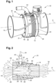
- a Coanda effect flow amplifier 10 comprises an amplifier body 12 defining a main air circulation duct 14 extending along a circulation axis A.
- the main duct 14 has for example a length of several meters, and the flow amplifier 10 is placed more than one meter from an inlet and an outlet of this main duct 14.
- the flow amplifier 10 also comprises an upstream connection 16 and a downstream connection 18 connected respectively to a first 34 and a second 36 end of the amplifier body 12.
- the first 34 and second 36 ends are arranged opposite each other along the circulation axis A.
- the upstream 16 and downstream 18 connections are configured to connect the flow amplifier 10 to air ducts.
- these air ducts are standard.
- a standard duct has an internal diameter of 200 mm for an application to pollen conveyance.
- the upstream 16 and downstream 18 connectors have a conical section in a plane perpendicular to the circulation axis A.
- the upstream 16 and downstream 18 connectors each comprise a proximal end intended to be fixed to the amplifier body 12 and a distal end intended to be fixed to a standard air duct.
- the smallest section of the upstream 16 and downstream 18 connectors is arranged at their proximal end intended to be fixed to the amplifier body 12.
- the diameter of the main duct 14 is thus smaller than the diameters of the air ducts to which the upstream 16 and downstream 18 connectors are intended to be connected.
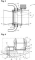
- the amplifier body 12 comprises a main body 38 forming within it the main duct 14.
- the main body 38 forms a crown of annular section whose internal wall forms the main duct 14.
- the main body 38 forms an annular section around the circulation axis A.
- the amplifier body 12 also comprises an injection crown 40 arranged against the main body 38 along the circulation axis A.
- the flow amplifier 10 comprises an injection circuit 19 for driving gas inside the main conduit 14.
- This injection circuit 19 is preferably formed at least partially, more preferably completely, inside the amplifier body 12. According to a preferred embodiment, the injection circuit 19 is formed at least partially inside the main body 38.
- a blowing flow 32 is induced by the flow amplifier 10, combining a flow of driving gas 30 from the injection circuit 19 and a secondary suction flow 28.
- the primary driving gas flow 30 is annular and arranged on the periphery of the main duct 14 relative to the circulation axis A, in contact with the walls of the main duct 14.
- the secondary suction flow 28 is central relative to the circulation axis A and of lower velocity than the primary driving gas flow 30.
- the flow amplifier 10 is configured to induce from the injection circuit 19 the secondary suction flow 28 of a predetermined speed whose ratio between said secondary suction flow 28 in the main duct 14 and the primary driving gas flow 30 is greater than or equal to 10, preferably greater than or equal to 15, more preferably greater than or equal to 17.
- the ratio between said secondary suction flow 28 in the conveying channel 16 and the primary driving gas flow 30 is equal to 17
- the quantity of primary driving gas 30 is approximately equal to 6% of the blowing flow 32 downstream.
- the injected driving gas rate has a great importance on the transport of fragile particles because it increases the differential between the suction speed that one seeks to optimize and the blowing speed which must not be increased too significantly at the risk of degrading the transported particles. Energy optimization is also an expected result of matching amplification profiles to the desired transport speeds.
- the injection circuit 19 comprises a plurality of compressed engine gas supply orifices 42, at least one injection orifice 44 opening into the interior of the main conduit 14 and a distribution conduit 46 putting the plurality of supply orifices 42 into fluid communication with the injection orifice(s) 44.
- the injection circuit 19 comprises only a single injection orifice 44 when it comprises a single distribution conduit 46. More preferably, the injection circuit 19 comprises a number of injection orifices 44 equal to the number of distribution conduits 46.
- the supply ports 42 are configured to be connected to a source of compressed driving gas 24 so as to allow the injection of compressed driving gas into the distribution conduit 46 to then be injected into the main conduit 14 through the injection ports 42.
- the supply ports 42 are in particular configured to be connected to a supply pipe 43 in fluid communication with the source of compressed gas 24.
- This source of compressed gas 24 can be integrated into the flow amplifier 10 or connected to it.
- the source of compressed gas 24 can be in the form of a compressor connected to a gas tank to compress it and inject it into the injection circuit 19. This gas is preferably ambient air.
- the feed orifices 42 are formed on an outer wall of the main body 38.
- the feed orifices 42 are preferably oriented radially to the circulation axis A to avoid any swirl phenomenon inside the injection circuit 19 as well as in the main duct 14.
- a tangential orientation of the feed orifices 42 would in fact tend to generate turbulence and swirls which would harm the uniformity and stability of the engine gas flow. As indicated above, this turbulence could harm the integrity of the fragile materials transported.
- the supply orifices 42 are formed around the circulation axis A.
- the supply orifices 42 are equally distributed around the circulation axis A on the outer wall of the main body 38 so as to distribute the flow of engine gas in the distribution duct 46. “equally distributed” means that the angular sector separating two adjacent feed orifices 42 is equal to 360° divided by the total number of feed orifices 42. Thus, if the main body 38 comprises two feed orifices 42, these are separated by an angle of 180°.
- the main body 38 may comprise at least three, at least four or even at least five feed orifices 42.
- the feed ports 42 are preferably misaligned with respect to one or more of the injection ports 44 so as to prohibit the supply of motive gas from a feed port 42 to an injection port in a continuous rectilinear path.
- a feed orifice 42 is not positioned opposite an injection orifice 44 to avoid direct access of the gas from the feed orifice 42 to the injection orifice 44.
- the feed orifices 42 and the at least one injection orifice 44 are preferably offset along the circulation axis A or angularly offset around the circulation axis A. Therefore, the distribution duct 46 forms a deflection wall facing each of the feed orifices 42. The flow of engine gas thus encounters this deflection wall as soon as it leaves a feed orifice and stabilizes in the distribution duct 46 before being injected through one or more injection orifices 44.
- the distribution conduit 46 extends at least partially along the circulation axis A.
- the supply orifices 42 and the at least one injection orifice 44 are offset along the circulation axis A so as to extend in planes perpendicular to the circulation axis A which are distinct from each other.
- the distribution duct 46 preferably forms an annular distribution cavity extending along and around the circulation axis A.
- the injection orifice 44 is preferably made in the form of a slot 71 extending at least partially around the circulation axis A.
- the slot preferably extends along an angular sector around the circulation axis A. More preferably, the slot 71 is circular and forms an annular orifice extending around the circulation axis A.
- the engine gas is injected through the slot in the form of an annular air blade around the circulation axis. circulation A, on the periphery of the main conduit 14.
- the slot 71 can be continuous all around the circulation axis A. Alternatively, the slot 71 can be produced discontinuously by a plurality of openings or portions of slots to thus form a plurality of injection orifices 44.
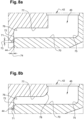
- the slot 71 is of a radial dimension relative to the axis A, such that it is possible to determine both a radial height 73 of this slot, as well as an axial width 74 of the slot along the axis A.
- the axial height of the slot 71 which opens through the injection orifice 44 corresponds to the height where the slot has the same axial width 74.
- the slot is higher radially than that of the embodiments of the Figures 8a and 8b .
- the radial height 73 of this slot 71 is limited by the presence of a connection radius 72 defined between an edge of the slot and a deflection wall 70.
- This deflection wall 70 faces each of the supply orifices 42, it is adjacent to the slot 71.
- This connection radius is for example of the order of 0.5 to 3 mm, advantageously between 1 and 2 mm.
- edge fillets and connecting radii may be provided in the distribution duct 46.
- an edge fillet 75 may be provided, adjacent to the deflection wall 70, and opposite the supply orifice 42.
- Another edge fillet 76 may be made in the wall 77 of the amplifier body 12 which is opposite the slot 71, the wall 77 and the deflection wall 70 together defining at least one section of the distribution duct 46.
- Another connecting fillet 78, Figure 8b may also be provided to soften the junction between the section defined between the walls 77 and 70, and an adjacent and transverse section in communication with the supply orifice(s).
- the edge fillets 75, 76 and/or connection 78 may be between 1 and 5 mm, preferably of the order of 3 mm.
- connection fillets and edge fillets further improves the speed performance, and therefore the flow rate of pollen collected and distributed in the same operation.
- the cross-section of the slot along the circulation axis A may be constant over the entire circumference of the main duct 14 to induce an identical air flow rate over the entire perimeter of the flow amplifier 10.
- the cross-section of the slot may be symmetrical around the circulation axis A.
- the cross-section of the slot may be variable around the circulation axis A to induce a secondary gas flow having a speed varying around the circulation axis A.
- the cross-section of the slot may thus be asymmetrical. This variation in the speed of the secondary gas flow is particularly advantageous for limiting the natural propensity of the pollen to sediment under the effect of gravity and therefore improving the maintenance of the pollen in suspension.
- the cross-section of the slot is preferably larger in its upper part than in its lower part.
- the slot comprises an upper portion having a cross-section greater than the cross-section of a lower portion arranged opposite the upper portion. This variable configuration of the slot section makes it possible to induce a more intense depression at the level of the upper portion.
- the main body 38 further comprises an amplification profile 48 at least partially delimiting the injection orifice 44.
- the amplification profile 48 forms a convex surface configured to induce a Coanda effect on the flow of compressed engine gas 30 injected through said injection orifice 44.
- the amplification profile 48 is arranged downstream in contact with the injection orifice 44 relative to the direction of movement of the gases and materials conveyed in the main conduit 14.
- the amplification profile 48 can be obtained by a curved surface so as to optimize the Coanda effect.
- the amplification profile 48 can be obtained by a plurality of rectilinear segments to facilitate its manufacture.
- the amplification profile 48 when viewed in cross-section, preferably corresponds to a portion of a "NACA" profile used in aircraft construction, particularly the upper half of the "NACA" profile.
- the amplification profile 48 preferably comprises a leading edge arranged at the injection orifice 44, an extrados and a trailing edge towards the second end 36 of the main body 38.
- the amplification profile 48 may correspond to an upper half of a “NACA0030” profile comprising a camber of the reference line (from the leading edge to the trailing edge) of 0 degrees, a camber position of 0% and a profile thickness of 30% of the chord, i.e. of the distance between the leading edge and the trailing edge.
- the Coanda effect is the property of a gas or liquid flow to follow an adjacent curved contour such as the amplification profile 48 without detaching from it.
- the primary driving air flow adheres to the curved surface in the form of a thin layer of high-velocity air which is accompanied by a depression zone thus inducing the entrainment of ambient air at a very high multiplication rate.
- the amplification profile 48 is configured so as to persist the Coanda effect over the greatest possible length in order to maximize the total surface area of high-velocity primary air flow with the corollary of the entrainment of secondary air at a very high rate, explaining the flow amplifier nature of such a device.
- the injection orifice 44 is delimited by two side walls respectively formed by the main body 38 and the injection crown 40.
- the injection orifice is formed by a space provided between the main body 38 and the injection crown 40.
- the distribution conduit 46 opens at this side wall of the main body 38.
- the injection crown 40 is shaped so as to close the end opening into the distribution conduit 46 when the injection crown 40 is arranged against the main body 38.
- One or both of the main body 38 and the injection crown 40 are shaped to maintain a space corresponding to the width of the injection orifice 44 along the circulation axis A when they are brought into contact with each other.
- the flow amplifier 10 preferably comprises means for adjusting the passage section of the injection orifice 44, or at least a portion of the plurality of injection orifices 44, so as to regulate the flow of engine gas passing through said injection orifice(s) 44.
- the adjustment means are configured to adjust the distance between the injection ring 40 and the main body 38 so as to vary the passage section of the engine gas of said injection orifice 44 or of at least one of the injection orifices 44.
- the injection ring 40 is thus movable relative to the main body 38 around at least one axis transverse to the circulation axis A of the main conduit 14.
- the adjustment means are for example configured to adjust the angle of inclination of the injection ring 40 relative to said at least one transverse axis so as to vary the passage section of engine gas of the injection orifice(s) 44 asymmetrically.
- the rotation of the injection ring 40 varies the distance between the main body 38 and the injection ring 40 over an angular sector of the injection orifice 44 or of the plurality of injection orifices 44.
- This variation in distance causes a variation in the passage section of the driving gas through this angular sector and thus makes it possible to vary the flow rate through this angular sector.
- the asymmetry induced by the angular position of the injection ring 40 thus makes it possible to obtain an asymmetrical flow rate around the circulation axis A. It is thus possible to increase the flow rate of driving gas in the upper part of the flow amplifier 10 to compensate for the effect of gravity on the conveyed materials so as to limit any contact between the fragile materials and the walls of the main conduit 14.
- the asymmetry generated by the injection ring 40 is achieved by moving the ring around a substantially horizontal axis.
- This asymmetry lateral could for example make it possible to deport the transported particles towards one side of the main conduit 14 to avoid an obstacle or anticipate a turn or a bifurcation of this conduit downstream of the flow amplifier 10 in order to limit the risks of collision.
- the adjustment means allowing the displacement of the injection crown 40 comprise for example a plurality of adjustment screws 50 bearing on the main body 38 to adjust the gap between the injection crown 40 and the main body 38. These adjustment screws 50 are screwed into the injection crown 40.
- the injection crown 40 is kept blocked between the flanges 51 and the main body 38 by means of screws.
- the asymmetrical extension and bearing of the adjustment screws 50 between several angular sectors of the injection crown 40 makes it possible to asymmetrically vary the distance separating the injection crown 40 from the main body 38.
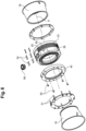
- the injection circuit 19 comprises a plurality of distribution lines independent of each other up to the injection of the driving gas inside the main conduit 14.
- the flow amplifier 10 comprises a plurality of distribution conduits 46 independent of each other.
- the flow amplifier 10 also comprises a plurality of injection orifices 44. Each supply orifice 42 and each injection orifice 44 belongs to a distribution line so that they are in fluid communication with only one distribution conduit.
- independent distribution lines make it possible to form independent engine gas flows. It is thus possible to provide engine gas flows having different characteristics, such as a different gas pressure or type of engine gas. It could indeed be envisaged to mix a single engine gas flow with an additive to provide specific characteristics at an angular sector of the main duct 14. It is also possible to provide gas flows having different pressures inducing different injection flow rates around the circulation axis A. These separate distribution lines also allow the installation of measuring devices, for example of the gas pressure, or safety devices.
- the independent distribution conduits 46 may be formed by inserting partition elements 52 inside an annular cavity.
- the distribution conduits 46 are thus portions of an annular cavity.
- These partition elements 52 extend along the circulation axis A so as to define distribution conduits 46 extending along the circulation axis A.
- the partition elements 52 can be shaped to separate the plurality of injection orifices 44 into angular sectors corresponding to the different distribution conduits 46.
- the partition elements 52 are preferably arranged inside this annular cavity so as to segment the annular cavity into angular sectors communicating at one end with a supply orifice 42 and at an opposite end with one or more injection orifices 44.
- the flow amplifier 10 preferably comprises as many supply orifices 42 as distribution conduits 46. Thus, each supply orifice 42 is preferably in fluid communication with a single distribution conduit 46.
- the partition elements 52 are for example cylinders, for example made of elastic material, arranged between the concentric walls forming the annular cavity. These cylinders are preferably housed inside housings provided in the walls of the annular cavity.
- the partition elements 52 preferably extend beyond the side wall of the main body 38 so as to induce axial and radial compression of said partition elements 52 in order to perfect the seal between distribution lines.
- the distribution lines can be distributed around the circulation axis to define angular sectors around the circulation axis A so as to be able to compensate for gravity or to deport the conveyed particles towards a portion of the main conduit 14 in order to anticipate for example a change of direction or a bifurcation.
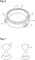
- the main body 38 may also include external reliefs intended to optimize the thermal stability of the flow amplifier 10 making it possible to prevent the formation of condensates inside the main duct 14 and in particular at the injection orifices 44 of the primary driving gas which induces an endothermic reaction by the partial expansion of the compressed gas.
- the presence of condensates on excessively cooled walls is in fact very detrimental to the conveyance of fragile materials, such as pollen. These condensates could soil the inside of the main duct 14 and cause adhesions or agglutinations of pollen so that the reproductive potential of the pollen would be reduced.
- These reliefs can be produced in the form of fins 53 provided on the outer wall of the main body 38. These reliefs or fins 53 make it possible to increase the heat exchange surfaces with the ambient air so as to prevent the appearance of condensates following the expansion of the primary engine gases.
- the flow amplifier 10 is preferably made of cast aluminum, the good thermal conductivity of which makes it possible to avoid cold spots that generate condensation.
- the flow amplifier 10 is made of a material having a thermal conductivity equal to or greater than 150 W.m-1.K-1.
- the flow amplifier 10 may also comprise means for varying the gas flow rate through the injection circuit 19. These means for varying the gas flow rate may be configured to vary the pressure of the engine gas inside the distribution lines or to vary the gas passage section at the supply orifices 42.
- This second alternative is for example illustrated in figures 4 , 6 And 7 in which the means for varying the gas flow rate comprise at least one reducing element of section 54 arranged across a supply orifice 42.
- This reducing element of section 54 has a side wall intended to obstruct the flow of engine gas passing through the supply orifice 42.
- This side wall of the reducing element of section 54 is calibrated so that the remaining passage section available for the passage of the engine gas is known.
- This section reducing element 54 is removably integrated into the supply orifice 42 to allow the pressure drop experienced by the engine gas and therefore its circulation flow rate through the supply orifice 42 to be chosen.
- the flow amplifier 10 belongs to a flow amplification kit comprising the flow amplifier 10 and a set of section reducing elements 54 having calibrated and different obstruction sections. The user can thus choose to put section reducing elements 54 of different calibrations through the supply orifices 42 so as to obtain different flow rates in the distribution lines.
- the section reducing element 54 may be in the form of a butterfly comprising a central portion and two angular sectors extending in opposite directions from this central portion.
- the angular dimension 56 of each of the angular sectors is then predetermined to correspond to a certain level of section reduction.
- the section reducing element 54 arranged on the left on the Figure 7 has an angular dimension 56 equal to 60°.
- the reducing element of section 54 arranged on the right on the Figure 7 has an angular dimension 56 equal to 90°.
- the main body 38 may also comprise at least one flat bearing surface 60 formed on its outer wall.
- This bearing surface 60 allows the flow amplifier 10 to be integrated into an aunterlic device.
- a non-through bore 62 may thus be provided near or on this bearing surface 60 to fix the flow amplifier to a structure.
- This bearing surface 60 makes it possible to avoid the use of interface parts which would weigh down the aunterlic device.
- the bearing surface 60 also allows better electrical continuity with the structure so as to evacuate the static electricity generated by the triboelectric friction of the conveyed materials.
Landscapes
- Engineering & Computer Science (AREA)
- Physics & Mathematics (AREA)
- Fluid Mechanics (AREA)
- Mechanical Engineering (AREA)
- General Engineering & Computer Science (AREA)
- Life Sciences & Earth Sciences (AREA)
- General Health & Medical Sciences (AREA)
- Genetics & Genomics (AREA)
- Health & Medical Sciences (AREA)
- Botany (AREA)
- Developmental Biology & Embryology (AREA)
- Environmental Sciences (AREA)
- Jet Pumps And Other Pumps (AREA)
Claims (15)
- Coanda-Effekt-Durchflussverstärker (10) zum Induzieren eines verstärkten Gasstroms, umfassend:- eine Hauptleitung (14) zur Zirkulation von Luft,- mindestens eine Einspritzöffnung (44), die in der Hauptleitung (14) mündet,- eine Vielzahl von Öffnungen (42) zur Zuführung von komprimiertem Treibgas, von denen jede dazu konfiguriert ist, mit einer Quelle (24) von komprimiertem Treibgas verbunden zu sein, um der mindestens einen Einspritzöffnung (44) komprimiertes Treibgas zuzuführen,- mindestens eine Verteilungsleitung (46), die die Vielzahl von Zuführöffnungen (42) mit der mindestens einen Einspritzöffnung (44) verbindet,- ein Verstärkungsprofil (48), das die mindestens eine Einspritzöffnung (44) mindestens teilweise abgrenzt und eine konvexe Oberfläche bildet, die dazu konfiguriert ist, an einem komprimierten Treibgasstrom, der durch die mindestens eine Einspritzöffnung (44) eingespritzt wird, einen Coanda-Effekt zu induzieren,- wobei sich die Hauptleitung zur Zirkulation von Luft entlang einer Zirkulationsachse (A) erstreckt, wobei die mindestens eine Verteilungsleitung einen ringförmigen Verteilungshohlraum bildet, der sich entlang der und um die Zirkulationsachse erstreckt, wobei die mindestens eine Einspritzöffnung einen Spalt bildet, der sich mindestens teilweise um die Zirkulationsachse erstreckt, und- wobei eine radiale Abmessung des Spalts durch das Vorhandensein eines Übergangsradius (71), der durch eine Ablenkwand (70), die jeder der Zuführöffnungen gegenüberliegt, bereitgestellt wird, begrenzt wird, wobei diese Ablenkwand an den Spalt, der an der Einspritzöffnung (44) mündet, angrenzt.
- Durchflussverstärker nach Anspruch 1, wobei die mindestens eine Einspritzöffnung durch einen ringförmigen Einspritzhohlraum gebildet ist, der sich um die Zirkulationsachse und in Bezug auf diese Zirkulationsachse radial erstreckt.
- Durchflussverstärker nach einem der Ansprüche 1 oder 2, wobei die Zuführöffnungen quer zu der Zirkulationsachse eingerichtet sind, wobei der Durchflussverstärker ferner mindestens eine Ablenkwand (70) beinhaltet, die jeder der Zuführöffnungen gegenüberliegt.
- Durchflussverstärker nach einem der vorhergehenden Ansprüche, beinhaltend eine Vielzahl von Verteilungsleitungen, die untereinander unabhängig sind, und eine Vielzahl von Einspritzöffnungen (44), wobei sich jede Verteilungsleitung (46) zwischen mindestens einer der Vielzahl von Zuführöffnungen (42) und mindestens einer der Vielzahl von Einspritzöffnungen (44) erstreckt, um verschiedene komprimierte Treibgasströme durch die Vielzahl von Einspritzöffnungen (44) einspritzen zu können.
- Durchflussverstärker nach Anspruch 3 in Kombination mit Anspruch 2, wobei die Vielzahl von Verteilungsleitungen durch den ringförmigen Verteilungshohlraum gebildet ist, wobei der Durchflussverstärker ferner mindestens zwei Trennwandelemente (52) beinhaltet, die es gestatten, den Verteilungshohlraum zu unterteilen, um mindestens zwei unabhängige Verteilungsleitungen zu bilden.
- Durchflussverstärker nach einem der vorhergehenden Ansprüche, ferner beinhaltend Mittel zum Einstellen eines Durchgangsquerschnitts des Treibgases der mindestens einen Einspritzöffnung, um den Treibgasdurchfluss, der durch die mindestens eine Einspritzöffnung hindurchgeht, zu regulieren.
- Durchflussverstärker nach Anspruch 3 in Kombination mit dem vorhergehenden Anspruch, wobei die Einstellmittel dazu konfiguriert sind, den Treibgasdurchgangsquerschnitt von mindestens zwei Einspritzöffnungen (44), die mit unabhängigen Verteilungsleitungen kommunizieren, gesondert einzustellen, um durch die mindestens zwei Öffnungen komprimierte Treibgasströme mit unterschiedlichen Durchflüssen einspritzen zu können.
- Durchflussverstärker nach dem vorhergehenden Anspruch, wobei die Vielzahl von Einspritzöffnungen mindestens eine erste und mindestens eine zweite Einspritzöffnung beinhaltet, die dazu bestimmt sind, jeweils im unteren Teil und im oberen Teil der Hauptleitung zur Zirkulation von Luft angeordnet zu sein, um im unteren und oberen Teil einen unterschiedlichen verstärkten Luftdurchfluss induzieren zu können.
- Durchflussverstärker nach dem vorhergehenden Anspruch, wobei die Einstellmittel dazu konfiguriert sind, den Treibgasdurchgangsquerschnitt von mindestens vier Einspritzöffnungen, die mit unabhängigen Verteilungsleitungen kommunizieren, gesondert einzustellen, wobei die Vielzahl von Einspritzöffnungen ferner mindestens eine dritte und mindestens eine vierte Einspritzöffnung beinhaltet, die dazu bestimmt sind, jeweils an gegenüberliegenden seitlichen Teilen der Hauptleitung zur Zirkulation von Luft angeordnet zu sein.
- Durchflussverstärker nach einem der vorhergehenden Ansprüche, beinhaltend:- einen Körper (38), in dem die Hauptleitung zur Zirkulation von Luft, die Vielzahl von Zuführöffnungen, die mindestens eine Verteilungsleitung, das Verstärkungsprofil und ein erster Abschnitt der mindestens einen Einspritzöffnung gebildet sind,- einen Einspritzkranz (40), der einen zweiten Abschnitt der mindestens einen Einspritzöffnung bildet, wobei der Einspritzkranz dazu konfiguriert ist, gegenüber dem Körper angeordnet zu sein, wobei sich der erste und der zweite Abschnitt der mindestens einen Einspritzöffnung gegenüberliegen, wobei der Abstand, der den ersten und den zweiten Abschnitt der mindestens einen Einspritzöffnung trennt, einen Durchgangsquerschnitt von Treibgas durch die mindestens eine Einspritzöffnung definiert.
- Durchflussverstärker nach dem vorhergehenden Anspruch in Kombination mit Anspruch 5, wobei die Einstellmittel dazu konfiguriert sind, den Abstand zwischen dem Einspritzkranz und dem Körper einzustellen, um den Durchgangsquerschnitt des Treibgases der mindestens einen Einspritzöffnung variieren zu lassen.
- Durchflussverstärker nach dem vorhergehenden Anspruch, wobei der Kranz in Bezug auf den Körper um mindestens eine Achse, die zu einer Zirkulationsachse der Hauptzirkulationsleitung quer verläuft, beweglich ist, wobei die Einstellmittel dazu konfiguriert sind, den Neigungswinkel des Kranzes in Bezug auf die mindestens eine Querachse einzustellen, um den Treibgasdurchgangsquerschnitt der mindestens einen Einspritzöffnung auf asymmetrische Weise variieren zu lassen.
- Lufteinrichtung zur Bestäubung mindestens einer Empfängerpflanze mit Hilfe von Pollen, der an einer Spenderpflanze gewonnen wird, beinhaltend:- ein Organ zum Gewinnen des Pollens von der mindestens einen Spenderpflanze,- mindestens ein Organ zur Verbreitung des Pollens auf mindestens einer Empfängerpflanze,- einen Kanal zum Befördern des gewonnenen Pollens von dem Gewinnungsorgan zu dem oder den Verbreitungsorganen und- mindesten einen Durchflussverstärker nach einem der vorhergehenden Ansprüche.
- Verwendung eines Durchflussverstärkers nach einem der Ansprüche 1 bis 12 zur Verstärkung eines Luftstroms, der Partikel beinhaltet, die eine vorbestimmte Sedimentationsgeschwindigkeit aufweisen, wobei der Coanda-Effekt-Durchflussverstärker innerhalb der Hauptzirkulationsleitung einen Luftstrom induziert, dessen Geschwindigkeit größer als die vorbestimmte Sedimentationsgeschwindigkeit ist.
- Verwendung nach Anspruch 14, wobei die Geschwindigkeit des innerhalb der Hauptzirkulationsleitung induzierten Luftstroms gleich oder kleiner als 10m.s-1, vorzugsweise gleich oder kleiner als 5m.s-1, ist.
Applications Claiming Priority (2)
| Application Number | Priority Date | Filing Date | Title |
|---|---|---|---|
| FR2008012A FR3113112B1 (fr) | 2020-07-29 | 2020-07-29 | Amplificateur de débit à effet Coanda et dispositif aéraulique comprenant un tel amplificateur de débit |
| PCT/FR2021/051400 WO2022023663A1 (fr) | 2020-07-29 | 2021-07-27 | Amplificateur de debit a effet coanda et dispositif aeraulique comprenant un tel amplificateur de debit |
Publications (3)
| Publication Number | Publication Date |
|---|---|
| EP4188076A1 EP4188076A1 (de) | 2023-06-07 |
| EP4188076C0 EP4188076C0 (de) | 2025-06-25 |
| EP4188076B1 true EP4188076B1 (de) | 2025-06-25 |
Family
ID=72885792
Family Applications (1)
| Application Number | Title | Priority Date | Filing Date |
|---|---|---|---|
| EP21756020.0A Active EP4188076B1 (de) | 2020-07-29 | 2021-07-27 | Coanda-effekt-durchflussverstärker und lufteinrichtung beinhaltend einen solchen durchflussverstärker |
Country Status (11)
| Country | Link |
|---|---|
| US (1) | US12193379B2 (de) |
| EP (1) | EP4188076B1 (de) |
| CN (1) | CN116133518A (de) |
| AR (1) | AR123077A1 (de) |
| BR (1) | BR112023001365A2 (de) |
| CA (1) | CA3185974A1 (de) |
| FR (1) | FR3113112B1 (de) |
| MX (1) | MX2023001174A (de) |
| PH (1) | PH12023550166A1 (de) |
| WO (1) | WO2022023663A1 (de) |
| ZA (1) | ZA202300919B (de) |
Families Citing this family (1)
| Publication number | Priority date | Publication date | Assignee | Title |
|---|---|---|---|---|
| CN119233752A (zh) | 2022-05-20 | 2024-12-31 | 巴斯夫欧洲公司 | 用于农用田地中的作物植株的花粉分配装置、对应用途和操作方法 |
Family Cites Families (4)
| Publication number | Priority date | Publication date | Assignee | Title |
|---|---|---|---|---|
| GB8516264D0 (en) * | 1985-06-27 | 1985-07-31 | Coleman J D | Compressed air powered suction unit |
| GB2234782B (en) * | 1989-06-17 | 1993-07-14 | James David Coleman | Variable throat geometry coanda ejectors |
| DE102009047089B4 (de) * | 2009-11-24 | 2012-01-26 | J. Schmalz Gmbh | Druckluftbetriebener Unterdruckerzeuger |
| FR3078859B1 (fr) * | 2018-03-14 | 2020-03-13 | Syngenta France Sas | Dispositif aeraulique a effet coanda pour la pollinisation d'une plante receveuse a partir du pollen capte d'une plante donneuse |
-
2020
- 2020-07-29 FR FR2008012A patent/FR3113112B1/fr active Active
-
2021
- 2021-07-27 PH PH1/2023/550166A patent/PH12023550166A1/en unknown
- 2021-07-27 US US18/016,341 patent/US12193379B2/en active Active
- 2021-07-27 BR BR112023001365A patent/BR112023001365A2/pt unknown
- 2021-07-27 CN CN202180060405.2A patent/CN116133518A/zh active Pending
- 2021-07-27 WO PCT/FR2021/051400 patent/WO2022023663A1/fr not_active Ceased
- 2021-07-27 CA CA3185974A patent/CA3185974A1/en active Pending
- 2021-07-27 EP EP21756020.0A patent/EP4188076B1/de active Active
- 2021-07-27 MX MX2023001174A patent/MX2023001174A/es unknown
- 2021-07-29 AR ARP210102106A patent/AR123077A1/es unknown
-
2023
- 2023-01-20 ZA ZA2023/00919A patent/ZA202300919B/en unknown
Also Published As
| Publication number | Publication date |
|---|---|
| ZA202300919B (en) | 2024-05-30 |
| US12193379B2 (en) | 2025-01-14 |
| MX2023001174A (es) | 2023-02-22 |
| AR123077A1 (es) | 2022-10-26 |
| BR112023001365A2 (pt) | 2023-02-14 |
| WO2022023663A1 (fr) | 2022-02-03 |
| CA3185974A1 (en) | 2022-02-03 |
| PH12023550166A1 (en) | 2024-03-18 |
| EP4188076C0 (de) | 2025-06-25 |
| FR3113112A1 (fr) | 2022-02-04 |
| EP4188076A1 (de) | 2023-06-07 |
| CN116133518A (zh) | 2023-05-16 |
| US20230270066A1 (en) | 2023-08-31 |
| FR3113112B1 (fr) | 2024-08-16 |
Similar Documents
| Publication | Publication Date | Title |
|---|---|---|
| CA2416150C (fr) | Diffuseur pour moteur a turbine a gaz terrestre ou aeronautique | |
| CA2933123C (fr) | Piece de turbomachine a surface non-axisymetrique definissant une pluralite d'ailettes | |
| CA3091882A1 (fr) | Dispositif aeraulique a effet coanda pour la pollinisation d'une plante receveuse a partir du pollen capte d'une plante donneuse | |
| FR2556054A1 (fr) | Diffuseur pour compresseur centrifuge | |
| EP4188076B1 (de) | Coanda-effekt-durchflussverstärker und lufteinrichtung beinhaltend einen solchen durchflussverstärker | |
| FR2929334A1 (fr) | Dispositif de reduction du bruit genere par reacteur d'aeronef a conduits de fluide coudes | |
| EP2430314B1 (de) | Zentrifugalpumpe mit doppeltem auslass | |
| FR2697287A1 (fr) | Diffuseur d'échappement de turbine à gaz. | |
| CA2754419C (fr) | Chambre de combustion de turbomachine comprenant des moyens ameliores d'alimentation en air | |
| FR3058460A1 (fr) | Ensemble de raccordement pour le refroidissement d'une turbine de turbomachine | |
| EP1746348B1 (de) | Turbogruppe mit einer Umfangsverteilung der Verbrennungsluft | |
| FR3016027A1 (fr) | Echangeur thermique comprenant une grille | |
| EP3011185A1 (de) | Zentrifugalrotor | |
| WO2019239074A1 (fr) | Aube de turbine comprenant un systeme passif de reduction des phenomenes tourbillonaires dans un flux d'air qui la parcourt | |
| BE1005290A3 (fr) | Ameliorations a un compresseur du type regeneratif a chambre toroidale. | |
| EP3274578A1 (de) | Vorrichtung mit gittern zum ausstossen von mikrostrahlen zur minderung des strahllärms eines turbinenmotors | |
| FR3087855A1 (fr) | Un turbocompresseur centrifuge ayant un trajet de flux de gaz comportant une chambre de detente | |
| FR3117548A1 (fr) | Dispositif d’entrainement d’un flux d’air principal pour une turbomachine d’aeronef | |
| WO2022243622A1 (fr) | Dispositif d'entrainement d'un flux d'air principal pour une turbomachine d'aeronef | |
| EP0808425A1 (de) | Verfahren zum konditionieren einer flüssigkeitsströmung und behandlungsvorrichtung einer flüssigkeitsströmung | |
| FR3005109A1 (fr) | Volute a deux volumes pour turbine a gaz | |
| FR3109175A1 (fr) | Grille conique de conduit de décharge | |
| FR2581568A1 (fr) | Ventilateur exhausteur | |
| FR2666383A1 (fr) | Compresseur centrifuge. | |
| EP1500876A1 (de) | Ventilationsluftabzugvorrichtung auf Dächern oder Gebäudefassaden |
Legal Events
| Date | Code | Title | Description |
|---|---|---|---|
| STAA | Information on the status of an ep patent application or granted ep patent |
Free format text: STATUS: UNKNOWN |
|
| STAA | Information on the status of an ep patent application or granted ep patent |
Free format text: STATUS: THE INTERNATIONAL PUBLICATION HAS BEEN MADE |
|
| PUAI | Public reference made under article 153(3) epc to a published international application that has entered the european phase |
Free format text: ORIGINAL CODE: 0009012 |
|
| STAA | Information on the status of an ep patent application or granted ep patent |
Free format text: STATUS: REQUEST FOR EXAMINATION WAS MADE |
|
| 17P | Request for examination filed |
Effective date: 20221208 |
|
| AK | Designated contracting states |
Kind code of ref document: A1 Designated state(s): AL AT BE BG CH CY CZ DE DK EE ES FI FR GB GR HR HU IE IS IT LI LT LU LV MC MK MT NL NO PL PT RO RS SE SI SK SM TR |
|
| P01 | Opt-out of the competence of the unified patent court (upc) registered |
Effective date: 20230829 |
|
| DAV | Request for validation of the european patent (deleted) | ||
| DAX | Request for extension of the european patent (deleted) | ||
| STAA | Information on the status of an ep patent application or granted ep patent |
Free format text: STATUS: EXAMINATION IS IN PROGRESS |
|
| 17Q | First examination report despatched |
Effective date: 20240612 |
|
| 17Q | First examination report despatched |
Effective date: 20240626 |
|
| GRAP | Despatch of communication of intention to grant a patent |
Free format text: ORIGINAL CODE: EPIDOSNIGR1 |
|
| STAA | Information on the status of an ep patent application or granted ep patent |
Free format text: STATUS: GRANT OF PATENT IS INTENDED |
|
| INTG | Intention to grant announced |
Effective date: 20250123 |
|
| RAP3 | Party data changed (applicant data changed or rights of an application transferred) |
Owner name: ASUR PLANT BREEDING Owner name: SYNGENTA CROP PROTECTION AG Owner name: INSTITUT NATIONAL DE RECHERCHE POUR L'AGRICULTURE,L'ALIMENTATION ET L'ENVIRONNEMENT |
|
| GRAS | Grant fee paid |
Free format text: ORIGINAL CODE: EPIDOSNIGR3 |
|
| GRAA | (expected) grant |
Free format text: ORIGINAL CODE: 0009210 |
|
| STAA | Information on the status of an ep patent application or granted ep patent |
Free format text: STATUS: THE PATENT HAS BEEN GRANTED |
|
| AK | Designated contracting states |
Kind code of ref document: B1 Designated state(s): AL AT BE BG CH CY CZ DE DK EE ES FI FR GB GR HR HU IE IS IT LI LT LU LV MC MK MT NL NO PL PT RO RS SE SI SK SM TR |
|
| REG | Reference to a national code |
Ref country code: GB Ref legal event code: FG4D Free format text: NOT ENGLISH |
|
| REG | Reference to a national code |
Ref country code: CH Ref legal event code: EP |
|
| REG | Reference to a national code |
Ref country code: CH Ref legal event code: EP |
|
| REG | Reference to a national code |
Ref country code: IE Ref legal event code: FG4D Free format text: LANGUAGE OF EP DOCUMENT: FRENCH |
|
| REG | Reference to a national code |
Ref country code: DE Ref legal event code: R096 Ref document number: 602021032906 Country of ref document: DE |
|
| U01 | Request for unitary effect filed |
Effective date: 20250711 |
|
| U07 | Unitary effect registered |
Designated state(s): AT BE BG DE DK EE FI FR IT LT LU LV MT NL PT RO SE SI Effective date: 20250717 |
|
| U20 | Renewal fee for the european patent with unitary effect paid |
Year of fee payment: 5 Effective date: 20250827 |
|
| PG25 | Lapsed in a contracting state [announced via postgrant information from national office to epo] |
Ref country code: GR Free format text: LAPSE BECAUSE OF FAILURE TO SUBMIT A TRANSLATION OF THE DESCRIPTION OR TO PAY THE FEE WITHIN THE PRESCRIBED TIME-LIMIT Effective date: 20250926 Ref country code: NO Free format text: LAPSE BECAUSE OF FAILURE TO SUBMIT A TRANSLATION OF THE DESCRIPTION OR TO PAY THE FEE WITHIN THE PRESCRIBED TIME-LIMIT Effective date: 20250925 |
|
| PGFP | Annual fee paid to national office [announced via postgrant information from national office to epo] |
Ref country code: GB Payment date: 20250725 Year of fee payment: 5 |
|
| PG25 | Lapsed in a contracting state [announced via postgrant information from national office to epo] |
Ref country code: HR Free format text: LAPSE BECAUSE OF FAILURE TO SUBMIT A TRANSLATION OF THE DESCRIPTION OR TO PAY THE FEE WITHIN THE PRESCRIBED TIME-LIMIT Effective date: 20250625 |
|
| PG25 | Lapsed in a contracting state [announced via postgrant information from national office to epo] |
Ref country code: RS Free format text: LAPSE BECAUSE OF FAILURE TO SUBMIT A TRANSLATION OF THE DESCRIPTION OR TO PAY THE FEE WITHIN THE PRESCRIBED TIME-LIMIT Effective date: 20250925 |
|
| PG25 | Lapsed in a contracting state [announced via postgrant information from national office to epo] |
Ref country code: IS Free format text: LAPSE BECAUSE OF FAILURE TO SUBMIT A TRANSLATION OF THE DESCRIPTION OR TO PAY THE FEE WITHIN THE PRESCRIBED TIME-LIMIT Effective date: 20251025 |