EP1500876A1 - Ventilationsluftabzugvorrichtung auf Dächern oder Gebäudefassaden - Google Patents
Ventilationsluftabzugvorrichtung auf Dächern oder Gebäudefassaden Download PDFInfo
- Publication number
- EP1500876A1 EP1500876A1 EP03405555A EP03405555A EP1500876A1 EP 1500876 A1 EP1500876 A1 EP 1500876A1 EP 03405555 A EP03405555 A EP 03405555A EP 03405555 A EP03405555 A EP 03405555A EP 1500876 A1 EP1500876 A1 EP 1500876A1
- Authority
- EP
- European Patent Office
- Prior art keywords
- section
- cross
- flow
- chamber
- speed
- Prior art date
- Legal status (The legal status is an assumption and is not a legal conclusion. Google has not performed a legal analysis and makes no representation as to the accuracy of the status listed.)
- Withdrawn
Links
- 238000009423 ventilation Methods 0.000 title 1
- 239000012530 fluid Substances 0.000 claims abstract description 26
- 239000007788 liquid Substances 0.000 claims abstract description 10
- 230000001133 acceleration Effects 0.000 claims abstract description 4
- 230000004907 flux Effects 0.000 claims description 22
- 238000007599 discharging Methods 0.000 claims description 2
- 230000005484 gravity Effects 0.000 claims description 2
- 238000010276 construction Methods 0.000 description 3
- 235000021183 entrée Nutrition 0.000 description 2
- 238000004519 manufacturing process Methods 0.000 description 2
- 239000002184 metal Substances 0.000 description 2
- 238000000034 method Methods 0.000 description 2
- XLYOFNOQVPJJNP-UHFFFAOYSA-N water Substances O XLYOFNOQVPJJNP-UHFFFAOYSA-N 0.000 description 2
- 235000001674 Agaricus brunnescens Nutrition 0.000 description 1
- 240000008042 Zea mays Species 0.000 description 1
- 239000011810 insulating material Substances 0.000 description 1
- 239000000463 material Substances 0.000 description 1
- 238000000926 separation method Methods 0.000 description 1
- 239000007787 solid Substances 0.000 description 1
- 238000011144 upstream manufacturing Methods 0.000 description 1
Images
Classifications
-
- F—MECHANICAL ENGINEERING; LIGHTING; HEATING; WEAPONS; BLASTING
- F23—COMBUSTION APPARATUS; COMBUSTION PROCESSES
- F23L—SUPPLYING AIR OR NON-COMBUSTIBLE LIQUIDS OR GASES TO COMBUSTION APPARATUS IN GENERAL ; VALVES OR DAMPERS SPECIALLY ADAPTED FOR CONTROLLING AIR SUPPLY OR DRAUGHT IN COMBUSTION APPARATUS; INDUCING DRAUGHT IN COMBUSTION APPARATUS; TOPS FOR CHIMNEYS OR VENTILATING SHAFTS; TERMINALS FOR FLUES
- F23L17/00—Inducing draught; Tops for chimneys or ventilating shafts; Terminals for flues
- F23L17/02—Tops for chimneys or ventilating shafts; Terminals for flues
-
- F—MECHANICAL ENGINEERING; LIGHTING; HEATING; WEAPONS; BLASTING
- F23—COMBUSTION APPARATUS; COMBUSTION PROCESSES
- F23J—REMOVAL OR TREATMENT OF COMBUSTION PRODUCTS OR COMBUSTION RESIDUES; FLUES
- F23J13/00—Fittings for chimneys or flues
- F23J13/02—Linings; Jackets; Casings
-
- F—MECHANICAL ENGINEERING; LIGHTING; HEATING; WEAPONS; BLASTING
- F23—COMBUSTION APPARATUS; COMBUSTION PROCESSES
- F23J—REMOVAL OR TREATMENT OF COMBUSTION PRODUCTS OR COMBUSTION RESIDUES; FLUES
- F23J2900/00—Special arrangements for conducting or purifying combustion fumes; Treatment of fumes or ashes
- F23J2900/13004—Water draining devices associated with flues
Definitions
- the invention relates to a device for the evacuation towards the atmosphere of a gaseous fluid from a discharge pipe.
- the invention relates particularly to a device for the evacuation to the atmosphere of stale air extracted from premises, such as premises housing, administrative premises, industrial premises or other.
- the invention relates especially to a device intended to be fixed in protrusion with respect to an external surface, such as a roof surface, for ensure the evacuation of a flow of air with a determined speed, according to a substantially vertical direction.
- the chamber houses a element, called collection, arranged axially to collect and evacuate controlled way the rainwater that enters the room through said second opening.
- the collection element consists of a single receptacle (DE 44 19 604) or a network of a plurality of small receptacles (JP 60 129 522), it extends in general transversely to the longitudinal axis of the device on a section of extension substantially greater than the cross section of the second opening.
- the transverse dimensions of the chamber at level of said collection element are greater than the dimensions cross-sections of the chamber upstream and downstream of said collection element, compensate for the loss of section induced by the presence of this collection element.
- the wall of the chamber is relatively thin and the shape external device is very close to its inner shape.
- This type of form does not satisfy, in particular, architects who preferentially look for cylindrical shapes.
- a solution to the problem posed by the external form of known devices would consist in constituting a cylindrical dressing around the evacuation device.
- the state of the art also includes devices absolutely cylindrical, for example DE 41 19 971, constituted by a section pipe in which a spiral collecting element extends.
- a result that the invention aims to obtain is a device of the aforementioned type, which while ensuring the evacuation Vertical of a gas flow with adequate speed, has an external shape substantially, but not limitatively, cylindrical or slightly conical and, is of a comparable manufacturing cost, or even lower, to the devices of the state of the technique whose form and / or effectiveness have been criticized.
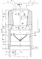
- This device 1 comprises at least one chamber 6 defined by a inner face 7 of a tubular wall 8 which, in use position has a longitudinal axis 9 substantially vertical, is intended to be crossed by the gaseous fluid 4 along its longitudinal axis 9.
- tubular wall 8 of the device 1 has a section circular cross-section and a cylindrical form of revolution, but this is not not limiting for the invention.
- the invention adapts perfectly to the construction of devices of the aforementioned type, whose cross section is polygonal, for example, square.
- the invention adapts perfectly to the construction of devices of the aforementioned type which are not absolutely cylindrical.
- the device 1 At its lower part the device 1 comprises a means 50 of connection with the evacuation pipe 5 to which it must be connected.
- this link means 50 consists of a range assembly with the end of the exhaust pipe 5 to which it must to be connected.
- the first opening 10 of the device 1 is located in the extension of this bore.
- the chamber 6 houses an element 12, called collection, situated axially for collecting and discharging in a controlled manner a liquid fluid 13, such as water of rain, entering the chamber 6, by gravity, by said second opening 11.
- a liquid fluid 13 such as water of rain
- liquid fluid 13 has been represented by a plurality circles associated with reference 13.
- this collection element 12 consists of advantageously in a hollow part of conical or hemispherical shape which turns its concavity towards the top of the device so as to collect water falling in said device 1.
- the hollow part is provided with of an evacuation pipe, for example, through the tubular wall 8 of the device 1.
- the second speed V2 substantially equal to twice the first speed V1.
- the sections can have a solid wall, as is shown, or a hollow wall, or even a hollow wall filled with a thermally and / or acoustically insulating material.
- the device 1 comprises a member 17 for guiding drops of liquid fluid 13 towards the collecting element 12, such as a flange 17 projecting from inside the second section 15.
- the section cross-section of chamber 6 is inscribed in the cross-section of the collection element 12 and centered on the latter.
- the algebraic value of the section cross-section of the second opening 11 of the device 1 is greater than the algebraic value of the cross section of the first pass controlled 141 of the flow between the second section 15 and the third section 16, but less than the algebraic value of the cross section of the first opening 10 (inlet opening) of the device 1.
- the functional characteristics of the sections thus make it possible to maintain the internal cross section of the device at a substantially less than that of the first opening and thereby make it possible obtaining the essential result targeted by the invention, namely, a device of evacuation, which while allowing to guarantee the evacuation of a gas flow with a desired speed, has an outer shape substantially, but not limitingly, cylindrical or slightly conical and, is of a cost of Comparable or less than comparable manufacture to the devices of the state of the art whose form and / or effectiveness have been criticized.
- the outer diameter is two hundred and six millimeters.
- the outer diameter is six hundred and six millimeters.
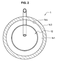
- first section 14 of the device 1 comprises, at least at the level of the connecting means 50 with the driving 5, at least one channel arranged to ensure controlled evacuation fluid 13 located on the inner cylindrical surface 144 of said first section 14, this evacuation being carried out of the device 1.
- the device 1 comprises means 50 connection with the evacuation pipe 5 to which it must be connected and this middle 50 consists of an assembly scope with the end of the pipe 5 to which it must be connected.
- connection means 50 of the device 1 with the exhaust pipe 5 to which it is to be connected consists in an assembly span by interlocking on an outer surface of the end of said discharge pipe 5 and, secondly, this scope comprises a plurality of channels each of which is constituted so as to evacuate the fluid 13 between the wall 142 of the first section 14 and the surface external of the discharge pipe 5 which receives the device 1.
- the connecting means 50 may also include a joint, but the skilled person is able to provide such an element without having to do proof of invention.
Landscapes
- Engineering & Computer Science (AREA)
- Mechanical Engineering (AREA)
- General Engineering & Computer Science (AREA)
- Chemical & Material Sciences (AREA)
- Combustion & Propulsion (AREA)
- Physical Or Chemical Processes And Apparatus (AREA)
- Separation By Low-Temperature Treatments (AREA)
- Separation Of Particles Using Liquids (AREA)
- Separating Particles In Gases By Inertia (AREA)
- Heat-Exchange Devices With Radiators And Conduit Assemblies (AREA)
- Building Environments (AREA)
Priority Applications (4)
| Application Number | Priority Date | Filing Date | Title |
|---|---|---|---|
| EP03405555A EP1500876A1 (de) | 2003-07-21 | 2003-07-21 | Ventilationsluftabzugvorrichtung auf Dächern oder Gebäudefassaden |
| AT04102198T ATE402376T1 (de) | 2003-07-21 | 2004-05-18 | Ventilationsluftabzugvorrichtung auf dächern oder gebäudefassaden |
| DE602004015204T DE602004015204D1 (de) | 2003-07-21 | 2004-05-18 | Ventilationsluftabzugvorrichtung auf Dächern oder Gebäudefassaden |
| EP04102198A EP1500877B1 (de) | 2003-07-21 | 2004-05-18 | Ventilationsluftabzugvorrichtung auf Dächern oder Gebäudefassaden |
Applications Claiming Priority (1)
| Application Number | Priority Date | Filing Date | Title |
|---|---|---|---|
| EP03405555A EP1500876A1 (de) | 2003-07-21 | 2003-07-21 | Ventilationsluftabzugvorrichtung auf Dächern oder Gebäudefassaden |
Publications (1)
| Publication Number | Publication Date |
|---|---|
| EP1500876A1 true EP1500876A1 (de) | 2005-01-26 |
Family
ID=33484082
Family Applications (2)
| Application Number | Title | Priority Date | Filing Date |
|---|---|---|---|
| EP03405555A Withdrawn EP1500876A1 (de) | 2003-07-21 | 2003-07-21 | Ventilationsluftabzugvorrichtung auf Dächern oder Gebäudefassaden |
| EP04102198A Expired - Lifetime EP1500877B1 (de) | 2003-07-21 | 2004-05-18 | Ventilationsluftabzugvorrichtung auf Dächern oder Gebäudefassaden |
Family Applications After (1)
| Application Number | Title | Priority Date | Filing Date |
|---|---|---|---|
| EP04102198A Expired - Lifetime EP1500877B1 (de) | 2003-07-21 | 2004-05-18 | Ventilationsluftabzugvorrichtung auf Dächern oder Gebäudefassaden |
Country Status (3)
| Country | Link |
|---|---|
| EP (2) | EP1500876A1 (de) |
| AT (1) | ATE402376T1 (de) |
| DE (1) | DE602004015204D1 (de) |
Citations (3)
| Publication number | Priority date | Publication date | Assignee | Title |
|---|---|---|---|---|
| GB412791A (en) * | 1933-08-28 | 1934-07-05 | Arthur Sutton | Roof ventilator |
| DE2607712A1 (de) * | 1976-02-25 | 1977-09-08 | Hans Schwarz Ohg | Abluftmischhaube |
| DE4419604A1 (de) * | 1994-06-06 | 1995-12-07 | Werner Siegle | Schornsteinanordnung mit Regenauffänger |
-
2003
- 2003-07-21 EP EP03405555A patent/EP1500876A1/de not_active Withdrawn
-
2004
- 2004-05-18 AT AT04102198T patent/ATE402376T1/de not_active IP Right Cessation
- 2004-05-18 EP EP04102198A patent/EP1500877B1/de not_active Expired - Lifetime
- 2004-05-18 DE DE602004015204T patent/DE602004015204D1/de not_active Expired - Lifetime
Patent Citations (3)
| Publication number | Priority date | Publication date | Assignee | Title |
|---|---|---|---|---|
| GB412791A (en) * | 1933-08-28 | 1934-07-05 | Arthur Sutton | Roof ventilator |
| DE2607712A1 (de) * | 1976-02-25 | 1977-09-08 | Hans Schwarz Ohg | Abluftmischhaube |
| DE4419604A1 (de) * | 1994-06-06 | 1995-12-07 | Werner Siegle | Schornsteinanordnung mit Regenauffänger |
Also Published As
| Publication number | Publication date |
|---|---|
| EP1500877A1 (de) | 2005-01-26 |
| EP1500877B1 (de) | 2008-07-23 |
| DE602004015204D1 (de) | 2008-09-04 |
| ATE402376T1 (de) | 2008-08-15 |
Similar Documents
| Publication | Publication Date | Title |
|---|---|---|
| EP0942220B1 (de) | Strömungskonditionierer für Gase führende Leitungen | |
| EP0147303B1 (de) | Mehrstufiger Impaktor mit gleichmässigem Niederschlag zur Aerosol-Probeentnahme | |
| EP2851689B1 (de) | Aerodynamische Messsonde mit Ausscheidung von Infiltrationsflüssigkeit mit Hilfe der Schwerkraft | |
| EP0641972B1 (de) | Statische, dynamische Gasabfuhreinrichtung | |
| CA1256822A (fr) | Dispositif de conditionnement de l'eau contenant ou carbonate de calcium et installation realisee avec ce dispositif | |
| EP2085488B1 (de) | Device for blowing gas onto a surface of a material in running strips | |
| FR2697287A1 (fr) | Diffuseur d'échappement de turbine à gaz. | |
| EP2919915A1 (de) | Vorrichtung zur filterung von wasser einer schwimmbeckens | |
| FR2929334A1 (fr) | Dispositif de reduction du bruit genere par reacteur d'aeronef a conduits de fluide coudes | |
| EP3244515B1 (de) | Elektromotor, der eine aussenkühlvorrichtung und eine vielzahl von kühlkreisläufen umfasst | |
| FR2474651A1 (fr) | Installation de rejet dans l'atmosphere ambiante d'un fluide gazeux sous pression a vitesse elevee | |
| EP1500877B1 (de) | Ventilationsluftabzugvorrichtung auf Dächern oder Gebäudefassaden | |
| EP0772003B1 (de) | Gerät zum Absaugen eines Gases aus einer Leitung um es abzuführen | |
| FR3066415B1 (fr) | Dispositif d'ejection pneumatique et machine de tri comportant un tel dispositif | |
| EP0184952A1 (de) | Luftregenerator mittels eines Venturis mit Sauerstoffstrahl | |
| FR2658271A1 (fr) | Dispositif pour l'aspiration et le rejet de gaz ou fumees et installation comportant une pluralite de tels dispositifs. | |
| FR3119834A1 (fr) | Systeme generateur de portance et bateau muni d’un tel systeme | |
| FR2629063A1 (fr) | Perfectionnement aux gaines de dechargement | |
| EP0082775B1 (de) | Schornsteinaufsatz für gasförmiges Fluid | |
| EP1825132B1 (de) | Element für den abgaskreislauf eines verbrennungsmotors | |
| EP3328516B1 (de) | Vorrichtung zum fangen von partikeln in einem gasstrom | |
| FR2629555A1 (fr) | Vanne numerique | |
| FR2763390A1 (fr) | Systeme de ventilation avec injection d'air supplementaire pour l'aide au tirage | |
| EP0581636B1 (de) | Stromverbesserer für eine Entspannungsstation und Messvorrichtung | |
| EP1597560A1 (de) | Probenbecher für mikrobiologische suspensionspartikel in einer atmosphäre und probennahmevorrichtung für den becher |
Legal Events
| Date | Code | Title | Description |
|---|---|---|---|
| PUAI | Public reference made under article 153(3) epc to a published international application that has entered the european phase |
Free format text: ORIGINAL CODE: 0009012 |
|
| AK | Designated contracting states |
Kind code of ref document: A1 Designated state(s): AT BE BG CH CY CZ DE DK EE ES FI FR GB GR HU IE IT LI LU MC NL PT RO SE SI SK TR |
|
| AX | Request for extension of the european patent |
Extension state: AL LT LV MK |
|
| AKX | Designation fees paid | ||
| REG | Reference to a national code |
Ref country code: DE Ref legal event code: 8566 |
|
| STAA | Information on the status of an ep patent application or granted ep patent |
Free format text: STATUS: THE APPLICATION IS DEEMED TO BE WITHDRAWN |
|
| 18D | Application deemed to be withdrawn |
Effective date: 20050727 |