EP4188047B1 - Kühlblockanordnung zur kühlung eines wärmeerzeugenden elektronischen bauteils - Google Patents
Kühlblockanordnung zur kühlung eines wärmeerzeugenden elektronischen bauteils Download PDFInfo
- Publication number
- EP4188047B1 EP4188047B1 EP22306283.7A EP22306283A EP4188047B1 EP 4188047 B1 EP4188047 B1 EP 4188047B1 EP 22306283 A EP22306283 A EP 22306283A EP 4188047 B1 EP4188047 B1 EP 4188047B1
- Authority
- EP
- European Patent Office
- Prior art keywords
- heat
- base
- cooling
- base body
- fluid conduit
- Prior art date
- Legal status (The legal status is an assumption and is not a legal conclusion. Google has not performed a legal analysis and makes no representation as to the accuracy of the status listed.)
- Active
Links
Images


Classifications
-
- H—ELECTRICITY
- H05—ELECTRIC TECHNIQUES NOT OTHERWISE PROVIDED FOR
- H05K—PRINTED CIRCUITS; CASINGS OR CONSTRUCTIONAL DETAILS OF ELECTRIC APPARATUS; MANUFACTURE OF ASSEMBLAGES OF ELECTRICAL COMPONENTS
- H05K7/00—Constructional details common to different types of electric apparatus
- H05K7/20—Modifications to facilitate cooling, ventilating, or heating
- H05K7/20218—Modifications to facilitate cooling, ventilating, or heating using a liquid coolant without phase change in electronic enclosures
- H05K7/20254—Cold plates transferring heat from heat source to coolant
-
- H—ELECTRICITY
- H05—ELECTRIC TECHNIQUES NOT OTHERWISE PROVIDED FOR
- H05K—PRINTED CIRCUITS; CASINGS OR CONSTRUCTIONAL DETAILS OF ELECTRIC APPARATUS; MANUFACTURE OF ASSEMBLAGES OF ELECTRICAL COMPONENTS
- H05K7/00—Constructional details common to different types of electric apparatus
- H05K7/20—Modifications to facilitate cooling, ventilating, or heating
- H05K7/2029—Modifications to facilitate cooling, ventilating, or heating using a liquid coolant with phase change in electronic enclosures
- H05K7/20327—Accessories for moving fluid, for connecting fluid conduits, for distributing fluid or for preventing leakage, e.g. pumps, tanks or manifolds
-
- G—PHYSICS
- G06—COMPUTING OR CALCULATING; COUNTING
- G06F—ELECTRIC DIGITAL DATA PROCESSING
- G06F1/00—Details not covered by groups G06F3/00 - G06F13/00 and G06F21/00
- G06F1/16—Constructional details or arrangements
- G06F1/20—Cooling means
-
- F—MECHANICAL ENGINEERING; LIGHTING; HEATING; WEAPONS; BLASTING
- F28—HEAT EXCHANGE IN GENERAL
- F28D—HEAT-EXCHANGE APPARATUS, NOT PROVIDED FOR IN ANOTHER SUBCLASS, IN WHICH THE HEAT-EXCHANGE MEDIA DO NOT COME INTO DIRECT CONTACT
- F28D1/00—Heat-exchange apparatus having stationary conduit assemblies for one heat-exchange medium only, the media being in contact with different sides of the conduit wall, in which the other heat-exchange medium is a large body of fluid, e.g. domestic or motor car radiators
- F28D1/02—Heat-exchange apparatus having stationary conduit assemblies for one heat-exchange medium only, the media being in contact with different sides of the conduit wall, in which the other heat-exchange medium is a large body of fluid, e.g. domestic or motor car radiators with heat-exchange conduits immersed in the body of fluid
- F28D1/03—Heat-exchange apparatus having stationary conduit assemblies for one heat-exchange medium only, the media being in contact with different sides of the conduit wall, in which the other heat-exchange medium is a large body of fluid, e.g. domestic or motor car radiators with heat-exchange conduits immersed in the body of fluid with plate-like or laminated conduits
- F28D1/0308—Heat-exchange apparatus having stationary conduit assemblies for one heat-exchange medium only, the media being in contact with different sides of the conduit wall, in which the other heat-exchange medium is a large body of fluid, e.g. domestic or motor car radiators with heat-exchange conduits immersed in the body of fluid with plate-like or laminated conduits the conduits being formed by paired plates touching each other
- F28D1/035—Heat-exchange apparatus having stationary conduit assemblies for one heat-exchange medium only, the media being in contact with different sides of the conduit wall, in which the other heat-exchange medium is a large body of fluid, e.g. domestic or motor car radiators with heat-exchange conduits immersed in the body of fluid with plate-like or laminated conduits the conduits being formed by paired plates touching each other with U-flow or serpentine-flow inside the conduits
-
- F—MECHANICAL ENGINEERING; LIGHTING; HEATING; WEAPONS; BLASTING
- F28—HEAT EXCHANGE IN GENERAL
- F28F—DETAILS OF HEAT-EXCHANGE AND HEAT-TRANSFER APPARATUS, OF GENERAL APPLICATION
- F28F3/00—Plate-like or laminated elements; Assemblies of plate-like or laminated elements
- F28F3/12—Elements constructed in the shape of a hollow panel, e.g. with channels
-
- H—ELECTRICITY
- H05—ELECTRIC TECHNIQUES NOT OTHERWISE PROVIDED FOR
- H05K—PRINTED CIRCUITS; CASINGS OR CONSTRUCTIONAL DETAILS OF ELECTRIC APPARATUS; MANUFACTURE OF ASSEMBLAGES OF ELECTRICAL COMPONENTS
- H05K7/00—Constructional details common to different types of electric apparatus
- H05K7/20—Modifications to facilitate cooling, ventilating, or heating
- H05K7/2029—Modifications to facilitate cooling, ventilating, or heating using a liquid coolant with phase change in electronic enclosures
- H05K7/20318—Condensers
-
- H—ELECTRICITY
- H05—ELECTRIC TECHNIQUES NOT OTHERWISE PROVIDED FOR
- H05K—PRINTED CIRCUITS; CASINGS OR CONSTRUCTIONAL DETAILS OF ELECTRIC APPARATUS; MANUFACTURE OF ASSEMBLAGES OF ELECTRICAL COMPONENTS
- H05K7/00—Constructional details common to different types of electric apparatus
- H05K7/20—Modifications to facilitate cooling, ventilating, or heating
- H05K7/2029—Modifications to facilitate cooling, ventilating, or heating using a liquid coolant with phase change in electronic enclosures
- H05K7/20336—Heat pipes, e.g. wicks or capillary pumps
-
- H—ELECTRICITY
- H05—ELECTRIC TECHNIQUES NOT OTHERWISE PROVIDED FOR
- H05K—PRINTED CIRCUITS; CASINGS OR CONSTRUCTIONAL DETAILS OF ELECTRIC APPARATUS; MANUFACTURE OF ASSEMBLAGES OF ELECTRICAL COMPONENTS
- H05K7/00—Constructional details common to different types of electric apparatus
- H05K7/20—Modifications to facilitate cooling, ventilating, or heating
- H05K7/2039—Modifications to facilitate cooling, ventilating, or heating characterised by the heat transfer by conduction from the heat generating element to a dissipating body
- H05K7/20509—Multiple-component heat spreaders; Multi-component heat-conducting support plates; Multi-component non-closed heat-conducting structures
-
- H—ELECTRICITY
- H10—SEMICONDUCTOR DEVICES; ELECTRIC SOLID-STATE DEVICES NOT OTHERWISE PROVIDED FOR
- H10W—GENERIC PACKAGES, INTERCONNECTIONS, CONNECTORS OR OTHER CONSTRUCTIONAL DETAILS OF DEVICES COVERED BY CLASS H10
- H10W40/00—Arrangements for thermal protection or thermal control
- H10W40/01—Manufacture or treatment
- H10W40/03—Manufacture or treatment of arrangements for cooling
- H10W40/037—Assembling together parts thereof
-
- H—ELECTRICITY
- H10—SEMICONDUCTOR DEVICES; ELECTRIC SOLID-STATE DEVICES NOT OTHERWISE PROVIDED FOR
- H10W—GENERIC PACKAGES, INTERCONNECTIONS, CONNECTORS OR OTHER CONSTRUCTIONAL DETAILS OF DEVICES COVERED BY CLASS H10
- H10W40/00—Arrangements for thermal protection or thermal control
- H10W40/40—Arrangements for thermal protection or thermal control involving heat exchange by flowing fluids
- H10W40/47—Arrangements for thermal protection or thermal control involving heat exchange by flowing fluids by flowing liquids, e.g. forced water cooling
-
- F—MECHANICAL ENGINEERING; LIGHTING; HEATING; WEAPONS; BLASTING
- F28—HEAT EXCHANGE IN GENERAL
- F28D—HEAT-EXCHANGE APPARATUS, NOT PROVIDED FOR IN ANOTHER SUBCLASS, IN WHICH THE HEAT-EXCHANGE MEDIA DO NOT COME INTO DIRECT CONTACT
- F28D21/00—Heat-exchange apparatus not covered by any of the groups F28D1/00 - F28D20/00
- F28D2021/0019—Other heat exchangers for particular applications; Heat exchange systems not otherwise provided for
- F28D2021/0028—Other heat exchangers for particular applications; Heat exchange systems not otherwise provided for for cooling heat generating elements, e.g. for cooling electronic components or electric devices
- F28D2021/0029—Heat sinks
-
- G—PHYSICS
- G06—COMPUTING OR CALCULATING; COUNTING
- G06F—ELECTRIC DIGITAL DATA PROCESSING
- G06F2200/00—Indexing scheme relating to G06F1/04 - G06F1/32
- G06F2200/20—Indexing scheme relating to G06F1/20
- G06F2200/201—Cooling arrangements using cooling fluid
-
- Y—GENERAL TAGGING OF NEW TECHNOLOGICAL DEVELOPMENTS; GENERAL TAGGING OF CROSS-SECTIONAL TECHNOLOGIES SPANNING OVER SEVERAL SECTIONS OF THE IPC; TECHNICAL SUBJECTS COVERED BY FORMER USPC CROSS-REFERENCE ART COLLECTIONS [XRACs] AND DIGESTS
- Y02—TECHNOLOGIES OR APPLICATIONS FOR MITIGATION OR ADAPTATION AGAINST CLIMATE CHANGE
- Y02E—REDUCTION OF GREENHOUSE GAS [GHG] EMISSIONS, RELATED TO ENERGY GENERATION, TRANSMISSION OR DISTRIBUTION
- Y02E60/00—Enabling technologies; Technologies with a potential or indirect contribution to GHG emissions mitigation
- Y02E60/14—Thermal energy storage
Definitions
- the present technology relates to liquid cooling assemblies for cooling heat-generating electronic components.
- Heat dissipation is an important consideration for computer systems.
- a processor also referred to as central processing unit (CPU)
- CPU central processing unit
- Similar considerations arise for systems other than computer systems (e.g., power management systems).
- different types of cooling solutions are implemented to promote heat dissipation from heat-generating electronic components, with the objective being to collect and conduct thermal energy away from these heat-generating electronic components.
- multiple electronic systems e.g., servers, networking equipment, power equipment
- such cooling solutions may be particularly important.
- a cooling solution is a heat sink which relies on a heat transfer medium (e.g., a gas or liquid) to carry away the heat generated by a heat-generating electronic component.
- a cooling block (sometimes referred to as a "water block"), which is a liquid cooling heat sink, can be thermally coupled to a heat-generating electronic component and water (or other liquid) is made to flow through a conduit in the cooling block to absorb heat from the heat-generating electronic component. As water flows out of the cooling block, so does the thermal energy collected thereby.
- WO 2021/129692 A1 describes an electronic device comprising a heat source and a heat distribution structure coupled to the heat source to distribute heat generated by the heat source during operation of the electronic device.
- a cooling system comprises the heat distribution system coupled to the heat source and a ventilation system.
- EP 3 620 741 Al describes a thermal transfer device having a body and a fluid conduit defined in the body. The body has a thermal transfer surface configured to be placed in contact with a target component. The fluid conduit is configured for conveying fluid through the body and is thermally coupled to the thermal transfer surface.
- the fluid conduit is configured so that: at a first junction, the fluid conduit branches into a first channel and a second channel which extend adjacent and generally parallel to one another along an initial portion of the fluid conduit; the first and second channels diverge away from one another at an end of the initial portion such that each of the first and second channels forms a serpentine path; and the first and second channels merge at a second junction.
- the serpentine paths formed by the first and second channels extend toward generally opposite directions.
- Embodiments of the present technology each have at least one of the above-mentioned object and/or aspects, but do not necessarily have all of them. It should be understood that some aspects of the present technology that have resulted from attempting to attain the above-mentioned object may not satisfy this object and/or may satisfy other objects not specifically recited herein.
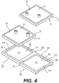
- Figs. 1 to 4 illustrate a cooling block assembly 200 in accordance with an embodiment of the present technology.
- the cooling block assembly 200 is configured for cooling a heat-generating electronic component 50 (illustrated schematically in Fig. 3 ).
- the heat-generating electronic component 50 is a central processing unit (CPU).
- the heat-generating electronic component 50 may be part of a server or other computer device operating within a data center.
- the heat-generating electronic component 50 generates a significant amount of heat and can benefit from cooling.
- the heat-generating electronic component 50 could be any other suitable heat-generating electronic component (e.g., a graphics processing unit (GPU), a memory component, a semiconductor, etc.).
- the cooling block assembly 200 includes two cooling blocks 10, a heat spreading base 160 to which the cooling blocks 10 are mounted, and a plurality of heat distributing devices 250 connected to the heat spreading base 160.
- the heat distributing devices 250 are configured for distributing heat through a phase change of a working substance contained therein.
- cooling blocks 10 are identical to each other and therefore only one of the cooling blocks 10 will be described in detail herein. It is to be understood that a similar description applies to the other cooling block 10.
- the cooling block 10 has a base 12 and a cover 14 connected to the base 12. Together, the base 12 and the cover 14 define an internal fluid conduit 15 (schematically illustrated in Fig. 5 ) within which a cooling fluid is circulated to absorb heat from the heat-generating electronic component 50. As shown in Fig. 5 , the internal fluid conduit 15 extends from an inlet 17 to an outlet 19 of the cooling block 10.
- the cooling fluid circulated through the internal fluid conduit 15 is demineralized water.
- the cooling fluid may be any other suitable cooling fluid (e.g., a refrigerant) in other embodiments.
- the cooling fluid may be capable of two-phase flow such that the cooling fluid can change phases from liquid to gas and vice-versa based on a temperature thereof. The cooling fluid circulating within the cooling block 10 will thus, at some point, be in the liquid phase, however the cooling fluid may not necessarily be in liquid phase throughout (e.g., the cooling fluid may evaporate from liquid to gas when its temperature reaches a certain value).
- the base 12 has a lower portion 16 and an upper portion 18 disposed above the lower portion 16.
- the lower portion 16 has a periphery that is smaller than a periphery of the upper portion 18 and, as such, the upper portion 18 forms a peripheral shoulder 24 that extends outwardly from an upper end of the lower portion 16.
- the lower portion 16 is positioned generally centrally relative to the upper portion 18.
- the lower portion 16 is generally square and thus has four outer surfaces.
- the lower portion 16 defines a thermal contact surface 22 of the cooling block 10, the thermal contact surface 22 being disposed on a lower side 20 of the base 12.
- the thermal contact surface 22 is the surface of the base 12 through which heat is primarily transferred to the cooling block 10. As such, in use, the thermal contact surface 22 is placed in thermal contact with another surface from which heat is to be absorbed.
- a pocket 32 is defined by the base 12 and is shaped and dimensioned to at least partly receive the cover 14 therein.
- the pocket 32 is generally square as defined by the square shape of a retaining lip section 30 defining the pocket 32.
- the retaining lip section 30 and an upper base surface 28 of the base 12 define the pocket 32 together.
- the upper base surface 28 defines a channel 34 ( Fig. 3 ) that forms in part the internal fluid conduit 15 of the cooling block 10.
- the channel 34 establishes a path of the internal fluid conduit 15 and thus guides the cooling fluid circulating therein through the cooling block 10 from the inlet 17 to the outlet 19.
- the channel 34 may have any suitable shape in different embodiments.
- the channel 34 may be shaped to define in part a serpentine path from the inlet 17 to the outlet 19.
- the cover 14 is a plate member that is generally planar and shaped to be received within the pocket 32. As shown in Fig. 5 , the cover 14 defines an inlet opening 23 and an outlet opening 25 which correspond to the inlet 17 and the outlet 19 of the cooling block 10 respectively. As such, cooling fluid is respectively fed into and discharged from the internal fluid conduit 15 through the inlet and outlet openings 23, 25 of the cover 14. Inlet and outlet ducts 40, 42 are connected to the cover 14 at the inlet and outlet openings 23, 25 respectively to fluidly connect the internal fluid conduit 15 to an external cooling fluid source.
- the external cooling fluid source may comprise a circuit of cooling equipment including one or more dry coolers installed outside of the data center. As such, during use, in this embodiment, cooling fluid is continuously recirculated between the external cooling fluid source and the cooling block 10.
- the cover 14 is received in the pocket 32 of the base 12 with a lower surface 36 of the cover 14 facing the upper base surface 28.
- the lower surface 36 is placed in contact with the upper base surface 28.
- the internal fluid conduit 15 of the liquid cooling block 10 is thus defined by the lower surface 36 of the cover 14 and the channel 34 of the base 12.
- the cover 14 could define a channel in the lower surface 36 complementary to the channel 34 of the base 12.
- the channel 34 could be omitted from the base 12 and the cover 14 could define the channel instead.
- the cover 14 has a thickness approximately equal to a height of the retaining lip section 30 such that, when the cover 14 is in place in the pocket 32, an upper (outer) surface 38 of the cover 14 is generally flush with the upper surface of the retaining lip section 30. Furthermore, in this embodiment, the cover 14 is welded to the base 12 along a periphery of the cover 14. For instance, the cover 14 may be laser welded to the base 12.
- the heat spreading base 160 has a base body 162 having an upper side 164 and a lower side 166 opposite the upper side 164.
- the base body 162 has a main portion 163 which receives the cooling blocks 10.
- the main portion 163 has two upper base surfaces 176 on the upper side 164.
- Two retaining lip sections 178 extend upward from the upper base surfaces 176 and surround respective ones of the upper base surfaces 176.
- the main portion 163 of the heat spreading base 160 defines two pockets 180, each pocket 180 being defined by one of the upper base surfaces 176 and a respective retaining lip section 178.
- the pockets 180 are shaped and dimensioned to at least partly receive the bases 12 of the cooling blocks 10.
- the two cooling blocks 10 are mated to the heat spreading base 160. More specifically, the lower portions 16 of the cooling blocks 10 are inserted into the corresponding pockets 180 of the heat spreading base 160. To that end, each pocket 180 is shaped and dimensioned such that, when the lower portion 16 of the respective cooling block 10 is inserted therein, inner surfaces 179 ( Fig. 4 ) of the retaining lip section 178 defining the pocket 180 and the outer surfaces 29 ( Fig. 6 ) of the lower portion 16 are in a close fit.
- the retaining lip sections 178 of the heat spreading base 160 thus surround the lower portions 16 of the corresponding cooling blocks 10 and thereby limit movement thereof relative to the heat spreading base 160 in horizontal directions (e.g., frontwards, backwards and laterally).
- a thermal interface material may be applied on one or both of each of the thermal contact surfaces 22 and the upper base surfaces 176.
- the base body 162 also has a boss 220 connected to the main portion 163.
- the boss 220 is disposed on the lower side 166 of the base body 162 and is spaced from a lower surface 167 of the main portion 163 in a height direction of the cooling block assembly 200.
- the lower surface 167 is on the lower side 166 of the heat spreading base 160 and is configured to face toward the heat-generating electronic component 50.
- the boss 220 is disposed underneath the main portion 163 and may be referred to as a "lower block portion" while the main portion 163 of the heat spreading base 160 together with the cooling blocks 10 can be referred to as being an "upper block portion" 189 of the cooling block assembly 200.
- the upper block portion 189 thus defines the two internal fluid conduits 15, while the boss 220 is disposed underneath the upper block portion 189 and is the part of the cooling block assembly 200 that establishes the thermal contact with the heat-generating electronic component 50.
- the boss 220 defines a thermal transfer surface 170 which is configured to be placed in thermal contact with the heat-generating electronic component 50 (with a thermal interface material disposed therebetween).
- the thermal transfer surface 170 is the surface of the heat spreading base 160 through which heat is primarily transferred to the cooling block assembly 200.
- the thermal transfer surface 170 is offset from the lower surface 167 of the upper block portion 189.
- the boss 220 and the thermal transfer surface 170 thereof are generally square.
- the dimensions of the boss 220 are significantly smaller than those of the upper block portion 189.
- the boss 220 is dimensioned to match the dimensions of the surface of the heat-generating electronic component 50.
- the boss 220 is dimensioned such that a periphery 221 of the thermal transfer surface 170 is smaller than a periphery 195 of the upper block portion 189.
- the periphery 195 of the upper block portion 189 is defined by the edges of the heat spreading base 160 that are normal to the thermal transfer surface 170.
- a ratio of an area defined by the periphery 195 of the upper block portion 189 over an area defined by the periphery 221 of the thermal transfer surface 170 is equal to or greater than 3.
- the ratio of the area defined by the periphery 195 of the upper block portion 189 over the area defined by the periphery 221 of the thermal transfer surface 170 is between 3 and 8 inclusively.
- the boss 220 is generally centered in the longitudinal and lateral directions relative to the upper block portion 189.
- the periphery 221 of the thermal transfer surface 170 is contained within the periphery 195 of the upper block portion 189 in a projection of the peripheries 221, 195 on a plane parallel to the thermal transfer surface 170.
- the heat distributing devices 250 are configured for distributing heat through a phase change of a working substance contained within each heat distributing device 250.
- two heat distributing devices 250 are provided and each heat distributing device 250 is aligned with a respective one of the internal fluid conduits 15. That is, each heat distributing device 250 is disposed underneath a respective one of the internal fluid conduits 15 to thereby spread heat to the corresponding internal fluid conduit 15. It is contemplated that, in some embodiments, a single internal fluid conduit 15 and the heat distributing devices 250 could thus be aligned with a part of the single internal fluid conduit 15.
- each heat distributing device 250 is disposed partially between the boss 220 and the lower surface 167 of the upper block portion 189 in order to distribute heat from the boss 220 to the lower surface 167.
- the heat distributing devices 250 can distribute the heat absorbed from the heat-generating electronic component 50 by the boss 220 to a larger surface, namely the lower surface 167, thereby providing efficient cooling of the heat-generating electronic component 50.
- the main portion 163 of the base body 162 defines two recesses 168 on the lower side 166 for receiving respective ones of the heat distributing devices 250.
- each recess 168 extends to an edge 169 of the base body 162. This may facilitate the installation and positioning of the heat distributing devices 250 on the heat spreading base 160.
- the heat distributing devices 250 are fastened to the heat spreading base 160.
- the heat distributing devices 250 are welded to the heat spreading base 160.
- the heat distributing devices 250 may be connected to the heat spreading base 160 in any other suitable way in other embodiments.
- the base body 162 defines two notches 185 between the lower surface 167 of the base body 162 and the boss 220.
- Each notch 185 receives a part 260 of a corresponding heat distributing device 250 therein such that the part 260 is disposed between the lower surface 167 and the boss 220.
- Each part 260 is a small proportion of the corresponding heat distributing device 250.
- each part 260 is less than half of the corresponding heat distributing device 250. As such, for each heat distributing device 250, a majority of the heat distributing device 250 is not disposed between the boss 220 and the lower surface 167.
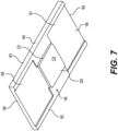
- the heat distributing devices 250 are heat pipes. More specifically, in this example, the heat distributing devices 250 are vapor chambers (i.e., planar heat pipes). As such, with reference to Fig. 8 , in this embodiment, each heat distributing device 250 functions on the basis of the working substance (e.g., water) contained therein evaporating at an evaporator side 254 of the heat distributing device 250 in response to being heated to a given temperature. The working substance thus changes phases from a liquid state to a gas state.
- the working substance e.g., water
- the gasified working substance then travels to a condenser side 256 of the heat distributing device 250, opposite the evaporator side 254, where the heat is transferred from the working substance outwards to a colder surface with which the condenser side 256 is in contact (in this case, the lower surface 167).
- the working substance thus condenses back to a liquid and travels again, through a wick material 277 to the evaporator side 254.
- each heat distributing device 250 has a casing 270 which has a heat input surface 272 (on the evaporator side 254) and a heat output surface 274 opposite the heat input surface 272.
- a portion of the heat input surface 272 (comprised by the part 260) is in contact with the boss 220.
- the heat output surface 274 is in contact with the lower surface 167 of the upper block portion 189.
- the combined surface area of the heat output surfaces 274 of the two heat distributing devices 250 is relatively large such that a majority of the lower surface 167 of the upper block portion 189 is in contact with the heat output surfaces 274. As such, the heat distributing devices 250 spread the heat absorbed thereby to a large portion of the upper block portion 189.
- a thermal interface material may be applied between the heat input surface 272 of each of the heat distributing devices 250 and the boss 200, as well as between the heat output surface 274 of each of the heat distributing devices 250 and the lower surface 167.
- the heat distributing devices 250 may be other types of heat pipes in other embodiments, including for example loop heat pipes. Furthermore, in other embodiments, the heat distributing devices 250 may be loop thermosyphons or phase changing materials.
- the cooling block assembly 200 has been shown and described as including two cooling blocks 10 and the heat spreading base 160, in other embodiments, the heat spreading base 160 may itself form the cooling blocks.
- the channels 34 corresponding to the internal fluid conduits 15 are defined by the upper base surfaces 176 of the heat spreading base 160, and the pockets 180 receive the covers 14 directly therein.
- the bases 12 are omitted.
- the upper block portion 189 comprises the heat spreading base 160 and the covers 14 which define the internal fluid conduits 15 therebetween. In cases in which the cooling block assembly 200 only has one internal fluid conduit 15, then a single cover 14 would be provided.
- the cooling block assembly 200 spreads the heat absorbed from the heat-generating electronic component 50 to a larger surface, namely the heat output surfaces 274 of the heat distributing devices 250, such that the cooling fluid circulated through the two internal fluid conduits 15 (or a larger single internal fluid conduit 15) can absorb the heat and carry it away as the cooling fluid is discharged. Therefore, the cooling block assembly 200 allows cooling a small and power dense heat-generating electronic component 50 which might otherwise be difficult for a cooling block of a size that corresponds to the size of the heat-generating electronic component 50.
Landscapes
- Engineering & Computer Science (AREA)
- Physics & Mathematics (AREA)
- Microelectronics & Electronic Packaging (AREA)
- Thermal Sciences (AREA)
- General Engineering & Computer Science (AREA)
- Mechanical Engineering (AREA)
- Theoretical Computer Science (AREA)
- Human Computer Interaction (AREA)
- General Physics & Mathematics (AREA)
- Cooling Or The Like Of Electrical Apparatus (AREA)
- Cooling Or The Like Of Semiconductors Or Solid State Devices (AREA)
- Computer Hardware Design (AREA)
Claims (12)
- Kühlblockanordnung (200) zum Kühlen eines wärmeerzeugenden elektronischen Bauteils (50), umfassend:einen oberen Blockabschnitt (189), der mindestens eine interne Flüssigkeitsleitung (15) für die Zirkulation einer Kühlflüssigkeit definiert, wobei jede der mindestens einen internen Flüssigkeitsleitung (15) einen Einlass (17) und einen Auslass (19) zum Aufnehmen bzw. Abgeben der Kühlflüssigkeit aufweist,wobei der obere Blockabschnitt (189) eine wärmeverteilende Basis (160) mit einem Basiskörper (162) umfasst, wobei eine untere Fläche (167) des Basiskörpers (162) so konfiguriert ist, dass sie dem wärmeerzeugenden elektronischen Bauteil (50) zugewandt ist;einen Vorsprung (220), der mit einem Basisabschnitt (163) des Basiskörpers (162) verbunden ist, wobei der Vorsprung (220) auf einer unteren Seite (166) des Basiskörpers (162) angeordnet ist und von der unteren Fläche (167) des Basiskörpers (162) in einer Höhenrichtung der Kühlblockanordnung (200) beabstandet ist,wobei Kerben (185) zwischen der unteren Fläche (167) des Basiskörpers (162) und dem Vorsprung (200) definiert sind, wobei der Vorsprung (220) eine Wärmeübertragungsfläche (170) aufweist,die so konfiguriert ist, dass sie in thermischem Kontakt mit dem wärmeerzeugenden elektronischen Bauteil (50) steht, wobei die Wärmeübertragungsfläche (170) von der unteren Fläche (167) des Basiskörpers (162) in der Höhenrichtung der Kühlblockanordnung (200) versetzt ist,wobei der Vorsprung (220) so bemessen ist, dass ein Umfang (221) der Wärmeübertragungsfläche (170) kleiner ist als ein Umfang (195) des Basiskörpers (162),wobei der Umfang (221) der Wärmeübertragungsfläche (170) innerhalb des Umfangs (195) des Basiskörpers (162) in einer Projektion desselben auf eine Ebene parallel zur Wärmeübertragungsfläche (170) enthalten ist; undeine Vielzahl von wärmeverteilenden Vorrichtungen (250), die zum Verteilen von Wärme durch eine Phasenveränderung einer in jeder wärmeverteilenden Vorrichtung (250) enthaltenen Arbeitssubstanz konfiguriert ist, wobei jede wärmeverteilende Vorrichtung (250) teilweise in einer entsprechenden Kerbe (185) zwischen dem Vorsprung (220) und der unteren Fläche (167) des Basiskörpers (162) angeordnet ist, um Wärme von dem Vorsprung (220) auf die untere Fläche (167) des Basiskörpers (162) zu verteilen.
- Kühlblockanordnung (200) nach Anspruch 1, wobei es sich bei den wärmeverteilenden Vorrichtungen (250) um eines der folgenden Elemente handelt: Wärmerohre, ein Phasenwechselmaterial und einen Thermosyphonkreislauf.
- Kühlblockanordnung (200) nach Anspruch 2, wobei es sich bei den wärmeverteilenden Vorrichtungen (250) um Wärmerohre handelt, wobei jedes Wärmerohr Folgendes umfasst:ein Gehäuse (270) mit einer Wärmeeingabefläche (272) in Kontakt mit dem Vorsprung und einer Wärmeausgabefläche (274) gegenüber der Wärmeeingabefläche (272), wobei die Wärmeausgabefläche (274) in Kontakt mit der unteren Fläche (167) des Basiskörpers (162) steht; unddie Arbeitssubstanz, die in dem Gehäuse (270) enthalten ist und so konfiguriert ist, dass sie nacheinander verdampft und kondensiert, um die Wärme von der Eingabefläche (272) auf die Ausgabefläche (274) zu verbreiten.
- Kühlblockanordnung (200) nach Anspruch 3, wobei es sich bei den wärmeverteilenden Vorrichtungen (250) um Dampfkammern handelt.
- Kühlblockanordnung (200) nach Anspruch 3 oder 4, wobei ein Großteil der unteren Fläche (167) des Basiskörpers (162) mit den Wärmeausgabeflächen (274) der Wärmerohre in Kontakt steht.
- Kühlblockanordnung (200) nach einem der Ansprüche 1 bis 5, wobei der Hauptabschnitt (163) des Basiskörpers (162) zwei Ausnehmungen (168) an einer Unterseite davon definiert, um die wärmeverteilenden Vorrichtungen (250) aufzunehmen.
- Kühlblockanordnung (200) nach einem der Ansprüche 1 bis 6, wobei für jede wärmeverteilende Vorrichtung (250) ein Großteil der wärmeverteilenden Vorrichtung (250) nicht zwischen dem Vorsprung (220) und der unteren Fläche (167) des Basiskörpers (162) angeordnet ist.
- Kühlblockanordnung (200) nach einem der Ansprüche 1 bis 7, wobei ein Verhältnis eines durch den Umfang (195) des Basiskörpers (162) definierten Bereichs zu einem durch den Umfang (221) der Wärmeüberführungsfläche (170) definierten Bereich gleich oder größer als 3 ist.
- Kühlblockanordnung (200) nach Anspruch 8, wobei das Verhältnis des Bereichs, der durch den Umfang (195) des Basiskörpers (162) definiert ist, zu dem Bereich, der durch den Umfang (221) der Wärmeübertragungsfläche (170) definiert ist, zwischen 3 und einschließlich 8 liegt.
- Kühlblockanordnung (200) nach einem der Ansprüche 1 bis 9, wobei:die mindestens eine Fluidleitung (15) eine erste Fluidleitung (15) und eine zweite Fluidleitung (15) beinhaltet;die Vielzahl der wärmeverteilenden Vorrichtungen (250) eine erste wärmeverteilende Vorrichtung (250) und eine zweite wärmeverteilende Vorrichtung (250) beinhaltet;die erste wärmeverteilende Vorrichtung (250) auf die erste Fluidleitung (15) ausgerichtet ist, um Wärme an die erste Fluidleitung (15) zu verteilen; unddie zweite wärmeverteilende Vorrichtung (250) auf die zweite Fluidleitung (15) ausgerichtet ist, um Wärme an die zweite Fluidleitung (15) zu verteilen; und
- Kühlblockanordnung (200) nach einem der Ansprüche 1 bis 9, wobei der obere Blockabschnitt eine Basis (12) und eine mit der Basis (12) verbundene Abdeckung (14) umfasst, wobei die mindestens eine interne Fluidleitung (15) zwischen der Basis (12) und der Abdeckung (14) definiert ist.
- Kühlblockanordnung (200) nach Anspruch 11, wobei:die mindestens eine Fluidleitung (15) eine Vielzahl von Fluidleitungen (15) ist, die eine erste Fluidleitung (15) und eine zweite Fluidleitung (15) beinhaltet;die Basis (12) eine erste Basis (12) ist und die Abdeckung (14) eine erste Abdeckung (14) ist, wobei die erste Basis (12) und die erste Abdeckung (14) die erste Fluidleitung (15) dazwischen definieren;der obere Abschnitt (189) des Blocks ferner Folgendes umfasst:eine wärmeverteilende Basis (160), die eine Vielzahl von Taschen (180) definiert, einschließlich einer ersten Tasche (180) und einer zweiten Tasche (180), wobei die erste Basis (12) in der ersten Tasche (180) aufgenommen ist;eine zweite Basis (12), die in der zweiten Tasche (180) aufgenommen ist; undeine zweite Abdeckung (14), die mit der zweiten Basis (12) verbunden ist, wobei die zweite Basis (12) und die zweite Abdeckung (14) die zweite Fluidleitung (15) dazwischen definieren.
Priority Applications (8)
| Application Number | Priority Date | Filing Date | Title |
|---|---|---|---|
| CA3182564A CA3182564A1 (en) | 2021-11-29 | 2022-11-22 | Cooling block assembly for cooling a heat-generating electronic component |
| US17/992,756 US12568603B2 (en) | 2021-11-29 | 2022-11-22 | Cooling block assembly for cooling a heat-generating electronic component |
| CA3182548A CA3182548A1 (en) | 2021-11-29 | 2022-11-22 | Method for assembling a liquid cooling assembly of a family of liquid cooling assemblies |
| US17/992,752 US12219733B2 (en) | 2021-11-29 | 2022-11-22 | Method for assembling a liquid cooling assembly of a family of liquid cooling assemblies |
| KR1020220158886A KR20230080324A (ko) | 2021-11-29 | 2022-11-24 | 발열 전자 부품의 냉각용 냉각 블록 조립체 |
| KR1020220161254A KR20230080333A (ko) | 2021-11-29 | 2022-11-28 | 액체 냉각 조립체 그룹 중 한 액체 냉각 조립체의 조립 방법 |
| CN202211503212.2A CN116185153B (zh) | 2021-11-29 | 2022-11-28 | 用于对发热电子部件进行冷却的冷却块组件 |
| CN202211502868.2A CN116193801B (zh) | 2021-11-29 | 2022-11-28 | 对成系列的液体冷却组件中的液体冷却组件组装的方法 |
Applications Claiming Priority (1)
| Application Number | Priority Date | Filing Date | Title |
|---|---|---|---|
| EP21306655.8A EP4188043B1 (de) | 2021-11-29 | 2021-11-29 | Verfahren zur montage einer flüssigkeitskühlanordnung einer familie von flüssigkeitskühlanordnungen |
Publications (2)
| Publication Number | Publication Date |
|---|---|
| EP4188047A1 EP4188047A1 (de) | 2023-05-31 |
| EP4188047B1 true EP4188047B1 (de) | 2024-05-08 |
Family
ID=78851097
Family Applications (2)
| Application Number | Title | Priority Date | Filing Date |
|---|---|---|---|
| EP21306655.8A Active EP4188043B1 (de) | 2021-11-29 | 2021-11-29 | Verfahren zur montage einer flüssigkeitskühlanordnung einer familie von flüssigkeitskühlanordnungen |
| EP22306283.7A Active EP4188047B1 (de) | 2021-11-29 | 2022-08-30 | Kühlblockanordnung zur kühlung eines wärmeerzeugenden elektronischen bauteils |
Family Applications Before (1)
| Application Number | Title | Priority Date | Filing Date |
|---|---|---|---|
| EP21306655.8A Active EP4188043B1 (de) | 2021-11-29 | 2021-11-29 | Verfahren zur montage einer flüssigkeitskühlanordnung einer familie von flüssigkeitskühlanordnungen |
Country Status (5)
| Country | Link |
|---|---|
| US (2) | US12568603B2 (de) |
| EP (2) | EP4188043B1 (de) |
| KR (2) | KR20230080324A (de) |
| CN (2) | CN116185153B (de) |
| CA (2) | CA3182548A1 (de) |
Families Citing this family (2)
| Publication number | Priority date | Publication date | Assignee | Title |
|---|---|---|---|---|
| KR102862230B1 (ko) * | 2021-01-28 | 2025-09-19 | 엘에스일렉트릭(주) | 전력기기용 히트싱크 |
| US20230328933A1 (en) * | 2022-04-11 | 2023-10-12 | Honeywell International Inc. | Integrated heat spreader |
Family Cites Families (27)
| Publication number | Priority date | Publication date | Assignee | Title |
|---|---|---|---|---|
| KR100456342B1 (ko) | 2002-02-08 | 2004-11-12 | 쿨랜스코리아 주식회사 | 반도체 칩의 수냉식 냉각 블록 |
| TWI251656B (en) | 2004-12-03 | 2006-03-21 | Hon Hai Prec Ind Co Ltd | Boiling chamber cooling device |
| US7077189B1 (en) | 2005-01-21 | 2006-07-18 | Delphi Technologies, Inc. | Liquid cooled thermosiphon with flexible coolant tubes |
| US20090065178A1 (en) | 2005-04-21 | 2009-03-12 | Nippon Light Metal Company, Ltd. | Liquid cooling jacket |
| US20080264608A1 (en) | 2007-04-30 | 2008-10-30 | Trentent Tye | Cooling mechanism comprising a heat pipe and water block |
| GB0710001D0 (en) | 2007-11-07 | 2007-11-07 | Chobanu Vadim | Universal modular waterblock |
| US20090151905A1 (en) | 2007-12-14 | 2009-06-18 | Fu Zhun Precision Industry (Shen Zhen) Co., Ltd. | Heat sink with vapor chamber |
| CN201156860Y (zh) | 2008-02-19 | 2008-11-26 | 讯凯国际股份有限公司 | 散热用水冷头结构 |
| US7978472B2 (en) | 2009-06-10 | 2011-07-12 | International Business Machines Corporation | Liquid-cooled cooling apparatus, electronics rack and methods of fabrication thereof |
| US20130168068A1 (en) | 2011-12-29 | 2013-07-04 | International Business Machines Corporation | Thermally enhanced cold plate having high conductivity thermal transfer paths |
| CN104238698B (zh) | 2014-08-01 | 2017-07-25 | 北京市鑫全盛商贸有限公司 | 用于水冷式cpu散热器的水冷头 |
| US10006571B2 (en) * | 2014-08-27 | 2018-06-26 | International Business Machines Corporation | Releasable, threadless conduit connector for liquid manifold |
| TWM500919U (zh) | 2015-01-29 | 2015-05-11 | 訊凱國際股份有限公司 | 水冷散熱裝置及其水冷頭 |
| TWM512883U (zh) * | 2015-05-05 | 2015-11-21 | 訊凱國際股份有限公司 | 散熱模組、水冷式散熱模組及散熱系統 |
| TWM522550U (zh) | 2015-10-26 | 2016-05-21 | 邁萪科技股份有限公司 | 散熱結構及包含該結構的水冷頭 |
| US10191521B2 (en) | 2017-05-25 | 2019-01-29 | Coolanyp, LLC | Hub-link liquid cooling system |
| US20190234691A1 (en) | 2018-01-26 | 2019-08-01 | Taiwan Microloops Corp. | Thermal module |
| CN209676753U (zh) | 2018-01-30 | 2019-11-22 | 讯凯国际股份有限公司 | 液冷式热交换装置 |
| PL3792576T3 (pl) * | 2018-09-04 | 2023-02-20 | Ovh | Blok wodny zawierający przewód płynowy |
| US10809776B2 (en) | 2018-10-03 | 2020-10-20 | Asia Vital Components (China) Co., Ltd. | Water block mounting holder with reinforced structure |
| EP3742097B1 (de) * | 2019-05-23 | 2023-09-06 | Ovh | Wasserblockanordnung |
| US12284793B2 (en) * | 2019-12-27 | 2025-04-22 | Intel Corporation | Cooling systems, cooling structures and electronic devices and methods for manufacturing or operating cooling systems, cooling structures and electronic devices |
| EP3917300B1 (de) * | 2020-05-29 | 2022-12-28 | Ovh | Unterbrechungsfreie stromversorgung mit einer flüssigkeitskühlvorrichtung |
| US12402287B2 (en) * | 2020-05-29 | 2025-08-26 | Ovh | Uninterruptible power supply having a liquid cooling device |
| CN114121849B (zh) * | 2020-08-27 | 2025-10-31 | 讯凯国际股份有限公司 | 水冷散热装置及其制造方法 |
| CN112201637A (zh) * | 2020-11-03 | 2021-01-08 | 深圳市森若新材科技有限公司 | 相变液冷散热装置 |
| US11800682B2 (en) * | 2021-12-03 | 2023-10-24 | Hewlett Packard Enterprise Development Lp | Cooling module and a method of assembling the cooling module to an electronic circuit module |
-
2021
- 2021-11-29 EP EP21306655.8A patent/EP4188043B1/de active Active
-
2022
- 2022-08-30 EP EP22306283.7A patent/EP4188047B1/de active Active
- 2022-11-22 CA CA3182548A patent/CA3182548A1/en active Pending
- 2022-11-22 CA CA3182564A patent/CA3182564A1/en active Pending
- 2022-11-22 US US17/992,756 patent/US12568603B2/en active Active
- 2022-11-22 US US17/992,752 patent/US12219733B2/en active Active
- 2022-11-24 KR KR1020220158886A patent/KR20230080324A/ko active Pending
- 2022-11-28 CN CN202211503212.2A patent/CN116185153B/zh active Active
- 2022-11-28 KR KR1020220161254A patent/KR20230080333A/ko active Pending
- 2022-11-28 CN CN202211502868.2A patent/CN116193801B/zh active Active
Also Published As
| Publication number | Publication date |
|---|---|
| KR20230080324A (ko) | 2023-06-07 |
| US20230171925A1 (en) | 2023-06-01 |
| CN116185153B (zh) | 2025-07-15 |
| CN116185153A (zh) | 2023-05-30 |
| US12568603B2 (en) | 2026-03-03 |
| US20230171926A1 (en) | 2023-06-01 |
| EP4188043B1 (de) | 2025-04-02 |
| KR20230080333A (ko) | 2023-06-07 |
| EP4188043A1 (de) | 2023-05-31 |
| CA3182548A1 (en) | 2023-05-29 |
| EP4188047A1 (de) | 2023-05-31 |
| CN116193801A (zh) | 2023-05-30 |
| CA3182564A1 (en) | 2023-05-29 |
| CN116193801B (zh) | 2025-05-23 |
| US12219733B2 (en) | 2025-02-04 |
Similar Documents
| Publication | Publication Date | Title |
|---|---|---|
| CN108279759B (zh) | 一种液体冷却系统 | |
| CN102834688B (zh) | 相变冷却器和设有该相变冷却器的电子设备 | |
| US20200201403A1 (en) | Cooling apparatus | |
| EP4188047B1 (de) | Kühlblockanordnung zur kühlung eines wärmeerzeugenden elektronischen bauteils | |
| JP7288998B2 (ja) | 目詰まり防止機構を有するコールドプレート | |
| US9848515B1 (en) | Multi-compartment computing device with shared cooling device | |
| JP2024513805A (ja) | 液冷放熱機器、キャビネット及びシステム | |
| JPWO2015146110A1 (ja) | 相変化冷却器および相変化冷却方法 | |
| KR100817267B1 (ko) | 냉각재킷 | |
| EP1513386A2 (de) | Elektronisches Gerät | |
| CN1980564A (zh) | 用于冷却电子部件的混合散热器和方法 | |
| CN117425309A (zh) | 散热器及电子设备 | |
| CN115190736A (zh) | 一种计算设备及机柜 | |
| TW202334598A (zh) | 液冷散熱裝置及具有該液冷散熱裝置的液冷散熱系統 | |
| JP5252059B2 (ja) | 冷却装置 | |
| CN115209692B (zh) | 散热的电子设备和服务器 | |
| US12029013B2 (en) | Cooling plate with coaxial fluid port | |
| US7661465B2 (en) | Integrated cooling system with multiple condensing passages for cooling electronic components | |
| CN117241540A (zh) | 冷却系统及伺服器 | |
| US20070139888A1 (en) | Heat transfer system | |
| US7757750B2 (en) | Integrated cooling system for electronic components | |
| CN220402207U (zh) | 一种换热装置及散热设备 | |
| CN221551180U (zh) | 冷板及计算设备 | |
| CN117651401A (zh) | 散热模组和电子设备 | |
| CN118524684A (zh) | 一种散热结构、电子设备 |
Legal Events
| Date | Code | Title | Description |
|---|---|---|---|
| PUAI | Public reference made under article 153(3) epc to a published international application that has entered the european phase |
Free format text: ORIGINAL CODE: 0009012 |
|
| STAA | Information on the status of an ep patent application or granted ep patent |
Free format text: STATUS: THE APPLICATION HAS BEEN PUBLISHED |
|
| AK | Designated contracting states |
Kind code of ref document: A1 Designated state(s): AL AT BE BG CH CY CZ DE DK EE ES FI FR GB GR HR HU IE IS IT LI LT LU LV MC MK MT NL NO PL PT RO RS SE SI SK SM TR |
|
| STAA | Information on the status of an ep patent application or granted ep patent |
Free format text: STATUS: REQUEST FOR EXAMINATION WAS MADE |
|
| 17P | Request for examination filed |
Effective date: 20231011 |
|
| RBV | Designated contracting states (corrected) |
Designated state(s): AL AT BE BG CH CY CZ DE DK EE ES FI FR GB GR HR HU IE IS IT LI LT LU LV MC MK MT NL NO PL PT RO RS SE SI SK SM TR |
|
| GRAP | Despatch of communication of intention to grant a patent |
Free format text: ORIGINAL CODE: EPIDOSNIGR1 |
|
| STAA | Information on the status of an ep patent application or granted ep patent |
Free format text: STATUS: GRANT OF PATENT IS INTENDED |
|
| RIC1 | Information provided on ipc code assigned before grant |
Ipc: H01L 21/48 20060101ALI20231231BHEP Ipc: F28D 21/00 20060101ALI20231231BHEP Ipc: F28F 3/12 20060101ALI20231231BHEP Ipc: H01L 23/473 20060101ALI20231231BHEP Ipc: F28D 1/03 20060101ALI20231231BHEP Ipc: H05K 7/20 20060101AFI20231231BHEP |
|
| INTG | Intention to grant announced |
Effective date: 20240201 |
|
| GRAS | Grant fee paid |
Free format text: ORIGINAL CODE: EPIDOSNIGR3 |
|
| GRAA | (expected) grant |
Free format text: ORIGINAL CODE: 0009210 |
|
| STAA | Information on the status of an ep patent application or granted ep patent |
Free format text: STATUS: THE PATENT HAS BEEN GRANTED |
|
| AK | Designated contracting states |
Kind code of ref document: B1 Designated state(s): AL AT BE BG CH CY CZ DE DK EE ES FI FR GB GR HR HU IE IS IT LI LT LU LV MC MK MT NL NO PL PT RO RS SE SI SK SM TR |
|
| REG | Reference to a national code |
Ref country code: GB Ref legal event code: FG4D |
|
| REG | Reference to a national code |
Ref country code: CH Ref legal event code: EP |
|
| REG | Reference to a national code |
Ref country code: DE Ref legal event code: R096 Ref document number: 602022003372 Country of ref document: DE |
|
| P01 | Opt-out of the competence of the unified patent court (upc) registered |
Effective date: 20240423 |
|
| REG | Reference to a national code |
Ref country code: IE Ref legal event code: FG4D |
|
| REG | Reference to a national code |
Ref country code: LT Ref legal event code: MG9D |
|
| PG25 | Lapsed in a contracting state [announced via postgrant information from national office to epo] |
Ref country code: IS Free format text: LAPSE BECAUSE OF FAILURE TO SUBMIT A TRANSLATION OF THE DESCRIPTION OR TO PAY THE FEE WITHIN THE PRESCRIBED TIME-LIMIT Effective date: 20240908 |
|
| PG25 | Lapsed in a contracting state [announced via postgrant information from national office to epo] |
Ref country code: BG Free format text: LAPSE BECAUSE OF FAILURE TO SUBMIT A TRANSLATION OF THE DESCRIPTION OR TO PAY THE FEE WITHIN THE PRESCRIBED TIME-LIMIT Effective date: 20240508 |
|
| PG25 | Lapsed in a contracting state [announced via postgrant information from national office to epo] |
Ref country code: HR Free format text: LAPSE BECAUSE OF FAILURE TO SUBMIT A TRANSLATION OF THE DESCRIPTION OR TO PAY THE FEE WITHIN THE PRESCRIBED TIME-LIMIT Effective date: 20240508 Ref country code: FI Free format text: LAPSE BECAUSE OF FAILURE TO SUBMIT A TRANSLATION OF THE DESCRIPTION OR TO PAY THE FEE WITHIN THE PRESCRIBED TIME-LIMIT Effective date: 20240508 |
|
| PG25 | Lapsed in a contracting state [announced via postgrant information from national office to epo] |
Ref country code: GR Free format text: LAPSE BECAUSE OF FAILURE TO SUBMIT A TRANSLATION OF THE DESCRIPTION OR TO PAY THE FEE WITHIN THE PRESCRIBED TIME-LIMIT Effective date: 20240809 |
|
| PG25 | Lapsed in a contracting state [announced via postgrant information from national office to epo] |
Ref country code: PT Free format text: LAPSE BECAUSE OF FAILURE TO SUBMIT A TRANSLATION OF THE DESCRIPTION OR TO PAY THE FEE WITHIN THE PRESCRIBED TIME-LIMIT Effective date: 20240909 |
|
| REG | Reference to a national code |
Ref country code: AT Ref legal event code: MK05 Ref document number: 1686062 Country of ref document: AT Kind code of ref document: T Effective date: 20240508 |
|
| PG25 | Lapsed in a contracting state [announced via postgrant information from national office to epo] |
Ref country code: NL Free format text: LAPSE BECAUSE OF FAILURE TO SUBMIT A TRANSLATION OF THE DESCRIPTION OR TO PAY THE FEE WITHIN THE PRESCRIBED TIME-LIMIT Effective date: 20240508 |
|
| PG25 | Lapsed in a contracting state [announced via postgrant information from national office to epo] |
Ref country code: ES Free format text: LAPSE BECAUSE OF FAILURE TO SUBMIT A TRANSLATION OF THE DESCRIPTION OR TO PAY THE FEE WITHIN THE PRESCRIBED TIME-LIMIT Effective date: 20240508 |
|
| PG25 | Lapsed in a contracting state [announced via postgrant information from national office to epo] |
Ref country code: AT Free format text: LAPSE BECAUSE OF FAILURE TO SUBMIT A TRANSLATION OF THE DESCRIPTION OR TO PAY THE FEE WITHIN THE PRESCRIBED TIME-LIMIT Effective date: 20240508 |
|
| PG25 | Lapsed in a contracting state [announced via postgrant information from national office to epo] |
Ref country code: PL Free format text: LAPSE BECAUSE OF FAILURE TO SUBMIT A TRANSLATION OF THE DESCRIPTION OR TO PAY THE FEE WITHIN THE PRESCRIBED TIME-LIMIT Effective date: 20240508 |
|
| PG25 | Lapsed in a contracting state [announced via postgrant information from national office to epo] |
Ref country code: LV Free format text: LAPSE BECAUSE OF FAILURE TO SUBMIT A TRANSLATION OF THE DESCRIPTION OR TO PAY THE FEE WITHIN THE PRESCRIBED TIME-LIMIT Effective date: 20240508 |
|
| PG25 | Lapsed in a contracting state [announced via postgrant information from national office to epo] |
Ref country code: PT Free format text: LAPSE BECAUSE OF FAILURE TO SUBMIT A TRANSLATION OF THE DESCRIPTION OR TO PAY THE FEE WITHIN THE PRESCRIBED TIME-LIMIT Effective date: 20240909 Ref country code: PL Free format text: LAPSE BECAUSE OF FAILURE TO SUBMIT A TRANSLATION OF THE DESCRIPTION OR TO PAY THE FEE WITHIN THE PRESCRIBED TIME-LIMIT Effective date: 20240508 Ref country code: NO Free format text: LAPSE BECAUSE OF FAILURE TO SUBMIT A TRANSLATION OF THE DESCRIPTION OR TO PAY THE FEE WITHIN THE PRESCRIBED TIME-LIMIT Effective date: 20240808 Ref country code: NL Free format text: LAPSE BECAUSE OF FAILURE TO SUBMIT A TRANSLATION OF THE DESCRIPTION OR TO PAY THE FEE WITHIN THE PRESCRIBED TIME-LIMIT Effective date: 20240508 Ref country code: LV Free format text: LAPSE BECAUSE OF FAILURE TO SUBMIT A TRANSLATION OF THE DESCRIPTION OR TO PAY THE FEE WITHIN THE PRESCRIBED TIME-LIMIT Effective date: 20240508 Ref country code: IS Free format text: LAPSE BECAUSE OF FAILURE TO SUBMIT A TRANSLATION OF THE DESCRIPTION OR TO PAY THE FEE WITHIN THE PRESCRIBED TIME-LIMIT Effective date: 20240908 Ref country code: HR Free format text: LAPSE BECAUSE OF FAILURE TO SUBMIT A TRANSLATION OF THE DESCRIPTION OR TO PAY THE FEE WITHIN THE PRESCRIBED TIME-LIMIT Effective date: 20240508 Ref country code: GR Free format text: LAPSE BECAUSE OF FAILURE TO SUBMIT A TRANSLATION OF THE DESCRIPTION OR TO PAY THE FEE WITHIN THE PRESCRIBED TIME-LIMIT Effective date: 20240809 Ref country code: FI Free format text: LAPSE BECAUSE OF FAILURE TO SUBMIT A TRANSLATION OF THE DESCRIPTION OR TO PAY THE FEE WITHIN THE PRESCRIBED TIME-LIMIT Effective date: 20240508 Ref country code: ES Free format text: LAPSE BECAUSE OF FAILURE TO SUBMIT A TRANSLATION OF THE DESCRIPTION OR TO PAY THE FEE WITHIN THE PRESCRIBED TIME-LIMIT Effective date: 20240508 Ref country code: BG Free format text: LAPSE BECAUSE OF FAILURE TO SUBMIT A TRANSLATION OF THE DESCRIPTION OR TO PAY THE FEE WITHIN THE PRESCRIBED TIME-LIMIT Effective date: 20240508 Ref country code: AT Free format text: LAPSE BECAUSE OF FAILURE TO SUBMIT A TRANSLATION OF THE DESCRIPTION OR TO PAY THE FEE WITHIN THE PRESCRIBED TIME-LIMIT Effective date: 20240508 Ref country code: RS Free format text: LAPSE BECAUSE OF FAILURE TO SUBMIT A TRANSLATION OF THE DESCRIPTION OR TO PAY THE FEE WITHIN THE PRESCRIBED TIME-LIMIT Effective date: 20240808 |
|
| PG25 | Lapsed in a contracting state [announced via postgrant information from national office to epo] |
Ref country code: DK Free format text: LAPSE BECAUSE OF FAILURE TO SUBMIT A TRANSLATION OF THE DESCRIPTION OR TO PAY THE FEE WITHIN THE PRESCRIBED TIME-LIMIT Effective date: 20240508 |
|
| PG25 | Lapsed in a contracting state [announced via postgrant information from national office to epo] |
Ref country code: EE Free format text: LAPSE BECAUSE OF FAILURE TO SUBMIT A TRANSLATION OF THE DESCRIPTION OR TO PAY THE FEE WITHIN THE PRESCRIBED TIME-LIMIT Effective date: 20240508 |
|
| PG25 | Lapsed in a contracting state [announced via postgrant information from national office to epo] |
Ref country code: CZ Free format text: LAPSE BECAUSE OF FAILURE TO SUBMIT A TRANSLATION OF THE DESCRIPTION OR TO PAY THE FEE WITHIN THE PRESCRIBED TIME-LIMIT Effective date: 20240508 |
|
| PG25 | Lapsed in a contracting state [announced via postgrant information from national office to epo] |
Ref country code: SK Free format text: LAPSE BECAUSE OF FAILURE TO SUBMIT A TRANSLATION OF THE DESCRIPTION OR TO PAY THE FEE WITHIN THE PRESCRIBED TIME-LIMIT Effective date: 20240508 Ref country code: RO Free format text: LAPSE BECAUSE OF FAILURE TO SUBMIT A TRANSLATION OF THE DESCRIPTION OR TO PAY THE FEE WITHIN THE PRESCRIBED TIME-LIMIT Effective date: 20240508 |
|
| PG25 | Lapsed in a contracting state [announced via postgrant information from national office to epo] |
Ref country code: SM Free format text: LAPSE BECAUSE OF FAILURE TO SUBMIT A TRANSLATION OF THE DESCRIPTION OR TO PAY THE FEE WITHIN THE PRESCRIBED TIME-LIMIT Effective date: 20240508 |
|
| PG25 | Lapsed in a contracting state [announced via postgrant information from national office to epo] |
Ref country code: SM Free format text: LAPSE BECAUSE OF FAILURE TO SUBMIT A TRANSLATION OF THE DESCRIPTION OR TO PAY THE FEE WITHIN THE PRESCRIBED TIME-LIMIT Effective date: 20240508 Ref country code: SK Free format text: LAPSE BECAUSE OF FAILURE TO SUBMIT A TRANSLATION OF THE DESCRIPTION OR TO PAY THE FEE WITHIN THE PRESCRIBED TIME-LIMIT Effective date: 20240508 Ref country code: RO Free format text: LAPSE BECAUSE OF FAILURE TO SUBMIT A TRANSLATION OF THE DESCRIPTION OR TO PAY THE FEE WITHIN THE PRESCRIBED TIME-LIMIT Effective date: 20240508 Ref country code: EE Free format text: LAPSE BECAUSE OF FAILURE TO SUBMIT A TRANSLATION OF THE DESCRIPTION OR TO PAY THE FEE WITHIN THE PRESCRIBED TIME-LIMIT Effective date: 20240508 Ref country code: DK Free format text: LAPSE BECAUSE OF FAILURE TO SUBMIT A TRANSLATION OF THE DESCRIPTION OR TO PAY THE FEE WITHIN THE PRESCRIBED TIME-LIMIT Effective date: 20240508 Ref country code: CZ Free format text: LAPSE BECAUSE OF FAILURE TO SUBMIT A TRANSLATION OF THE DESCRIPTION OR TO PAY THE FEE WITHIN THE PRESCRIBED TIME-LIMIT Effective date: 20240508 |
|
| PG25 | Lapsed in a contracting state [announced via postgrant information from national office to epo] |
Ref country code: IT Free format text: LAPSE BECAUSE OF FAILURE TO SUBMIT A TRANSLATION OF THE DESCRIPTION OR TO PAY THE FEE WITHIN THE PRESCRIBED TIME-LIMIT Effective date: 20240508 |
|
| REG | Reference to a national code |
Ref country code: DE Ref legal event code: R097 Ref document number: 602022003372 Country of ref document: DE |
|
| PLBE | No opposition filed within time limit |
Free format text: ORIGINAL CODE: 0009261 |
|
| STAA | Information on the status of an ep patent application or granted ep patent |
Free format text: STATUS: NO OPPOSITION FILED WITHIN TIME LIMIT |
|
| 26N | No opposition filed |
Effective date: 20250211 |
|
| PG25 | Lapsed in a contracting state [announced via postgrant information from national office to epo] |
Ref country code: LU Free format text: LAPSE BECAUSE OF NON-PAYMENT OF DUE FEES Effective date: 20240830 |
|
| PG25 | Lapsed in a contracting state [announced via postgrant information from national office to epo] |
Ref country code: SI Free format text: LAPSE BECAUSE OF FAILURE TO SUBMIT A TRANSLATION OF THE DESCRIPTION OR TO PAY THE FEE WITHIN THE PRESCRIBED TIME-LIMIT Effective date: 20240508 Ref country code: MC Free format text: LAPSE BECAUSE OF FAILURE TO SUBMIT A TRANSLATION OF THE DESCRIPTION OR TO PAY THE FEE WITHIN THE PRESCRIBED TIME-LIMIT Effective date: 20240508 |
|
| REG | Reference to a national code |
Ref country code: BE Ref legal event code: MM Effective date: 20240831 |
|
| PG25 | Lapsed in a contracting state [announced via postgrant information from national office to epo] |
Ref country code: BE Free format text: LAPSE BECAUSE OF NON-PAYMENT OF DUE FEES Effective date: 20240831 |
|
| PG25 | Lapsed in a contracting state [announced via postgrant information from national office to epo] |
Ref country code: IE Free format text: LAPSE BECAUSE OF NON-PAYMENT OF DUE FEES Effective date: 20240830 |
|
| PG25 | Lapsed in a contracting state [announced via postgrant information from national office to epo] |
Ref country code: SE Free format text: LAPSE BECAUSE OF FAILURE TO SUBMIT A TRANSLATION OF THE DESCRIPTION OR TO PAY THE FEE WITHIN THE PRESCRIBED TIME-LIMIT Effective date: 20240508 |
|
| PGFP | Annual fee paid to national office [announced via postgrant information from national office to epo] |
Ref country code: DE Payment date: 20250820 Year of fee payment: 4 |
|
| PGFP | Annual fee paid to national office [announced via postgrant information from national office to epo] |
Ref country code: FR Payment date: 20250820 Year of fee payment: 4 |
|
| PG25 | Lapsed in a contracting state [announced via postgrant information from national office to epo] |
Ref country code: CY Free format text: LAPSE BECAUSE OF FAILURE TO SUBMIT A TRANSLATION OF THE DESCRIPTION OR TO PAY THE FEE WITHIN THE PRESCRIBED TIME-LIMIT; INVALID AB INITIO Effective date: 20220830 |
|
| PG25 | Lapsed in a contracting state [announced via postgrant information from national office to epo] |
Ref country code: HU Free format text: LAPSE BECAUSE OF FAILURE TO SUBMIT A TRANSLATION OF THE DESCRIPTION OR TO PAY THE FEE WITHIN THE PRESCRIBED TIME-LIMIT; INVALID AB INITIO Effective date: 20220830 |
|
| REG | Reference to a national code |
Ref country code: CH Ref legal event code: H13 Free format text: ST27 STATUS EVENT CODE: U-0-0-H10-H13 (AS PROVIDED BY THE NATIONAL OFFICE) Effective date: 20260324 |