EP4187684B1 - Batteriesatz - Google Patents
Batteriesatz Download PDFInfo
- Publication number
- EP4187684B1 EP4187684B1 EP21921633.0A EP21921633A EP4187684B1 EP 4187684 B1 EP4187684 B1 EP 4187684B1 EP 21921633 A EP21921633 A EP 21921633A EP 4187684 B1 EP4187684 B1 EP 4187684B1
- Authority
- EP
- European Patent Office
- Prior art keywords
- battery
- battery cell
- battery pack
- region
- positive electrode
- Prior art date
- Legal status (The legal status is an assumption and is not a legal conclusion. Google has not performed a legal analysis and makes no representation as to the accuracy of the status listed.)
- Active
Links
Images


Classifications
-
- H—ELECTRICITY
- H01—ELECTRIC ELEMENTS
- H01M—PROCESSES OR MEANS, e.g. BATTERIES, FOR THE DIRECT CONVERSION OF CHEMICAL ENERGY INTO ELECTRICAL ENERGY
- H01M10/00—Secondary cells; Manufacture thereof
- H01M10/05—Accumulators with non-aqueous electrolyte
- H01M10/052—Li-accumulators
- H01M10/0525—Rocking-chair batteries, i.e. batteries with lithium insertion or intercalation in both electrodes; Lithium-ion batteries
-
- H—ELECTRICITY
- H01—ELECTRIC ELEMENTS
- H01M—PROCESSES OR MEANS, e.g. BATTERIES, FOR THE DIRECT CONVERSION OF CHEMICAL ENERGY INTO ELECTRICAL ENERGY
- H01M10/00—Secondary cells; Manufacture thereof
- H01M10/42—Methods or arrangements for servicing or maintenance of secondary cells or secondary half-cells
- H01M10/425—Structural combination with electronic components, e.g. electronic circuits integrated to the outside of the casing
-
- H—ELECTRICITY
- H01—ELECTRIC ELEMENTS
- H01M—PROCESSES OR MEANS, e.g. BATTERIES, FOR THE DIRECT CONVERSION OF CHEMICAL ENERGY INTO ELECTRICAL ENERGY
- H01M10/00—Secondary cells; Manufacture thereof
- H01M10/42—Methods or arrangements for servicing or maintenance of secondary cells or secondary half-cells
- H01M10/44—Methods for charging or discharging
- H01M10/441—Methods for charging or discharging for several batteries or cells simultaneously or sequentially
-
- H—ELECTRICITY
- H01—ELECTRIC ELEMENTS
- H01M—PROCESSES OR MEANS, e.g. BATTERIES, FOR THE DIRECT CONVERSION OF CHEMICAL ENERGY INTO ELECTRICAL ENERGY
- H01M10/00—Secondary cells; Manufacture thereof
- H01M10/42—Methods or arrangements for servicing or maintenance of secondary cells or secondary half-cells
- H01M10/44—Methods for charging or discharging
- H01M10/443—Methods for charging or discharging in response to temperature
-
- H—ELECTRICITY
- H01—ELECTRIC ELEMENTS
- H01M—PROCESSES OR MEANS, e.g. BATTERIES, FOR THE DIRECT CONVERSION OF CHEMICAL ENERGY INTO ELECTRICAL ENERGY
- H01M10/00—Secondary cells; Manufacture thereof
- H01M10/42—Methods or arrangements for servicing or maintenance of secondary cells or secondary half-cells
- H01M10/48—Accumulators combined with arrangements for measuring, testing or indicating the condition of cells, e.g. the level or density of the electrolyte
- H01M10/486—Accumulators combined with arrangements for measuring, testing or indicating the condition of cells, e.g. the level or density of the electrolyte for measuring temperature
-
- H—ELECTRICITY
- H01—ELECTRIC ELEMENTS
- H01M—PROCESSES OR MEANS, e.g. BATTERIES, FOR THE DIRECT CONVERSION OF CHEMICAL ENERGY INTO ELECTRICAL ENERGY
- H01M10/00—Secondary cells; Manufacture thereof
- H01M10/60—Heating or cooling; Temperature control
- H01M10/61—Types of temperature control
- H01M10/613—Cooling or keeping cold
-
- H—ELECTRICITY
- H01—ELECTRIC ELEMENTS
- H01M—PROCESSES OR MEANS, e.g. BATTERIES, FOR THE DIRECT CONVERSION OF CHEMICAL ENERGY INTO ELECTRICAL ENERGY
- H01M10/00—Secondary cells; Manufacture thereof
- H01M10/60—Heating or cooling; Temperature control
- H01M10/61—Types of temperature control
- H01M10/617—Types of temperature control for achieving uniformity or desired distribution of temperature
-
- H—ELECTRICITY
- H01—ELECTRIC ELEMENTS
- H01M—PROCESSES OR MEANS, e.g. BATTERIES, FOR THE DIRECT CONVERSION OF CHEMICAL ENERGY INTO ELECTRICAL ENERGY
- H01M10/00—Secondary cells; Manufacture thereof
- H01M10/60—Heating or cooling; Temperature control
- H01M10/64—Heating or cooling; Temperature control characterised by the shape of the cells
- H01M10/643—Cylindrical cells
-
- H—ELECTRICITY
- H01—ELECTRIC ELEMENTS
- H01M—PROCESSES OR MEANS, e.g. BATTERIES, FOR THE DIRECT CONVERSION OF CHEMICAL ENERGY INTO ELECTRICAL ENERGY
- H01M4/00—Electrodes
- H01M4/02—Electrodes composed of, or comprising, active material
- H01M4/36—Selection of substances as active materials, active masses, active liquids
- H01M4/48—Selection of substances as active materials, active masses, active liquids of inorganic oxides or hydroxides
- H01M4/50—Selection of substances as active materials, active masses, active liquids of inorganic oxides or hydroxides of manganese
- H01M4/505—Selection of substances as active materials, active masses, active liquids of inorganic oxides or hydroxides of manganese of mixed oxides or hydroxides containing manganese for inserting or intercalating light metals, e.g. LiMn2O4 or LiMn2OxFy
-
- H—ELECTRICITY
- H01—ELECTRIC ELEMENTS
- H01M—PROCESSES OR MEANS, e.g. BATTERIES, FOR THE DIRECT CONVERSION OF CHEMICAL ENERGY INTO ELECTRICAL ENERGY
- H01M4/00—Electrodes
- H01M4/02—Electrodes composed of, or comprising, active material
- H01M4/36—Selection of substances as active materials, active masses, active liquids
- H01M4/48—Selection of substances as active materials, active masses, active liquids of inorganic oxides or hydroxides
- H01M4/52—Selection of substances as active materials, active masses, active liquids of inorganic oxides or hydroxides of nickel, cobalt or iron
- H01M4/525—Selection of substances as active materials, active masses, active liquids of inorganic oxides or hydroxides of nickel, cobalt or iron of mixed oxides or hydroxides containing iron, cobalt or nickel for inserting or intercalating light metals, e.g. LiNiO2, LiCoO2 or LiCoOxFy
-
- H—ELECTRICITY
- H01—ELECTRIC ELEMENTS
- H01M—PROCESSES OR MEANS, e.g. BATTERIES, FOR THE DIRECT CONVERSION OF CHEMICAL ENERGY INTO ELECTRICAL ENERGY
- H01M4/00—Electrodes
- H01M4/02—Electrodes composed of, or comprising, active material
- H01M4/36—Selection of substances as active materials, active masses, active liquids
- H01M4/58—Selection of substances as active materials, active masses, active liquids of inorganic compounds other than oxides or hydroxides, e.g. sulfides, selenides, tellurides, halogenides or LiCoFy; of polyanionic structures, e.g. phosphates, silicates or borates
- H01M4/5825—Oxygenated metallic salts or polyanionic structures, e.g. borates, phosphates, silicates, olivines
-
- H—ELECTRICITY
- H01—ELECTRIC ELEMENTS
- H01M—PROCESSES OR MEANS, e.g. BATTERIES, FOR THE DIRECT CONVERSION OF CHEMICAL ENERGY INTO ELECTRICAL ENERGY
- H01M50/00—Constructional details or processes of manufacture of the non-active parts of electrochemical cells other than fuel cells, e.g. hybrid cells
- H01M50/20—Mountings; Secondary casings or frames; Racks, modules or packs; Suspension devices; Shock absorbers; Transport or carrying devices; Holders
- H01M50/204—Racks, modules or packs for multiple batteries or multiple cells
- H01M50/207—Racks, modules or packs for multiple batteries or multiple cells characterised by their shape
- H01M50/209—Racks, modules or packs for multiple batteries or multiple cells characterised by their shape adapted for prismatic or rectangular cells
-
- H—ELECTRICITY
- H01—ELECTRIC ELEMENTS
- H01M—PROCESSES OR MEANS, e.g. BATTERIES, FOR THE DIRECT CONVERSION OF CHEMICAL ENERGY INTO ELECTRICAL ENERGY
- H01M50/00—Constructional details or processes of manufacture of the non-active parts of electrochemical cells other than fuel cells, e.g. hybrid cells
- H01M50/20—Mountings; Secondary casings or frames; Racks, modules or packs; Suspension devices; Shock absorbers; Transport or carrying devices; Holders
- H01M50/204—Racks, modules or packs for multiple batteries or multiple cells
- H01M50/207—Racks, modules or packs for multiple batteries or multiple cells characterised by their shape
- H01M50/211—Racks, modules or packs for multiple batteries or multiple cells characterised by their shape adapted for pouch cells
-
- H—ELECTRICITY
- H01—ELECTRIC ELEMENTS
- H01M—PROCESSES OR MEANS, e.g. BATTERIES, FOR THE DIRECT CONVERSION OF CHEMICAL ENERGY INTO ELECTRICAL ENERGY
- H01M50/00—Constructional details or processes of manufacture of the non-active parts of electrochemical cells other than fuel cells, e.g. hybrid cells
- H01M50/20—Mountings; Secondary casings or frames; Racks, modules or packs; Suspension devices; Shock absorbers; Transport or carrying devices; Holders
- H01M50/204—Racks, modules or packs for multiple batteries or multiple cells
- H01M50/207—Racks, modules or packs for multiple batteries or multiple cells characterised by their shape
- H01M50/213—Racks, modules or packs for multiple batteries or multiple cells characterised by their shape adapted for cells having curved cross-section, e.g. round or elliptic
-
- H—ELECTRICITY
- H01—ELECTRIC ELEMENTS
- H01M—PROCESSES OR MEANS, e.g. BATTERIES, FOR THE DIRECT CONVERSION OF CHEMICAL ENERGY INTO ELECTRICAL ENERGY
- H01M50/00—Constructional details or processes of manufacture of the non-active parts of electrochemical cells other than fuel cells, e.g. hybrid cells
- H01M50/20—Mountings; Secondary casings or frames; Racks, modules or packs; Suspension devices; Shock absorbers; Transport or carrying devices; Holders
- H01M50/267—Mountings; Secondary casings or frames; Racks, modules or packs; Suspension devices; Shock absorbers; Transport or carrying devices; Holders having means for adapting to batteries or cells of different types or different sizes
-
- H—ELECTRICITY
- H01—ELECTRIC ELEMENTS
- H01M—PROCESSES OR MEANS, e.g. BATTERIES, FOR THE DIRECT CONVERSION OF CHEMICAL ENERGY INTO ELECTRICAL ENERGY
- H01M10/00—Secondary cells; Manufacture thereof
- H01M10/42—Methods or arrangements for servicing or maintenance of secondary cells or secondary half-cells
- H01M10/425—Structural combination with electronic components, e.g. electronic circuits integrated to the outside of the casing
- H01M2010/4271—Battery management systems including electronic circuits, e.g. control of current or voltage to keep battery in healthy state, cell balancing
-
- H—ELECTRICITY
- H01—ELECTRIC ELEMENTS
- H01M—PROCESSES OR MEANS, e.g. BATTERIES, FOR THE DIRECT CONVERSION OF CHEMICAL ENERGY INTO ELECTRICAL ENERGY
- H01M2220/00—Batteries for particular applications
- H01M2220/20—Batteries in motive systems, e.g. vehicle, ship, plane
-
- H—ELECTRICITY
- H01—ELECTRIC ELEMENTS
- H01M—PROCESSES OR MEANS, e.g. BATTERIES, FOR THE DIRECT CONVERSION OF CHEMICAL ENERGY INTO ELECTRICAL ENERGY
- H01M2220/00—Batteries for particular applications
- H01M2220/30—Batteries in portable systems, e.g. mobile phone, laptop
-
- Y—GENERAL TAGGING OF NEW TECHNOLOGICAL DEVELOPMENTS; GENERAL TAGGING OF CROSS-SECTIONAL TECHNOLOGIES SPANNING OVER SEVERAL SECTIONS OF THE IPC; TECHNICAL SUBJECTS COVERED BY FORMER USPC CROSS-REFERENCE ART COLLECTIONS [XRACs] AND DIGESTS
- Y02—TECHNOLOGIES OR APPLICATIONS FOR MITIGATION OR ADAPTATION AGAINST CLIMATE CHANGE
- Y02E—REDUCTION OF GREENHOUSE GAS [GHG] EMISSIONS, RELATED TO ENERGY GENERATION, TRANSMISSION OR DISTRIBUTION
- Y02E60/00—Enabling technologies; Technologies with a potential or indirect contribution to GHG emissions mitigation
- Y02E60/10—Energy storage using batteries
Definitions
- the present application relates to the technical field of lithium batteries, and in particular, to a battery pack with high energy retention rate at low temperature and a power consuming device comprising the battery pack.
- lithium-ion batteries are widely used in energy storage power systems such as hydroelectric, thermal, wind and solar power plants, as well as electric tools, electric bicycles, electric motorcycles, electric vehicles, military equipment, aerospace and other fields.
- the energy storage batteries in electric vehicles are mainly battery packs composed of lithium-ion secondary batteries.
- the lithium-ion secondary batteries used in the battery pack mainly include lithium iron phosphate batteries, lithium manganate batteries, lithium cobalt oxide batteries, and ternary batteries containing nickel, cobalt, and manganese elements.
- CN 205 901 410 U discloses a battery pack comprising battery cells. It is concerned with the energy retention rate at low temperatures and shows a battery pack, comprising a battery pack cavity and a plurality of battery cells received in the battery pack cavity, wherein an interior space of the battery pack cavity is divided into a first region and a second region; the plurality of battery cells comprises: at least one first battery cell arranged in the first region; and at least one second battery cell arranged in the second region.
- the energy retention rate of the battery pack composed of lithium-ion secondary batteries which is used as an energy storage battery for an electric vehicle, is greatly reduced during winter use, resulting in a serious reduction in the endurance mileage of the electric vehicle. This has become a common problem in the industry. How to improve the endurance mileage of electric vehicles in winter has become a key issue that needs to be solved urgently in the current period of time. Therefore, the energy retention rate at low temperature of existing battery packs composed of lithium-ion secondary batteries still needs to be improved.
- the present application is made in view of the above-mentioned technical problems, and the objective thereof is to provide a battery pack composed of lithium-ion secondary batteries with excellent energy retention at low temperature and improved endurance at low temperature, and a power consuming device comprising the battery pack.
- a first aspect of the present application provides a battery pack comprising a battery pack cavity and a plurality of battery cells received in the battery pack cavity, where an interior space of the battery pack cavity can be divided into a first region with a temperature change rate of K1 and a second region with a temperature change rate of K2, where 0.066 ⁇ K1 ⁇ 0.131 and 0.034 ⁇ K2 ⁇ 0.066, K1 and K2 being expressed in °C/min;
- the plurality of battery cells comprises: at least one first battery cell arranged in the first region; and at least one second battery cell arranged in the second region; and the full discharge energies of the first battery cell and the second battery cell when standing at 25°C are E 1 and E 2 respectively and the full discharge energies of the first battery cell and the second battery cell when standing at -20°C are E 1 ' and E 2 ' respectively, E 1 , E 2 , E 1 ', and E 2 ' being expressed in Wh, characterized in that 1.05 ⁇ E 1
- the interior space of the battery pack cavity is divided into a first region with a large temperature change rate (e.g., the outermost region in the interior space of the battery pack cavity) and a second region with a small temperature change rate (e.g., a region in the interior space of the battery pack cavity that is located at the inner side relative to the outermost region), such that the low-temperature performance of the first battery cell arranged in the first region is superior to the low-temperature performance of the second battery cell arranged in the second region, that is, the relationship of 1.05 ⁇ E 1 /E 2 ⁇ 1.45 and 0.97 ⁇ E 1 '/E 2 ' ⁇ 1.41 is satisfied.
- the energy exerted at low temperature by the battery cells in the regions with different temperature change rates of the battery pack can be made substantially identical, the cask effect of the battery pack at low temperature can be avoided, and the overall energy retention rate of the battery pack at low temperature is improved.
- the energy exerted by the first battery cell at low temperature can be made closer to the energy exerted by the second battery cell, and the overall energy retention rate of the battery pack at low temperature is further improved.
- E 1 '/E 1 is 70% to 95% and E 2 '/E 2 is 65% to 97%.
- the first battery cell and the second battery cell each have a high energy retention rate at low temperature, and the battery pack can easily maintain a high energy retention rate at low temperature as a whole.
- E 1 '/E 1 is 74% to 90% and E 2 '/E 2 is 70% to 85%.
- the first battery cell and the second battery cell each have a higher energy retention rate at low temperature, and the battery pack can easily maintain a higher energy retention rate at low temperature as a whole.
- the number of the first battery cells in the first region accounts for 10% or more of the total number of battery cells in the first region, optionally 30% or more, further optionally 50% or more, and more further optionally 80% or more.
- the effect of improving the overall energy retention rate of the battery pack at low temperature can be obtained.
- the higher the proportion by number of first battery cells in the first region the better the above effect, but the higher the cost.
- the ratio of the number of first battery cells in the first region to the total number of battery cells in the first region being in an appropriate range, the low-temperature performance and cost of the battery pack can be balanced.
- the number of the second battery cells in the second region accounts for 50% or more of the total number of battery cells in the second region, further optionally 80% or more.
- the effects of improving the consistency of the batteries in the second region, avoiding the reduction of the available energy density of the battery pack at normal temperature, and reducing the control cost of the power management system can be obtained.
- the first region is located at the outermost side in the interior space of the battery pack cavity, and the second region is located at the inner side in the battery pack cavity relative to the first region.
- a region located at the outermost side in the interior space of the battery pack cavity is relatively large in temperature change rate and relatively low in temperature, namely, equivalent to the first region, and a region located at the inner side in the battery pack cavity relative to the first region is relatively small in temperature change rate and relatively high in temperature, namely, equivalent to the second region.
- the ratio of the volume of the first region to the volume of the interior space of the battery pack cavity is 50% or less, optionally 40% or less, and further optionally 30% or less.
- the first battery cell arranged in the first region has better low-temperature performance but higher cost, and thus, by allowing the ratio of the volume of the first region to the volume of the interior space of the battery pack cavity to be within an appropriate range, significant increase in cost due to use of the first battery cell can be suppressed.
- the first battery cell and the second battery cell are battery cells of the same chemical system with the same positive electrode material, negative electrode material and electrolyte.
- the first battery cell and the second battery cell can be manufactured by adjusting the composition of at least one of the positive electrode material, the negative electrode material, and the electrolyte, and thus, the first battery cell and the second battery cell having different low-temperature performances can be easily manufactured.
- the first battery cell and the second battery cell are ternary batteries, lithium manganate batteries, lithium iron phosphate batteries, sodium ion batteries or lithium metal batteries.
- the first battery cell and the second battery cell are battery cells of different chemical systems in which at least one of a positive electrode material, a negative electrode material and an electrolyte is different.
- Different chemical systems means that at least one of a positive electrode material, a negative electrode material and an electrolyte is different.
- a battery pack can be manufactured by combining existing battery cells of different chemical systems, and the degree of freedom in manufacturing the battery pack is high.
- the positive electrode active material of the first battery cell is different from the positive electrode active material of the second battery cell, and the gram capacity of the positive electrode active material of the first battery cell is 1.2 to 1.5 times the gram capacity of the positive electrode active material of the second battery cell.
- the capacity of the first battery cell can be increased without significantly increasing the volume of the first battery cell, and the assembly of the battery pack can be facilitated.
- the first battery cell is a ternary battery
- the second battery cell is a lithium manganate battery or a lithium iron phosphate battery.
- a ternary battery has better low-temperature performance compared with a lithium manganate battery or a lithium iron phosphate battery, and thus, the first battery cell can use a ternary battery, and the second battery cell can use a lithium manganate battery or a lithium iron phosphate battery.
- the battery pack of the present application can be easily manufactured using existing battery cells.
- a second aspect of the present application provides a power consuming device comprising the battery pack of the first aspect of the present application.
- the power consuming device of the second aspect of the present application has a strong endurance at low temperature, and can be used normally for a long time even at low temperature.
- Ranges disclosed herein are defined in the form of lower and upper limits, where a given range is defined by the selection of a lower limit and an upper limit, and the selected lower and upper limits define the boundaries of the particular range. Ranges defined in this manner may be inclusive or exclusive, and may be arbitrarily combined, that is, any lower limit may be combined with any upper limit to form a range. For example, if the ranges of 60-120 and 80-110 are listed for a particular parameter, it is to be understood that the ranges of 60-110 and 80-120 are also contemplated. Additionally, if minimum range values 1 and 2 are listed, and maximum range values 3, 4, and 5 are listed, the following ranges are all contemplated: 1-3, 1-4, 1-5, 2-3, 2-4, and 2-5.
- the term "or” is inclusive unless otherwise specified.
- the phrase "A or B” means “A, B, or both A and B.” More specifically, a condition "A or B” is satisfied by any one of the following: A is true (or present) and B is false (or not present); A is false (or not present) and B is true (or present); or both A and B are true (or present).
- Power batteries are not only used in energy storage power systems such as hydroelectric, thermal, wind and solar power plants, but also widely used in electric communication facilities such as electric bicycles, electric motorcycles, and electric vehicles, as well as military equipment and aerospace and other fields. With the continuous expansion of the application field of power batteries, the market demand thereof is also constantly expanding.
- a battery pack composed of lithium-ion secondary batteries that is commonly used in electric vehicles releases less energy at low temperatures than at normal temperature due to reduced electrolyte solution fluidity and low lithium-ion activity and migration rate in the batteries.
- the outermost part of the battery pack is more likely to exchange heat with the external environment, and thus, the outermost part of the battery pack has a lower temperature than the central part of the battery pack, as well as lower electrolyte solution fluidity, lithium-ion activity and migration rate. Therefore, when the same battery cells are used in the battery pack, at low temperature, the energy that the battery cell located at the outermost part of the battery pack can exert is less than the energy that the battery cell located in the central part of the battery pack can exert.
- a battery pack is a system in which all battery cells are connected in series or in parallel. Therefore, the power that the system can release can only be based on the battery cell that releases the least energy, otherwise it will lead to over-discharge of the battery cell with low energy exertion rate.
- the inventors have thought that by increasing the available energy of the battery cell with the smallest energy exertion rate in the battery pack in a low temperature environment, and compensating for the cask effect of the battery pack, the overall energy exertion of the battery pack in a low temperature environment can be improved, thereby improving the endurance mileage of an electric vehicle using the battery pack in a low temperature environment.
- the inventors of the present application have conducted repeated studies, and as a result, have found that by arranging two or more battery cells with different low-temperature performances according to the temperature distribution in the interior space of the battery pack cavity, namely, arranging the battery cell with higher low-temperature performance in a region with a large temperature change rate in the interior space of the battery pack cavity (e.g., the outermost region in the battery pack cavity) and arranging the battery cell with lower low-temperature performance in a region with a small temperature change rate in the battery pack cavity (e.g., a region in the battery pack cavity that is located at the inner side relative to the outermost region), the energy exerted at low temperature by the battery cells in the regions with different temperature change rates of the battery pack can be made substantially identical, the cask effect of the battery pack at low temperature can be avoided, and the overall energy retention rate of the battery pack at low temperature is improved, thereby improving the endurance mileage of a power consuming device such as an electric vehicle using the battery pack
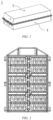
- the battery pack 1 of the present application comprises a battery case and a plurality of battery cells arranged in the battery case.
- the battery box comprises an upper box body 2 and a lower box body 3.
- the upper box body 2 can cover the lower box body 3 and a closed space for accommodating a plurality of battery cells, namely, a battery pack cavity is formed.
- the battery pack 1 comprises a battery pack cavity and a plurality of battery cells 5, 6 received in the battery pack cavity, where an interior space of the battery pack cavity can be divided into a first region R1 with a temperature change rate of K1 and a second region R2 with a temperature change rate of K2, where 0.066 ⁇ K1 ⁇ 0.131 and 0.034 ⁇ K2 ⁇ 0.066, K1 and K2 being expressed in °C/min;
- the plurality of battery cells 5, 6 comprises: at least one first battery cell 5 arranged in the first region R1; and at least one second battery cell 6 arranged in the second region R2; and the full discharge energies of the first battery cell 5 and the second battery cell 6 when standing at 25°C are E 1 and E 2 respectively and the full discharge energies of the first battery cell 5 and the second battery cell 6 when standing at -20°C are E 1 ' and E 2 ' respectively, where 1.05 ⁇ E 1 /E 2 ⁇ 1.45 and 0.97 ⁇ E 1
- the interior space of the battery pack cavity is divided into different regions, namely, a first region R1 with a temperature change rate of K1 and a second region R2 with a temperature change rate of K2, where 0.066°C/min ⁇ K1 ⁇ 0.131°C/min and 0.034°C/min ⁇ K2 ⁇ 0.066°C/min.
- the first region R1 with a large temperature change rate has a lower temperature in a low temperature environment, and the proportion of the energy that can be released by the first battery cell 5 arranged in the first region R1 in a low temperature environment relative to that which can be released under normal temperature is lower.
- the second region R2 with a small temperature change rate has a higher temperature in a low temperature environment, and the proportion of the energy that can be released by the second battery cell 6 arranged in the second region R2 in a low temperature environment relative to that can be released at normal temperature is higher than that of the first battery cell arranged in the first region.
- the first region R1 with a large temperature change rate is usually the outermost region in the interior space of the battery pack cavity, and the second region with a small temperature change rate is usually a region that is located at the inner side in the interior space of the battery pack cavity relative to the first region.
- the temperature change rate K in the interior space of the battery pack cavity is measured by the following method.
- a Jufu walk-in high and low temperature box (IWER-A2-40-TP-AR) is used.
- the battery pack is placed in the high and low temperature box at normal temperature, and then an ambient temperature sampling point are set 10 cm above the top cover of the battery pack, and temperature sensors are arranged at the grid intersections according to a space grid of 10cm x 10cm inside the battery pack, the distance between the temperature sensor and the bottom of the battery pack being half the distance from the bottom of the battery pack to the upper cover.
- the temperature sensor can be suspended by wires, or can be supported by thermally poor conductors such as paper shells.
- a high and low temperature box is set to decrease from room temperature (25°C) to 0°C, and the cooling rate of an ambient temperature sampling sensor is set to 0.205°C/min.
- a built-in temperature sensor detects the cooling rate throughout the battery pack, the time (unit: min) during which the temperature decreases from room temperature to 0°C at each location is measured, and an average cooling rate from room temperature to 0°C at each location is taken as the temperature change rate at that location (unit: °C/min).
- the full discharge energy of the battery cell when standing at 25°C and the full discharge energy when standing at -20°C are measured by a Xinwei power battery tester (model BTS-5V300A-4CH) using the following method.
- the battery cell is allowed to stand in an environment at 25°C for 120 min, and then charged to a rated upper limit voltage of the battery cell with a constant current and constant voltage at a charging current of 60A, with a charging cut-off current of 5A. It is allowed to stand for 30 min. Then, the battery is discharged to a rated lower limit voltage of the battery cell with a constant current at a current of 60A. At this time, the released energy displayed by the tester is the full discharge energy (unit: Wh) of the battery cell when standing at 25°C.
- the above-mentioned battery cell fully charged at 25°C is placed in an environment of -20°C, is allowed to stand for 120 min, and discharged to a rated lower limit voltage of the battery cell with a constant current at a current of 60A. After discharging is stopped, it is allowed to stand for 30 min. At this time, the released energy displayed by the tester is the full discharge energy (unit: Wh) of the battery cell when standing at -20°C.
- the ratio (%) of the full discharge energy when the battery cell is left standing at -20°C relative to the full discharge energy when standing at 25°C is called the low temperature energy retention rate (or low temperature capacity retention rate) of the battery cell
- the ratio (%) of the full discharge energy of the entire battery pack when standing at -20°C to the full discharge energy when standing at 25°C is called the total energy retention rate of the battery pack at -20°C (or total capacity retention rate of the battery pack at -20°C).
- the inventors have studied the relationship between the temperature change rate of the region where the battery cell is located and the low temperature energy retention rate of the battery cell. It is found that when the temperature change rate (cooling rate) of a certain region reaches or exceeds 0.066°C/min, the low temperature energy retention rate of the battery cell in this region during the same period is significantly smaller than the low temperature energy retention rate of the battery cell in a region with a small temperature change rate in the battery pack, and the overall low temperature energy retention rate of the battery pack is significantly reduced due to the cask effect.
- the temperature change rate of a certain region refers to the average temperature change rate when the temperature of the region decreases from room temperature 25°C to 0°C.
- an ordinary battery cell i.e., second battery cell 6
- a battery cell i.e., first battery cell 5
- a temperature change rate of 0.066°C/min or more i.e., first region R1
- first region R1 and second region R2 multiple locations are selected respectively, and the value of the temperature change rate K is measured by the above measurement method, and the upper limit of the temperature change rate of the first region R1 is obtained as 0.131°C/min, and the lower limit of the temperature change rate of the second region R2 is 0.034°C/min. Therefore, it is determined that the temperature change rate K1 of the first region R1 is in the range of 0.066 ⁇ K1 ⁇ 0.131, and the temperature change rate of the second region R2 is 0.034 ⁇ K2 ⁇ 0.066, where the unit is °C/min.
- the inventors have further conducted in-depth research on the relationship between E1, E2, E 1 ' and E 2 ' of the first battery cell 5 and the second battery cell 6 and the total energy retention rate of the battery pack at -20°C. It is found that when E 1 and E 2 of the first battery cell and the second battery cell satisfy the relationship of 1.05 ⁇ E 1 /E 2 ⁇ 1.45 , and E 1 ' and E 2 ' of the first battery cell and the second battery cell satisfy 0.97 ⁇ E 1 '/E 2 ' ⁇ 1.41 (where the unit of E 1 , E 2 , E 1 ' and E 2 is Wh), the energy that the first battery cell and the second battery cell can release at low temperature (discharge capacity at low temperature) is substantially identical, so that the cask effect of the battery pack can be avoided, the total energy retention rate of the battery pack at -20°C is excellent, and the overall endurance level of the battery pack at low temperature is improved.
- E1, E2, E 1 ' and E 2 ' satisfy 1.05 ⁇ E 1 /E 2 ⁇ 1.45, and 0.97 ⁇ E 1 '/E 2 ' ⁇ 1.41.
- E 1 '/E 1 is 70% to 95% and E 2 '/E 2 is 65% to 97%.
- the first battery cell 5 and the second battery cell 6 each have a relatively high low-temperature energy retention rate, and will not cause a cask effect that affects the overall energy exertion of the battery pack 1, and it is easy to maintain the excellent low temperature energy retention rate of the battery pack 1 as a whole.
- E 1 '/E 1 is 74% to 90% and E 2 '/E 2 is 70% to 85%.
- the first battery cell 5 and the second battery cell 6 each have a higher low-temperature energy retention rate, and the low-temperature energy retention rate of the first battery cell is higher than the low-temperature energy retention rate of the second battery cell, so that it is easy to keep the battery pack 1 with a more excellent low-temperature energy retention rate.
- the number of the first battery cells 5 in the first region R1 accounts for 10% or more of the total number of battery cells in the first region R1, optionally 30% or more, further optionally 50% or more, and more further optionally 80% or more.
- Arranging the first battery cell 5 with better low-temperature performance in the first region R1 with a lower temperature in a low temperature environment is an important technical means to achieve the objective of the present invention. If the ratio of the number of the first battery cells 5 in the first region R1 to the total number of battery cells in the first region R1 is less than 10%, the effect of the present invention may not be obtained. Therefore, the lower limit of this ratio is set to 10%. On the other hand, the higher the ratio, the more excellent the effect of the present invention. Therefore, only from the viewpoint of obtaining the effect of the present invention, the ratio is preferably 30% or more, more preferably 50% or more, and further preferably 80% or more. However, the cost of the first battery cell 5 with better low-temperature performance also increases accordingly. Therefore, if the factor of cost is also considered, the upper limit of the ratio above can be set according to the balance between the low-temperature energy retention rate and the cost.
- the number of the second battery cells 6 in the second region R2 accounts for 50% or more of the total number of battery cells in the second region R2, further optionally 80% or more.
- the number of the second battery cells 6 with ordinary low-temperature performance in the second region R2 can account for 50% or more of the total number of battery cells in the second region R2, reducing the number of first batteries in this region, it can avoid that the part of the energy of the first battery that exceeds the energy of the second battery at normal temperature cannot be exerted, resulting in a waste of energy density of the battery pack.
- the greater the battery difference the greater the difficulty of temperature monitoring and voltage equalization brought to the power management system, resulting in increased costs.
- the first region R1 is located at the outermost side in the interior space of the battery pack cavity, and the second region R2 is located at the inner side in the battery pack cavity relative to the first region R1.
- the outermost region in the interior space of the battery pack cavity is equivalent to the first region R1, with large temperature change rate, and a region that is located at the inner side in the interior space of the battery pack cavity relative to the outermost region is equivalent to the second region R2, with small temperature change rate.
- the objective of the present invention can be easily achieved by arranging the first battery cell 5 in the outermost region of the battery pack cavity and arranging the second battery cell 6 in the inner region thereof.
- the ratio of the volume of the first region R1 to the volume of the interior space of the battery pack cavity is 50% or less, optionally 40% or less, and further optionally 30% or less.
- the first battery cell 5 in the first region R1 has better low-temperature performance but higher cost, and thus, by allowing the ratio of the volume of the first region R1 to the volume of the interior space of the battery pack cavity to be within an appropriate range, significant increase in cost due to use of the first battery cell 5 can be suppressed.
- the first battery cell 5 and the second battery cell 6 are battery cells of the same chemical system with the same positive electrode material, negative electrode material and electrolyte.
- the first battery cell 5 and the second battery cell 6 are battery cells of the same chemical system with the same positive electrode material, negative electrode material and electrolyte
- the first battery cell 5 and the second battery cell 6 can be manufactured by adjusting the composition of at least one of the positive electrode material, the negative electrode material, and the electrolyte, and thus, the first battery cell 5 and the second battery cell 6 having different low-temperature performances can be easily manufactured.
- the first battery cell 5 and the second battery cell 6 are ternary batteries, lithium manganate batteries, lithium iron phosphate batteries, sodium ion batteries or lithium metal batteries.
- the effects of the present invention can be achieved as long as the first battery cell 5 and the second battery cell 6 in the battery pack 1 satisfy the range of the above-mentioned relationship of E 1 /E 2 and E 1 '/E 2 ', and the battery cells in the battery pack 1 can are existing batteries, such as ternary batteries, lithium manganate batteries, lithium iron phosphate batteries, sodium ion batteries, or lithium metal batteries, or batteries other than these batteries.
- existing lithium-ion batteries can be used as the first battery cell 5 and the second battery cell 6, so that the first battery cell 5 and the second battery cell 6 have a high degree of freedom of selection.
- the first battery cell 5 and the second battery cell 6 are battery cells of different chemical systems in which at least one of a positive electrode material, a negative electrode material and an electrolyte is different.
- Different chemical systems means that at least one of a positive electrode material, a negative electrode material and an electrolyte is different.
- a battery pack can be manufactured by combining existing battery cells of different chemical systems, and the degree of freedom in manufacturing the battery pack is high.
- the positive electrode active material of the first battery cell 5 is different from the positive electrode active material of the second battery cell 6, and the gram capacity of the positive electrode active material of the first battery cell 5 is 1.2 to 1.5 times the gram capacity of the positive electrode active material of the second battery cell 6.
- the gram capacity of the positive electrode active material of the battery cell can be obtained by the following method.
- the battery cell In an environment of 25°C, the battery cell is charged to a rated upper limit voltage with constant current and constant voltage at 0.33C, with a cut-off current of 0.05C. After standing for 30 min, it is discharged to a rated lower limit voltage at 0.33C, and the capacity released at this time is C1(Ah).
- the positive electrode plate of the battery is taken out, the electrolyte solution on the electrode plate is rinsed with DMC, and then the active material on the electrode plate is scraped off.
- the electrode plate is placed in an oven at 60°C for 12 hr, dried and then weighed to be n grams. Then the average capacity exertion of the battery is (C1 x 1000)/n, in mAh/g.
- the capacity of the first battery cell 5 is greater than the capacity of the second battery cell 6, and if the positive electrode active material of the first battery cell 5 is the same as the positive electrode active material of the second battery cell 6, the volume of the first battery cell 5 may be larger than the volume of the second battery cell 6.
- the capacity of the first battery cell 5 can be increased without significantly increasing the volume of the first battery cell 5, and the assembly of the battery pack 1 can be facilitated.
- the first battery cell 5 is a ternary battery
- the second battery cell 6 is a lithium manganate battery or a lithium iron phosphate battery.
- a ternary battery has better low-temperature performance compared with a lithium manganate battery or a lithium iron phosphate battery, and thus, the first battery cell 5 can use a ternary battery, and the second battery cell 6 can use a lithium manganate battery or a lithium iron phosphate battery.
- the battery pack 1 of the present application can be easily manufactured using existing battery cells.
- the battery cells (the first battery cell 5 and the second battery cell 6) used in the battery pack of the present application will be described in detail.
- the battery cell used in the battery pack of the present application is a secondary battery.
- a secondary battery comprises a positive electrode plate, a negative electrode plate, an electrolyte, and a separator.
- active ions are intercalated and de-intercalated back and forth between the positive electrode plate and the negative electrode plate.
- the electrolyte is located between the positive electrode plate and the negative electrode plate and functions for ionic conduction.
- the separator is provided between the positive electrode plate and the negative electrode plate, and mainly prevents the positive and negative electrodes from short-circuiting and enables ions to pass through.
- the positive electrode plate comprises a positive electrode current collector and a positive electrode film layer provided on at least one surface of the positive electrode current collector, the positive electrode film layer comprising a positive electrode active material.
- the positive electrode current collector has two surfaces opposite in its own thickness direction, and the positive electrode film layer is provided on either or both of the two opposite surfaces of the positive electrode current collector.
- the positive electrode current collector can be a metal foil or a composite current collector.
- a metal foil an aluminum foil can be used.
- the composite current collector may comprise a polymer material substrate and a metal layer formed on at least one surface of the polymer material substrate.
- the composite current collector can be formed by forming a metal material (aluminum, aluminum alloys, nickel, nickel alloys, titanium, titanium alloys, silver and silver alloys, etc.) on a polymer material base layer (such as polypropylene (PP), polyethylene terephthalate (PET), polybutylene terephthalate (PBT), polystyrene (PS), polyethylene (PE), etc.).
- PP polypropylene
- PET polyethylene terephthalate
- PBT polybutylene terephthalate
- PS polystyrene
- PE polyethylene
- the positive electrode active material can be a positive electrode active material known in the art for batteries.
- the positive electrode active material may include at least one of the following materials: lithium-containing phosphates of olivine structure, lithium transition metal oxides and their respective modified compounds.
- the present application is not limited to these materials, and other conventional materials that can be used as positive electrode active materials for batteries can also be used.
- These positive electrode active materials may be used alone or in combination of two or more.
- examples of lithium transition metal oxides may include, but are not limited to, at least one of lithium cobalt oxide (e.g. LiCoO 2 ), lithium nickel oxide (e.g. LiNiO 2 ), lithium manganese oxide (e.g.
- LiMnO 2 , LiMn 2 O 4 lithium nickel cobalt oxide, lithium manganese cobalt oxide, lithium nickel manganese oxide, lithium nickel cobalt manganese oxide (e.g. LiNi 1/3 Co 1/3 Mn 1/3 O 2 (also referred to as NCM 333 ), LiNi 0.5 Co 0.2 Mn 0.3 O 2 (also referred to as NCM 523 ), LiNi 0.5 Co 0.25 Mn 0.25 O 2 (also referred to as NCM 211 ), LiNi 0.6 Co 0.2 Mn 0.2 O 2 (also referred to as NCM 622 ), LiNi 0.8 Co 0.1 Mn 0.1 O 2 (also referred to as NCM 811 ), lithium nickel cobalt aluminum oxide (e.g.
- lithium-containing phosphates of olivine structure may include, but are not limited to, at least one of lithium iron phosphate (e.g. LiFePO 4 (also referred to as LFP)), lithium iron phosphate and carbon composites, lithium manganese phosphate (e.g. LiMnPO 4 ), lithium manganese phosphate and carbon composites, lithium iron manganese phosphate, and lithium iron manganese phosphate and carbon composites.
- LiFePO 4 also referred to as LFP
- LiMnPO 4 lithium manganese phosphate and carbon composites
- lithium iron manganese phosphate and carbon composites lithium iron manganese phosphate and carbon composites.
- the positive electrode film layer may optionally comprise a conductive agent.
- the conductive agent may include at least one of superconducting carbon, acetylene black, carbon black, Ketjen black, carbon dots, carbon nanotubes, graphene, and carbon nanofibers.
- the positive electrode plate can be prepared as follows: the above-mentioned components for preparing the positive electrode plate, such as positive electrode active material, conductive agent, binder and any other components, are dispersed in a solvent (e.g. N-methylpyrrolidone) to form a positive electrode slurry; and the positive electrode slurry is coated onto a positive electrode current collector, and is then subjected to procedures such as drying and cold pressing, so as to obtain the positive electrode plate.
- a solvent e.g. N-methylpyrrolidone
- the negative electrode plate comprises a negative electrode current collector and a negative electrode film layer provided on at least one surface of the negative electrode current collector, the negative electrode film layer comprising a negative electrode active material.
- the negative electrode current collector has two surfaces opposite in its own thickness direction, and the negative electrode film layer is provided on either or both of the two opposite surfaces of the negative electrode current collector.
- the negative electrode current collector can be a metal foil or a composite current collector.
- a metal foil a copper foil can be used.
- the composite current collector may comprise a polymer material substrate and a metal layer formed on at least one surface of the polymer material substrate.
- the composite current collector can be formed by forming metal materials (copper, copper alloys, nickel, nickel alloys, titanium, titanium alloys, silver and silver alloys, etc.) on the polymer material base layer (such as polypropylene (PP), polyethylene terephthalate (PET), polybutylene terephthalate (PBT), polystyrene (PS), polyethylene (PE), etc.).
- PP polypropylene
- PET polyethylene terephthalate
- PBT polybutylene terephthalate
- PS polystyrene
- PE polyethylene
- the negative electrode active material can be a negative electrode active material known in the art for batteries.
- the negative electrode active material may include at least one of the following materials: artificial graphite, natural graphite, soft carbon, hard carbon, a silicon-based material, a tin-based material and lithium titanate, etc.
- the silicon-based material may be selected from at least one of elemental silicon, silicon oxides, silicon carbon composites, silicon nitrogen composites and silicon alloys.
- the tin-based material may be selected from at least one of elemental tin, tin oxides, and tin alloys.
- the present application is not limited to these materials, and other conventional materials that can be used as negative electrode active materials for batteries can also be used. These negative electrode active materials may be used alone or in combination of two or more.
- the negative electrode film layer may optionally comprise a binder.
- the binder may be selected from at least one of a butadiene styrene rubber (SBR), polyacrylic acid (PAA), sodium polyacrylate (PAAS), polyacrylamide (PAM), polyvinyl alcohol (PVA), sodium alginate (SA), polymethacrylic acid (PMAA) and carboxymethyl chitosan (CMCS).
- SBR butadiene styrene rubber
- PAA polyacrylic acid
- PAAS sodium polyacrylate
- PAM polyacrylamide
- PVA polyvinyl alcohol
- SA sodium alginate
- PMAA polymethacrylic acid
- CMCS carboxymethyl chitosan
- the negative electrode film layer may optionally comprise a conductive agent.
- the conductive agent may be selected from at least one of superconductive carbon, acetylene black, carbon black, ketjenblack, carbon dots, carbon nanotubes, graphene, and carbon nanofibers.
- the negative electrode film layer may optionally comprise other auxiliary agents, such as thickener (e.g. sodium carboxymethyl cellulose (CMC-Na)) and the like.
- thickener e.g. sodium carboxymethyl cellulose (CMC-Na)
- CMC-Na sodium carboxymethyl cellulose
- the negative electrode plate can be prepared as follows: the above-mentioned components for preparing the negative electrode plate, such as negative electrode active material, conductive agent, binder and any other components, are dispersed in a solvent (e.g. deionized water) to form a negative electrode slurry; and the negative electrode slurry is coated onto a negative electrode current collector, and is then subjected to procedures such as drying and cold pressing, so as to obtain the negative electrode plate.
- a solvent e.g. deionized water
- the electrolyte is located between the positive electrode plate and the negative electrode plate and functions for ionic conduction.
- the electrolyte can be selected according to the requirements.
- the electrolyte may be liquid, gel or all solid.
- an electrolyte solution is used as the electrolyte.
- the electrolyte solution comprises an electrolyte salt and a solvent.
- the electrolyte salt may be selected from at least one of lithium hexafluorophosphate, lithium tetrafluoroborate, lithium perchlorate, lithium hexafluoroarsenate, lithium bisfluorosulfonimide, lithium bistrifluoromethanesulfonimide, lithium trifluoromethanesulfonate, lithium difluorophosphate, lithium difluorooxalate borate, lithium dioxalate borate, lithium difluorodioxalate phosphate and lithium tetrafluorooxalate phosphate.
- the solvent may be selected from at least one of ethylene carbonate, propylene carbonate, ethyl methyl carbonate, diethyl carbonate, dimethyl carbonate, dipropyl carbonate, methyl propyl carbonate, ethyl propyl carbonate, butylene carbonate, fluoroethylene carbonate, methyl formate, methyl acetate, ethyl acetate, propyl acetate, methyl propionate, ethyl propionate, propyl propionate, methyl butyrate, ethyl butyrate, 1,4-butyrolactone, sulfolane, dimethyl sulfone, ethyl methyl sulfone, and diethyl sulfone.
- the electrolyte solution may optionally comprise an additive.
- the additive can include a negative electrode film-forming additive, a positive electrode film-forming additive, and also an additive that can improve certain performances of the battery, such as an additive that improve the overcharge performance of the battery, or an additive that improve the high temperature performance or low-temperature performance of the battery.
- the secondary battery further comprises a separator.
- the type of the separator is not particularly limited in the present application, and any well known porous-structure separator with good chemical stability and mechanical stability can be selected.
- the material of the separator can be selected from at least one of glass fibers, a non-woven, polyethylene, polypropylene and polyvinylidene fluoride.
- the separator may be a single-layer film and also a multi-layer composite film, and is not limited particularly.
- the separator is a multi-layer composite film, the materials in the respective layers may be same or different, which is not limited particularly.
- an electrode assembly may be formed by a positive electrode plate, a negative electrode plate and a separator by a winding process or a laminating process.
- the secondary battery may comprise an outer package.
- the outer package is used to encapsulate the above electrode assembly and electrolyte.
- the outer package of the secondary battery can be a hard shell, for example, a hard plastic shell, an aluminum shell, a steel shell, etc.
- the outer package of the secondary battery can also be a soft bag, such as a pouch-type soft bag.
- the material of the soft package may be plastics, and the examples of plastics may include polypropylene, polybutylene terephthalate, and polybutylene succinate, etc.
- Fig. 4 is a first battery cell 5 of a square structure as an example (here, the first battery cell 5 is taken as an example for description, and the same is true for the second battery cell 6).
- the outer package may comprise a housing 51 and a cover plate 53.
- the housing 51 may comprise a bottom plate and side plates connected to the bottom plate, and the bottom plate and the side plates enclose and form an accommodating cavity.
- the housing 51 has an opening in communication with the accommodating cavity, and the cover plate 53 can cover the opening to close the accommodating cavity.
- the positive electrode plate, the negative electrode plate and the separator can form an electrode assembly 52 by a winding process or a lamination process.
- the electrode assembly 52 is encapsulated in the accommodating cavity.
- the electrolyte solution is infiltrated into the electrode assembly 52.
- the number of the electrode assemblies 52 contained in the first battery cell 5 may be one or more, and may be selected by those skilled in the art according to actual requirements.
- At least one first battery cell 5 and at least one second battery cell 6 can be assembled into a battery pack 1, and the specific numbers of the first battery cells 5 and the second battery cells 6 contained in the battery pack 1 can be selected according to the application and capacity of the battery pack.
- the present application also provides an power consuming device comprising the battery pack of the present application.
- the battery pack may be used as a power supply of the power consuming device, or as an energy storage unit of the power consuming device.
- the power consuming device may include a mobile device (e.g., a mobile phone, a laptop computer, etc.), an electric vehicle (e.g., a pure electric vehicle, a hybrid electric vehicle, a plug-in hybrid electric vehicle, an electric bicycle, an electric scooter, an electric golf cart, an electric truck), an electric train, ship, and satellite, an energy storage system, and the like, but are not limited thereto.
- the battery cell or battery pack can be selected according to the usage requirements thereof.
- Fig. 6 shows a power consuming device as an example.
- the power consuming device may be a pure electric vehicle, a hybrid electric vehicle, a plug-in hybrid electric vehicle or the like.
- the battery pack of the present application can be used.
- a positive active material LiNi 0.55 Co 0.05 Mn 0.4 O 2 , superconducting carbon black SP as a conductive agent and polyvinylidene fluoride (PVDF) as a binder were dispersed in N-methylpyrrolidone (NMP) as a solvent in a mass ratio of 96:1.2:2.8 and mixed uniformly to obtain a positive electrode slurry; and the positive electrode slurry was evenly coated onto a positive electrode current collector aluminum foil, and was subjected to drying, cold pressing, slitting and cutting, so as to obtain the positive electrode plate.
- NMP N-methylpyrrolidone
- a negative electrode active material graphite, superconducting carbon black SP as a conductive agent, SBR as a binder, and CMC-Na as a thickener were dispersed in deionized water as a solvent in a mass ratio of 96:1:1:2 and mixed uniformly to obtain a negative electrode slurry; and the negative electrode slurry was evenly coated onto a negative electrode current collector copper foil, and was subjected to drying, cold pressing, slitting and cutting, so as to obtain the negative electrode plate.
- Polyethylene film is selected as the isolation film.
- Ethylene carbonate (EC), dimethyl carbonate (DMC), and diethyl carbonate (DEC) are mixed in a volume ratio of 1:1:1 into an organic solvent, and then the fully dried lithium salt LiPF 6 was dissolved in the mixed organic solvent, so as to prepare an electrolyte solution with a concentration of 1 mol/L.
- the above-mentioned positive electrode plate, separator, and negative electrode plate were stacked in sequence, such that the separator is located between the positive electrode plate and the negative electrode plate to play a role of isolation, and then winding was performed to obtain a bare bell; and the bare cell was placed in an outer packaging case, dried and then injected with the electrolyte solution, and was subjected to procedures such as vacuum packaging, standing, forming and shaping, so as to obtain a first battery cell I-1.
- a first battery cell I-2 was obtained in the same manner as in Preparation Example I-1, except that superconducting carbon black SP and carbon nanotube (CNT) were used as the conductive agent and the mass ratio of the positive electrode active material, superconducting carbon black SP, carbon nanotubes and binder was 96:2.1:0.2:1.7.
- superconducting carbon black SP and carbon nanotube (CNT) were used as the conductive agent and the mass ratio of the positive electrode active material, superconducting carbon black SP, carbon nanotubes and binder was 96:2.1:0.2:1.7.
- a first battery cell I-3 was obtained in the same manner as in Preparation Example I-1, except that superconducting carbon black SP and carbon nanotube (CNT) were used as the conductive agent and the mass ratio of the positive electrode active material, superconducting carbon black SP, carbon nanotubes and binder was 96:1.5:0.8:1.7.
- superconducting carbon black SP and carbon nanotube (CNT) were used as the conductive agent and the mass ratio of the positive electrode active material, superconducting carbon black SP, carbon nanotubes and binder was 96:1.5:0.8:1.7.
- a first battery cell I-4 was obtained in the same manner as in Preparation Example I-1, except that LiNi 0.55 Co 0.12 Mn 0.4 O 2 was used as positive electrode active material, superconducting carbon black SP and graphene were used as the conductive agent and the mass ratio of the positive electrode active material, superconducting carbon black SP, graphene and binder was 96:1:1:2.
- a first battery cell I-5 was obtained in the same manner as in Preparation Example I-1, except that LiNi 0.55 Co 0.12 Mn 0.4 O 2 was used as positive electrode active material, superconducting carbon black SP and graphene were used as the conductive agent and the mass ratio of the positive electrode active material, superconducting carbon black SP, graphene and binder was 96:1:0.4:2.6.
- a first battery cell I-6 was obtained in the same manner as in Preparation Example I-1, except that the mass ratio of the positive electrode active material, superconducting carbon black SP and binder was 96:1.3:2.7.
- a first battery cell I-8 was obtained in the same manner as in Preparation Example I-1, except that LiNi 0.55 Co 0.12 Mn 0.4 O 2 was used as positive electrode active material, superconducting carbon black SP and graphene were used as the conductive agent and the mass ratio of the positive electrode active material, superconducting carbon black SP, graphene and binder was 96:1:0.9:2.1.
- a first battery cell I-9 was obtained in the same manner as in Preparation Example I-1, except that the mass ratio of the positive electrode active material, superconducting carbon black SP and binder was 96:1:3.
- a first battery cell I-10 was obtained in the same manner as in Preparation Example I-1, except that the mass ratio of the positive electrode active material, superconducting carbon black SP and binder was 96:1.1:2.9.
- a first battery cell I-11 was obtained in the same manner as in Preparation Example I-1, except that the mass ratio of the positive electrode active material, superconducting carbon black SP and binder was 96:1.4:2.6.
- a second battery cell II-1 was obtained in the same manner as in Preparation Example I-1, except that lithium iron phosphate (LFP) was used as the positive electrode active material and the mass ratio of the positive electrode active material, superconducting carbon black SP and binder was 96:1.5:2.5.
- LFP lithium iron phosphate
- a second battery cell II-2 was obtained in the same manner as in Preparation Example I-1, except that lithium iron phosphate (LFP) was used as the positive electrode active material and the mass ratio of the positive electrode active material, superconducting carbon black SP and binder was 96:1.2:2.8.
- LFP lithium iron phosphate
- a second battery cell II-3 was obtained in the same manner as in Preparation Example I-1, except that lithium iron phosphate (LFP) was used as the positive electrode active material and the mass ratio of the positive electrode active material, superconducting carbon black SP and binder was 96:1.6:2.4.
- LFP lithium iron phosphate
- a second battery cell II-4 was obtained in the same manner as in Preparation Example I-1, except that Na 3 V 2 (PO 4 ) 2 O 2 F was used as the positive electrode active material, carbon nanotubes (CNT) were used as the conductive agent and the mass ratio of the positive electrode active material, carbon nanotubes and binder was 96:2.2:1.8.
- a second battery cell II-5 was obtained in the same manner as in Preparation Example I-1, except that lithium iron phosphate (LFP) was used as the positive electrode active material, superconducting carbon black SP and carbon nanotube (CNT) were used as the conductive agent and the mass ratio of the positive electrode active material, superconducting carbon black SP, carbon nanotubes and binder was 96:1:1.3:1.7.
- LFP lithium iron phosphate
- CNT carbon nanotube
- a second battery cell II-6 was obtained in the same manner as in Preparation Example I-1, except that lithium iron phosphate (LFP) was used as the positive electrode active material, superconducting carbon black SP and carbon nanotube (CNT) were used as the conductive agent and the mass ratio of the positive electrode active material, superconducting carbon black SP, carbon nanotubes and binder was 96:1:1:2.
- LFP lithium iron phosphate
- CNT carbon nanotube
- a second battery cell II-7 was obtained in the same manner as in Preparation Example I-1, except that LiMn 2 O 4 was used as the positive electrode active material, superconducting carbon black SP and carbon nanotube (CNT) were used as the conductive agent and the mass ratio of the positive electrode active material, superconducting carbon black SP, carbon nanotubes and binder was 96:1:0.8:2.2.
- a second battery cell II-9 was obtained in the same manner as in Preparation Example I-1, except that lithium iron phosphate (LFP) was used as the positive electrode active material and the mass ratio of the positive electrode active material, superconducting carbon black SP and binder was 96:0.5:3.5.
- LFP lithium iron phosphate
- the first battery cell I-1 was arranged in a first region R1, and the second battery cell II-1 was arranged in a second region R2, and a battery pack was assembled.
- the number of the first battery cells I-1 in the first region R1 accounted for 100% of the total number of battery cells in the first region R1
- the number of the second battery cells II-1 in the second region R2 accounted for 100% of the total number of battery cells in the second region R2.
- a battery pack was assembled in the same manner as in Example 1, except that the first battery cell I-3 was used in place of the first battery cell I-1 and the second battery cell II-8 was used in place of the second battery cell II-1.
- a battery pack was assembled in the same manner as in Example 1, except that the first battery cell I-6 was used in place of the first battery cell I-1 and the second battery cell II-2 was used in place of the second battery cell II-1.
- a battery pack was assembled in the same manner as in Example 1, except that the first battery cell I-7 was used in place of the first battery cell I-1 and the second battery cell II-4 was used in place of the second battery cell II-1.
- a battery pack was assembled in the same manner as in Example 1, except that the first battery cell I-8 was used in place of the first battery cell I-1 and the second battery cell II-5 was used in place of the second battery cell II-1.
- a battery pack was assembled in the same manner as in Example 1, except that the first battery cell II-4 was used in place of the first battery cell I-1 and the second battery cell II-6 was used in place of the second battery cell II-1.
- a battery pack was assembled in the same manner as in Example 1, except that the first battery cell I-6 was used in place of the first battery cell I-1 and the second battery cell II-7 was used in place of the second battery cell II-1.
- a battery pack was assembled in the same manner as in Example 1, except that the first battery cell I-2 was used in place of the first battery cell I-1, the second battery cell II-3 was used in place of the second battery cell II-1, and the number of the first battery cells I-2 in the first region R1 accounted for 10% of the total number of battery cells in the first region R1 (the remaining 90% of the battery cells in the first region R1 were the second battery cells II-3).
- a battery pack was assembled in the same manner as in Example 12, except that the number of the first battery cells I-2 in the first region R1 accounted for 30% of the total number of battery cells in the first region R1 (the remaining 70% of the battery cells in the first region R1 were the second battery cells II-3).
- a battery pack was assembled in the same manner as in Example 12, except that the number of the first battery cells I-2 in the first region R1 accounted for 40% of the total number of battery cells in the first region R1 (the remaining 60% of the battery cells in the first region R1 were the second battery cells II-3).
- a battery pack was assembled in the same manner as in Example 12, except that the number of the first battery cells I-2 in the first region R1 accounted for 60% of the total number of battery cells in the first region R1 (the remaining 40% of the battery cells in the first region R1 were the second battery cells II-3).
- a battery pack was assembled in the same manner as in Example 12, except that the number of the first battery cells I-2 in the first region R1 accounted for 80% of the total number of battery cells in the first region R1 (the remaining 20% of the battery cells in the first region R1 were the second battery cells II-3).
- a battery pack was assembled in the same manner as in Example 12, except that the number of the first battery cells I-2 in the first region R1 accounted for 100% of the total number of battery cells in the first region R1.
- a battery pack was assembled in the same manner as in Example 1, except that the first battery cell I-9 was used in place of the first battery cell I-1.
- a battery pack was assembled in the same manner as in Example 1, except that the first battery cell I-11 was used in place of the first battery cell I-1 and the second battery cell II-10 was used in place of the second battery cell II-1.
- a battery pack was assembled in the same manner as in Example 1, except that the first battery cell I-10 was used in place of the first battery cell I-1 and the second battery cell II-11 was used in place of the second battery cell II-1.
- a battery pack was assembled in the same manner as in Example 1, except that the first battery cell I-5 was used in place of the first battery cell I-1 and the second battery cell II-9 was used in place of the second battery cell II-1.
- a battery pack was assembled in the same manner as in Example 12, except that the number of the first battery cells I-2 in the first region R1 accounted for 8% of the total number of battery cells in the first region R1 (the remaining 92% of the battery cells in the first region R1 were the second battery cells II-3).
- total discharge energies (KWh) at -20°C were respectively measured by a Xinwei power battery tester (model BTS-5V300A-4CH), and the total discharge energy (KWh) at -20°C was divided by the total discharge energy of the battery pack at 25°C, so as to calculate the total energy retention rate (%) of the battery pack at -20°C.
- the total discharge energy (KWh) at -20°C and total energy retention rate (%) at -20°C of the battery packs of Examples 1 to 17 and Comparative Examples 1 to 5 are shown in Table 3 and Table 4 together with the first battery cell and the second battery cell used in each battery pack and their relevant parameters.
- Table 3 Composition and performance parameters of battery packs of examples and comparative examples Battery pack First battery cell Second battery cell E 1 (Wh ) E 2 (Wh ) E 1 ' (Wh ) E 2 ' (Wh ) E 1 '/E 2' E 1 '/E 2' Total discharg e energy of battery pack at - 20°C (KWh) Total energy retention rate of battery pack at - 20°C Exampl e 1 I-1 II-1 735 676 551.
Landscapes
- Chemical & Material Sciences (AREA)
- Chemical Kinetics & Catalysis (AREA)
- Electrochemistry (AREA)
- General Chemical & Material Sciences (AREA)
- Engineering & Computer Science (AREA)
- Manufacturing & Machinery (AREA)
- Inorganic Chemistry (AREA)
- Microelectronics & Electronic Packaging (AREA)
- Materials Engineering (AREA)
- Crystallography & Structural Chemistry (AREA)
- Battery Mounting, Suspending (AREA)
Claims (13)
- Batteriesatz (1), der einen Batteriesatz-Hohlraum und mehrere Batteriezellen (5, 6) aufweist, die in dem Batteriesatz-Hohlraum aufgenommen sind,wobei ein Innenraum des Batteriesatz-Hohlraums in einen ersten Bereich (R1) mit einer Temperaturänderungsrate von K1 und einen zweiten Bereich (R2) mit einer Temperaturänderungsrate von K2 unterteilt ist, wobei 0,066 ≤ K1 ≤ 0,131 und 0,034 ≤ K2 < 0,066, wobei K1 und K2 in °C/min ausgedrückt werden;die mehreren Batteriezellen (5, 6) umfassen: mindestens eine erste Batteriezelle (5), die in dem ersten Bereich (R1) angeordnet ist; und mindestens eine zweite Batteriezelle, die in dem zweiten Bereich (R2) angeordnet ist;und die Vollentladungsenergie der ersten Batteriezelle (5) und der zweiten Batteriezelle (6) bei einer Standtemperatur von 25 °C E1 beziehungsweise E2 ist und die Vollentladungsenergie der ersten Batteriezelle (5) und der zweiten Batteriezelle (6) bei einer Standtemperatur von -20 °C E1' beziehungsweise E2' ist, wobei E1, E2, E1' und E2' in Wh ausgedrückt werden, wobei 1,05 ≤ E1/E2 ≤ 1,45 und 0,97 ≤ E1'/E2' ≤ 1,41.
- Batteriesatz (1) nach Anspruch 1, wobei E1'/E1 70 % bis 95 % beträgt und E2'/E2 65 % bis 97 % beträgt.
- Batteriesatz (1) nach Anspruch 2, wobei 74 % bis 90 % beträgt und E2'/E2 70 % bis 85 % ist.
- Batteriesatz (1) nach einem der Ansprüche 1 bis 3, wobei
die Anzahl der ersten Batteriezellen (5) in dem ersten Bereich (R1) 10 % oder mehr der Gesamtanzahl von Batteriezellen (5, 6) in dem ersten Bereich (R1) ausmacht, wahlweise 30 % oder mehr, ferner wahlweise 50 % oder mehr und noch ferner wahlweise 80 % oder mehr. - Batteriesatz (1) nach einem der Ansprüche 1 bis 4, wobei
die Anzahl der zweiten Batteriezellen (6) in dem zweiten Bereich (R2) 50 % oder mehr der Gesamtanzahl von Batteriezellen (5, 6) in dem zweiten Bereich (R2) ausmacht, ferner wahlweise 80 % oder mehr. - Batteriesatz (1) nach einem der Ansprüche 1 bis 5, wobei
der erste Bereich (R1) sich an der äußersten Seite im Innenraum des Batteriesatz-Hohlraums befindet und der zweite Bereich (R2) sich im Verhältnis zu dem ersten Bereich (R1) an der inneren Seite im Batteriesatz-Hohlraum befindet. - Batteriesatz (1) nach einem der Ansprüche 1 bis 6, wobei
das Verhältnis des Volumens des ersten Bereichs (R1) zu dem Volumen des Innenraums des Batteriesatz-Hohlraums 50 % oder weniger beträgt, wahlweise 40 % oder weniger und ferner wahlweise 30 % oder weniger. - Batteriesatz (1) nach einem der Ansprüche 1 bis 7, wobei
die erste Batteriezelle (5) und die zweite Batteriezelle (6) Batteriezellen (5, 6) des gleichen chemischen Systems mit dem gleichen Positivelektrodenmaterial, Negativelektrodenmaterial und Elektrolyt sind. - Batteriesatz (1) nach Anspruch 8, wobei
die erste Batteriezelle (5) und die zweite Batteriezelle (6) ternäre Batterien, Lithiummanganat-Batterien, Lithiumeisenphosphat-Batterien, Natrium-Ionen-Batterien oder Lithiummetall-Batterien sind. - Batteriesatz (1) nach einem der Ansprüche 1 bis 7, wobei
die erste Batteriezelle (5) und die zweite Batteriezelle (6) Batteriezellen (5, 6) von unterschiedlichen chemischen Systemen sind, bei denen ein Positivelektrodenmaterial, ein Negativelektrodenmaterial und/oder ein Elektrolyt verschieden ist. - Batteriesatz (1) nach Anspruch 10, wobei
das Positivelektroden-Aktivmaterial der ersten Batteriezelle (5) verschieden von dem Positivelektroden-Aktivmaterial der zweiten Batteriezelle (6) ist und die Gramm-Kapazität des Positivelektroden-Aktivmaterials der ersten Batteriezelle (5) das 1,2 bis 1,5-Fache der Gramm-Kapazität des Positivelektroden-Aktivmaterials der zweiten Batteriezelle (6) beträgt. - Batteriesatz (1) nach Anspruch 10 oder 11, wobei
die erste Batteriezelle (5) eine ternäre Batterie ist und die zweite Batteriezelle (6) eine Lithiummanganat-Batterie oder eine Lithiumeisenphosphat-Batterie ist. - Stromverbrauchsvorrichtung mit dem Batteriesatz (1) nach einem der Ansprüche 1 bis 12.
Applications Claiming Priority (1)
| Application Number | Priority Date | Filing Date | Title |
|---|---|---|---|
| PCT/CN2021/119468 WO2023039913A1 (zh) | 2021-09-18 | 2021-09-18 | 电池包和用电装置 |
Publications (4)
| Publication Number | Publication Date |
|---|---|
| EP4187684A1 EP4187684A1 (de) | 2023-05-31 |
| EP4187684A4 EP4187684A4 (de) | 2023-11-15 |
| EP4187684C0 EP4187684C0 (de) | 2025-05-28 |
| EP4187684B1 true EP4187684B1 (de) | 2025-05-28 |
Family
ID=85573074
Family Applications (1)
| Application Number | Title | Priority Date | Filing Date |
|---|---|---|---|
| EP21921633.0A Active EP4187684B1 (de) | 2021-09-18 | 2021-09-18 | Batteriesatz |
Country Status (5)
| Country | Link |
|---|---|
| US (1) | US11799161B2 (de) |
| EP (1) | EP4187684B1 (de) |
| CN (1) | CN116848708A (de) |
| ES (1) | ES3037818T3 (de) |
| WO (1) | WO2023039913A1 (de) |
Families Citing this family (1)
| Publication number | Priority date | Publication date | Assignee | Title |
|---|---|---|---|---|
| CN118610660B (zh) * | 2024-08-09 | 2024-11-15 | 比亚迪股份有限公司 | 温度控制方法、温度控制系统及用电设备 |
Family Cites Families (9)
| Publication number | Priority date | Publication date | Assignee | Title |
|---|---|---|---|---|
| US8021773B1 (en) * | 2007-03-20 | 2011-09-20 | Mphase Technologies, Inc. | Battery system |
| JP2013211980A (ja) * | 2012-03-30 | 2013-10-10 | Hitachi Koki Co Ltd | 電動工具、電池パック |
| CN103326084B (zh) * | 2013-06-04 | 2016-01-13 | 哈尔滨圣为技术有限公司 | 电池组温度控制装置及电池组温度控制方法 |
| CN105790364A (zh) * | 2016-04-18 | 2016-07-20 | 洛阳尹太科智能科技有限公司 | 内燃机车辆电气系统及其供电方法 |
| CN107275714B (zh) * | 2017-06-27 | 2018-03-09 | 周舜 | 一种锂离子电池管理系统 |
| US10661679B2 (en) * | 2018-10-26 | 2020-05-26 | Premergy, Inc. | Multiple chemistry battery systems for electric vehicles |
| CN114586255B (zh) * | 2019-10-15 | 2026-03-20 | 华为技术有限公司 | 用于优化充电和冷使用的多个电池 |
| CN111446488B (zh) * | 2020-04-30 | 2025-02-18 | 宁德时代新能源科技股份有限公司 | 一种二次电池及其装置 |
| EP4047711A4 (de) * | 2020-12-24 | 2022-11-30 | Contemporary Amperex Technology Co., Limited | Batteriemodul, batteriepack, elektronisches gerät sowie verfahren zur herstellung eines batteriemoduls und herstellungsverfahren |
-
2021
- 2021-09-18 WO PCT/CN2021/119468 patent/WO2023039913A1/zh not_active Ceased
- 2021-09-18 CN CN202180092708.2A patent/CN116848708A/zh active Pending
- 2021-09-18 ES ES21921633T patent/ES3037818T3/es active Active
- 2021-09-18 EP EP21921633.0A patent/EP4187684B1/de active Active
-
2022
- 2022-08-09 US US17/818,407 patent/US11799161B2/en active Active
Also Published As
| Publication number | Publication date |
|---|---|
| EP4187684A1 (de) | 2023-05-31 |
| EP4187684A4 (de) | 2023-11-15 |
| US11799161B2 (en) | 2023-10-24 |
| EP4187684C0 (de) | 2025-05-28 |
| ES3037818T3 (en) | 2025-10-07 |
| US20230086688A1 (en) | 2023-03-23 |
| CN116848708A (zh) | 2023-10-03 |
| WO2023039913A1 (zh) | 2023-03-23 |
Similar Documents
| Publication | Publication Date | Title |
|---|---|---|
| KR102502618B1 (ko) | 이차 전지, 이차 전지를 포함하는 전지 모듈, 전지 팩 및 장치 | |
| EP4310983A1 (de) | Batteriepack und elektrische vorrichtung | |
| EP4246647A1 (de) | Elektrolyt, sekundärbatterie und elektrische vorrichtung | |
| CN115832290A (zh) | 负极活性材料及其制备方法、负极极片、二次电池、电池模块、电池包和用电装置 | |
| EP4528905A1 (de) | Trennfolie und herstellungsverfahren dafür, sekundärbatterie und elektrische vorrichtung | |
| EP4297139A1 (de) | Sekundärbatterie, batteriemodul, batteriepack und elektrische vorrichtung | |
| EP4228043A1 (de) | Batteriegruppe, batteriepack, elektrische vorrichtung, herstellungsverfahren und herstellungsvorrichtung für batteriegruppe und steuerungsverfahren für batteriegruppe | |
| US20240145793A1 (en) | Secondary Battery, Battery Module, Battery Pack and Power Consuming Device | |
| CN121726337A (zh) | 负极极片、二次电池和用电装置 | |
| JP7674463B2 (ja) | 負極極板、二次電池、電池モジュール、電池パックと電力消費装置 | |
| EP4258383A1 (de) | Positivelektrodenfolie, sekundärbatterie, batteriemodul, batteriepack, elektrische vorrichtung und verfahren zum ausgleichen der internen spannungsdifferenz einer batterie | |
| EP4187684B1 (de) | Batteriesatz | |
| EP4195349A1 (de) | Sekundärbatterie | |
| WO2023141972A1 (zh) | 正极极片及包含所述极片的锂离子电池 | |
| US11901575B2 (en) | Battery pack and power consuming device | |
| US20240186479A1 (en) | Negative electrode plate, secondary battery, battery module, battery pack, and electric apparatus | |
| WO2024065764A1 (zh) | 负极极片及其制备方法、二次电池和用电装置 | |
| WO2024026654A1 (zh) | 负极极片、二次电池及用电装置 | |
| US20250336983A1 (en) | Current collector and preparation method therefor, secondary battery, and electric device | |
| US20240258602A1 (en) | Battery pack and power consuming device | |
| EP4510265A1 (de) | Elektrolytlösung, sekundärbatterie, batteriemodul, batteriepack und elektrische vorrichtung | |
| EP4564447A1 (de) | Batteriezelle und herstellungsverfahren dafür, sekundärbatterie und elektrische vorrichtung | |
| US20250357536A1 (en) | Secondary battery and preparation method therefor, and electric device | |
| US20260011720A1 (en) | Positive electrode plate, secondary battery and electrical apparatus | |
| EP4604203A1 (de) | Positivelektrodenfolie und herstellungsverfahren dafür, batteriezelle, batterie und elektrische vorrichtung |
Legal Events
| Date | Code | Title | Description |
|---|---|---|---|
| STAA | Information on the status of an ep patent application or granted ep patent |
Free format text: STATUS: UNKNOWN |
|
| STAA | Information on the status of an ep patent application or granted ep patent |
Free format text: STATUS: THE INTERNATIONAL PUBLICATION HAS BEEN MADE |
|
| PUAI | Public reference made under article 153(3) epc to a published international application that has entered the european phase |
Free format text: ORIGINAL CODE: 0009012 |
|
| STAA | Information on the status of an ep patent application or granted ep patent |
Free format text: STATUS: REQUEST FOR EXAMINATION WAS MADE |
|
| 17P | Request for examination filed |
Effective date: 20220909 |
|
| AK | Designated contracting states |
Kind code of ref document: A1 Designated state(s): AL AT BE BG CH CY CZ DE DK EE ES FI FR GB GR HR HU IE IS IT LI LT LU LV MC MK MT NL NO PL PT RO RS SE SI SK SM TR |
|
| A4 | Supplementary search report drawn up and despatched |
Effective date: 20231018 |
|
| RIC1 | Information provided on ipc code assigned before grant |
Ipc: H01M 50/211 20210101ALI20231012BHEP Ipc: H01M 50/267 20210101ALI20231012BHEP Ipc: H01M 50/213 20210101ALI20231012BHEP Ipc: H01M 50/209 20210101ALI20231012BHEP Ipc: H01M 4/58 20100101ALI20231012BHEP Ipc: H01M 4/525 20100101ALI20231012BHEP Ipc: H01M 4/505 20100101ALI20231012BHEP Ipc: H01M 10/643 20140101ALI20231012BHEP Ipc: H01M 10/617 20140101ALI20231012BHEP Ipc: H01M 10/613 20140101ALI20231012BHEP Ipc: H01M 10/48 20060101ALI20231012BHEP Ipc: H01M 10/44 20060101ALI20231012BHEP Ipc: H01M 10/42 20060101ALI20231012BHEP Ipc: H01M 10/0525 20100101ALI20231012BHEP Ipc: H01M 50/112 20210101ALI20231012BHEP Ipc: H01M 50/10 20210101AFI20231012BHEP |
|
| STAA | Information on the status of an ep patent application or granted ep patent |
Free format text: STATUS: EXAMINATION IS IN PROGRESS |
|
| 17Q | First examination report despatched |
Effective date: 20240611 |
|
| RAP1 | Party data changed (applicant data changed or rights of an application transferred) |
Owner name: CONTEMPORARY AMPEREX TECHNOLOGY(HONG KONG) LIMITED |
|
| DAV | Request for validation of the european patent (deleted) | ||
| DAX | Request for extension of the european patent (deleted) | ||
| GRAP | Despatch of communication of intention to grant a patent |
Free format text: ORIGINAL CODE: EPIDOSNIGR1 |
|
| STAA | Information on the status of an ep patent application or granted ep patent |
Free format text: STATUS: GRANT OF PATENT IS INTENDED |
|
| INTG | Intention to grant announced |
Effective date: 20250213 |
|
| GRAS | Grant fee paid |
Free format text: ORIGINAL CODE: EPIDOSNIGR3 |
|
| GRAA | (expected) grant |
Free format text: ORIGINAL CODE: 0009210 |
|
| STAA | Information on the status of an ep patent application or granted ep patent |
Free format text: STATUS: THE PATENT HAS BEEN GRANTED |
|
| AK | Designated contracting states |
Kind code of ref document: B1 Designated state(s): AL AT BE BG CH CY CZ DE DK EE ES FI FR GB GR HR HU IE IS IT LI LT LU LV MC MK MT NL NO PL PT RO RS SE SI SK SM TR |
|
| REG | Reference to a national code |
Ref country code: GB Ref legal event code: FG4D |
|
| REG | Reference to a national code |
Ref country code: CH Ref legal event code: EP |
|
| REG | Reference to a national code |
Ref country code: DE Ref legal event code: R096 Ref document number: 602021031547 Country of ref document: DE |
|
| REG | Reference to a national code |
Ref country code: IE Ref legal event code: FG4D |
|
| U01 | Request for unitary effect filed |
Effective date: 20250620 |
|
| U07 | Unitary effect registered |
Designated state(s): AT BE BG DE DK EE FI FR IT LT LU LV MT NL PT RO SE SI Effective date: 20250701 |
|
| REG | Reference to a national code |
Ref country code: ES Ref legal event code: FG2A Ref document number: 3037818 Country of ref document: ES Kind code of ref document: T3 Effective date: 20251007 |
|
| PG25 | Lapsed in a contracting state [announced via postgrant information from national office to epo] |
Ref country code: GR Free format text: LAPSE BECAUSE OF FAILURE TO SUBMIT A TRANSLATION OF THE DESCRIPTION OR TO PAY THE FEE WITHIN THE PRESCRIBED TIME-LIMIT Effective date: 20250829 Ref country code: NO Free format text: LAPSE BECAUSE OF FAILURE TO SUBMIT A TRANSLATION OF THE DESCRIPTION OR TO PAY THE FEE WITHIN THE PRESCRIBED TIME-LIMIT Effective date: 20250828 |
|
| PG25 | Lapsed in a contracting state [announced via postgrant information from national office to epo] |
Ref country code: PL Free format text: LAPSE BECAUSE OF FAILURE TO SUBMIT A TRANSLATION OF THE DESCRIPTION OR TO PAY THE FEE WITHIN THE PRESCRIBED TIME-LIMIT Effective date: 20250528 |
|
| PGFP | Annual fee paid to national office [announced via postgrant information from national office to epo] |
Ref country code: GB Payment date: 20250916 Year of fee payment: 5 |
|
| PG25 | Lapsed in a contracting state [announced via postgrant information from national office to epo] |
Ref country code: HR Free format text: LAPSE BECAUSE OF FAILURE TO SUBMIT A TRANSLATION OF THE DESCRIPTION OR TO PAY THE FEE WITHIN THE PRESCRIBED TIME-LIMIT Effective date: 20250528 |
|
| PG25 | Lapsed in a contracting state [announced via postgrant information from national office to epo] |
Ref country code: RS Free format text: LAPSE BECAUSE OF FAILURE TO SUBMIT A TRANSLATION OF THE DESCRIPTION OR TO PAY THE FEE WITHIN THE PRESCRIBED TIME-LIMIT Effective date: 20250828 |
|
| U20 | Renewal fee for the european patent with unitary effect paid |
Year of fee payment: 5 Effective date: 20250916 |
|
| PG25 | Lapsed in a contracting state [announced via postgrant information from national office to epo] |
Ref country code: IS Free format text: LAPSE BECAUSE OF FAILURE TO SUBMIT A TRANSLATION OF THE DESCRIPTION OR TO PAY THE FEE WITHIN THE PRESCRIBED TIME-LIMIT Effective date: 20250928 |
|
| PG25 | Lapsed in a contracting state [announced via postgrant information from national office to epo] |
Ref country code: SM Free format text: LAPSE BECAUSE OF FAILURE TO SUBMIT A TRANSLATION OF THE DESCRIPTION OR TO PAY THE FEE WITHIN THE PRESCRIBED TIME-LIMIT Effective date: 20250528 |
|
| PG25 | Lapsed in a contracting state [announced via postgrant information from national office to epo] |
Ref country code: CZ Free format text: LAPSE BECAUSE OF FAILURE TO SUBMIT A TRANSLATION OF THE DESCRIPTION OR TO PAY THE FEE WITHIN THE PRESCRIBED TIME-LIMIT Effective date: 20250528 |
|
| PG25 | Lapsed in a contracting state [announced via postgrant information from national office to epo] |
Ref country code: SK Free format text: LAPSE BECAUSE OF FAILURE TO SUBMIT A TRANSLATION OF THE DESCRIPTION OR TO PAY THE FEE WITHIN THE PRESCRIBED TIME-LIMIT Effective date: 20250528 |
|
| PGFP | Annual fee paid to national office [announced via postgrant information from national office to epo] |
Ref country code: ES Payment date: 20251002 Year of fee payment: 5 |