EP4564447A1 - Batteriezelle und herstellungsverfahren dafür, sekundärbatterie und elektrische vorrichtung - Google Patents
Batteriezelle und herstellungsverfahren dafür, sekundärbatterie und elektrische vorrichtung Download PDFInfo
- Publication number
- EP4564447A1 EP4564447A1 EP22964650.0A EP22964650A EP4564447A1 EP 4564447 A1 EP4564447 A1 EP 4564447A1 EP 22964650 A EP22964650 A EP 22964650A EP 4564447 A1 EP4564447 A1 EP 4564447A1
- Authority
- EP
- European Patent Office
- Prior art keywords
- negative electrode
- surface area
- curved surface
- active layer
- positive electrode
- Prior art date
- Legal status (The legal status is an assumption and is not a legal conclusion. Google has not performed a legal analysis and makes no representation as to the accuracy of the status listed.)
- Pending
Links
Images


Classifications
-
- H—ELECTRICITY
- H01—ELECTRIC ELEMENTS
- H01M—PROCESSES OR MEANS, e.g. BATTERIES, FOR THE DIRECT CONVERSION OF CHEMICAL ENERGY INTO ELECTRICAL ENERGY
- H01M10/00—Secondary cells; Manufacture thereof
- H01M10/05—Accumulators with non-aqueous electrolyte
- H01M10/058—Construction or manufacture
- H01M10/0587—Construction or manufacture of accumulators having only wound construction elements, i.e. wound positive electrodes, wound negative electrodes and wound separators
-
- H—ELECTRICITY
- H01—ELECTRIC ELEMENTS
- H01M—PROCESSES OR MEANS, e.g. BATTERIES, FOR THE DIRECT CONVERSION OF CHEMICAL ENERGY INTO ELECTRICAL ENERGY
- H01M10/00—Secondary cells; Manufacture thereof
- H01M10/04—Construction or manufacture in general
- H01M10/0431—Cells with wound or folded electrodes
-
- H—ELECTRICITY
- H01—ELECTRIC ELEMENTS
- H01M—PROCESSES OR MEANS, e.g. BATTERIES, FOR THE DIRECT CONVERSION OF CHEMICAL ENERGY INTO ELECTRICAL ENERGY
- H01M10/00—Secondary cells; Manufacture thereof
- H01M10/05—Accumulators with non-aqueous electrolyte
- H01M10/052—Li-accumulators
- H01M10/0525—Rocking-chair batteries, i.e. batteries with lithium insertion or intercalation in both electrodes; Lithium-ion batteries
-
- H—ELECTRICITY
- H01—ELECTRIC ELEMENTS
- H01M—PROCESSES OR MEANS, e.g. BATTERIES, FOR THE DIRECT CONVERSION OF CHEMICAL ENERGY INTO ELECTRICAL ENERGY
- H01M4/00—Electrodes
- H01M4/02—Electrodes composed of, or comprising, active material
- H01M4/13—Electrodes for accumulators with non-aqueous electrolyte, e.g. for lithium-accumulators; Processes of manufacture thereof
-
- H—ELECTRICITY
- H01—ELECTRIC ELEMENTS
- H01M—PROCESSES OR MEANS, e.g. BATTERIES, FOR THE DIRECT CONVERSION OF CHEMICAL ENERGY INTO ELECTRICAL ENERGY
- H01M4/00—Electrodes
- H01M4/02—Electrodes composed of, or comprising, active material
- H01M4/36—Selection of substances as active materials, active masses, active liquids
- H01M4/362—Composites
- H01M4/366—Composites as layered products
-
- H—ELECTRICITY
- H01—ELECTRIC ELEMENTS
- H01M—PROCESSES OR MEANS, e.g. BATTERIES, FOR THE DIRECT CONVERSION OF CHEMICAL ENERGY INTO ELECTRICAL ENERGY
- H01M4/00—Electrodes
- H01M4/02—Electrodes composed of, or comprising, active material
- H01M2004/021—Physical characteristics, e.g. porosity, surface area
-
- H—ELECTRICITY
- H01—ELECTRIC ELEMENTS
- H01M—PROCESSES OR MEANS, e.g. BATTERIES, FOR THE DIRECT CONVERSION OF CHEMICAL ENERGY INTO ELECTRICAL ENERGY
- H01M4/00—Electrodes
- H01M4/02—Electrodes composed of, or comprising, active material
- H01M2004/026—Electrodes composed of, or comprising, active material characterised by the polarity
- H01M2004/027—Negative electrodes
-
- H—ELECTRICITY
- H01—ELECTRIC ELEMENTS
- H01M—PROCESSES OR MEANS, e.g. BATTERIES, FOR THE DIRECT CONVERSION OF CHEMICAL ENERGY INTO ELECTRICAL ENERGY
- H01M4/00—Electrodes
- H01M4/02—Electrodes composed of, or comprising, active material
- H01M2004/026—Electrodes composed of, or comprising, active material characterised by the polarity
- H01M2004/028—Positive electrodes
-
- H—ELECTRICITY
- H01—ELECTRIC ELEMENTS
- H01M—PROCESSES OR MEANS, e.g. BATTERIES, FOR THE DIRECT CONVERSION OF CHEMICAL ENERGY INTO ELECTRICAL ENERGY
- H01M2220/00—Batteries for particular applications
- H01M2220/20—Batteries in motive systems, e.g. vehicle, ship, plane
-
- Y—GENERAL TAGGING OF NEW TECHNOLOGICAL DEVELOPMENTS; GENERAL TAGGING OF CROSS-SECTIONAL TECHNOLOGIES SPANNING OVER SEVERAL SECTIONS OF THE IPC; TECHNICAL SUBJECTS COVERED BY FORMER USPC CROSS-REFERENCE ART COLLECTIONS [XRACs] AND DIGESTS
- Y02—TECHNOLOGIES OR APPLICATIONS FOR MITIGATION OR ADAPTATION AGAINST CLIMATE CHANGE
- Y02E—REDUCTION OF GREENHOUSE GAS [GHG] EMISSIONS, RELATED TO ENERGY GENERATION, TRANSMISSION OR DISTRIBUTION
- Y02E60/00—Enabling technologies; Technologies with a potential or indirect contribution to GHG emissions mitigation
- Y02E60/10—Energy storage using batteries
-
- Y—GENERAL TAGGING OF NEW TECHNOLOGICAL DEVELOPMENTS; GENERAL TAGGING OF CROSS-SECTIONAL TECHNOLOGIES SPANNING OVER SEVERAL SECTIONS OF THE IPC; TECHNICAL SUBJECTS COVERED BY FORMER USPC CROSS-REFERENCE ART COLLECTIONS [XRACs] AND DIGESTS
- Y02—TECHNOLOGIES OR APPLICATIONS FOR MITIGATION OR ADAPTATION AGAINST CLIMATE CHANGE
- Y02P—CLIMATE CHANGE MITIGATION TECHNOLOGIES IN THE PRODUCTION OR PROCESSING OF GOODS
- Y02P70/00—Climate change mitigation technologies in the production process for final industrial or consumer products
- Y02P70/50—Manufacturing or production processes characterised by the final manufactured product
Definitions
- the present application relates to the field of secondary batteries, and more particularly to a battery cell, a preparation method therefor, a secondary battery, and a power consuming device.
- lithium precipitation in a negative electrode is mainly characterized in that lithium ions cannot be inserted into the negative electrode but form an elemental lithium on the surface of the negative electrode, which is an important factor affecting the battery performance.
- the lithium precipitation in a negative electrode may cause problems such as reduction in battery capacity, reduction in battery life, and even thermal runaway of the batteries.
- a positive electrode plate in a curved surface area has a different size from a negative electrode plate. At this time, the problem of the lithium precipitation in a negative electrode more easily appears in the wound battery cell. Therefore, how to avoid the problem of the lithium precipitation in a negative electrode of the wound battery cell is of a great significance with respect to the performance improvement of the batteries.
- the present application provides a battery cell, a preparation method therefor, a secondary battery, and a power consuming device, can effectively avoid the problem of lithium precipitation in a negative electrode of a wound battery cell, and further improves the performances of the batteries.
- a first aspect of the present application provides a battery cell formed by winding a negative electrode plate, a positive electrode plate, and a separator positioned between the negative electrode plate and the positive electrode plate, wherein the negative electrode plate has a negative electrode curved surface area, and the positive electrode plate has a positive electrode curved surface area; and at least one curved surface area group composed of the negative electrode curved surface area and the positive electrode curved surface area positioned outside and adjacent to the negative electrode curved surface area is included at a corner of the battery cell, and at least one of the curved surface area group in the battery cell meets the following condition: a ratio of in surface capacity of the two opposite surfaces of the negative electrode curved surface area and the positive electrode curved surface area is ⁇ 1.
- the surface capacities of the two opposite surfaces of the negative electrode curved surface area and the positive electrode curved surface area in the curved surface area group are designed, such that the ratio in surface capacity of the two opposite surfaces of the negative electrode curved surface area and the positive electrode curved surface area is ⁇ 1, the lithium intercalation capacity of the negative electrode plate can be matched with the lithium de-intercalation capacity of the positive electrode plate at the corner of the battery cell, the problem of lithium precipitation in a negative electrode at the corner of the battery cell is effectively avoided, and the performances of the battery can be improved.
- the negative electrode plate comprises a negative electrode current collector, a base negative electrode active layer, and a modified negative electrode active layer; and the base negative electrode active layer is located at least on a surface of an outside of the negative electrode current collector, the modified negative electrode active layer is located at a surface of the base negative electrode active layer of an outside of the negative electrode curved surface area, and the surface density of the modified negative electrode active layer is less than that of the base negative electrode active layer of the outside of the negative electrode curved surface area.
- a plurality of the curved surface area groups are included, and the surface density of the modified negative electrode active layer in each curved surface area group is gradually reduced along the direction from inside to outside of the battery cell.
- the surface density of the modified negative electrode active layer in the adjacent curved surface area groups is reduced at a level of 1.6 mg/1540.25 mm 2 -45 mg/1540.25 mm 2 .
- L an and L cn satisfy formula (II) and formula (III) respectively:
- L an ⁇ ⁇ b n + 2 a n 2 2 ⁇ b n 2 4 ⁇ b n
- L cn ⁇ ⁇ b n + ⁇ n + 2 a n + ⁇ n 2 2 ⁇ b n + ⁇ n 2 4 ⁇ b n
- a n represents a length of a short axis of the negative electrode current collector of the negative electrode curved surface area in the nth curved surface area group
- b n represents a length of a long axis of the negative electrode current collector of the negative electrode curved surface area in the nth curved surface area group
- ⁇ n represents a difference between a curvature radius of the positive electrode current collector of the positive electrode curved surface area and a curvature radius of the negative electrode current collector of the negative electrode curved surface area in the nth curved surface area group
- a plurality of the curved surface area groups is included, and the surface densities of the modified negative electrode active layers in each curved surface area group are equal.
- L a0 and L c0 satisfy formula (V) and formula (VI) respectively:
- L a 0 ⁇ ⁇ b 0 + 2 a 0 2 2 ⁇ b 0 2 2 ⁇ b 0
- L c 0 ⁇ ⁇ b 0 + ⁇ 0 + 2 a 0 + ⁇ 0 2 2 ⁇ b 0 + ⁇ 0 2 4 ⁇ b 0
- a 0 represents a length of a short axis of the negative electrode current collector of the negative electrode curved surface area in the innermost layer curved surface area group
- b 0 represents a length of a long axis of the negative electrode current collector of the negative electrode curved surface area in the innermost layer curved surface area group
- ⁇ 0 represents a difference between a curvature radius of the positive electrode current collector of the positive electrode curved surface area and a curvature radius of the negative electrode current collector of the negative electrode curved surface area in the innermost layer curved surface
- 1 of the curved surface area group is included, and the surface density of the modified negative electrode active layer in the curved surface area group satisfies formula (IV), wherein CW 0 represents the surface density of the modified negative electrode active layer in the curved surface area group.
- L a0 and L c0 in formula (IV) respectively satisfy formula (V) and formula (VI), wherein a 0 represents a length of a short axis of the negative electrode current collector of the negative electrode curved surface area in the curved surface area group, b 0 represents a length of a long axis of the negative electrode current collector of the negative electrode curved surface area in the curved surface area group, ⁇ 0 represents a difference between a curvature radius of the positive electrode current collector of the positive electrode curved surface area and a curvature radius of the negative electrode current collector of the negative electrode curved surface area in the curved surface area group, and ⁇ represents the ratio of circumference to diameter.
- a ratio of the thickness of the base negative electrode active layer to that of the modified negative electrode active layer is (1-22) : 1.
- the thickness of the base negative electrode active layer is 65 ⁇ m-180 ⁇ m.
- the thickness of the modified negative electrode active layer is 12 ⁇ m-32 ⁇ m.
- the surface density of the base negative electrode active layer is 90 mg/1540.25 mm 2 -250 mg/1540.25 mm 2 .
- the surface density of the modified negative electrode active layer in the innermost layer curved surface area group is 16.2 mg/1540.25 mm 2 -45 mg/1540.25 mm 2 .
- the positive electrode plate comprises a positive electrode current collector and a positive electrode active layer positioned on a surface of an inside of the positive electrode current collector.
- the thickness of the positive electrode active layer is 65 ⁇ m-160 ⁇ m.
- the surface density of the positive electrode active layer is 150 ⁇ m-400 ⁇ m.
- a second aspect of the present application provides a method for preparing a battery cell according to the first aspect, the method comprising the following steps:
- a third aspect of the present application provides a secondary battery comprising a battery cell according to the first aspect.
- a fourth aspect of the present application provides a power consuming device, comprising a secondary battery according to the third aspect.
- negative electrode current collector 101. base negative electrode active layer; 102. modified negative electrode active layer; 200. positive electrode current collector; 201. positive electrode active layer; 300. electrode plate; 301. preset curved surface area; 302. preset flat surface area; 1. battery pack, 2. upper box body; 3. lower box body; 4. battery module; 5. secondary battery; 51. housing; 52. electrode assembly; 53. cover plate; 6. power consuming device.
- ranges are defined in the form of lower and upper limits.
- a given range is defined by selecting a lower limit and an upper limit, and the selected lower and upper limits defining the boundaries of the particular range. Ranges defined in this manner may be inclusive or exclusive, and may be arbitrarily combined, that is, any lower limit may be combined with any upper limit to form a range. For example, if the ranges of 60-120 and 80-110 are listed for a particular parameter, it should be understood that the ranges of 60-110 and 80-120 are also contemplated. Additionally, if minimum range values 1 and 2 are listed and maximum range values 3, 4, and 5 are listed, the following ranges are all contemplated: 1-3, 1-4, 1-5, 2-3, 2-4 and 2-5.
- the numerical range "a-b” denotes an abbreviated representation of any combination of real numbers between a and b, where both a and b are real numbers.
- the numerical range "0-5" means that all real numbers between "0-5" have been listed in the text, and "0-5" is just an abbreviated representation of combinations of these numerical values.
- a parameter is expressed as an integer ⁇ 2, it is equivalent to disclosing that the parameter is, for example, an integer of 2, 3, 4, 5, 6, 7, 8, 9, 10, 11, 12, etc.
- steps (a) and (b) indicates that the method may comprise steps (a) and (b) performed sequentially, or may also comprise steps (b) and (a) performed sequentially.
- the method may further comprise step (c)" indicates that step (c) may be added to the method in any order, e.g., the method may comprise steps (a), (b), and (c), steps (a), (c), and (b), or also steps (c), (a), and (b), etc.
- the term "or” is inclusive unless otherwise specified.
- the phrase “A or B” means “A, B, or both A and B". More specifically, the condition “A or B” is satisfied by any one of the following: A is true (or present) and B is false (or not present); A is false (or not present) and B is true (or present); or both A and B are true (or present).
- the terms used in the present application have the meaning well-known to those skilled in the art. Unless otherwise stated, the values of the parameters mentioned in the present application may be measured by various measurement methods commonly used in the art (for example, may be measured according to the method illustrated in the examples of the present application).
- the present application provides a battery cell formed by winding a negative electrode plate, a positive electrode plate, and a separator positioned between the negative electrode plate and the positive electrode plate, wherein the negative electrode plate has a negative electrode curved surface area, and the positive electrode plate has a positive electrode curved surface area; and at least one curved surface area group composed of the negative electrode curved surface area and the positive electrode curved surface area positioned outside and adjacent to the negative electrode curved surface area is included at a corner of the battery cell, and at least one curved surface area group in the battery cell meets the following condition: a ratio in surface capacity between the two opposite surfaces of the negative electrode curved surface area and the positive electrode curved surface area is ⁇ 1.
- the winding causes bending deformation of the partial of the electrode plate region, and the positions where the bending deformation occurs and have a certain curvature are a corner of the wound battery cell in the present application.
- the positive electrode plate has a different size from the negative electrode plate, and as a result, the problem of the lithium precipitation in a negative electrode more easily appears in the corner of the battery cell.
- the surface capacities of the two opposite surfaces of the negative electrode curved surface area and the positive electrode curved surface area in the curved surface area group are designed, such that the ratio in surface capacity of the two opposite surfaces of the negative electrode curved surface area and the positive electrode curved surface area is ⁇ 1, the lithium intercalation capacity of the negative electrode plate can be matched with the lithium de-intercalation capacity of the positive electrode plate at the corner of the battery cell, the problem of lithium precipitation in a negative electrode at the corner of the battery cell is effectively avoided, and the performances of the battery can be improved.
- At least one curved surface area group composed of the negative electrode curved surface area and the positive electrode curved surface area positioned outside and adjacent to the negative electrode curved surface area is included at a corner of the battery cell, and all the curved surface area groups in the battery cell meet the following condition: a ratio in surface capacity between the two opposite surfaces of the negative electrode curved surface area and the positive electrode curved surface area is ⁇ 1.
- the surface capacities of the two opposite surfaces of the negative electrode curved surface area and the positive electrode curved surface area indicate the surface capacities of the opposite surface of the negative electrode curved surface area and the positive electrode curved surface area, and a ratio of the surface capacity of the opposite surface of the positive electrode curved surface area and the negative electrode curved surface area.
- At least one curved surface area group composed of the negative electrode curved surface area and the positive electrode curved surface area positioned outside and adjacent to the negative electrode curved surface area is included, indicating that one or more curved surface area groups exist in the battery cell.
- the number of the curved surface area groups may be 1, 2, 3, 4, 5, 6, 7, 8, etc.
- the negative electrode plate further has a negative electrode flat surface area, and the negative electrode flat surface area is connected with the negative electrode curved surface area.
- the positive electrode plate further has a positive electrode flat surface area, and the positive electrode flat surface area is connected with the positive electrode curved surface area.
- the negative electrode curved surface area and the positive electrode curved surface area are positioned at the corners of the battery cell, and the negative electrode flat surface area and the positive electrode flat surface area are positioned in a flat area of the battery cell.
- the surface capacities of the base negative electrode active layers in the negative electrode curved surface area and the negative electrode flat surface area of the negative electrode plate are equal.
- the surface densities of the base negative electrode active layers throughout the negative electrode plate are equal.
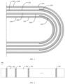
- FIG. 1 a schematic diagram of a curved surface area group of a battery cell in an embodiment of the present application is shown. At least one curved surface area group composed of the negative electrode curved surface area and the positive electrode curved surface area positioned outside and adjacent to the negative electrode curved surface area is included at a corner of the battery cell. Specifically, 2 curved surface area groups are shown in FIG. 1 .
- the negative electrode plate comprises a negative electrode current collector 100, a base negative electrode active layer 101, and a modified negative electrode active layer 102; and the base negative electrode active layer 101 is positioned at least on a surface of an outside of the negative electrode current collector 100, and the modified negative electrode active layer 102 is positioned on a surface of the base negative electrode active layer 101 on an outside of the negative electrode curved surface area.
- the positive electrode plate comprises a positive electrode current collector 200 and a positive electrode active layer 201 positioned on a surface of an inside of the positive electrode current collector 200.
- the material of the base negative electrode active layer 101 and the material of the modified negative electrode active layer 102 are the same or different.
- the material of the modified negative electrode active layer 102 comprises at least one of a carbon material and a silicon-based material.
- the carbon material comprises one or more of ordinary graphite, fast-charge graphite, and artificial graphite.
- the silicon-based material comprises one or more of elemental silicon, a silicon oxide compound, a silicon carbon composite, a silicon nitrogen composite, and a silicon alloy.
- the silicon-based material comprises one or more of a silicon oxide compound and a silicon carbon composite.
- the battery cell is of a wound structure, and the direction from inside to outside of the battery cell indicates the direction from an inside of the battery cell to an outside of the battery cell in the thickness direction of the electrode plate.
- the outside of the negative electrode current collector 100 indicates a side of the negative electrode current collector 100 facing the positive electrode curved surface area in the curved surface area group where the negative electrode current collector 100 is positioned
- the inside of the positive electrode current collector 200 indicates a side of the positive electrode current collector 200 facing the negative electrode curved surface area in the curved surface area group where the positive electrode current collector 200 is positioned.
- the surface density of the modified negative electrode active layer is smaller than that of the base negative electrode active layer outside the negative electrode curved surface area.
- the surface density of the modified negative electrode active layer in the adjacent curved surface area groups is reduced at a level of 1.6 mg/1540.25 mm 2 -45 mg/1540.25 mm 2 .
- the surface density of the modified negative electrode active layer in the adjacent curved surface area groups can be, but not limited to at a level of 1.6 mg/1540.25 mm 2 , 2 mg/1540.25 mm 2 , 5 mg/1540.25 mm 2 , 10 mg/1540.25 mm 2 , 15 mg/1540.25 mm 2 , 17.6 mg/1540.25 mm 2 , 20 mg/1540.25 mm 2 , 25 mg/1540.25 mm 2 , 30 mg/1540.25 mm 2 , 35 mg/1540.25 mm 2 , 40 mg/1540.25 mm 2 , 45 mg/1540.25 mm 2 , etc. It can be understood that the surface density of the modified negative electrode active layer in the adjacent curved surface area groups
- the surface density of the modified negative electrode active layer in the nth curved surface area group can be calculated by the surface density of the base negative electrode active layer of an outside of the negative electrode curved surface area, the arc length of the negative electrode current collector in the negative electrode curved surface area in the nth curved surface area group, and the arc length of the positive electrode current collector in the positive electrode curved surface area in the nth curved surface area group, so as to design the surface density of the modified negative electrode active layer in the nth curved surface area group, the lithium intercalation of the negative electrode can be matched with the lithium de-intercalation of the positive electrode at the corner of the battery cell, and the problem of lithium precipitation in a negative electrode is avoided.
- L an and L cn satisfy formula (II) and formula (III) respectively:
- L an ⁇ ⁇ b n + 2 a n 2 2 ⁇ b n 2 4 ⁇ b n and
- L cn ⁇ ⁇ b n + ⁇ n + 2 a n + ⁇ n 2 2 ⁇ b n + ⁇ n 2 4 ⁇ b n
- a n represents a length of a short axis of the negative electrode current collector of the negative electrode curved surface area in the nth curved surface area group
- b n represents a length of a long axis of the negative electrode current collector of the negative electrode curved surface area in the nth curved surface area group
- ⁇ n represents a difference between a curvature radius of the positive electrode current collector of the positive electrode curved surface area and a curvature radius of the negative electrode current collector of the negative electrode curved surface area in the nth curved surface area group
- ⁇ represents the ratio of circumference to diameter.
- a plurality of the curved surface area groups are included, and the surface density of the modified negative electrode active layers in each surface area group are equal.
- L a0 and L c0 satisfy formula (V) and formula (VI) respectively:
- L a 0 ⁇ ⁇ b 0 + 2 a 0 2 2 ⁇ b 0 2 4 ⁇ b 0
- L c 0 ⁇ ⁇ b 0 + ⁇ 0 + 2 a 0 + ⁇ 0 2 2 ⁇ b 0 + ⁇ 0 2 4 ⁇ b 0
- a 0 represents a length of a short axis of the negative electrode current collector of the negative electrode curved surface area in the innermost layer curved surface area group
- b 0 represents a length of a long axis of the negative electrode current collector of the negative electrode curved surface area in the innermost layer curved surface area group
- ⁇ 0 represents a difference between the curvature radius of the positive electrode current collector of the positive electrode curved surface area and the curvature radius of the negative electrode current collector of the negative electrode curved surface area in the innermost layer curved surface area group
- the surface densities of the modified negative electrode active layers in each curved surface area group are equal, the surface density of the modified negative electrode active layer in the innermost layer curved surface area group is taken as a reference, the surface densities of the modified layers in the each curved surface area group are equal and is the surface density of the modified negative electrode active layer in the innermost layer curved surface area group.
- the surface density of the modified negative electrode active layer in each curved surface area group may also not be equal to the surface densities of the modified negative electrode active layer in one certain curved surface area group in each curved surface area group calculated by formula (V) and formula (VI).
- 1 of the curved surface area group is included, and the surface density of the modified negative electrode active layer in the curved surface area group satisfies formula (IV), wherein CW 0 represents the surface density of the modified negative electrode active layer in the curved surface area group.
- L a0 and L c0 in formula (IV) respectively satisfy formula (V) and formula (VI), wherein a 0 represents a length of a short axis of the negative electrode current collector of the negative electrode curved surface area in the curved surface area group, b 0 represents a length of a long axis of the negative electrode current collector of the negative electrode curved surface area in the curved surface area group, ⁇ 0 represents a difference between the curvature radius of the positive electrode current collector of the positive electrode curved surface area and the curvature radius of the negative electrode current collector of the negative electrode curved surface area in the curved surface area group, and ⁇ represents the ratio of circumference to diameter.
- a ratio of the thickness of the base negative electrode active layer to that of the modified negative electrode active layer is (1-22) : 1.
- the ratio of the thickness of the base negative electrode active layer to that of the modified negative electrode active layer is 1 : 1, 5 : 1, 10 : 1, 15 : 1, 20 : 1, etc.
- the thickness of the base negative electrode active layer is 65 ⁇ m-180 ⁇ m.
- the thickness of the base negative electrode active layer is 65 ⁇ m, 70 ⁇ m, 75 ⁇ m, 80 ⁇ m, 90 ⁇ m, 100 ⁇ m, 120 ⁇ m, 150 ⁇ m, 170 ⁇ m, etc.
- the thickness of the modified negative electrode active layer is 12 ⁇ m-32 ⁇ m.
- the thickness of the modified negative electrode active layer is 12 ⁇ m, 15 ⁇ m, 18 ⁇ m, 20 ⁇ m, 22 ⁇ m, 25 ⁇ m, 28 ⁇ m, 30 ⁇ m, 32 ⁇ m, etc.
- the surface density of the base negative electrode active layer is 90 mg/1540.25 mm 2 -250 mg/1540.25 mm 2 .
- the surface density of the base negative electrode active layer is 90 mg/1540.25 mm 2 , 100 mg/1540.25 mm 2 , 120 mg/1540.25 mm 2 , 150 mg/1540.25 mm 2 , 180 mg/1540.25 mm 2 , 200 mg/1540.25 mm 2 , etc.
- the surface density of the modified negative electrode active layer is 16.2 mg/1540.25 mm 2 -45 mg/1540.25 mm 2 .
- the surface density of the modified negative electrode active layer is 16.2 mg/1540.25 mm 2 , 20 mg/1540.25 mm 2 , 25 mg/1540.25 mm 2 , 30 mg/1540.25 mm 2 , 35 mg/1540.25 mm 2 , 40 mg/1540.25 mm 2 , 45 mg/1540.25 mm 2 , etc.
- the positive electrode plate comprises a positive electrode current collector and a positive electrode active layer positioned on a surface of an inside of the positive electrode current collector.
- the thickness of the positive electrode active layer is 65 ⁇ m-160 ⁇ m.
- the thickness of the positive electrode active layer is 65 ⁇ m, 70 ⁇ m, 75 ⁇ m, 80 ⁇ m, 90 ⁇ m, 100 ⁇ m, 110 ⁇ m, 120 ⁇ m, 130 ⁇ m, 140 ⁇ m, 150 ⁇ m, 160 ⁇ m, etc.
- the surface density of the positive electrode active layer is 150 ⁇ m-400 ⁇ m.
- the surface density of the positive electrode active layer is 150 ⁇ m, 180 ⁇ m, 200 ⁇ m, 250 ⁇ m, 300 ⁇ m, 350 ⁇ m, 400 ⁇ m, etc.
- the present application further provides a method for preparing the battery cell, characterized by comprising the steps of:
- adjusting the ratio in surface capacity of two opposite surfaces of the preset negative electrode curved surface area and the preset positive electrode curved surface area in the preset curved surface area group comprises the steps of: forming a base negative electrode active layer on an outside surface of at least a preset negative electrode current collector; and forming a modified negative electrode active layer on a surface of the base negative electrode active layer of the preset negative electrode curved surface area.
- outside surface of the preset negative electrode current collector indicates a surface of the negative electrode current collector facing outward after the winding.
- the base negative electrode active layer may be formed by coating a basic active slurry and a modified active slurry may be formed by coating the modified active slurry.
- the basic active slurry and the modified active slurry are the same or different.
- a secondary battery comprises a positive electrode plate, a negative electrode plate, an electrolyte and a separator.
- active ions are intercalated and deintercalated back and forth between the positive electrode plate and the negative electrode plate.
- the electrolyte functions to conduct ions between the positive electrode plate and the negative electrode plate.
- the separator is arranged between the positive electrode plate and the negative electrode plate and mainly functions to prevent the positive and negative electrodes from short-circuiting while enabling ions to pass through.
- the positive electrode plate includes a positive electrode current collector and a positive electrode film layer provided on at least one surface of the positive electrode current collector, the positive electrode film layer including a positive electrode active material.
- the positive electrode current collector has two surfaces opposite in its own thickness direction, and the positive electrode active material layer is provided on either or both of the two opposite surfaces of the positive electrode current collector.
- the positive electrode current collector may be a metal foil or a composite current collector.
- a metal foil an aluminum foil can be used.
- the composite current collector may comprise a polymer material base layer and a metal layer formed on at least one surface of the polymer material base layer.
- the composite current collector can be formed by forming a metal material (aluminum, an aluminum alloy, nickel, a nickel alloy, titanium, a titanium alloy, silver and a silver alloy, etc.) on a polymer material substrate (such as polypropylene (PP), polyethylene terephthalate (PET), polybutylene terephthalate (PBT), polystyrene (PS), polyethylene (PE), etc.).
- PP polypropylene
- PET polyethylene terephthalate
- PBT polybutylene terephthalate
- PS polystyrene
- PE polyethylene
- the positive electrode active material can be a positive electrode active material for batteries well-known in the art.
- the positive electrode active material may comprise at least one of the following materials: lithium-containing phosphates of an olivine structure, lithium transition metal oxides, and their respective modified compounds.
- the present application is not limited to these materials, and other conventional materials that can be used as positive electrode active materials for batteries may also be used. These positive electrode active materials may be used alone or in combination of two or more.
- examples of lithium transition metal oxides may include, but are not limited to, at least one of lithium cobalt oxide (e.g., LiCoO 2 ), lithium nickel oxide (e.g., LiNiO 2 ), lithium manganese oxide (e.g., LiMnO 2 , LiMn 2 O 4 ), lithium nickel cobalt oxide, lithium manganese cobalt oxide, lithium nickel manganese oxide, lithium nickel cobalt manganese oxide (e.g., LiNi 1/3 Co 1/3 Mn 1/3 O 2 (also referred to as NCM 333 ), LiNi 0.5 Co 0.2 Mn 0.3 O 2 (also referred to as NCM 523 ), LiNi 0.5 Co 0.25 Mn 0.25 O 2 (also referred to as NCM 211 ), LiNi 0.6 Co 0.2 Mn 0.2 O 2 (also referred to as NCM 622 ), LiNi 0.8 Co 0.1 Mn 0.1 O 2 (also referred to as NCM 811 )), lithium nickel cobalt aluminum oxide
- lithium -containing phosphates of olivine structure may include, but are not limited to, at least one of lithium iron phosphate (e.g., LiFePO 4 (also referred to as LFP)), lithium iron phosphate and carbon composites, lithium manganese phosphate (e.g., LiMnPO 4 ), lithium manganese phosphate and carbon composites, lithium iron manganese phosphate, and lithium iron manganese phosphate and carbon composites.
- the weight ratio of the positive electrode active material in the positive electrode film layer is 80-100 wt%, based on the total weight of the positive electrode film layer.
- the positive electrode film layer may further optionally comprise a binder.
- the binder may include at least one of polyvinylidene fluoride (PVDF), polytetrafluoroethylene (PTFE), vinylidene fluoride-tetrafluoroethylene-propylene terpolymer, vinylidene fluoridehexafluoropropylene-tetrafluoroethylene terpolymer, tetrafluoroethylene-hexafluoropropylene copolymer, and fluorine-containing acrylate resin.
- PVDF polyvinylidene fluoride
- PTFE polytetrafluoroethylene
- PTFE polytetrafluoroethylene
- vinylidene fluoride-tetrafluoroethylene-propylene terpolymer vinylidene fluoridehexafluoropropylene-tetrafluoroethylene terpolymer
- the positive electrode film layer also optionally comprises a conductive agent.
- the conductive agent may include at least one of superconducting carbon, acetylene black, carbon black, Ketjen black, carbon dots, carbon nanotubes, graphene, and carbon nanofibers.
- the weight ratio of the conductive agent in the positive electrode film layer is 0-20 wt%, based on the total weight of the positive electrode film layer.
- the positive electrode plate can be prepared by the above-mentioned components for preparing the positive electrode plate, such as the positive electrode active material, the conductive agent, the binder and any other components, are dispersed in a solvent (e.g., N-methylpyrrolidone) to form a positive electrode slurry, wherein the positive electrode slurry has a solid content of 40-80 wt%, and the viscosity at room temperature thereof is adjusted to 5,000-25,000 mPa ⁇ s; and the positive electrode slurry is coated onto the surface of the positive electrode current collector, dried and then cold pressed by means of a cold-rolling mill to form a positive electrode plate, wherein the unit surface density of the positive electrode powder coating is 150-350 mg/m 2 , and the positive electrode plate has the compacted density of 3.0-3.6 g/cm 3 , optionally 3.3-3.5 g/cm 3 .
- the positive electrode plate may be prepared by using the positive electrode plate as a main body of the positive electrode plate, and forming a solid electrolyte interface film on a surface of the main body of the positive electrode plate.
- the negative electrode plate comprises a negative electrode current collector and a negative electrode film layer provided on at least one surface of the negative electrode current collector, the negative electrode film layer comprising a negative electrode active material.
- the negative electrode current collector has two surfaces opposite in its own thickness direction, and the negative electrode film layer is provided on either or both of the two opposite surfaces of the negative electrode current collector.
- the negative electrode current collector may be a metal foil or a composite current collector.
- a metal foil a copper foil can be used.
- the composite current collector may comprise a polymer material base layer and a metal layer formed on at least one surface of the polymer material substrate.
- the composite current collector can be formed by forming a metal material (copper, a copper alloy, nickel, a nickel alloy, titanium, a titanium alloy, silver and a silver alloy, etc.) on a polymer material substrate (e.g., polypropylene (PP), polyethylene terephthalate (PET), polybutylene terephthalate (PBT), polystyrene (PS), polyethylene (PE), etc.).
- PP polypropylene
- PET polyethylene terephthalate
- PBT polybutylene terephthalate
- PS polystyrene
- PE polyethylene
- the negative electrode active material can be a negative electrode active material known in the art for batteries.
- the negative electrode active material may comprise at least one of the following materials: artificial graphite, natural graphite, soft carbon, hard carbon, a silicon-based material, a tin-based material and lithium titanate, etc.
- the silicon-based material may be selected from at least one of elemental silicon, a silicon oxide compound, a silicon carbon composite, a silicon nitrogen composite, and a silicon alloy.
- the tin-based material may be selected from at least one of elemental tin, a tin oxide compound, and a tin alloy.
- the present application is not limited to these materials, and other conventional materials that can be used as negative electrode active materials for batteries can also be used.
- These negative electrode active materials may be used alone or as a combination of two or more.
- the weight ratio of the negative electrode active material in the negative electrode film layer is 70-100 wt%, based on the total weight of the negative electrode film layer.
- the negative electrode film layer may optionally comprise a binder.
- the binder may be selected from at least one of a butadiene styrene rubber (SBR), polyacrylic acid (PAA), sodium polyacrylate (PAAS), polyacrylamide (PAM), polyvinyl alcohol (PVA), sodium alginate (SA), polymethacrylic acid (PMAA) and carboxymethyl chitosan (CMCS).
- SBR butadiene styrene rubber
- PAA polyacrylic acid
- PAAS sodium polyacrylate
- PAM polyacrylamide
- PVA polyvinyl alcohol
- SA sodium alginate
- PMAA polymethacrylic acid
- CMCS carboxymethyl chitosan
- the negative electrode film layer may optionally comprise a conductive agent.
- the conductive agent may be selected from at least one of superconductive carbon, acetylene black, carbon black, Ketjen black, carbon dots, carbon nanotubes, graphene, and carbon nanofibers.
- the weight ratio of the conductive agent in the negative electrode film layer is 0-20 wt%, based on the total weight of the negative electrode film layer.
- the negative electrode film layer may optionally comprise other auxiliary agents, such as thickener (e.g., sodium carboxymethyl cellulose (CMC-Na)), etc.
- auxiliary agents such as thickener (e.g., sodium carboxymethyl cellulose (CMC-Na)), etc.
- the weight ratio of the other auxiliary agents in the negative electrode film layer is 0-15 wt%, based on the total weight of the negative electrode film layer.
- the negative electrode plate can be prepared by the above-mentioned components for preparing the negative electrode plate, such as the negative electrode active material, the conductive agent, the binder and any other components, are dispersed in a solvent (e.g., deionized water) to form a negative electrode slurry, wherein the negative electrode slurry has a solid content of 30-70 wt%, and the viscosity at room temperature thereof is adjusted to 2,000-10,000 mPa•s; and the resulting negative electrode slurry is coated onto a negative electrode current collector, followed by a drying procedure and cold pressing (e.g., double rollers), so as to obtain the negative electrode plate.
- the unit surface density of the negative electrode powder coating is 75-220 mg/m 2
- the negative electrode plate has the compacted density of 1.2-2.0 g/cm 3 .
- the negative electrode plate may be prepared by using the negative electrode plate as a main body of the negative electrode plate, and forming a solid electrolyte interface film on a surface of the main body of the negative electrode plate.
- the electrolyte functions to conduct ions between the positive electrode plate and the negative electrode plate.
- the type of the electrolyte is not specifically limited in the present application and can be selected as necessary.
- the electrolyte may be in a liquid state, a gel state or an all-solid state.
- an electrolyte solution is used as the electrolyte.
- the electrolyte solution comprises an electrolyte salt and a solvent.
- the electrolyte salt may be selected from one or more of lithium hexafluorophosphate (LiPF 6 ), lithium tetrafluoroborate (LiBF 4 ), lithium perchlorate (LiClO 4 ), lithium hexafluoroarsenate (LiAsF 6 ), lithium bisfluorosulfonimide (LiFSI), lithium bistrifluoromethanesulfonimide (LiTFSI), lithium trifluoromethanesulfonate (LiTFS), lithium difluorooxalate borate (LiDFOB), lithium dioxalate borate (LiBOB), lithium difluorophosphate (LiPO 2 F 2 ), lithium bisoxalatodifluorophosphate (LiDFOP) and lithium tetrafluorooxalate phosphate (LiTFOP).
- the concentration of the electrolyte salt is typically 0.5-5 mol/L.
- the solvent may be selected from one or more of fluoroethylene carbonate (FEC), ethylene carbonate (EC), propylene carbonate (PC), ethyl methyl carbonate (EMC), diethyl carbonate (DEC), dimethyl carbonate (DMC), dipropyl carbonate (DPC), methyl propyl carbonate (MPC), ethyl propyl carbonate (EPC), butylene carbonate (BC), methyl formate (MF), methyl acetate (MA), ethyl acetate (EA), propyl acetate (PA), methyl propionate (MP), ethyl propionate (EP), propyl propionate (PP), methyl butyrate (MB), ethyl butyrate (EB), 1,4-butyrolactone (GBL), sulfolane (SF), dimethyl sulfone (MSM), methyl ethyl sulfone (EMS) and diethyl sulfone (FEC),
- the electrolyte solution may optionally include an additive.
- the additive may include a negative electrode film-forming additive and a positive electrode film-forming additive, and may further include an additive that can improve certain performances of the battery, such as an additive that improves the overcharge performance of the battery, or an additive that improves the high temperature or low-temperature performance of the battery.
- the secondary battery further comprises a separator.
- the type of the separator is not particularly limited in the present application, and any well-known porous-structure separator with good chemical stability and mechanical stability may be selected.
- the material of the separator may be selected from at least one of glass fibers, nonwoven fabrics, polyethylene, polypropylene and polyvinylidene fluoride.
- the separator may be either a singlelayer film or a multi-layer composite film, and is not limited particularly. When the separator is a multi-layer composite film, the materials in the respective layers may be same or different, which is not limited particularly.
- an electrode assembly may be formed by a positive electrode plate, a negative electrode plate and a separator by a winding process or a stacking process.
- the secondary battery may comprise an outer package.
- the outer package may be used to encapsulate the above-mentioned electrode assembly and electrolyte.
- the outer package of the secondary battery can be a hard housing, for example, a hard plastic housing, an aluminum housing, a steel housing, etc.
- the outer package of the secondary battery may also be a soft bag, such as a pouch-type soft bag.
- the material of the soft bag may be plastics, and the examples of plastics may comprise polypropylene, polybutylene terephthalate, polybutylene succinate, etc.
- the shape of the secondary battery is not particularly limited in the present application and may be cylindrical, square or of any other shape.
- Fig. 3 shows a secondary battery 5 with a square structure as an example.
- the outer package may comprise a housing 51 and a cover plate 53.
- the housing 51 may comprise a bottom plate and side plates connected to the bottom plate, and the bottom plate and the side plates enclose to form an accommodating cavity.
- the housing 51 has an opening in communication with the accommodating cavity, and the cover plate 53 may cover the opening to close the accommodating cavity.
- the positive electrode plate, the negative electrode plate, and the separator may be subjected to a winding process or a laminating process to form an electrode assembly 52.
- the electrode assembly 52 is encapsulated in the accommodating cavity.
- the electrolyte solution infiltrates the electrode assembly 52.
- the number of the electrode assemblies 52 contained in the secondary battery 5 may be one or more, and can be selected by those skilled in the art according to actual requirements.
- the secondary battery can be assembled into a battery module, and the number of the secondary batteries contained in the battery module may be one or more, and the specific number can be selected by those skilled in the art according to the application and capacity of the battery module.
- FIG. 5 shows a battery module 4 as an example.
- a plurality of secondary batteries 5 may be sequentially arranged in the length direction of the battery module 4.
- the secondary batteries may also be arranged in any other manner.
- the plurality of secondary batteries 5 may be fixed by fasteners.
- the battery module 4 may further comprise an outer housing with an accommodating space, and the plurality of secondary batteries 5 are accommodated in the accommodating space.
- the above battery module may also be assembled into a battery pack, the number of the battery modules contained in the battery pack may be one or more, and the specific number can be selected by those skilled in the art according to the application and capacity of the battery pack.
- the battery pack 1 may comprise a battery box and a plurality of battery modules 4 provided in the battery box.
- the battery box comprises an upper box body 2 and a lower box body 3, wherein the upper box body 2 may cover the lower box body 3 to form a closed space for accommodating the battery modules 4.
- the plurality of the battery modules 4 may be arranged in the battery box in any manner.
- the present application further provides a power consuming device.
- the power consuming device comprises at least one of the secondary battery, the battery module, or the battery pack provided by the present application.
- the secondary battery, battery module or battery pack can be used as a power source of the power consuming device or as an energy storage unit of the power consuming device.
- the power consuming device may include a mobile device (e.g., a mobile phone, a laptop computer, etc.), an electric vehicle (e.g., a pure electric vehicle, a hybrid electric vehicle, a plug-in hybrid electric vehicle, an electric bicycle, an electric scooter, an electric golf cart, an electric truck, etc.), an electric train, ship, and satellite, an energy storage system, etc., but is not limited thereto.
- the secondary battery, battery module or battery pack can be selected according to the usage requirements thereof.
- Fig. 8 shows a power consuming device as an example.
- the power consuming device may be a pure electric vehicle, a hybrid electric vehicle, a plug-in hybrid electric vehicle, etc.
- a battery pack or a battery module may be used.
- the device may be a mobile phone, a tablet computer, a laptop computer, etc.
- the device is generally required to be thin and light, and may have a secondary battery used as a power source.
- a positive electrode active material of ternary material nickel cobalt manganese (NCM), a conductive agent of acetylene black, and a binder of polyvinylidene fluoride (PVDF) were added into a certain amount of NMP at a mass ratio of 97 : 2 : 1, the materials were uniformly stirred to prepare a positive electrode slurry; and the positive electrode slurry was uniformly coated onto an aluminum foil with a thickness of 15 ⁇ m to a surface density of 260 mg/1540.25 cm 2 , followed by drying, cold-pressing, die-cutting, and slitting to prepare a positive electrode plate.
- NCM nickel cobalt manganese
- PVDF polyvinylidene fluoride
- a negative electrode active material of graphite, a conductive agent of Super P, a thickener (CMC), and a binder (SBR) were added into a certain amount of water at a mass ratio of 95 : 3 : 1 : 1, and the materials were uniformly stirred to prepare a basic active slurry; and the basic active slurry was uniformly coated onto a copper foil with a thickness of 6 ⁇ m to a surface density of 162 mg/1540.25 cm 2 , and the plate was dried by an oven to obtain a negative electrode plate preform with a base negative electrode active layer.
- a modified active slurry was coated on a surface of the base negative electrode active layer of a preset negative electrode curved surface area of the negative electrode plate preform obtained in step (1).
- the modified active slurry is prepared by adding natural graphite, a conductive agent of Super P, a thickener (CMC), and a binder (SBR) at a mass ratio of 95 : 3 : 1 : 1 into water for stirring.
- the plate was dried by an oven, cold-pressed after the drying, and then die-cut and slit to obtain a negative electrode plate with the base negative electrode active layer and the modified negative electrode active layer.
- the surface density of the modified negative electrode active layer in each curved surface area group is 29.2 mg/1540.25 cm 2 , 26.3 mg/1540.25 cm 2 , 22.4 mg/1540.25 cm 2 , 17.6 mg/1540.25 cm 2 , 11.8 mg/1540.25 cm 2 , and 5.4 mg/1540.25 cm 2 in sequence.
- Polyethylene is used as a base film, and aluminum oxide with a thickness of 3 ⁇ m is coated onto the base film to obtain a separator.
- Lithium hexafluorophosphate was dissolved in a solvent with a volume ratio of DMC : DEC : EC at 1 : 1 : 1 to obtain an electrolyte solution for lithium-ion batteries.
- Fig. 9 is a topography of a disassembled negative electrode plate of a battery cell after formation in the present example.
- the difference of the present example was that when the modified negative electrode active layer was prepared in the preparation of negative electrode plate in step (2), the modified slurry was the same as the basic active slurry.
- the difference of the present example was that when the modified negative electrode active layer was prepared in the preparation of negative electrode plate in step (2), the modified slurry was prepared by adding artificial graphite, a silicon oxide material (at least including SiO x , wherein 0 ⁇ x ⁇ 2), conductive carbon of Super P, a thickener (CMC), and a binder (SBR) at a mass ratio of 92 : 3 : 3 : 1 : 1 into water for stirring.
- a silicon oxide material at least including SiO x , wherein 0 ⁇ x ⁇ 2
- CMC thickener
- SBR binder
- Fig. 10 is a topography of a disassembled negative electrode plate of a battery cell after formation in the present example.
- Fig. 11 is a topography of a disassembled negative electrode plate of a battery cell after formation in the comparative example.
- the difference of the present comparative example was that along the direction from inside to outside of the battery cell, the surface density of the modified negative electrode active layer in each curved surface area group was 5.4 mg/1540.25 cm 2 , 11.8 mg/1540.25 cm 2 , 17.6 mg/1540.25 cm 2 , 22.4 mg/1540.25 cm 2 , 26.3 mg/1540.25 cm 2 , and 29.2 mg/1540.25 cm 2 in sequence.
- the difference of the present comparative example was that when the modified negative electrode active layer was prepared in the preparation of negative electrode plate in step (2), the surface densities of the modified negative electrode active layers in each curved surface area group were equal and 11.8 mg/1540.25 cm 2 .
- the difference of the present comparative example was that when the modified negative electrode active layer was prepared in the preparation of negative electrode plate in step (2), the modified negative active layer was prepared only in the innermost layer curved surface area group, and the surface density was 29.2 mg/1540.25 cm 2 .
- Table 1 No. Lithium precipitation degree Capacity retention rate after 10 cycles
- Example 1 No lithium precipitation 99.9%
- Example 2 No lithium precipitation 99.9%
- Example 3 No lithium precipitation 99.9%
- Comparative example 1 Severe lithium precipitation 99.1% Comparative example 2 Moderate lithium precipitation 99.4% Comparative example 3 Slight lithium precipitation 99.6% Comparative example 4 Moderate lithium precipitation 99.3%
- the lithium precipitation degree is evaluated by observing the disassembled negative electrode plate. The results are shown in Table 1. After fully charged, the battery was disassembled and observed in the environment with an air humidity lower than 2%, and the lithium precipitation degree is determined by the color depth of the lithium precipitation: Slight lithium precipitation: light grey Moderate lithium precipitation: grey white Severe lithium precipitation: bright white Meanwhile, when no lithium was precipitated, a ratio in surface capacity of the two opposite surfaces of the negative electrode curved surface area and the positive electrode curved surface area is ⁇ 1.
Landscapes
- Chemical & Material Sciences (AREA)
- Engineering & Computer Science (AREA)
- Chemical Kinetics & Catalysis (AREA)
- Electrochemistry (AREA)
- General Chemical & Material Sciences (AREA)
- Manufacturing & Machinery (AREA)
- Materials Engineering (AREA)
- Composite Materials (AREA)
- Battery Electrode And Active Subsutance (AREA)
Applications Claiming Priority (1)
| Application Number | Priority Date | Filing Date | Title |
|---|---|---|---|
| PCT/CN2022/130207 WO2024098171A1 (zh) | 2022-11-07 | 2022-11-07 | 电芯及其制备方法、二次电池和用电装置 |
Publications (2)
| Publication Number | Publication Date |
|---|---|
| EP4564447A1 true EP4564447A1 (de) | 2025-06-04 |
| EP4564447A4 EP4564447A4 (de) | 2026-01-14 |
Family
ID=91031598
Family Applications (1)
| Application Number | Title | Priority Date | Filing Date |
|---|---|---|---|
| EP22964650.0A Pending EP4564447A4 (de) | 2022-11-07 | 2022-11-07 | Batteriezelle und herstellungsverfahren dafür, sekundärbatterie und elektrische vorrichtung |
Country Status (4)
| Country | Link |
|---|---|
| US (1) | US20250105366A1 (de) |
| EP (1) | EP4564447A4 (de) |
| CN (1) | CN118843948A (de) |
| WO (1) | WO2024098171A1 (de) |
Family Cites Families (8)
| Publication number | Priority date | Publication date | Assignee | Title |
|---|---|---|---|---|
| KR100274884B1 (ko) * | 1998-01-22 | 2000-12-15 | 김순택 | 양.음극의 용량비를 보상한 2차 전지 |
| JP5622048B2 (ja) * | 2011-02-23 | 2014-11-12 | 株式会社デンソー | 捲回型電池の製造方法および製造装置 |
| CN105958124B (zh) * | 2016-07-21 | 2018-07-24 | 东莞新能源科技有限公司 | 一种锂离子电池及其制备方法 |
| EP4068452B1 (de) * | 2021-02-04 | 2025-12-17 | Contemporary Amperex Technology (Hong Kong) Limited | Elektrodenanordnung und herstellungsverfahren und -system dafür sowie batteriezelle und batterie |
| CN120545499A (zh) * | 2021-04-22 | 2025-08-26 | 宁德时代新能源科技股份有限公司 | 电极组件、电池单体、电池以及用电装置 |
| CN113381080B (zh) * | 2021-06-15 | 2022-06-10 | 广东国光电子有限公司 | 一种电池卷芯的制作方法及电池卷芯 |
| CN114744147B (zh) * | 2022-06-13 | 2022-10-11 | 宁德时代新能源科技股份有限公司 | 正极极片、电极组件、电池单体、电池及用电设备 |
| CN115084428A (zh) * | 2022-06-30 | 2022-09-20 | 东莞锂威能源科技有限公司 | 一种改善卷芯拐角析锂的方法、电池的制备工艺及电池 |
-
2022
- 2022-11-07 CN CN202280093531.2A patent/CN118843948A/zh active Pending
- 2022-11-07 EP EP22964650.0A patent/EP4564447A4/de active Pending
- 2022-11-07 WO PCT/CN2022/130207 patent/WO2024098171A1/zh not_active Ceased
-
2024
- 2024-12-10 US US18/974,807 patent/US20250105366A1/en active Pending
Also Published As
| Publication number | Publication date |
|---|---|
| EP4564447A4 (de) | 2026-01-14 |
| US20250105366A1 (en) | 2025-03-27 |
| WO2024098171A1 (zh) | 2024-05-16 |
| CN118843948A (zh) | 2024-10-25 |
Similar Documents
| Publication | Publication Date | Title |
|---|---|---|
| US12308459B2 (en) | Battery module, battery pack, power consumption apparatus, and manufacturing method and manufacturing device of battery module | |
| EP4358215A1 (de) | Elektrodenpolstück und herstellungsverfahren dafür, sekundärbatterie, batteriemodul und batteriepack | |
| US20230216028A1 (en) | Negative electrode plate, secondary battery, battery module, battery pack, and electrical device | |
| EP4362156A1 (de) | Lithium-ionen-batterie, batteriemodul, batteriepack und elektrische vorrichtung | |
| US20230124276A1 (en) | Lithium-Ion Battery | |
| US20230336014A1 (en) | Method for supplementing lithium for secondary battery and method for charging and discharging secondary battery | |
| EP4235832A1 (de) | Positivelektrodenverbundmaterial für lithium-ionen-sekundärbatterie, positivelektrode und batterie | |
| EP4310983A1 (de) | Batteriepack und elektrische vorrichtung | |
| US11791460B2 (en) | Electrode assembly, secondary battery, battery module, battery pack and power consuming device | |
| EP4287331A1 (de) | Sekundärbatterie, batteriemodul, batteriepack und elektrische vorrichtung | |
| EP4362137A1 (de) | Kohlenstoffmaterial und herstellungsverfahren dafür und verwendung davon, negativelektrodenfolie, sekundärbatterie und elektrische vorrichtung | |
| CN118398870A (zh) | 电池单体、电池以及用电装置 | |
| US12418047B2 (en) | Electrolyte, secondary battery, battery module, battery pack, and power consuming device | |
| US20230146812A1 (en) | Negative electrode plate, secondary battery, battery module, battery pack, and electric apparatus | |
| US20230387380A1 (en) | Secondary battery | |
| EP4258383A1 (de) | Positivelektrodenfolie, sekundärbatterie, batteriemodul, batteriepack, elektrische vorrichtung und verfahren zum ausgleichen der internen spannungsdifferenz einer batterie | |
| EP4235902A1 (de) | Negativelektrodenfolie und herstellungsverfahren dafür, sekundärbatterie, batteriemodul, batteriepack und stromverbrauchende vorrichtung | |
| US20240186479A1 (en) | Negative electrode plate, secondary battery, battery module, battery pack, and electric apparatus | |
| US11799161B2 (en) | Battery pack and power consuming device | |
| EP4564447A1 (de) | Batteriezelle und herstellungsverfahren dafür, sekundärbatterie und elektrische vorrichtung | |
| US20240258602A1 (en) | Battery pack and power consuming device | |
| EP4664541A1 (de) | Batterie, herstellungsverfahren und elektrische vorrichtung | |
| US20250336983A1 (en) | Current collector and preparation method therefor, secondary battery, and electric device | |
| EP4510265A1 (de) | Elektrolytlösung, sekundärbatterie, batteriemodul, batteriepack und elektrische vorrichtung | |
| US20260088281A1 (en) | Positive electrode active material, positive electrode plate, battery cell, battery and electrical apparatus |
Legal Events
| Date | Code | Title | Description |
|---|---|---|---|
| STAA | Information on the status of an ep patent application or granted ep patent |
Free format text: STATUS: THE INTERNATIONAL PUBLICATION HAS BEEN MADE |
|
| PUAI | Public reference made under article 153(3) epc to a published international application that has entered the european phase |
Free format text: ORIGINAL CODE: 0009012 |
|
| STAA | Information on the status of an ep patent application or granted ep patent |
Free format text: STATUS: REQUEST FOR EXAMINATION WAS MADE |
|
| 17P | Request for examination filed |
Effective date: 20250225 |
|
| AK | Designated contracting states |
Kind code of ref document: A1 Designated state(s): AL AT BE BG CH CY CZ DE DK EE ES FI FR GB GR HR HU IE IS IT LI LT LU LV MC ME MK MT NL NO PL PT RO RS SE SI SK SM TR |
|
| A4 | Supplementary search report drawn up and despatched |
Effective date: 20251211 |
|
| RIC1 | Information provided on ipc code assigned before grant |
Ipc: H01M 4/13 20100101AFI20251205BHEP Ipc: H01M 10/0587 20100101ALI20251205BHEP Ipc: H01M 10/04 20060101ALI20251205BHEP Ipc: H01M 10/0525 20100101ALI20251205BHEP Ipc: H01M 4/02 20060101ALI20251205BHEP |
|
| DAV | Request for validation of the european patent (deleted) | ||
| DAX | Request for extension of the european patent (deleted) |