EP4187650A1 - Lithium ion secondary battery, battery core, negative electrode plate, and apparatus - Google Patents
Lithium ion secondary battery, battery core, negative electrode plate, and apparatus Download PDFInfo
- Publication number
- EP4187650A1 EP4187650A1 EP23151861.4A EP23151861A EP4187650A1 EP 4187650 A1 EP4187650 A1 EP 4187650A1 EP 23151861 A EP23151861 A EP 23151861A EP 4187650 A1 EP4187650 A1 EP 4187650A1
- Authority
- EP
- European Patent Office
- Prior art keywords
- current collector
- layer
- lithium ion
- ion secondary
- negative
- Prior art date
- Legal status (The legal status is an assumption and is not a legal conclusion. Google has not performed a legal analysis and makes no representation as to the accuracy of the status listed.)
- Pending
Links
- HBBGRARXTFLTSG-UHFFFAOYSA-N Lithium ion Chemical compound [Li+] HBBGRARXTFLTSG-UHFFFAOYSA-N 0.000 title claims abstract description 120
- 229910001416 lithium ion Inorganic materials 0.000 title claims abstract description 120
- 239000002131 composite material Substances 0.000 claims abstract description 129
- 239000007773 negative electrode material Substances 0.000 claims abstract description 41
- 239000007774 positive electrode material Substances 0.000 claims abstract description 41
- 239000008151 electrolyte solution Substances 0.000 claims abstract description 18
- 229920000642 polymer Polymers 0.000 claims abstract description 15
- 239000010410 layer Substances 0.000 claims description 330
- 239000011241 protective layer Substances 0.000 claims description 114
- OKTJSMMVPCPJKN-UHFFFAOYSA-N Carbon Chemical compound [C] OKTJSMMVPCPJKN-UHFFFAOYSA-N 0.000 claims description 78
- PXHVJJICTQNCMI-UHFFFAOYSA-N Nickel Chemical compound [Ni] PXHVJJICTQNCMI-UHFFFAOYSA-N 0.000 claims description 59
- -1 polyethylene terephthalate Polymers 0.000 claims description 41
- 229910002804 graphite Inorganic materials 0.000 claims description 35
- 239000010439 graphite Substances 0.000 claims description 35
- 229910052751 metal Inorganic materials 0.000 claims description 34
- 239000002184 metal Substances 0.000 claims description 34
- 239000010949 copper Substances 0.000 claims description 30
- 229910052759 nickel Inorganic materials 0.000 claims description 29
- 229920000139 polyethylene terephthalate Polymers 0.000 claims description 24
- 239000005020 polyethylene terephthalate Substances 0.000 claims description 24
- 239000000463 material Substances 0.000 claims description 22
- RYGMFSIKBFXOCR-UHFFFAOYSA-N Copper Chemical compound [Cu] RYGMFSIKBFXOCR-UHFFFAOYSA-N 0.000 claims description 18
- 229910044991 metal oxide Inorganic materials 0.000 claims description 17
- 150000004706 metal oxides Chemical class 0.000 claims description 17
- 229910052799 carbon Inorganic materials 0.000 claims description 16
- 239000000654 additive Substances 0.000 claims description 15
- 230000000996 additive effect Effects 0.000 claims description 15
- VNWKTOKETHGBQD-UHFFFAOYSA-N methane Chemical compound C VNWKTOKETHGBQD-UHFFFAOYSA-N 0.000 claims description 15
- 229910045601 alloy Inorganic materials 0.000 claims description 14
- 239000000956 alloy Substances 0.000 claims description 14
- 239000007769 metal material Substances 0.000 claims description 14
- 229910000480 nickel oxide Inorganic materials 0.000 claims description 13
- GNRSAWUEBMWBQH-UHFFFAOYSA-N oxonickel Chemical compound [Ni]=O GNRSAWUEBMWBQH-UHFFFAOYSA-N 0.000 claims description 13
- 239000002033 PVDF binder Substances 0.000 claims description 11
- 229910052802 copper Inorganic materials 0.000 claims description 11
- 239000002861 polymer material Substances 0.000 claims description 11
- 229920002981 polyvinylidene fluoride Polymers 0.000 claims description 11
- 239000004642 Polyimide Substances 0.000 claims description 10
- 239000006230 acetylene black Substances 0.000 claims description 10
- 229920001721 polyimide Polymers 0.000 claims description 10
- 239000006229 carbon black Substances 0.000 claims description 8
- 239000002041 carbon nanotube Substances 0.000 claims description 8
- 229910021393 carbon nanotube Inorganic materials 0.000 claims description 8
- 229910021389 graphene Inorganic materials 0.000 claims description 8
- 239000004743 Polypropylene Substances 0.000 claims description 7
- 239000004372 Polyvinyl alcohol Substances 0.000 claims description 7
- 239000002134 carbon nanofiber Substances 0.000 claims description 7
- 229920001940 conductive polymer Polymers 0.000 claims description 7
- 239000003273 ketjen black Substances 0.000 claims description 7
- 229920001707 polybutylene terephthalate Polymers 0.000 claims description 7
- 229920001155 polypropylene Polymers 0.000 claims description 7
- 229920001343 polytetrafluoroethylene Polymers 0.000 claims description 7
- 239000004810 polytetrafluoroethylene Substances 0.000 claims description 7
- 229920002451 polyvinyl alcohol Polymers 0.000 claims description 7
- VYZAMTAEIAYCRO-UHFFFAOYSA-N Chromium Chemical compound [Cr] VYZAMTAEIAYCRO-UHFFFAOYSA-N 0.000 claims description 6
- 229910052804 chromium Inorganic materials 0.000 claims description 6
- 239000011651 chromium Substances 0.000 claims description 6
- TWNQGVIAIRXVLR-UHFFFAOYSA-N oxo(oxoalumanyloxy)alumane Chemical compound O=[Al]O[Al]=O TWNQGVIAIRXVLR-UHFFFAOYSA-N 0.000 claims description 5
- 229920001467 poly(styrenesulfonates) Polymers 0.000 claims description 5
- 239000004698 Polyethylene Substances 0.000 claims description 4
- WGLPBDUCMAPZCE-UHFFFAOYSA-N Trioxochromium Chemical compound O=[Cr](=O)=O WGLPBDUCMAPZCE-UHFFFAOYSA-N 0.000 claims description 4
- 229910000423 chromium oxide Inorganic materials 0.000 claims description 4
- 229920000767 polyaniline Polymers 0.000 claims description 4
- 229920000573 polyethylene Polymers 0.000 claims description 4
- 239000011112 polyethylene naphthalate Substances 0.000 claims description 4
- 229920000128 polypyrrole Polymers 0.000 claims description 4
- 229920000123 polythiophene Polymers 0.000 claims description 4
- 229930040373 Paraformaldehyde Natural products 0.000 claims description 3
- 239000002202 Polyethylene glycol Substances 0.000 claims description 3
- 229920000265 Polyparaphenylene Polymers 0.000 claims description 3
- 239000004721 Polyphenylene oxide Substances 0.000 claims description 3
- 239000004734 Polyphenylene sulfide Substances 0.000 claims description 3
- XECAHXYUAAWDEL-UHFFFAOYSA-N acrylonitrile butadiene styrene Chemical compound C=CC=C.C=CC#N.C=CC1=CC=CC=C1 XECAHXYUAAWDEL-UHFFFAOYSA-N 0.000 claims description 3
- 239000004676 acrylonitrile butadiene styrene Substances 0.000 claims description 3
- 229920000122 acrylonitrile butadiene styrene Polymers 0.000 claims description 3
- 229910000428 cobalt oxide Inorganic materials 0.000 claims description 3
- IVMYJDGYRUAWML-UHFFFAOYSA-N cobalt(ii) oxide Chemical compound [Co]=O IVMYJDGYRUAWML-UHFFFAOYSA-N 0.000 claims description 3
- 239000004020 conductor Substances 0.000 claims description 3
- 229920001577 copolymer Polymers 0.000 claims description 3
- 229920003207 poly(ethylene-2,6-naphthalate) Polymers 0.000 claims description 3
- 229920001197 polyacetylene Polymers 0.000 claims description 3
- 229920001223 polyethylene glycol Polymers 0.000 claims description 3
- 229920006324 polyoxymethylene Polymers 0.000 claims description 3
- 229920006380 polyphenylene oxide Polymers 0.000 claims description 3
- 229920000069 polyphenylene sulfide Polymers 0.000 claims description 3
- 239000004952 Polyamide Substances 0.000 claims description 2
- 239000004793 Polystyrene Substances 0.000 claims description 2
- 229920002472 Starch Polymers 0.000 claims description 2
- HSFWRNGVRCDJHI-UHFFFAOYSA-N alpha-acetylene Natural products C#C HSFWRNGVRCDJHI-UHFFFAOYSA-N 0.000 claims description 2
- 229920002678 cellulose Polymers 0.000 claims description 2
- 239000001913 cellulose Substances 0.000 claims description 2
- 239000003822 epoxy resin Substances 0.000 claims description 2
- 229920001568 phenolic resin Polymers 0.000 claims description 2
- 239000005011 phenolic resin Substances 0.000 claims description 2
- 229920002647 polyamide Polymers 0.000 claims description 2
- 239000004417 polycarbonate Substances 0.000 claims description 2
- 229920000515 polycarbonate Polymers 0.000 claims description 2
- 229920000647 polyepoxide Polymers 0.000 claims description 2
- 239000004800 polyvinyl chloride Substances 0.000 claims description 2
- 102000004169 proteins and genes Human genes 0.000 claims description 2
- 108090000623 proteins and genes Proteins 0.000 claims description 2
- 229920002379 silicone rubber Polymers 0.000 claims description 2
- 239000004945 silicone rubber Substances 0.000 claims description 2
- 239000008107 starch Substances 0.000 claims description 2
- 235000019698 starch Nutrition 0.000 claims description 2
- KXGFMDJXCMQABM-UHFFFAOYSA-N 2-methoxy-6-methylphenol Chemical compound [CH]OC1=CC=CC([CH])=C1O KXGFMDJXCMQABM-UHFFFAOYSA-N 0.000 claims 1
- 229920002223 polystyrene Polymers 0.000 claims 1
- 229920000915 polyvinyl chloride Polymers 0.000 claims 1
- 238000000034 method Methods 0.000 description 24
- 239000000523 sample Substances 0.000 description 14
- 229910052782 aluminium Inorganic materials 0.000 description 13
- XAGFODPZIPBFFR-UHFFFAOYSA-N aluminium Chemical compound [Al] XAGFODPZIPBFFR-UHFFFAOYSA-N 0.000 description 13
- 238000010586 diagram Methods 0.000 description 12
- 239000011888 foil Substances 0.000 description 11
- 229910052744 lithium Inorganic materials 0.000 description 11
- 238000000576 coating method Methods 0.000 description 10
- 230000007797 corrosion Effects 0.000 description 10
- 238000005260 corrosion Methods 0.000 description 10
- 230000000694 effects Effects 0.000 description 10
- 230000001965 increasing effect Effects 0.000 description 10
- WHXSMMKQMYFTQS-UHFFFAOYSA-N Lithium Chemical compound [Li] WHXSMMKQMYFTQS-UHFFFAOYSA-N 0.000 description 9
- 238000001704 evaporation Methods 0.000 description 9
- 230000014759 maintenance of location Effects 0.000 description 9
- 238000012360 testing method Methods 0.000 description 9
- 229910000881 Cu alloy Inorganic materials 0.000 description 8
- 239000011230 binding agent Substances 0.000 description 8
- 239000006258 conductive agent Substances 0.000 description 8
- 230000002829 reductive effect Effects 0.000 description 8
- 239000002002 slurry Substances 0.000 description 8
- 238000007740 vapor deposition Methods 0.000 description 8
- XEEYBQQBJWHFJM-UHFFFAOYSA-N Iron Chemical compound [Fe] XEEYBQQBJWHFJM-UHFFFAOYSA-N 0.000 description 7
- 238000002360 preparation method Methods 0.000 description 7
- 238000005096 rolling process Methods 0.000 description 7
- 239000000126 substance Substances 0.000 description 7
- 229910000838 Al alloy Inorganic materials 0.000 description 6
- XEKOWRVHYACXOJ-UHFFFAOYSA-N Ethyl acetate Chemical compound CCOC(C)=O XEKOWRVHYACXOJ-UHFFFAOYSA-N 0.000 description 6
- SECXISVLQFMRJM-UHFFFAOYSA-N N-Methylpyrrolidone Chemical compound CN1CCCC1=O SECXISVLQFMRJM-UHFFFAOYSA-N 0.000 description 6
- 239000011149 active material Substances 0.000 description 6
- 239000011248 coating agent Substances 0.000 description 6
- 239000011889 copper foil Substances 0.000 description 6
- 238000000151 deposition Methods 0.000 description 6
- 239000003960 organic solvent Substances 0.000 description 6
- 238000007747 plating Methods 0.000 description 6
- 230000001681 protective effect Effects 0.000 description 6
- RTAQQCXQSZGOHL-UHFFFAOYSA-N Titanium Chemical compound [Ti] RTAQQCXQSZGOHL-UHFFFAOYSA-N 0.000 description 5
- 238000001035 drying Methods 0.000 description 5
- 238000010952 in-situ formation Methods 0.000 description 5
- 238000001556 precipitation Methods 0.000 description 5
- 238000012545 processing Methods 0.000 description 5
- OIFBSDVPJOWBCH-UHFFFAOYSA-N Diethyl carbonate Chemical compound CCOC(=O)OCC OIFBSDVPJOWBCH-UHFFFAOYSA-N 0.000 description 4
- KMTRUDSVKNLOMY-UHFFFAOYSA-N Ethylene carbonate Chemical compound O=C1OCCO1 KMTRUDSVKNLOMY-UHFFFAOYSA-N 0.000 description 4
- RJUFJBKOKNCXHH-UHFFFAOYSA-N Methyl propionate Chemical compound CCC(=O)OC RJUFJBKOKNCXHH-UHFFFAOYSA-N 0.000 description 4
- 230000009286 beneficial effect Effects 0.000 description 4
- 239000003575 carbonaceous material Substances 0.000 description 4
- 230000000052 comparative effect Effects 0.000 description 4
- 238000001816 cooling Methods 0.000 description 4
- JBTWLSYIZRCDFO-UHFFFAOYSA-N ethyl methyl carbonate Chemical compound CCOC(=O)OC JBTWLSYIZRCDFO-UHFFFAOYSA-N 0.000 description 4
- FKRCODPIKNYEAC-UHFFFAOYSA-N ethyl propionate Chemical compound CCOC(=O)CC FKRCODPIKNYEAC-UHFFFAOYSA-N 0.000 description 4
- 239000005038 ethylene vinyl acetate Substances 0.000 description 4
- 238000009830 intercalation Methods 0.000 description 4
- TZIHFWKZFHZASV-UHFFFAOYSA-N methyl formate Chemical compound COC=O TZIHFWKZFHZASV-UHFFFAOYSA-N 0.000 description 4
- 229940017219 methyl propionate Drugs 0.000 description 4
- 230000010287 polarization Effects 0.000 description 4
- 229920001200 poly(ethylene-vinyl acetate) Polymers 0.000 description 4
- 229920002037 poly(vinyl butyral) polymer Polymers 0.000 description 4
- XLYOFNOQVPJJNP-UHFFFAOYSA-N water Substances O XLYOFNOQVPJJNP-UHFFFAOYSA-N 0.000 description 4
- 241001391944 Commicarpus scandens Species 0.000 description 3
- RTZKZFJDLAIYFH-UHFFFAOYSA-N Diethyl ether Chemical compound CCOCC RTZKZFJDLAIYFH-UHFFFAOYSA-N 0.000 description 3
- 229910001290 LiPF6 Inorganic materials 0.000 description 3
- BPQQTUXANYXVAA-UHFFFAOYSA-N Orthosilicate Chemical compound [O-][Si]([O-])([O-])[O-] BPQQTUXANYXVAA-UHFFFAOYSA-N 0.000 description 3
- BQCADISMDOOEFD-UHFFFAOYSA-N Silver Chemical compound [Ag] BQCADISMDOOEFD-UHFFFAOYSA-N 0.000 description 3
- 238000005056 compaction Methods 0.000 description 3
- 229920000547 conjugated polymer Polymers 0.000 description 3
- 238000007796 conventional method Methods 0.000 description 3
- YOCUPQPZWBBYIX-UHFFFAOYSA-N copper nickel Chemical compound [Ni].[Cu] YOCUPQPZWBBYIX-UHFFFAOYSA-N 0.000 description 3
- 238000005520 cutting process Methods 0.000 description 3
- 230000008021 deposition Effects 0.000 description 3
- 238000009713 electroplating Methods 0.000 description 3
- 230000002687 intercalation Effects 0.000 description 3
- 229910052742 iron Inorganic materials 0.000 description 3
- 229910000623 nickel–chromium alloy Inorganic materials 0.000 description 3
- 230000002441 reversible effect Effects 0.000 description 3
- 150000003839 salts Chemical class 0.000 description 3
- 229910052709 silver Inorganic materials 0.000 description 3
- 239000004332 silver Substances 0.000 description 3
- 239000011734 sodium Substances 0.000 description 3
- 229920003048 styrene butadiene rubber Polymers 0.000 description 3
- 229910052719 titanium Inorganic materials 0.000 description 3
- 239000010936 titanium Substances 0.000 description 3
- 238000007738 vacuum evaporation Methods 0.000 description 3
- ZZXUZKXVROWEIF-UHFFFAOYSA-N 1,2-butylene carbonate Chemical compound CCC1COC(=O)O1 ZZXUZKXVROWEIF-UHFFFAOYSA-N 0.000 description 2
- HNAGHMKIPMKKBB-UHFFFAOYSA-N 1-benzylpyrrolidine-3-carboxamide Chemical compound C1C(C(=O)N)CCN1CC1=CC=CC=C1 HNAGHMKIPMKKBB-UHFFFAOYSA-N 0.000 description 2
- YEJRWHAVMIAJKC-UHFFFAOYSA-N 4-Butyrolactone Chemical compound O=C1CCCO1 YEJRWHAVMIAJKC-UHFFFAOYSA-N 0.000 description 2
- SBLRHMKNNHXPHG-UHFFFAOYSA-N 4-fluoro-1,3-dioxolan-2-one Chemical compound FC1COC(=O)O1 SBLRHMKNNHXPHG-UHFFFAOYSA-N 0.000 description 2
- 239000004925 Acrylic resin Substances 0.000 description 2
- 229920000178 Acrylic resin Polymers 0.000 description 2
- 229910001316 Ag alloy Inorganic materials 0.000 description 2
- BTBUEUYNUDRHOZ-UHFFFAOYSA-N Borate Chemical compound [O-]B([O-])[O-] BTBUEUYNUDRHOZ-UHFFFAOYSA-N 0.000 description 2
- 229910000640 Fe alloy Inorganic materials 0.000 description 2
- JGFBQFKZKSSODQ-UHFFFAOYSA-N Isothiocyanatocyclopropane Chemical compound S=C=NC1CC1 JGFBQFKZKSSODQ-UHFFFAOYSA-N 0.000 description 2
- 229910000990 Ni alloy Inorganic materials 0.000 description 2
- 229920002292 Nylon 6 Polymers 0.000 description 2
- 229920002302 Nylon 6,6 Polymers 0.000 description 2
- 229910019142 PO4 Inorganic materials 0.000 description 2
- XBDQKXXYIPTUBI-UHFFFAOYSA-M Propionate Chemical compound CCC([O-])=O XBDQKXXYIPTUBI-UHFFFAOYSA-M 0.000 description 2
- 229910001069 Ti alloy Inorganic materials 0.000 description 2
- KXKVLQRXCPHEJC-UHFFFAOYSA-N acetic acid trimethyl ester Natural products COC(C)=O KXKVLQRXCPHEJC-UHFFFAOYSA-N 0.000 description 2
- DPXJVFZANSGRMM-UHFFFAOYSA-N acetic acid;2,3,4,5,6-pentahydroxyhexanal;sodium Chemical compound [Na].CC(O)=O.OCC(O)C(O)C(O)C(O)C=O DPXJVFZANSGRMM-UHFFFAOYSA-N 0.000 description 2
- 239000002390 adhesive tape Substances 0.000 description 2
- 125000006615 aromatic heterocyclic group Chemical group 0.000 description 2
- OBNCKNCVKJNDBV-UHFFFAOYSA-N butanoic acid ethyl ester Natural products CCCC(=O)OCC OBNCKNCVKJNDBV-UHFFFAOYSA-N 0.000 description 2
- PWLNAUNEAKQYLH-UHFFFAOYSA-N butyric acid octyl ester Natural products CCCCCCCCOC(=O)CCC PWLNAUNEAKQYLH-UHFFFAOYSA-N 0.000 description 2
- 229920003123 carboxymethyl cellulose sodium Polymers 0.000 description 2
- 229940063834 carboxymethylcellulose sodium Drugs 0.000 description 2
- 238000004140 cleaning Methods 0.000 description 2
- 238000009831 deintercalation Methods 0.000 description 2
- 239000008367 deionised water Substances 0.000 description 2
- 229910021641 deionized water Inorganic materials 0.000 description 2
- IEJIGPNLZYLLBP-UHFFFAOYSA-N dimethyl carbonate Chemical compound COC(=O)OC IEJIGPNLZYLLBP-UHFFFAOYSA-N 0.000 description 2
- VUPKGFBOKBGHFZ-UHFFFAOYSA-N dipropyl carbonate Chemical compound CCCOC(=O)OCCC VUPKGFBOKBGHFZ-UHFFFAOYSA-N 0.000 description 2
- 238000006073 displacement reaction Methods 0.000 description 2
- 238000004146 energy storage Methods 0.000 description 2
- 230000002708 enhancing effect Effects 0.000 description 2
- WBJINCZRORDGAQ-UHFFFAOYSA-N ethyl formate Chemical compound CCOC=O WBJINCZRORDGAQ-UHFFFAOYSA-N 0.000 description 2
- CYEDOLFRAIXARV-UHFFFAOYSA-N ethyl propyl carbonate Chemical compound CCCOC(=O)OCC CYEDOLFRAIXARV-UHFFFAOYSA-N 0.000 description 2
- 238000011065 in-situ storage Methods 0.000 description 2
- 150000002500 ions Chemical class 0.000 description 2
- GELKBWJHTRAYNV-UHFFFAOYSA-K lithium iron phosphate Chemical compound [Li+].[Fe+2].[O-]P([O-])([O-])=O GELKBWJHTRAYNV-UHFFFAOYSA-K 0.000 description 2
- MHCFAGZWMAWTNR-UHFFFAOYSA-M lithium perchlorate Chemical compound [Li+].[O-]Cl(=O)(=O)=O MHCFAGZWMAWTNR-UHFFFAOYSA-M 0.000 description 2
- 229910001486 lithium perchlorate Inorganic materials 0.000 description 2
- 229910001496 lithium tetrafluoroborate Inorganic materials 0.000 description 2
- VDVLPSWVDYJFRW-UHFFFAOYSA-N lithium;bis(fluorosulfonyl)azanide Chemical compound [Li+].FS(=O)(=O)[N-]S(F)(=O)=O VDVLPSWVDYJFRW-UHFFFAOYSA-N 0.000 description 2
- MCVFFRWZNYZUIJ-UHFFFAOYSA-M lithium;trifluoromethanesulfonate Chemical compound [Li+].[O-]S(=O)(=O)C(F)(F)F MCVFFRWZNYZUIJ-UHFFFAOYSA-M 0.000 description 2
- 239000011159 matrix material Substances 0.000 description 2
- 238000005259 measurement Methods 0.000 description 2
- KKQAVHGECIBFRQ-UHFFFAOYSA-N methyl propyl carbonate Chemical compound CCCOC(=O)OC KKQAVHGECIBFRQ-UHFFFAOYSA-N 0.000 description 2
- 229940016409 methylsulfonylmethane Drugs 0.000 description 2
- 239000012046 mixed solvent Substances 0.000 description 2
- 239000000203 mixture Substances 0.000 description 2
- 238000012986 modification Methods 0.000 description 2
- 230000004048 modification Effects 0.000 description 2
- YKYONYBAUNKHLG-UHFFFAOYSA-N n-Propyl acetate Natural products CCCOC(C)=O YKYONYBAUNKHLG-UHFFFAOYSA-N 0.000 description 2
- UUIQMZJEGPQKFD-UHFFFAOYSA-N n-butyric acid methyl ester Natural products CCCC(=O)OC UUIQMZJEGPQKFD-UHFFFAOYSA-N 0.000 description 2
- 238000002161 passivation Methods 0.000 description 2
- 238000005240 physical vapour deposition Methods 0.000 description 2
- 238000003825 pressing Methods 0.000 description 2
- 229940090181 propyl acetate Drugs 0.000 description 2
- RUOJZAUFBMNUDX-UHFFFAOYSA-N propylene carbonate Chemical compound CC1COC(=O)O1 RUOJZAUFBMNUDX-UHFFFAOYSA-N 0.000 description 2
- 239000002356 single layer Substances 0.000 description 2
- 239000000243 solution Substances 0.000 description 2
- 239000002904 solvent Substances 0.000 description 2
- 238000004544 sputter deposition Methods 0.000 description 2
- HXJUTPCZVOIRIF-UHFFFAOYSA-N sulfolane Chemical compound O=S1(=O)CCCC1 HXJUTPCZVOIRIF-UHFFFAOYSA-N 0.000 description 2
- HHVIBTZHLRERCL-UHFFFAOYSA-N sulfonyldimethane Chemical compound CS(C)(=O)=O HHVIBTZHLRERCL-UHFFFAOYSA-N 0.000 description 2
- NQPDZGIKBAWPEJ-UHFFFAOYSA-N valeric acid Chemical compound CCCCC(O)=O NQPDZGIKBAWPEJ-UHFFFAOYSA-N 0.000 description 2
- 238000004804 winding Methods 0.000 description 2
- PPMCFKAXXHZLMX-UHFFFAOYSA-N 1,3-dioxocan-2-one Chemical compound O=C1OCCCCCO1 PPMCFKAXXHZLMX-UHFFFAOYSA-N 0.000 description 1
- YBJCDTIWNDBNTM-UHFFFAOYSA-N 1-methylsulfonylethane Chemical compound CCS(C)(=O)=O YBJCDTIWNDBNTM-UHFFFAOYSA-N 0.000 description 1
- UHOPWFKONJYLCF-UHFFFAOYSA-N 2-(2-sulfanylethyl)isoindole-1,3-dione Chemical compound C1=CC=C2C(=O)N(CCS)C(=O)C2=C1 UHOPWFKONJYLCF-UHFFFAOYSA-N 0.000 description 1
- FQCPSQATHSZOJB-UHFFFAOYSA-N 3-hydroxybutan-2-yl hydrogen carbonate Chemical compound CC(O)C(C)OC(O)=O FQCPSQATHSZOJB-UHFFFAOYSA-N 0.000 description 1
- 229910001148 Al-Li alloy Inorganic materials 0.000 description 1
- 229910052582 BN Inorganic materials 0.000 description 1
- PZNSFCLAULLKQX-UHFFFAOYSA-N Boron nitride Chemical compound N#B PZNSFCLAULLKQX-UHFFFAOYSA-N 0.000 description 1
- FAIFRACTBXWXGY-JTTXIWGLSA-N COc1ccc2C[C@H]3N(C)CC[C@@]45[C@@H](Oc1c24)[C@@]1(OC)C=C[C@@]35C[C@@H]1[C@](C)(O)CCc1ccccc1 Chemical compound COc1ccc2C[C@H]3N(C)CC[C@@]45[C@@H](Oc1c24)[C@@]1(OC)C=C[C@@]35C[C@@H]1[C@](C)(O)CCc1ccccc1 FAIFRACTBXWXGY-JTTXIWGLSA-N 0.000 description 1
- 229920000049 Carbon (fiber) Polymers 0.000 description 1
- 241000845077 Iare Species 0.000 description 1
- 229910008365 Li-Sn Inorganic materials 0.000 description 1
- 229910008410 Li-Sn-O Inorganic materials 0.000 description 1
- 229910001367 Li3V2(PO4)3 Inorganic materials 0.000 description 1
- 229910013188 LiBOB Inorganic materials 0.000 description 1
- 229910032387 LiCoO2 Inorganic materials 0.000 description 1
- 229910011279 LiCoPO4 Inorganic materials 0.000 description 1
- 229910010941 LiFSI Inorganic materials 0.000 description 1
- 229910052493 LiFePO4 Inorganic materials 0.000 description 1
- 229910000668 LiMnPO4 Inorganic materials 0.000 description 1
- 229910014167 LiNi1-YCOYO2 Inorganic materials 0.000 description 1
- 229910014940 LiNi1−yCoyO2 Inorganic materials 0.000 description 1
- 229910003005 LiNiO2 Inorganic materials 0.000 description 1
- 229910014742 LiNiaCobAl1−a−bO2 Inorganic materials 0.000 description 1
- 229910012265 LiPO2F2 Inorganic materials 0.000 description 1
- 229910001228 Li[Ni1/3Co1/3Mn1/3]O2 (NCM 111) Inorganic materials 0.000 description 1
- 229910000572 Lithium Nickel Cobalt Manganese Oxide (NCM) Inorganic materials 0.000 description 1
- 229910002097 Lithium manganese(III,IV) oxide Inorganic materials 0.000 description 1
- 229910006759 Li—Sn Inorganic materials 0.000 description 1
- 229910006763 Li—Sn—O Inorganic materials 0.000 description 1
- MUBZPKHOEPUJKR-UHFFFAOYSA-N Oxalic acid Chemical compound OC(=O)C(O)=O MUBZPKHOEPUJKR-UHFFFAOYSA-N 0.000 description 1
- AUBNQVSSTJZVMY-UHFFFAOYSA-M P(=O)([O-])(O)O.C(C(=O)O)(=O)F.C(C(=O)O)(=O)F.C(C(=O)O)(=O)F.C(C(=O)O)(=O)F.[Li+] Chemical compound P(=O)([O-])(O)O.C(C(=O)O)(=O)F.C(C(=O)O)(=O)F.C(C(=O)O)(=O)F.C(C(=O)O)(=O)F.[Li+] AUBNQVSSTJZVMY-UHFFFAOYSA-M 0.000 description 1
- 229910052581 Si3N4 Inorganic materials 0.000 description 1
- VYPSYNLAJGMNEJ-UHFFFAOYSA-N Silicium dioxide Chemical compound O=[Si]=O VYPSYNLAJGMNEJ-UHFFFAOYSA-N 0.000 description 1
- XUIMIQQOPSSXEZ-UHFFFAOYSA-N Silicon Chemical compound [Si] XUIMIQQOPSSXEZ-UHFFFAOYSA-N 0.000 description 1
- 229910006853 SnOz Inorganic materials 0.000 description 1
- 239000002174 Styrene-butadiene Substances 0.000 description 1
- GWEVSGVZZGPLCZ-UHFFFAOYSA-N Titan oxide Chemical compound O=[Ti]=O GWEVSGVZZGPLCZ-UHFFFAOYSA-N 0.000 description 1
- 229910001093 Zr alloy Inorganic materials 0.000 description 1
- ZGUQGPFMMTZGBQ-UHFFFAOYSA-N [Al].[Al].[Zr] Chemical compound [Al].[Al].[Zr] ZGUQGPFMMTZGBQ-UHFFFAOYSA-N 0.000 description 1
- YWJVFBOUPMWANA-UHFFFAOYSA-H [Li+].[V+5].[O-]P([O-])([O-])=O.[O-]P([O-])([O-])=O Chemical compound [Li+].[V+5].[O-]P([O-])([O-])=O.[O-]P([O-])([O-])=O YWJVFBOUPMWANA-UHFFFAOYSA-H 0.000 description 1
- QSNQXZYQEIKDPU-UHFFFAOYSA-N [Li].[Fe] Chemical compound [Li].[Fe] QSNQXZYQEIKDPU-UHFFFAOYSA-N 0.000 description 1
- KLARSDUHONHPRF-UHFFFAOYSA-N [Li].[Mn] Chemical compound [Li].[Mn] KLARSDUHONHPRF-UHFFFAOYSA-N 0.000 description 1
- FBDMTTNVIIVBKI-UHFFFAOYSA-N [O-2].[Mn+2].[Co+2].[Ni+2].[Li+] Chemical compound [O-2].[Mn+2].[Co+2].[Ni+2].[Li+] FBDMTTNVIIVBKI-UHFFFAOYSA-N 0.000 description 1
- 230000002159 abnormal effect Effects 0.000 description 1
- 125000001931 aliphatic group Chemical group 0.000 description 1
- 239000004411 aluminium Substances 0.000 description 1
- NDPGDHBNXZOBJS-UHFFFAOYSA-N aluminum lithium cobalt(2+) nickel(2+) oxygen(2-) Chemical compound [Li+].[O--].[O--].[O--].[O--].[Al+3].[Co++].[Ni++] NDPGDHBNXZOBJS-UHFFFAOYSA-N 0.000 description 1
- 150000001413 amino acids Chemical class 0.000 description 1
- 229910021383 artificial graphite Inorganic materials 0.000 description 1
- 125000003118 aryl group Chemical group 0.000 description 1
- 230000015572 biosynthetic process Effects 0.000 description 1
- WZRZKFUVOSDSBQ-UHFFFAOYSA-N butane-1,2-diol;carbonic acid Chemical compound OC(O)=O.CCC(O)CO WZRZKFUVOSDSBQ-UHFFFAOYSA-N 0.000 description 1
- 239000004917 carbon fiber Substances 0.000 description 1
- 239000000919 ceramic Substances 0.000 description 1
- 229910010293 ceramic material Inorganic materials 0.000 description 1
- 150000005678 chain carbonates Chemical class 0.000 description 1
- 239000003153 chemical reaction reagent Substances 0.000 description 1
- CKFRRHLHAJZIIN-UHFFFAOYSA-N cobalt lithium Chemical compound [Li].[Co] CKFRRHLHAJZIIN-UHFFFAOYSA-N 0.000 description 1
- 150000005676 cyclic carbonates Chemical class 0.000 description 1
- 229920005565 cyclic polymer Polymers 0.000 description 1
- 238000005137 deposition process Methods 0.000 description 1
- QDOXWKRWXJOMAK-UHFFFAOYSA-N dichromium trioxide Chemical compound O=[Cr]O[Cr]=O QDOXWKRWXJOMAK-UHFFFAOYSA-N 0.000 description 1
- KPUWHANPEXNPJT-UHFFFAOYSA-N disiloxane Chemical class [SiH3]O[SiH3] KPUWHANPEXNPJT-UHFFFAOYSA-N 0.000 description 1
- 238000007772 electroless plating Methods 0.000 description 1
- 238000005566 electron beam evaporation Methods 0.000 description 1
- 238000007765 extrusion coating Methods 0.000 description 1
- 238000005755 formation reaction Methods 0.000 description 1
- 239000011521 glass Substances 0.000 description 1
- 239000003365 glass fiber Substances 0.000 description 1
- 150000004676 glycans Chemical class 0.000 description 1
- 238000007756 gravure coating Methods 0.000 description 1
- LNEPOXFFQSENCJ-UHFFFAOYSA-N haloperidol Chemical compound C1CC(O)(C=2C=CC(Cl)=CC=2)CCN1CCCC(=O)C1=CC=C(F)C=C1 LNEPOXFFQSENCJ-UHFFFAOYSA-N 0.000 description 1
- 229910021385 hard carbon Inorganic materials 0.000 description 1
- 230000002401 inhibitory effect Effects 0.000 description 1
- 229910003473 lithium bis(trifluoromethanesulfonyl)imide Inorganic materials 0.000 description 1
- 229910000625 lithium cobalt oxide Inorganic materials 0.000 description 1
- 229910001540 lithium hexafluoroarsenate(V) Inorganic materials 0.000 description 1
- 229910002102 lithium manganese oxide Inorganic materials 0.000 description 1
- FRMOHNDAXZZWQI-UHFFFAOYSA-N lithium manganese(2+) nickel(2+) oxygen(2-) Chemical compound [O-2].[Mn+2].[Ni+2].[Li+] FRMOHNDAXZZWQI-UHFFFAOYSA-N 0.000 description 1
- DMEJJWCBIYKVSB-UHFFFAOYSA-N lithium vanadium Chemical compound [Li].[V] DMEJJWCBIYKVSB-UHFFFAOYSA-N 0.000 description 1
- QSZMZKBZAYQGRS-UHFFFAOYSA-N lithium;bis(trifluoromethylsulfonyl)azanide Chemical compound [Li+].FC(F)(F)S(=O)(=O)[N-]S(=O)(=O)C(F)(F)F QSZMZKBZAYQGRS-UHFFFAOYSA-N 0.000 description 1
- SBWRUMICILYTAT-UHFFFAOYSA-K lithium;cobalt(2+);phosphate Chemical compound [Li+].[Co+2].[O-]P([O-])([O-])=O SBWRUMICILYTAT-UHFFFAOYSA-K 0.000 description 1
- IGILRSKEFZLPKG-UHFFFAOYSA-M lithium;difluorophosphinate Chemical compound [Li+].[O-]P(F)(F)=O IGILRSKEFZLPKG-UHFFFAOYSA-M 0.000 description 1
- DVATZODUVBMYHN-UHFFFAOYSA-K lithium;iron(2+);manganese(2+);phosphate Chemical compound [Li+].[Mn+2].[Fe+2].[O-]P([O-])([O-])=O DVATZODUVBMYHN-UHFFFAOYSA-K 0.000 description 1
- ILXAVRFGLBYNEJ-UHFFFAOYSA-K lithium;manganese(2+);phosphate Chemical compound [Li+].[Mn+2].[O-]P([O-])([O-])=O ILXAVRFGLBYNEJ-UHFFFAOYSA-K 0.000 description 1
- BFZPBUKRYWOWDV-UHFFFAOYSA-N lithium;oxido(oxo)cobalt Chemical compound [Li+].[O-][Co]=O BFZPBUKRYWOWDV-UHFFFAOYSA-N 0.000 description 1
- VLXXBCXTUVRROQ-UHFFFAOYSA-N lithium;oxido-oxo-(oxomanganiooxy)manganese Chemical compound [Li+].[O-][Mn](=O)O[Mn]=O VLXXBCXTUVRROQ-UHFFFAOYSA-N 0.000 description 1
- URIIGZKXFBNRAU-UHFFFAOYSA-N lithium;oxonickel Chemical compound [Li].[Ni]=O URIIGZKXFBNRAU-UHFFFAOYSA-N 0.000 description 1
- 238000001755 magnetron sputter deposition Methods 0.000 description 1
- 230000003446 memory effect Effects 0.000 description 1
- 239000002931 mesocarbon microbead Substances 0.000 description 1
- 229910001092 metal group alloy Inorganic materials 0.000 description 1
- 239000011325 microbead Substances 0.000 description 1
- 239000011259 mixed solution Substances 0.000 description 1
- 229910021382 natural graphite Inorganic materials 0.000 description 1
- 150000004767 nitrides Chemical class 0.000 description 1
- 239000004745 nonwoven fabric Substances 0.000 description 1
- 238000004806 packaging method and process Methods 0.000 description 1
- 230000035515 penetration Effects 0.000 description 1
- 239000010452 phosphate Substances 0.000 description 1
- NBIIXXVUZAFLBC-UHFFFAOYSA-K phosphate Chemical compound [O-]P([O-])([O-])=O NBIIXXVUZAFLBC-UHFFFAOYSA-K 0.000 description 1
- 229920003023 plastic Polymers 0.000 description 1
- 239000004033 plastic Substances 0.000 description 1
- 229920000889 poly(m-phenylene isophthalamide) Polymers 0.000 description 1
- 229920002492 poly(sulfone) Polymers 0.000 description 1
- 229920002961 polybutylene succinate Polymers 0.000 description 1
- 239000004631 polybutylene succinate Substances 0.000 description 1
- 229920000728 polyester Polymers 0.000 description 1
- 229920000570 polyether Polymers 0.000 description 1
- 229920000098 polyolefin Polymers 0.000 description 1
- 229920001282 polysaccharide Polymers 0.000 description 1
- 239000005017 polysaccharide Substances 0.000 description 1
- 229920001021 polysulfide Polymers 0.000 description 1
- 239000005077 polysulfide Substances 0.000 description 1
- 150000008117 polysulfides Polymers 0.000 description 1
- 238000004321 preservation Methods 0.000 description 1
- 238000000926 separation method Methods 0.000 description 1
- 239000010703 silicon Substances 0.000 description 1
- 229910052710 silicon Inorganic materials 0.000 description 1
- HBMJWWWQQXIZIP-UHFFFAOYSA-N silicon carbide Chemical compound [Si+]#[C-] HBMJWWWQQXIZIP-UHFFFAOYSA-N 0.000 description 1
- 229910010271 silicon carbide Inorganic materials 0.000 description 1
- LIVNPJMFVYWSIS-UHFFFAOYSA-N silicon monoxide Chemical compound [Si-]#[O+] LIVNPJMFVYWSIS-UHFFFAOYSA-N 0.000 description 1
- HQVNEWCFYHHQES-UHFFFAOYSA-N silicon nitride Chemical compound N12[Si]34N5[Si]62N3[Si]51N64 HQVNEWCFYHHQES-UHFFFAOYSA-N 0.000 description 1
- 229910052814 silicon oxide Inorganic materials 0.000 description 1
- 239000002153 silicon-carbon composite material Substances 0.000 description 1
- 229910021384 soft carbon Inorganic materials 0.000 description 1
- 239000010935 stainless steel Substances 0.000 description 1
- 229910001220 stainless steel Inorganic materials 0.000 description 1
- 238000003860 storage Methods 0.000 description 1
- 150000005846 sugar alcohols Polymers 0.000 description 1
- 230000008093 supporting effect Effects 0.000 description 1
- 230000003319 supportive effect Effects 0.000 description 1
- 230000002195 synergetic effect Effects 0.000 description 1
- 238000009864 tensile test Methods 0.000 description 1
- RBYFNZOIUUXJQD-UHFFFAOYSA-J tetralithium oxalate Chemical compound [Li+].[Li+].[Li+].[Li+].[O-]C(=O)C([O-])=O.[O-]C(=O)C([O-])=O RBYFNZOIUUXJQD-UHFFFAOYSA-J 0.000 description 1
- 238000002207 thermal evaporation Methods 0.000 description 1
- 239000002562 thickening agent Substances 0.000 description 1
- OGIDPMRJRNCKJF-UHFFFAOYSA-N titanium oxide Inorganic materials [Ti]=O OGIDPMRJRNCKJF-UHFFFAOYSA-N 0.000 description 1
- 238000013022 venting Methods 0.000 description 1
Images


Classifications
-
- H—ELECTRICITY
- H01—ELECTRIC ELEMENTS
- H01M—PROCESSES OR MEANS, e.g. BATTERIES, FOR THE DIRECT CONVERSION OF CHEMICAL ENERGY INTO ELECTRICAL ENERGY
- H01M10/00—Secondary cells; Manufacture thereof
- H01M10/05—Accumulators with non-aqueous electrolyte
- H01M10/052—Li-accumulators
-
- H—ELECTRICITY
- H01—ELECTRIC ELEMENTS
- H01M—PROCESSES OR MEANS, e.g. BATTERIES, FOR THE DIRECT CONVERSION OF CHEMICAL ENERGY INTO ELECTRICAL ENERGY
- H01M10/00—Secondary cells; Manufacture thereof
- H01M10/05—Accumulators with non-aqueous electrolyte
- H01M10/052—Li-accumulators
- H01M10/0525—Rocking-chair batteries, i.e. batteries with lithium insertion or intercalation in both electrodes; Lithium-ion batteries
-
- H—ELECTRICITY
- H01—ELECTRIC ELEMENTS
- H01M—PROCESSES OR MEANS, e.g. BATTERIES, FOR THE DIRECT CONVERSION OF CHEMICAL ENERGY INTO ELECTRICAL ENERGY
- H01M10/00—Secondary cells; Manufacture thereof
- H01M10/05—Accumulators with non-aqueous electrolyte
- H01M10/056—Accumulators with non-aqueous electrolyte characterised by the materials used as electrolytes, e.g. mixed inorganic/organic electrolytes
- H01M10/0564—Accumulators with non-aqueous electrolyte characterised by the materials used as electrolytes, e.g. mixed inorganic/organic electrolytes the electrolyte being constituted of organic materials only
- H01M10/0566—Liquid materials
- H01M10/0569—Liquid materials characterised by the solvents
-
- H—ELECTRICITY
- H01—ELECTRIC ELEMENTS
- H01M—PROCESSES OR MEANS, e.g. BATTERIES, FOR THE DIRECT CONVERSION OF CHEMICAL ENERGY INTO ELECTRICAL ENERGY
- H01M10/00—Secondary cells; Manufacture thereof
- H01M10/60—Heating or cooling; Temperature control
- H01M10/61—Types of temperature control
- H01M10/615—Heating or keeping warm
-
- H—ELECTRICITY
- H01—ELECTRIC ELEMENTS
- H01M—PROCESSES OR MEANS, e.g. BATTERIES, FOR THE DIRECT CONVERSION OF CHEMICAL ENERGY INTO ELECTRICAL ENERGY
- H01M10/00—Secondary cells; Manufacture thereof
- H01M10/60—Heating or cooling; Temperature control
- H01M10/65—Means for temperature control structurally associated with the cells
- H01M10/651—Means for temperature control structurally associated with the cells characterised by parameters specified by a numeric value or mathematical formula, e.g. ratios, sizes or concentrations
-
- H—ELECTRICITY
- H01—ELECTRIC ELEMENTS
- H01M—PROCESSES OR MEANS, e.g. BATTERIES, FOR THE DIRECT CONVERSION OF CHEMICAL ENERGY INTO ELECTRICAL ENERGY
- H01M10/00—Secondary cells; Manufacture thereof
- H01M10/60—Heating or cooling; Temperature control
- H01M10/65—Means for temperature control structurally associated with the cells
- H01M10/654—Means for temperature control structurally associated with the cells located inside the innermost case of the cells, e.g. mandrels, electrodes or electrolytes
-
- H—ELECTRICITY
- H01—ELECTRIC ELEMENTS
- H01M—PROCESSES OR MEANS, e.g. BATTERIES, FOR THE DIRECT CONVERSION OF CHEMICAL ENERGY INTO ELECTRICAL ENERGY
- H01M4/00—Electrodes
- H01M4/02—Electrodes composed of, or comprising, active material
- H01M4/04—Processes of manufacture in general
- H01M4/0402—Methods of deposition of the material
- H01M4/0404—Methods of deposition of the material by coating on electrode collectors
-
- H—ELECTRICITY
- H01—ELECTRIC ELEMENTS
- H01M—PROCESSES OR MEANS, e.g. BATTERIES, FOR THE DIRECT CONVERSION OF CHEMICAL ENERGY INTO ELECTRICAL ENERGY
- H01M4/00—Electrodes
- H01M4/02—Electrodes composed of, or comprising, active material
- H01M4/64—Carriers or collectors
- H01M4/66—Selection of materials
- H01M4/661—Metal or alloys, e.g. alloy coatings
- H01M4/662—Alloys
-
- H—ELECTRICITY
- H01—ELECTRIC ELEMENTS
- H01M—PROCESSES OR MEANS, e.g. BATTERIES, FOR THE DIRECT CONVERSION OF CHEMICAL ENERGY INTO ELECTRICAL ENERGY
- H01M4/00—Electrodes
- H01M4/02—Electrodes composed of, or comprising, active material
- H01M4/64—Carriers or collectors
- H01M4/66—Selection of materials
- H01M4/663—Selection of materials containing carbon or carbonaceous materials as conductive part, e.g. graphite, carbon fibres
-
- H—ELECTRICITY
- H01—ELECTRIC ELEMENTS
- H01M—PROCESSES OR MEANS, e.g. BATTERIES, FOR THE DIRECT CONVERSION OF CHEMICAL ENERGY INTO ELECTRICAL ENERGY
- H01M4/00—Electrodes
- H01M4/02—Electrodes composed of, or comprising, active material
- H01M4/64—Carriers or collectors
- H01M4/66—Selection of materials
- H01M4/665—Composites
- H01M4/667—Composites in the form of layers, e.g. coatings
-
- H—ELECTRICITY
- H01—ELECTRIC ELEMENTS
- H01M—PROCESSES OR MEANS, e.g. BATTERIES, FOR THE DIRECT CONVERSION OF CHEMICAL ENERGY INTO ELECTRICAL ENERGY
- H01M4/00—Electrodes
- H01M4/02—Electrodes composed of, or comprising, active material
- H01M4/64—Carriers or collectors
- H01M4/66—Selection of materials
- H01M4/668—Composites of electroconductive material and synthetic resins
-
- H—ELECTRICITY
- H01—ELECTRIC ELEMENTS
- H01M—PROCESSES OR MEANS, e.g. BATTERIES, FOR THE DIRECT CONVERSION OF CHEMICAL ENERGY INTO ELECTRICAL ENERGY
- H01M4/00—Electrodes
- H01M4/02—Electrodes composed of, or comprising, active material
- H01M2004/026—Electrodes composed of, or comprising, active material characterised by the polarity
- H01M2004/027—Negative electrodes
-
- H—ELECTRICITY
- H01—ELECTRIC ELEMENTS
- H01M—PROCESSES OR MEANS, e.g. BATTERIES, FOR THE DIRECT CONVERSION OF CHEMICAL ENERGY INTO ELECTRICAL ENERGY
- H01M2300/00—Electrolytes
- H01M2300/0017—Non-aqueous electrolytes
- H01M2300/0025—Organic electrolyte
- H01M2300/0028—Organic electrolyte characterised by the solvent
-
- Y—GENERAL TAGGING OF NEW TECHNOLOGICAL DEVELOPMENTS; GENERAL TAGGING OF CROSS-SECTIONAL TECHNOLOGIES SPANNING OVER SEVERAL SECTIONS OF THE IPC; TECHNICAL SUBJECTS COVERED BY FORMER USPC CROSS-REFERENCE ART COLLECTIONS [XRACs] AND DIGESTS
- Y02—TECHNOLOGIES OR APPLICATIONS FOR MITIGATION OR ADAPTATION AGAINST CLIMATE CHANGE
- Y02E—REDUCTION OF GREENHOUSE GAS [GHG] EMISSIONS, RELATED TO ENERGY GENERATION, TRANSMISSION OR DISTRIBUTION
- Y02E60/00—Enabling technologies; Technologies with a potential or indirect contribution to GHG emissions mitigation
- Y02E60/10—Energy storage using batteries
Definitions
- the present disclosure relates to the technical field of secondary batteries, and particularly, relates to a lithium ion secondary battery, a battery core, a negative electrode plate, and an apparatus.
- Lithium ion secondary batteries have been widely applied due to their advantages such as excellent charge and discharge performance, no memory effect and being environmentally friendly.
- the lithium ion secondary batteries usually have poor performances under low temperature conditions. In severe cases, lithium precipitation may occur on a negative electrode, which significantly affects electrochemical performance and safety performance of the lithium ion secondary batteries.
- the present disclosure provides a lithium ion secondary battery including a battery core and an electrolytic solution, the battery core including a positive electrode plate comprising a positive current collector and a positive active material layer disposed on a surface of the positive current collector, a separator, and a negative electrode plate comprising a negative current collector and a negative active material layer disposed on a surface of the negative current collector, wherein the positive current collector and/or the negative current collector are a composite current collector, the composite current collector includes a polymer-based support layer and a conductive layer disposed on at least one surface of the support layer, and the composite current collector has a thermal conductivity in a range of 0.01W/(m•K) to 10W/(m•K), preferably in a range of 0.1 W/(m•K) to 2W/(m•K).
- the present disclosure provides a battery core for a lithium ion secondary battery, including a positive electrode plate comprising a positive current collector and a positive active material layer disposed on a surface of the positive current collector, a separator, and a negative electrode plate comprising a negative current collector and a negative active material layer disposed on a surface of the negative current collector, wherein the positive current collector and/or the negative current collector are a composite current collector, the composite current collector includes a polymer-based support layer and a conductive layer disposed on at least one surface of the support layer, and the composite current collector has a thermal conductivity in a range of 0.01W/(m•K) to 10W/(m•K), preferably in a range of 0.1 W/(m•K) to 2W/(m•K).
- the present disclosure provides a negative electrode plate for a lithium ion secondary battery, including a negative current collector and a negative active material layer disposed on a surface of the negative current collector wherein the negative current collector is a composite current collector, the composite current collector includes a polymer-based support layer and a conductive layer disposed on at least one surface of the support layer, and the composite current collector has a thermal conductivity in a range of 0.01 W/(m•K) to 10W/(m•K), preferably in a range of 0.1 W/(m•K) to 2W/(m•K).
- the present disclosure provides an apparatus, which includes the lithium ion secondary battery according to the first aspect of the present disclosure.
- the lithium ion secondary battery according to the present disclosure adopts a composite current collector, the composite current collector including a polymer-based support layer and a conductive layer disposed on at least one surface of the support layer.
- the thermal conductivity of the composite current collector is smaller than that of a conventional metal current collector.
- an aluminum foil current collector has a thermal conductivity of 218 W/(m•K); and a copper foil current collector has a thermal conductivity of 381 W/(m•K).
- the battery adopting such a composite current collector is less affected by the ambient temperature when operating in a low temperature environment, and the heat generated by the battery itself is not dissipated rapidly, such that the lithium ion secondary battery in the low temperature environment can maintain a suitable working temperature inside the battery core. In this way, a low temperature dynamic performance of the battery is improved, and thus the battery has good electrochemical performance and low temperature safety performance.
- the composite current collector has also a lower weight than the conventional metal current collector, thereby increasing a weight energy density of the battery.
- the apparatus of the present disclosure includes the lithium ion secondary battery according to the first aspect of the present disclosure, and thus has at least the same advantages as the lithium ion secondary battery.
- any lower limit can be combined with any upper limit as an unspecified range; any lower limit can be combined with any other lower limit as an unspecified range, and any upper limit can be combined with any other upper limit as an unspecified range.
- each point or single value between endpoints of a range is included in the range.
- each point or single value, as a lower limit or an upper limit can be combined with any other point or single value or combined with any other lower or upper limit to form an unspecified range.
- the present disclosure provides a lithium ion secondary battery, including a battery core and an electrolytic solution.
- the battery core and the electrolytic solution can be sealed in an outer packaging.
- the present disclosure further provides a battery core for a lithium ion secondary battery.
- the battery core includes a positive electrode plate, a separator, and a negative electrode plate.
- the battery core may be formed by stacking or winding the positive electrode plate, the separator, and the negative electrode plate in which the separator is disposed between the positive electrode plate and the negative electrode plate for separation.
- the positive electrode plate includes a positive current collector and a positive active material layer disposed on a surface of the positive current collector, and the positive active material layer includes a positive active material.
- the negative electrode plate includes a negative current collector and a negative active material layer disposed on a surface of the negative current collector, and the negative active material layer includes a negative active material.
- the lithium ion secondary battery can be charged and discharged by reversible intercalation and de-intercalation of lithium ions between the positive active material and the negative active material.
- the positive current collector and/or the negative current collector of the battery core can be a composite current collector.
- Fig. 1 is a structural schematic diagram of a composite current collector 10 according to an embodiment of the present disclosure.
- the composite current collector 10 includes a polymer-based support layer 101 and a conductive layer 102 that are stacked.
- the support layer 101 has, in its thickness direction, a first surface 101a and a second surface 101b that are opposite to each other.
- the conductive layer 102 is disposed on the first surface 101a and the second surface 101b of the support layer 101. It can be understood that the conductive layer 102 can also be disposed on the first surface 101a of the support layer 101, or the second surface 101b of the support layer 101.
- the positive current collector and/or the negative current collector of the battery core are the composite current collector 10
- the composite current collector 10 includes the support layer 101 and the conductive layer 102 disposed on at least one surface of the support layer 101, and the composite current collector 10 has a thermal conductivity of 0.01W/(m•K) to 10W/(m•K).
- the composite current collector 10 has a significantly reduced thermal conductivity. Therefore, the battery adopting such a composite current collector is less affected by the ambient temperature when operating in a low temperature environment, and the heat generated by the battery itself is not dissipated rapidly, such that the lithium ion secondary battery in the low temperature environment can maintain a suitable working temperature inside the battery core. In this way, the dynamic performance at low temperature of the battery can be improved, and thus the battery has good electrochemical performance and safety performance at low temperature.
- the composite current collector 10 having a thermal conductivity of smaller than or equal to 10W/(m•K) ensures that the battery has good dynamic performance at low temperature, thereby effectively improving the electrochemical performance of the battery at low temperature and effectively inhibiting the lithium precipitation occurred at low temperature on the negative electrode.
- the composite current collector 10 having a thermal conductivity of greater than or equal to 0.01W/(m•K) is conducive to allowing the support layer 101 to have a small thickness, thereby improving the volume energy density and the weight energy density of the battery.
- the thermal conductivity of the composite current collector 10 is in a range from 0.01W/(m•K) to 2W/(m•K).
- the thermal conductivity of the composite current collector 10 is influenced by the following factors: a thickness D 1 of the conductive layer 102, a material of the conductive layer 102, a thickness D 2 of the support layer 101, a material of the support layer 101, processing conditions for preparing the conductive layer 102 (for example, a deposition rate, a deposition temperature, a cooling rate, and the like, when the conductive layer 102 is prepared by a deposition process), a bonding force between the conductive layer 102 and the support layer 101, and the like.
- the thermal conductivity of the composite current collector 10 can be improved by adjusting one or more of the above-mentioned factors.
- the support layer 101 of the composite current collector 10 can provide the conductive layer 102 with effective support, and guarantee an overall strength of the composite current collector 10.
- the conductive layer 102 has a greatly reduced thickness, and is not easy to break, compared with the conventional metal current collector such as an aluminum foil and a copper foil.
- the conductive layer 102 has a significantly reduced thickness and the support layer 101 has a smaller density than metal, so that the weight of the battery core and the lithium ion secondary battery can be reduced while maintaining good conductive and current collecting performances of the conductive layer 102, thereby increasing the energy density of the battery.
- the thickness D 1 of the conductive layer 102 satisfies 30nm ⁇ D 1 ⁇ 3 ⁇ m.
- the thickness D 1 of the conductive layer 102 within the appropriate range enables the conductive layer 102 to have high conductive and current collecting performances, which can reduce impedance of the lithium ion secondary battery and reduce polarization of the battery, thereby improving the electrochemical performances of the lithium ion secondary battery. In this way, the lithium ion secondary battery has high rate performance and cycle performance.
- the conductive layer 102 is not easy to break during processing and use, such that the composite current collector 10 has higher mechanical stability and operating stability, and the lithium ion secondary battery has a longer service life.
- the conductive layer 102 having a relatively low thickness D 1 enables the conductive layer 102 to form less burrs in an abnormal case of the lithium ion secondary battery such as nailing penetration, thereby reducing the risk of the metal burrs and the electrode being contacted and thereby further improving the safety performance of the lithium ion secondary battery.
- disposing the conductive layer 102 having a smaller thickness on the surface of the support layer 101 can significantly reduce the weight of the composite current collector 10, which is conducive to reducing the weight of the lithium ion secondary battery and significantly improving the energy density of the lithium ion secondary battery.
- the thickness D 1 of the conductive layer 102 can be smaller than or equal to 3 ⁇ m, 2.5 ⁇ m, 2 ⁇ m, 1.8 ⁇ m, 1.5 ⁇ m, 1.2 ⁇ m, 1 ⁇ m, 900nm, 750nm, 450nm, 250nm, or 100nm; and the thickness D 1 of the conductive layer 102 can be further larger than or equal to 30nm, 80nm, 100nm, 150nm, 300nm, 400nm, 600nm, 800nm, 1 ⁇ m, or 1.6 ⁇ m.
- the thickness D 1 of the conductive layer 102 satisfies 300nm ⁇ D1 ⁇ 2 ⁇ m, more preferably 500nm ⁇ D 1 ⁇ 1.5 ⁇ m, especially preferably 800nm ⁇ D 1 ⁇ 1.2 ⁇ m.
- the "thickness D 1 of the conductive layer 102" is referred to a thickness of the conductive layer 102 on one surface of the support layer 101.
- the conductive layer 102 can include one or more of a metallic material, a carbon-based conductive material, and a conductive polymer material.
- the metallic material can includes one or more of aluminum, aluminum alloy, copper, copper alloy, nickel, nickel alloy, iron, iron alloy, titanium, titanium alloy, silver, and silver alloy, for example one or more of aluminum, copper, nickel, iron, titanium, silver, nickel-copper alloy and aluminum-zirconium alloy.
- the carbon-based material can include one or more of graphite, superconductive carbon, acetylene black, carbon black, ketjen black, carbon dots, carbon nanotubes, graphene, and carbon nanofiber.
- the conductive polymer material can include one or more of polysulfide nitride, an aliphatic conjugated polymer, an aromatic cyclic conjugated polymer, or an aromatic heterocyclic conjugated polymer.
- the conductive polymer material can comprise one or more of polyacetylene, polyphenylene, polypyrrole, polyaniline, polythiophene, and polypyridine. It is also possible to intensify the electron delocalization of the conductive polymer material by doping modification, thereby improving the electrical conductivity of the conductive polymer material.
- the conductive layer 102 when the composite current collector 10 is used as a positive current collector, the conductive layer 102 preferably includes aluminum or aluminum alloy, and the element aluminum is present in the aluminum alloy in a weight percentage of greater than or equal to 80wt%, preferably greater than or equal to 90wt%. In some embodiments, when the composite current collector 10 is used as a negative current collector, the conductive layer 102 preferably includes copper or copper alloy, and the element copper is present in the copper alloy in a weight percentage of greater than or equal to 80wt%, preferably greater than or equal to 90wt%.
- the conductive layer 102 has a volume resistivity smaller than or equal to 8.0 ⁇ 10 -8 ⁇ m, which is conducive to making the conductive layer 102 to have good conductive and current collecting performances, thereby improving the rate performance and cycle performance of the lithium ion secondary battery.
- the volume resistivity of the conductive layer 102 is preferably in a range of 3.2 ⁇ 10 -8 ⁇ m to 7.8 ⁇ 10 -8 ⁇ m
- the volume resistivity of the conductive layer 102 is preferably in a range of 1.65 ⁇ 10 -8 ⁇ m to 3.3 ⁇ 10 -8 ⁇ m.
- the lithium ion secondary battery has reduced impedance and reduced polarization while the conductive layer 102 has high conductive and current collecting performances, such that the lithium ion secondary battery has high rate performance and cycle performance both.
- the lithium ion secondary battery adopting the composite current collector can be improved in terms of the dynamic performance at low temperature condition, thereby ensuring that the battery has good electrochemical performances at low temperature such as rate performance at low temperature.
- the thickness D 2 of the support layer 101 preferably satisfies 1 ⁇ m ⁇ D 2 ⁇ 30 ⁇ m.
- the support layer 101 having the thickness D 2 within the above range may produce the following beneficial effects.
- the support layer 101 has better exert heat preservation and storage to on the battery core and the lithium ion secondary battery, thereby improving the performance of the lithium ion secondary battery at low temperature.
- the support layer 101 has high mechanical strength and thus is not easy to break during processing and use so that the support layer 101 can provide the conductive layer 102 with good supporting and protective effects, thereby improving the mechanical stability and operating stability of the composite current collector 10.
- the support layer 101 can also reduce the volume and weight of the lithium ion secondary battery, thereby increasing the volume energy density and weight energy density of the lithium ion secondary battery.
- the thickness D 2 of the support layer 101 can be smaller than or equal to 30 ⁇ m, 25 ⁇ m, 20 ⁇ m, 18 ⁇ m, 15 ⁇ m, 12 ⁇ m, 10 ⁇ m, or 8 ⁇ m; and the thickness D2 of the support layer 101 further can be greater than or equal to 16 ⁇ m, 9 ⁇ m, 7 ⁇ m, 6 ⁇ m, 5 ⁇ m, 4 ⁇ m, 3 ⁇ m, 2 ⁇ m, 1.5 ⁇ m, or 1 ⁇ m.
- the thickness D 2 of the support layer 101 satisfies 1nm ⁇ D 1 ⁇ 20 ⁇ m.
- the thickness D 2 of the support layer 101 satisfies 1 ⁇ m ⁇ D 2 ⁇ 15 ⁇ m.
- the thickness D 2 of the support layer 101 satisfies 1 ⁇ m ⁇ D 2 ⁇ 10 ⁇ m.
- the thickness D 2 of the support layer 101 further satisfies 1 ⁇ m ⁇ D 2 ⁇ 8 ⁇ m.
- the thickness D 2 of the support layer 101 further satisfies 2 ⁇ m ⁇ D 2 ⁇ 8 ⁇ m.
- the support layer 101 has a Young's modulus E satisfying E ⁇ 2GPa.
- the support layer 101 having above Young's modulus E enables the support layer 101 to have a certain rigidity, which not only makes the support layer 101 to exert the sufficient support effect on the conductive layer 102, ensures the overall strength of the composite current collector 10, but also prevents the support layer 101 from being excessively extended or deformed during the processing of the composite current collector 10 and effectively avoid the support layer 101 and the conductive layer 102 from breaking.
- the bonding force between the support layer 101 and the conductive layer 102 is greater, the conductive layer 102 is not easy to detach and the mechanical stability and operating stability of the composite current collector 10 are enhanced, thereby improving the performance of the lithium ion secondary battery.
- the Young's modulus E of the support layer 101 satisfies 2GPa ⁇ E ⁇ 20GPa, for example, 2GPa, 3GPa, 4GPa, 5GPa, 6GPa, 7GPa, 8GPa, 9GPa, 10GPa, 11GPa, 12GPa, 13GPa, 14GPa, 15GPa, 16GPa, 17GPa, 18GPa, 19GPa, or 20GPa.
- the support layer 101 having above Young's modulus E enables the support layer 101 to have a certain rigidity and a suitable tenacity, thereby ensuring that the support layer 101 and the composite current collector 10 containing the same have a certain flexibility of during winding.
- the support layer 101 includes one or more of polymer materials.
- the polymer materials may include one or more of polyamides, polyimides, polyesters, polyolefins, polyacetylenes, siloxane-based polymers, polyethers, polyalcohols, polysulfones, polysaccharides, amino acid-based polymers, polysulfumitrides, aromatic cyclic polymers, aromatic heterocyclic polymers, epoxy resins, phenolic resins, derivatives thereof, crosslinks thereof, and copolymers thereof.
- the polymer materials may include one or more of polycaprolactam (commonly known as nylon 6), polyhexamethylene adipamide (commonly known as nylon 66), polyparaphenylene terephthalamide (PPTA), poly(m-phenylene isophthalamide) (PMIA), polyethylene terephthalate (PET), polybutylene terephthalate (PBT), polyethylene naphthalate) (PEN), polycarbonate (PC), polyethylene (PE), polypropylene (PP), polypropylene ethylene) (PPE), polyvinyl alcohol (PVA), polystyrene (PS), polyvinyl chloride (PVC), polyvinylidene fluoride (PVDF), polytetrafluoroethylene (PTFE), poly(sodium styrenesulfonate) (PSS), silicone rubber, polyoxymethylene (POM), polyphenylene oxide (PPO), polyphenylene sulfide (PPS), polyethylene glycol (
- the support layer 101 further includes an additive, and the additive may include one or more of a metallic material and an inorganic non-metallic material.
- the metallic material additive is, for example, aluminum, aluminum alloy, copper, copper alloy, nickel, nickel alloy, titanium, titanium alloy, iron, iron alloy, silver, and silver alloy.
- the inorganic non-metallic material additive is, for example, one or more of a carbon-based material, aluminum oxide, silicon oxide, silicon nitride, silicon carbide, boron nitride, silicate and titanium oxide; or for example, one or more of a glass material, a ceramic material and a ceramic composite material.
- the aforementioned carbon-based material is, for example, one or more of graphite, superconductive carbon, acetylene black, carbon black, ketjen black, carbon dots, carbon nanotubes, graphene, and carbon nanofiber.
- the additive can further comprise a carbon-based material coated with a metallic material, such as one or more of nickel-coated graphite powder or nickel-coated carbon fiber.
- the support layer 101 can be made of one or more of an insulating polymer material and an insulating polymer-based composite material. Such a support layer 101 has higher volume resistivity, which is conducive to improving the safety performance of the lithium ion secondary battery.
- the support layer 101 includes one or more of polyethylene terephthalate (PET), polybutylene terephthalate (PBT), polyethylene naphthalate (PEN), poly(sodium styrenesulfonate) (PSS), and polyimides (PI).
- PET polyethylene terephthalate
- PBT polybutylene terephthalate
- PEN polyethylene naphthalate
- PSS poly(sodium styrenesulfonate)
- PI polyimides
- the support layer 101 can have a single layer structure, or a composite layer structure having two or more layers, such as two layers, three layers, four layers, and the like.
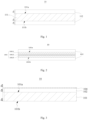
- Fig. 2 is a structural schematic diagram of a composite current collector 10 with a support layer 101 having a composite structure according to another embodiment of the present disclosure.
- the support layer 101 has a composite layer structure formed by stacking a first sub-layer 1011, a second sub-layer 1012 and a third sub-layer 1013.
- the support layer 101 having the composite layer structure has a first surface 101a and a second surface 101b that are opposite to each other, and the conductive layers 102 are stacked on the first surface 101a and the second surface 101b of the support layer 101. It is also possible that the conductive layer 102 is disposed only on the first surface 101a of the support layer 101, or only on the second surface 101b of the support layer 101.
- the two or more layers each can be made of the same material or different materials.
- the composite current collector 10 can further include a protective layer.
- the protective layer may include a first protective layer 103 disposed between the conductive layer 102 and the support layer 101; and/or a second protective layer 104 disposed on the surface of the conductive layer 102 facing away from the support layer 101.
- the protective layer can protect the conductive layer 102 from chemical corrosion, mechanical damage, or other damage, and make sure that the composite current collector 10 has high operating stability and long service life, thereby improving the safety performance and electrochemical performance of the lithium ion secondary battery.
- the protective layer can also enhance the strength of the composite current collector 10.
- Fig. 3 to Fig. 5 illustrate that merely one surface of the support layer 101 is provided with the conductive layer 102 and the protective layer.
- the two opposite surfaces of the conductive layer 102 each can be provided with the conductive layer 102.
- the first protective layer 103 and the second protective layer 104 independently include one or more of metal, metal oxide, and conductive carbon.
- the protective layer made of the metallic material is a metal protective layer
- the protective layer made of the metal oxide material is a metal oxide protective layer
- the metal is, for instance, one or more of nickel, chromium, nickel-based alloy, and copper-based alloy.
- the aforementioned nickel-based alloy is an alloy composed of pure nickel as a matrix, and one or more other elements, and nickel-chromium alloy is preferred.
- the nickel-chromium alloy is an alloy of metal nickel and metal chromium.
- the nickel-chromium alloy has a weight ratio of nickel to chromium of 1:99 to 99:1, such as 9:1.
- the aforementioned copper-based alloy is an alloy composed of pure copper as a matrix, and one or more other elements, and nickel-copper alloy is preferred.
- the nickel-copper alloy has a weight ratio of nickel to copper of 1:99 to 99:1, such as 9:1.
- the above metal oxide is, for example, one or more of aluminum oxide, cobalt oxide, chromium oxide, and nickel oxide.
- the conductive carbon is, for example, one or more of graphite, superconductive carbon, acetylene black, carbon black, ketjen black, carbon dots, carbon nanotubes, graphene, and carbon nanofiber. Further, the conductive carbon is one or more of carbon black, carbon nanotubes, acetylene black, and graphene.
- the composite current collector 10 includes the support layer 101, the conductive layer 102, and the protective layer 103 which are disposed in a stacked manner.
- the support layer 101 has the first surface 101a and the second surface 101b that are opposite to each other in the thickness direction of the support layer 101, the conductive layer 102 is stacked on at least one of the first surface 101a and the second surface 101b of the support layer 101, and the second protective layer 104 is stacked on the surface of the conductive layer 102 facing away from the support layer 101.
- the second protective layer 104 which is simply referred to as an upper protective layer hereinafter, protects the conductive layer 102 from chemical corrosion and mechanical damage, and also modifies the interface between the composite current collector 10 and the active material layer, thereby increasing the bonding force between the composite current collector 10 and the active material layer.
- the second protective layer 104 is preferably at least one of the metal protective layer or the metal oxide protective layer.
- the metal oxide protective layer and the metal protective layer have high mechanical strength, high corrosion resistance, and large specific surface area, which can better protect the conductive layer 102 from the chemical corrosion or mechanical damage, and can further increase the interface bonding force between the conductive layer 102 and an active material layer, thereby improving the performances of the lithium ion secondary battery.
- the second protective layer 104 is the metallic protective layer, for example, aluminum oxide, chrome oxide, nickel oxide, chromium oxide, and the like.
- the metal oxide protective layer has greater hardness and mechanical strength, larger specific surface area, and better corrosion resistance, which can better protect the conductive layer 102 and improve the safety performance of the battery during nailing.
- the second protective layer 104 is the metallic protective layer.
- the metallic protective layer may increase the conductivity of the composite current collector 10, and reduce the polarization of the battery, thereby lowering the risk of lithium precipitation and improving the cycle and safety performances of the lithium ion secondary battery.
- the second protective layer 104 is a two-layered protective layer, i.e., a composite structure including one metallic protective layer and one metal oxide protective layer.
- the metallic protective layer is disposed on the surface of the conductive layer 102 facing away from the support layer 101 and the metal oxide protective layer is disposed on a surface of the metallic protective layer facing away from the support layer 101. In this way, the conductivity and corrosion resistance of the negative current collector, and the interface between the conductive layer 102 and the negative active material layer can be improved both, thereby obtaining the negative current collector having better overall performances.
- the composite current collector 10 includes the support layer 101, the conductive layer 102 and the protective layer 103 that are stacked.
- the support layer 101 in a thickness direction thereof, has the first surface 101a and the second surface 101b that are opposite to each other, the conductive layer 102 is stacked on at least one of the first surface 101a and the second surface 101b of the support layer 101, and the first protective layer 103 is stacked between the conductive layer 102 and the support layer 101.
- the first protective layer 103 which is also referred to as a lower protective layer, protects the conductive layer 102 from chemical corrosion and mechanical damage, and also increases the bonding force between the support layer 101 and the conductive layer 102, thereby preventing the detachment between the support layer 101 and the conductive layer 102 and improving the support and protective effect on the conductive layer 102.
- the first protective layer 103 is the metal oxide protective layer or the metal protective layer.
- the metal oxide protective layer and the metal protective layer have better corrosion resistance and larger specific surface area, and further increases the bonding force between the support layer 101 and the conductive layer 102. Therefore, the first protective layer 103 can provide the conductive layer 102 with better protective effect, and improve the performances of the lithium ion secondary battery.
- the metal oxide protective layer has greater hardness and better mechanical strength, and thus is more advantageous to improving the strength of the composite current collector 10.
- the first protective layer 103 is the metal oxide protective layer.
- the first protective layer 103 is the metallic protective layer.
- Such a first protective layer 103 can protect the conductive layer 102 from the chemical corrosion or mechanical damage as well as increase the conductivity of the composite current collector 10, and reduce the polarization of the battery, thereby lowering the risk of lithium precipitation and improving the cycle and safety performances of the lithium ion secondary battery.
- the composite current collector 10 includes the support layer 101, the conductive layer 102 and the protective layers 103 that are stacked.
- the support layer 101 in a thickness direction thereof, has the first surface 101a and the second surface 101b that are opposite to each other, the conductive layer 102 is stacked on at least one of the first surface 101a and the second surface 101b of the support layer 101, and the first protective layer 103 is stacked between the conductive layer 102 and the support layer 101 and the second protective layer 104 is stacked on a surface of the conductive layer 102 facing away from the support layer 101.
- the protective layers being disposed on both surfaces of the conductive layer 102 can sufficiently protect the conductive layer 102, such that the composite current collector 10 can have higher overall performances.
- first protective layers 103 and the second protective layer 104 disposed on both surfaces of the conductive layer 102 can be made of the same material or different materials, and have the same or different thickness.
- the first protective layer 103 when the composite current collector 10 includes the first protective layer 103, the first protective layer 103 has a thickness D b that satisfies 1 nm ⁇ D b ⁇ 200nm, and D b ⁇ 0.1D 1 .
- the thickness D b of the first protective layer 103 can be smaller than or equal to 200nm, 180nm, 150nm, 120nm, 100nm, 80nm, 60nm, 55nm, 50nm, 45nm, 40nm, 30nm, or 20nm, and the thickness D b of the first protective layer 103 can be further greater than or equal to 1nm, 2nm, 5nm, 8nm, 10nm, 12nm, 15nm, or 18nm.
- the thickness D b of the first protective layer 103 satisfies 5nm ⁇ D b ⁇ 200nm, and more preferably 10nm ⁇ D b ⁇ 200nm.
- the first protective layer 103 When thickness of the first protective layer 103 falls within an appropriate range, the first protective layer 103 has the protective effect on the conductive layer 102 and allows the lithium ion secondary battery to have higher energy density.
- the second protective layer 104 when the composite current collector 10 includes the second protective layer 104, the second protective layer 104 has a thickness D a satisfying 1nm ⁇ D a ⁇ 200nm and D a ⁇ 0.1D 1 .
- the thickness D a of the second protective layer 104 can be smaller than or equal to 200nm, 180nm, 150nm, 120nm, 100nm, 80nm, 60nm, 55nm, 50nm, 45nm, 40nm, 30nm, or 20nm, and the thickness D a of the second protective layer 104 can be further greater than or equal to 1nm, 2nm, 5nm, 8nm, 10nm, 12nm, 15nm, or 18nm.
- the thickness D a of the second protective layer 104 satisfies 5nm ⁇ D a ⁇ 200nm, and more preferably 10nm ⁇ D a ⁇ 200nm.
- the second protective layer 104 When thickness of the second protective layer 104 falls within an appropriate range, the second protective layer 104 has the protective effect on the conductive layer 102 and allows the lithium ion secondary battery to have higher energy density.
- the composite current collector 10 includes the first protective layer 103 and the second protective layer 104
- D a >D b is conducive to protecting the the conductive layers 102 from the chemical corrosion or mechanical damage by synergistic effect of the first protective layer 103 and the second protective layer 104 and also is conducive to allowing the lithium ion secondary battery to have the higher energy density.
- the first protective layer 103 and the second protective layer 104 can exert better cooperative protective effect when 0.5D a ⁇ D b ⁇ 0.8D a .
- first protective layer 103 and the second protective layer 104 has an ignorable influence on the thermal conductivity of the composite current collector 10.
- the bonding force between the support layer 101 and the conductive layer 102 satisfies F is 100N/m, and preferably F ⁇ 400N/m, such that the detachment between the support layer 101 and the conductive layer 102 can be effectively prevented and the overall strength and stability can be enhanced, thereby improving the performances of the lithium ion secondary battery.
- the conductive layer 102 adopting the metallic material can be formed on the support layer 101 by at least one method of mechanical rolling, bonding, vapor deposition, electroless plating, or electroplating.
- the vapor deposition method or the electroplating method is preferred.
- the conductive layer 102 being formed on the support layer 101 by the vapor deposition method or the electroplating method is conducive to achieving a tighter bonding between the conductive layer 102 and the support layer 101.
- the said vapor deposition method is physical vapor deposition.
- the physical vapor deposition is at least one of evaporation method and sputtering method.
- the evaporation method is at least one of vacuum evaporating, thermal evaporation deposition, and electron beam evaporation method (EBEM).
- the sputtering method is magnetron sputtering.
- the conductive layer 102 is formed by mechanical rolling as follows: placing a metal foil on mechanical rollers and rolling the metal foil to have a predetermined thickness under a pressure of 20t to 40t; placing the metal foil onto the cleaned surface of the support layer 101 and placing them on the mechanical rollers; and rolling them until they are tightly bonded under a pressure of 30t to 50t.
- the conductive layer 102 is formed by bonding as follows: placing a metal foil on mechanical rollers and rolling the metal foil to have a predetermined thickness under a pressure of 20t to 40t; coating the cleaned surface of the support layer 101 with a mixed solution of polyvinylidene fluoride (PVDF) and N-methylpyrrolidone (NMP); and finally, bonding the conductive layer 102 having the predetermined thickness to the surface of the support layer 101, following by drying, until they are tightly bonded.
- PVDF polyvinylidene fluoride
- NMP N-methylpyrrolidone
- the conductive layer 102 is formed by vacuum evaporation as follows: placing the surface-cleaned support layer 101 in a vacuum plating chamber, evaporating a high-purity metal wire in a metal evaporating chamber at a high temperature of 1300°C to 2000°C, and depositing the evaporated metal on the support layer 101 after the evaporated metal passing through a cooling system in the vacuum plating chamber, so as to form a conductive layer 102.
- the conductive layer 102 adopting the carbon-based conductive material can be formed on the support layer 101 by at least one method of mechanical rolling, bonding, vapor deposition, in-situ formation, and coating.
- the conductive layer 102 adopting the conductive polymer material can be formed on the support layer 101 by at least one method of mechanical rolling, bonding, in-situ formation, and coating.
- the protective layer can be formed on the conductive layer 102 by at least one of vapor deposition method, in-situ formation method, and coating method.
- the vapor deposition method can be that as described above.
- the in-situ formation method is preferably an in-situ passivation method, i.e., a metal oxide passivation layer is formed in situ on a metal surface.
- the coating method is at least one of roll coating, extrusion coating, blade coating, and gravure coating.
- the protective layer is formed on the conductive layer 102 by at least one of the vapor deposition method and the in-situ formation method, thereby increasing the bonding force between the conductive layer 102 and the protective layer 103. Therefore, the protective layer 102 can better protect the negative current collector 10 and ensure the working performance of the negative current collector 10.
- the composite current collector 10 according to any one the aforementioned embodiments can be used as the positive current collector and/or the negative current collector.
- the positive current collector is a metallic current collector such as an aluminum foil or an aluminum alloy current collector, or the above-mentioned composite current collector 10, and the negative current collector is the composite current collector 10.
- the composite current collector 10 By replacing the conventional copper foil negative current collector having a greater density with the composite current collector 10, both the weight energy density and the low-temperature performance of the lithium ion secondary battery can be improved.
- the composite current collector 10 at the negative electrode plate the lithium precipitation at the negative electrode can be prevented while improving the low-temperature performance of the lithium ion secondary battery, thereby improving the dynamic performance, rate performance and safety performance of the lithium ion secondary battery.
- both the positive current collector and the negative current collector are the composite current collector 10
- the low-temperature performance of the lithium ion secondary battery can be further improved.
- the thickness D 1 of the conductive layer 102 and the thickness D 2 of the support layer 101 can be measured by instruments and methods well known in the related art, for example, using a micrometer.
- the thermal conductivity of the composite current collector 10 can be measured using instruments and methods well known in the related art, such as using a thermal conductivity meter.
- the measurement includes: cutting a composite current collector 10 into samples with 5cm ⁇ 5cm, and measuring the thermal conductivity of the sample by using a TC3000 type thermal conductivity meter.
- the sheet resistance R S of the conductive layer 102 can be measured by the four-probe method with a RTS-9 type double electric four-probe tester.
- the test environment is: room temperature 23 ⁇ 2°C, normal pressure of 0.1 MPa, relative humidity ⁇ 65%.
- the sample of the positive current collector 10 is surface cleaned, then placed horizontally on a test board, the probes are placed to be in good contact with the surface of the conductive layer 102 of the sample, a current range of the sample is calibrated in an automatic test mode, and then at an appropriate current range, the sheet resistance is measured. Eight to ten data points of the same sample are collected for sake of data measurement accuracy and error analysis, and the average is recorded as the sheet resistance of the conductive layer 102.
- the Young's modulus E of the support layer 101 can be determined by a method known in the related art.
- the support layer 101 is cut into a sample of 15 mm ⁇ 200 mm, and the thickness h ( ⁇ m) of the sample is measured by a micrometer, and a tensile test is performed by using a tensile machine (such as Instron 3365 tensile machine, Instron, USA) at room temperature and normal pressure (25°C, 0.1MPa).
- a tensile machine such as Instron 3365 tensile machine, Instron, USA
- An initial position is set in such manner that the sample between clamps has a length of 50mm, and the tensile speed is 5 mm/min.
- the bonding force F between the support layer 101 and the conductive layer 102 can be measured by a method known in the related art.
- the composite current collector 10 in which the conductive layer 102 is disposed on one surface of the support layer 101, is used as a sample to be tested.
- the sample has a width d of 0.02m.
- Under room temperature and normal pressure (25°C, 0.1MPa) a 3M double-sided adhesive tape is evenly attached to a stainless steel plate, the sample is then evenly attached to the double-sided adhesive tape, and then the conductive layer 102 is continuously peeled off from the support layer 101 at 180° by using a tensile machine (such as Instron 3365 tensile machine, Instron, USA) at a speed of 50 mm/min.
- the maximum tensile force x(N) is read according to the data diagram of the tensile force and the displacement, and the bonding force F (N/m) between the conductive layer 102 and the support layer 101 is calculated according to
- the present disclosure provides a positive electrode plate for a lithium ion secondary battery.
- the positive electrode plate includes a positive current collector and a positive active material layer disposed on the positive current collector.
- the positive current collector has two opposite surfaces in a thickness direction thereof, and the positive active material layers are stacked on the two surfaces of the positive current collector. It is also possible that the positive active material layer is stacked on any one of the two surfaces of the positive current collector.
- the positive current collector is the aforementioned composite current collector; or when the negative current collector is the aforementioned composite current collector, the positive current collector is the aforementioned composite current collector or a metallic current collector such as an aluminum foil or an aluminum alloy.
- the positive current collector being the aforementioned composite current collector 10 not only can achieve the beneficial effects described above, but also may improve the safety performance of the lithium ion secondary battery.
- the positive active material layer includes a positive active material, and the positive active material can be one or more active materials known in the related art that are capable of reversible intercalation/deintercalation of ions.
- the positive active material is, for example, one or more of lithium cobalt oxide, lithium nickel oxide, lithium manganese oxide, lithium nickel manganese oxide, lithium nickel cobalt manganese oxide, lithium nickel cobalt aluminum oxide, lithium vanadium phosphate, lithium cobalt phosphate, lithium manganese phosphate, lithium iron phosphate , lithium manganese iron phosphate, lithium iron silicate, lithium vanadium silicate, lithium cobalt silicate, lithium manganese silicate, and lithium titanate.
- the positive active material is one or more of LiMn 2 O 4 , LiNiO 2 , LiCoO 2 , LiNi 1-y Co y O 2 (0 ⁇ y ⁇ 1), LiNi a Co b Al 1-a-b O 2 (0 ⁇ a ⁇ 1, 0 ⁇ b ⁇ 1, 0 ⁇ a+b ⁇ 1), LiMn 1-m-n Ni m Co n O 2 (0 ⁇ m ⁇ 1, 0 ⁇ n ⁇ 1, 0 ⁇ m+n ⁇ 1), LiCoPO 4 , LiMnPO 4 , LiFePO 4 , LiMn 1-z Fe z PO 4 (0 ⁇ z ⁇ 1), and Li 3 V 2 (PO 4 ) 3 .
- the positive active material layer can further include a binder, which is not specifically limited herein.
- the binder is one or more of styrene butadiene rubber (SBR), water-based acrylic resin, carboxymethyl cellulose sodium (CMC-Na), polyvinylidene fluoride (PVDF), polytetrafluoroethylene (PTFE), ethylene-vinyl acetate copolymer (EVA), polyvinyl alcohol (PVA), and polyvinyl butyral (PVB).
- SBR styrene butadiene rubber
- CDM-Na carboxymethyl cellulose sodium
- PVDF polyvinylidene fluoride
- PTFE polytetrafluoroethylene
- EVA ethylene-vinyl acetate copolymer
- PVB polyvinyl butyral
- the positive active material layer can further include a conductive agent, which is not specifically limited herein.
- the conductive agent is one or more of graphite, superconductive carbon, acetylene black, carbon black, ketjen black, carbon dots, carbon nanotubes, graphene, and carbon nanofiber.
- the positive active material layer has a thickness T 1 in a range of 50 ⁇ m to 100 ⁇ m.
- the thickness T 1 of the positive active material layer falls within the above range, the positive active material layer has better effect on improving the performances at low temperature of the lithium ion secondary battery, and makes sure that the positive electrode has good dynamic performance, thereby improving the electrochemical performance of the lithium ion secondary battery.
- the thickness T 1 of the positive active material layer is in a range of 60 ⁇ m to 90 ⁇ m, which can further improve the performances at low temperature of the lithium ion secondary battery, thereby obtaining the positive electrode plate and the lithium ion secondary battery having good overall performance.
- the "thickness T 1 of the positive active material layer” is a thickness of the positive active material layer on one side of the positive current collector.
- the positive electrode plate can be prepared according to a conventional method in the related art, such as a coating method.
- the positive active material, as well as optionally a conductive agent and a binder are dispersed in a solvent such as N-methylpyrrolidone (NMP), so as to form a uniform positive slurry.
- NMP N-methylpyrrolidone
- the positive slurry is coated on a positive current collector, followed by drying, thereby obtaining a positive electrode plate.
- the present disclosure provides a negative electrode plate for a lithium ion secondary battery.
- the negative electrode plate includes a negative current collector and a negative active material layer disposed on the negative current collector.
- the negative current collector has two opposite surfaces in a thickness direction thereof, and the negative active material layer is disposed on the two surfaces of the negative current collector. It is also possible that the negative active material layer is disposed on any one of the two surfaces of the negative current collector.
- the positive current collector is the metallic current collector
- the negative current collector is the aforementioned composite current collector; or when the positive current collector is the aforementioned composite current collector, the negative current collector is the aforementioned composite current collector or metallic current collector, such as copper foil or copper alloy.
- the negative current collector being the composite current collector as described above also ha has the same beneficial effects, which are not repeated herein.
- the negative active material layer includes a negative active material, and the negative active material can be one or more active materials known in the related art that are capable of reversible intercalation/deintercalation of ions, which are not specifically limited herein.
- the negative active material is, for example, one or more of lithium metal, natural graphite, artificial graphite, mesophase carbon microbead (abbreviated as MCMB), hard carbon, soft carbon, silicon, silicon-carbon composite, SiO, Li-Sn alloy, Li-Sn-O alloy, Sn, SnO, SnOz, spinel-structured lithium titanate, and a Li-Al alloy.
- the negative active material layer can further include a conductive agent, which is not specifically limited herein.
- the conductive agent may include one or more of graphite, superconductive carbon, acetylene black, carbon black, ketjen black, carbon dots, carbon nanotubes, graphene, and carbon nanofiber.
- the negative active material layer 201 can further include a binder, which is not specifically limited herein.
- the binder may include one or more of styrene butadiene rubber (SBR), water-based acrylic resin, carboxymethyl cellulose sodium (CMC-Na), polyvinylidene fluoride (PVDF), polytetrafluoroethylene (PTFE), ethylene-vinyl acetate copolymer (EVA), polyvinyl alcohol (PVA), and polyvinyl butyral (PVB).
- SBR styrene butadiene rubber
- CDM-Na carboxymethyl cellulose sodium
- PVDF polyvinylidene fluoride
- PTFE polytetrafluoroethylene
- EVA ethylene-vinyl acetate copolymer
- PVB polyvinyl butyral
- the negative active material layer has a thickness T 2 in a range of 30 ⁇ m to 70 ⁇ m.
- the thickness T 2 of the negative active material layer falls within the above range, the negative active material layer has better effect on improving the performances at low temperature of the lithium ion secondary battery while making sure that the negative electrode has good dynamic performance, thereby improving the electrochemical performance of the lithium ion secondary battery.
- the thickness T 2 of the negative active material layer is in a range of 40 ⁇ m to 60 ⁇ m, which can further improve the performances at low temperature of the lithium ion secondary battery, thereby obtaining the negative electrode plate and the lithium ion secondary battery having good overall performance.
- the "thickness T 2 of the negative active material layer” is a thickness of the negative active material layer on one side of the negative current collector.
- the negative electrode plate can be prepared according to a conventional method known in the related art, such as a coating method.
- the negative active material, as well as optionally a conductive agent and a binder are dispersed in a solvent such as deionized water, so as to form a uniform negative slurry.
- the negative slurry is coated on a negative current collector followed by drying, thereby obtaining a negative electrode plate.
- the present disclosure further provides an electrolytic solution of a lithium ion secondary battery.
- the electrolytic solution includes an organic solvent and an electrolytic salt dispersed in the organic solvent.
- the organic solvent of the lithium ion secondary battery can include one or more of ethylene carbonate (EC), propylene carbonate (PC), pentylene carbonate, 1,2-butanediol carbonate (1,2-BC), 2,3-butanediol carbonate (2,3-BC), ethyl methyl carbonate (EMC), diethyl carbonate (DEC), dimethyl carbonate (DMC), dipropyl carbonate (DPC), methyl propyl carbonate (MPC), ethyl propyl carbonate (EPC), butylene carbonate (BC), fluoroethylene carbonate (FEC), methyl formate (MF), ethyl methanoate (EM), methyl acetate (MA), ethyl acetate (EA), propyl acetate (PA), methyl propionate (MP), ethyl propionate (EP), propyl propionate (PP), methyl butyrate (MB), ethyl butyrate (EB),
- the organic solvent is a mixed solvent including a cyclic carbonate and a chain carbonate.
- Such an organic solvent is advantageous for preparing an electrolytic solution having excellent comprehensive properties such as conductivity and viscosity.
- the electrolytic solution has a conductivity at 25°C of 8mS/cm to 11mS/cm.
- the electrolytic solution can have good ion-conducting dynamic performance and thermal stability both. Therefore, the battery can have relatively high cycle performance at normal temperature and at low temperature, as well as at high temperature.
- the electrolytic salt of the lithium ion secondary battery can include one or more of LiPF 6 (lithium hexafluorophosphate), LiBF 4 (lithium tetrafluoroborate), LiClO 4 (lithium perchlorate), LiAsF 6 (lithium hexafluoroarsenate), LiFSI (lithium bisfluorosulfonylmide), LiTFSI (lithium bis(fluorosulfonyl)imide), LiTFS (lithium trifluoromethanesulfonate), LiDFOB (lithium difluoro(oxalate)borate), LiBOB (lithium bis(oxalate)borate), LiPO 2 F 2 (lithium difluorophosphate), LiDFOP (lithium difluorodioxalate phosphate), and LiTFOP (lithium tetrafluorooxalate phosphate).
- LiPF 6 lithium hexafluorophosphate
- LiBF 4 lithium tetra
- the electrolytic solution can further include an additive.
- the additive may include a negative electrode film-forming additive, and may also include a positive film-forming additive, and may also include an additive capable of improving certain properties of the battery, such as an additive for improving overcharge performance of the battery, an additive for improving high temperature performance, an additive for improving low temperature performance of the battery, and the like.
- the separator is not specifically limited in the present disclosure, and can be any well-known porous separator having good chemical stability and mechanical stability, such as one or more of glass fiber, non-woven fabric, polyethylene, polypropylene, or polyvinylidene fluoride.
- the separator can be a single layer film or a multilayer composite film. When the separator is the multilayer composite film, each layer can be made of the same or different material.
- the separator can also be a composite separator, such as a composite separator having an inorganic coating on a surface of an organic separator.
- the separator has a porosity in a range of 30% to 50%, and preferably 35%-45%, which can further improve the dynamic performance of the lithium ion secondary battery, and is conducive to improving the low temperature performance of the lithium ion secondary battery.
- the battery adopting such a separator can have higher energy density.
- the lithium ion secondary battery may include an outer package for encapsulating the positive electrode plate, the negative electrode plate, and the electrolytic solution.
- the positive electrode plate, the negative electrode plate, and the separator may be stacked or wound to form a battery core having a stacked structure or a battery core having a wound structure, and the battery core is encapsulated in the outer package.
- the electrolytic solution is impregnated in the battery core.
- the outer package of the battery may be a soft package, such as a pouch.
- the material of the soft package may be plastic, such as one or more of polypropylene PP, polybutylene terephthalate PBT, polybutylene succinate PBS, and the like.
- the outer package of the battery may also be a hard package, such as an aluminum casing.
- the shape of the battery is not particularly limited in the present disclosure, and may be cylindrical, square, or any other shape.
- Fig. 6 illustrates a lithium ion secondary battery 5 having a rectangular structure as an example.
- the lithium ion secondary battery can be assembled into a battery module.
- the battery module may include a plurality of lithium ion secondary batteries, and the specific number can be adjusted according to the application and capacity of the battery module.
- Fig. 7 illustrates a battery module 4 as an example.
- a plurality of lithium ion secondary batteries 5 are sequentially arranged along a length direction of the battery module 4. It is also possible that a plurality of lithium ion secondary batteries 5 convenientlye arranged in any other manner. Further, a plurality of lithium ion secondary batteries 5 can be fixed by a fastener.
- the battery module 4 may further include a casing having a receiving space, in which a plurality of lithium ion secondary batteries 5 are received.
- the above battery module can also be assembled into a battery pack, and the number of battery modules included in the battery pack can be adjusted according to the application and capacity of the battery pack.
- Fig. 8 and Fig. 9 illustrate a battery pack 1 as an example.
- the battery pack 1 may include a battery box and a plurality of battery modules 4 provided in the battery box.
- the battery box includes an upper box 2 and a lower box 3 and the upper box 2 is arranged to cover the lower box 3, so as to form a closed space for receiving the battery modules 4.
- a plurality of battery modules 4 can be arranged in the battery box in any manner.
- the present disclosure provides an apparatus including one or more lithium ion secondary batteries according to the present disclosure.
- the lithium ion secondary battery may be used as a power source of the apparatus or as an energy storage unit of the apparatus.
- the apparatus may be, but is not limited to, a mobile apparatus (such as a mobile phone, a notebook computer, and the like), an electric vehicle (such as a pure electric vehicle, a hybrid electric vehicle, a plug-in hybrid electric vehicle, an electric bicycle, an electric scooter, and an electric golf vehicles, electric trucks, and the like), electric trains, ships and satellites, energy storage systems, or the like.
- the apparatus can adopt different electrochemical devices, such as a battery, a battery module, or a battery pack, according to application requirements.
- Fig. 10 illustrates an apparatus as an example.
- the apparatus is a pure electric vehicle, a hybrid electric vehicle, or a plug-in hybrid electric vehicle.
- a battery pack or a battery module can be used.
- the apparatus may be a mobile phone, a tablet computer, a notebook computer, and the like.
- the apparatus is generally required to be thin and light, and a secondary battery can be used as a power source.
- a positive active material lithium iron phosphate, referred to as LFP; or LiNi 1/3 Co 1/3 Mn 1/3 O 2 , referred to as NCM333), PVDF as binder, and acetylene black as conductive agent were mixed in a weight ratio of 93:2:5, and then N-methylpyrrolidone (NMP) was added; the mixture was thoroughly and uniformly stirred in a vacuum mixer to obtain a positive slurry; the positive slurry was then coated on an aluminum foil, which was used as a positive current collector, followed by drying, cold pressing and cutting, thereby obtaining a conventional positive electrode plate.
- the conventional positive electrode plate had a compaction density of 2.4g/cm 3 .
- the positive electrode plate was prepared in a similar process as that of the conventional positive electrode plate with the exception that, the positive current collector was a composite current collector.
- the composite current collector was prepared by vacuum evaporation including selecting a polymer-based support layer having a predetermined thickness and performing surface cleaning on the support layer; placing the surface-cleaned support layer in a vacuum plating chamber; evaporating a high-purity aluminium wire in a metal evaporating chamber at a high temperature of 1300°C to 2000°C; and depositing the evaporated metal on both surfaces of the support layer after the evaporated metal passing through a cooling system in the vacuum plating chamber, so as to form conductive layers.
- Graphite as a negative active material, acetylene black as a conductive agent, CMC-Na as a thickener, and SBR as binder were mixed in a weight ratio of 97:1:1:1, and then deionized water was added; the mixture was thoroughly and uniformly stirred in a vacuum mixer to obtain negative slurry; the negative slurry was then uniformly coated on a copper foil, which was used as a negative current collector, followed by drying, cold pressing and cutting, thereby obtaining a conventional negative electrode plate.
- the conventional negative electrode plate had a compaction density of 1.7g/cm 3 .
- the negative electrode plate was prepared in a similar process as that of the conventional negative electrode plate with the exception that, the negative current collector is a composite current collector.
- the composite current collector was prepared by vacuum evaporation including: selecting a polymer-based support layer having a predetermined thickness and performing surface cleaning on the support layer; placing the surface-cleaned support layer in a vacuum plating chamber; evaporating a high-purity copper wire in a metal evaporating chamber at a high temperature of 1300°C to 2000°C; and depositing the evaporated metal on both surfaces of the support layer after the evaporated metal passing through a cooling system in the vacuum plating chamber, so as to form conductive layers.
- the organic solvent was a mixed solvent of ethylene carbonate (EC), ethyl methyl carbonate (EMC), diethyl carbonate (DEC), dimethyl carbonate (DMC), and methyl propionate (MP).
- the electrolytic salt was LiPF 6 . LiPF 6 is present in the electrolytic solution in a mass percentage of 12.5wt%.
- the positive electrode plate, the negative electrode plate and the separator were winded to obtain a battery core, the battery core was placed into a package case, then the electrolytic solution was injected and the package case was sealed, and a lithium ion secondary battery was obtained after being subjected to standing, compaction, formation, venting, and the like.
- the lithium ion secondary battery was first discharged to 1C to the lower limit of a charge and discharge cutoff voltage, then charged at 1C constant current to the upper limit of the charge and discharge cutoff voltage, then charged at a constant voltage until the current was 0.05C, and a charging capacity CC was recorded.
- the ambient temperature of the battery was adjusted to -10°C, and the battery was discharged with 1 C constant current to the lower limit of the charge and discharge cutoff voltage, and a discharge capacity CD was recorded.
- the ratio of the discharge capacity CD to the charge capacity CC is the discharge capacity retention of the lithium ion secondary battery at -10°C.
- Discharge capacity retention ratio (%) of lithium ion secondary battery at -10°C CD/CC ⁇ 100%.
- the lithium ion secondary battery was first discharged to 1C to the lower limit of the charge and discharge cutoff voltage, then the ambient temperature of the battery was increased to 60°C, and the battery was charged at 1C constant current to the upper limit of the charge and discharge cutoff voltage and then charged at constant voltage until the current was 0.05C; and after that, the battery was discharged with 1 C constant current to the lower limit of the charge and discharge cutoff voltage.
- the above process is one charge and discharge cycle. 500 times of the above charge and discharge cycles were performed on the battery, and a discharge capacity for the 500 th cycle of the lithium ion secondary battery at 60°C was recorded.
- Capacity retention ratio (%) of lithium ion secondary battery after 500 cycles at 60°C discharge capacity for 500 th cycle / discharge capacity for 1 st cycle.
- the charge and discharge cutoff voltage of the lithium ion secondary battery in which LFP was as the positive active material was in a range of 2.0V to 3.6V; and the charge and discharge cutoff voltage of the lithium ion secondary battery in which NCM333 is used as the positive active material was in a range of 2.8V to 4.2V
- the weight percentage of the positive current collector was a percentage of a weight per unit area of the positive current collector to a weight per unit area of the conventional positive current collector.
- the weights of all positive current collectors adopting the composite current collectors were reduced to different extents, thereby increasing the weight energy density of the battery.
- the weight percentage of the negative current collector was a percentage of a weight per unit area of the negative current collector to a weight per unit area of the conventional negative current collector.
- the weights of all negative current collectors adopting the composite current collectors were reduced to different extents, thereby increasing the weight energy density of the battery.
- each negative active material layer had a thickness of 52 ⁇ m
- each positive active material layer had a thickness ⁇ f 74 ⁇ m. It was shown from the data in Table 2-2 that the low temperature performance of the lithium ion secondary battery was improved when the thermal conductivity of the composite current collector was within the range of 0.01W/(m•K) to 10W/(m•K).
- the positive active material of each positive active material layer was LFP, and the negative active material of each negative active material layer was graphite. It was shown from the data in Table 3 that the lithium ion secondary battery according to the present disclosure exhibited much better low temperature performance when the thickness T 1 of the positive active material layer was within the range of 50 ⁇ m to 100 ⁇ m; and the low temperature performance of the lithium ion secondary battery was further improved when the thickness T 1 of the positive active material layer was within a range of 60 ⁇ m to 90 ⁇ m.
- the lithium ion secondary battery according to the present disclosure exhibited much better low temperature performance when the thickness T 2 of the negative active material layer was within the range of 30 ⁇ m to 70 ⁇ m; and the low temperature performance of the lithium ion secondary battery was further improved when the thickness T 2 of the negative active material layer was within a range of 40 ⁇ m to 60 ⁇ m.
- the protective layer was disposed on the positive current collector 2-3.
- Table 4-2 Battery No. Positive current collector Positive active material Negative current collector Negative active material Capacity retention ratio after 500 cycles at 60°C (%) Battery 9 Positive current collector 2-3 NCM333 Negative current collector 2-4 Graphite 80 Battery 9-1 Positive current collector 2-3-1 NCM333 Negative current collector 2-4 Graphite 81 Battery 9-2 Positive current collector 2-3-2 NCM333 Negative current collector 2-4 Graphite 82 Battery 9-3 Positive current collector 2-3-3 NCM333 Negative current collector 2-4 Graphite 81 Battery 9-4 Positive current collector 2-3-4 NCM333 Negative current collector 2-4 Graphite 82 Battery 9-5 Positive current collector 2-3-5 NCM333 Negative current collector 2-4 Graphite 83 Battery 9-6 Positive current collector 2-3-6 NCM333 Negative current collector 2-4 Graphite 84
- each negative active material layer had a thickness of 52 ⁇ m, and each positive active material layer had a thickness of 74 ⁇ m.
- the protective layer was disposed on the positive current collector 2-5.
- the nickel-based alloy contained 90wt% of nickel and 10wt% of chromium.
- the double protective layers included a nickel protective layer having a thickness of 30nm and disposed on the surface of the conductive layer facing away from the support layer; and a nickel oxide protective layer having a thickness of 30nm and disposed on the surface of the nickel protective layer facing away from the support layer.
- each negative active material layer had a thickness of 52 ⁇ m, and each positive active material layer had a thickness of 74 ⁇ m.
Landscapes
- Chemical & Material Sciences (AREA)
- Engineering & Computer Science (AREA)
- Chemical Kinetics & Catalysis (AREA)
- Electrochemistry (AREA)
- General Chemical & Material Sciences (AREA)
- Materials Engineering (AREA)
- Manufacturing & Machinery (AREA)
- Composite Materials (AREA)
- Physics & Mathematics (AREA)
- General Physics & Mathematics (AREA)
- Pure & Applied Mathematics (AREA)
- Algebra (AREA)
- Mathematical Analysis (AREA)
- Mathematical Optimization (AREA)
- Inorganic Chemistry (AREA)
- Condensed Matter Physics & Semiconductors (AREA)
- Cell Electrode Carriers And Collectors (AREA)
- Secondary Cells (AREA)
- Battery Electrode And Active Subsutance (AREA)
- Cell Separators (AREA)
Abstract
Description
- The present disclosure relates to the technical field of secondary batteries, and particularly, relates to a lithium ion secondary battery, a battery core, a negative electrode plate, and an apparatus.
- Lithium ion secondary batteries have been widely applied due to their advantages such as excellent charge and discharge performance, no memory effect and being environmentally friendly. However, the lithium ion secondary batteries usually have poor performances under low temperature conditions. In severe cases, lithium precipitation may occur on a negative electrode, which significantly affects electrochemical performance and safety performance of the lithium ion secondary batteries.
- In a first aspect, the present disclosure provides a lithium ion secondary battery including a battery core and an electrolytic solution, the battery core including a positive electrode plate comprising a positive current collector and a positive active material layer disposed on a surface of the positive current collector, a separator, and a negative electrode plate comprising a negative current collector and a negative active material layer disposed on a surface of the negative current collector, wherein the positive current collector and/or the negative current collector are a composite current collector, the composite current collector includes a polymer-based support layer and a conductive layer disposed on at least one surface of the support layer, and the composite current collector has a thermal conductivity in a range of 0.01W/(m•K) to 10W/(m•K), preferably in a range of 0.1 W/(m•K) to 2W/(m•K).
- In a second aspect, the present disclosure provides a battery core for a lithium ion secondary battery, including a positive electrode plate comprising a positive current collector and a positive active material layer disposed on a surface of the positive current collector, a separator, and a negative electrode plate comprising a negative current collector and a negative active material layer disposed on a surface of the negative current collector, wherein the positive current collector and/or the negative current collector are a composite current collector, the composite current collector includes a polymer-based support layer and a conductive layer disposed on at least one surface of the support layer, and the composite current collector has a thermal conductivity in a range of 0.01W/(m•K) to 10W/(m•K), preferably in a range of 0.1 W/(m•K) to 2W/(m•K).
- In a third aspect, the present disclosure provides a negative electrode plate for a lithium ion secondary battery, including a negative current collector and a negative active material layer disposed on a surface of the negative current collector wherein the negative current collector is a composite current collector, the composite current collector includes a polymer-based support layer and a conductive layer disposed on at least one surface of the support layer, and the composite current collector has a thermal conductivity in a range of 0.01 W/(m•K) to 10W/(m•K), preferably in a range of 0.1 W/(m•K) to 2W/(m•K).
- In a fourth aspect, the present disclosure provides an apparatus, which includes the lithium ion secondary battery according to the first aspect of the present disclosure.
- The lithium ion secondary battery according to the present disclosure adopts a composite current collector, the composite current collector including a polymer-based support layer and a conductive layer disposed on at least one surface of the support layer. Surprisingly, the thermal conductivity of the composite current collector is smaller than that of a conventional metal current collector. For example, an aluminum foil current collector has a thermal conductivity of 218 W/(m•K); and a copper foil current collector has a thermal conductivity of 381 W/(m•K). The battery adopting such a composite current collector is less affected by the ambient temperature when operating in a low temperature environment, and the heat generated by the battery itself is not dissipated rapidly, such that the lithium ion secondary battery in the low temperature environment can maintain a suitable working temperature inside the battery core. In this way, a low temperature dynamic performance of the battery is improved, and thus the battery has good electrochemical performance and low temperature safety performance. In addition, the composite current collector has also a lower weight than the conventional metal current collector, thereby increasing a weight energy density of the battery.
- The apparatus of the present disclosure includes the lithium ion secondary battery according to the first aspect of the present disclosure, and thus has at least the same advantages as the lithium ion secondary battery.
- In order to clearly illustrate technical solutions of embodiments of the present disclosure, drawings used in the embodiments of the present disclosure will be briefly described below, and those skilled in the related art can also obtain other drawing on basis of these drawings without any creative labor.
-
Fig. 1 is a structural schematic diagram of a composite current collector according to an embodiment of the present disclosure; -
Fig. 2 is a structural schematic diagram of a composite current collector according to another embodiment of the present disclosure; -
Fig. 3 is a structural schematic diagram of a composite current collector according to yet another embodiment of the present disclosure; -
Fig. 4 is a structural schematic diagram of a composite current collector according to yet another embodiment of the present disclosure; -
Fig. 5 is a structural schematic diagram of a composite current collector according to yet another embodiment of the present disclosure; -
Fig. 6 is a schematic diagram of a lithium ion secondary battery according to an embodiment of the present disclosure; -
Fig. 7 is a schematic diagram of a battery module according to an embodiment of the present disclosure; -
Fig. 8 is a schematic diagram of a battery pack according to an embodiment of the present disclosure; -
Fig. 9 is an exploded view ofFig. 8 ; and -
Fig. 10 is a schematic diagram of an apparatus according to an embodiment of the present disclosure - In order to clearly explain the purposes, the technical solutions and the beneficial technical effects of the present disclosure, the present disclosure will be described in detail below with reference to the embodiments. It should be understood that the embodiments described herein are merely used to illustrate the present disclosure, but not intended to limit the present disclosure.
- For the sake of brevity, the present disclosure explicitly describes some numerical ranges. However, any lower limit can be combined with any upper limit as an unspecified range; any lower limit can be combined with any other lower limit as an unspecified range, and any upper limit can be combined with any other upper limit as an unspecified range. Further, although not explicitly described, each point or single value between endpoints of a range is included in the range. Thus, each point or single value, as a lower limit or an upper limit, can be combined with any other point or single value or combined with any other lower or upper limit to form an unspecified range.
- In the description herein, it should be noted that, unless otherwise stated, the recitation of numerical ranges by "above" and "below" include all numbers within that range including the endpoints. As used herein, "a", "an", "the", "at least one", and "one or more" are used interchangeably, unless indicated otherwise and the recitation of "more" in the phrase "one or more" includes two or more.
- The above is not intended to describe all disclosed embodiments or implementations. The exemplary embodiments are described in details as below. Throughout the present disclosure, a series of embodiments provide a guidance such that these embodiments can be used in various combinations. In the present disclosure, merely the representative embodiments are presented and should not be construed as to be exhaustive.
- The present disclosure provides a lithium ion secondary battery, including a battery core and an electrolytic solution. The battery core and the electrolytic solution can be sealed in an outer packaging.
- The present disclosure further provides a battery core for a lithium ion secondary battery. The battery core includes a positive electrode plate, a separator, and a negative electrode plate. For example, the battery core may be formed by stacking or winding the positive electrode plate, the separator, and the negative electrode plate in which the separator is disposed between the positive electrode plate and the negative electrode plate for separation.
- The positive electrode plate includes a positive current collector and a positive active material layer disposed on a surface of the positive current collector, and the positive active material layer includes a positive active material. The negative electrode plate includes a negative current collector and a negative active material layer disposed on a surface of the negative current collector, and the negative active material layer includes a negative active material. The lithium ion secondary battery can be charged and discharged by reversible intercalation and de-intercalation of lithium ions between the positive active material and the negative active material.
- The positive current collector and/or the negative current collector of the battery core can be a composite current collector.
-
Fig. 1 is a structural schematic diagram of a compositecurrent collector 10 according to an embodiment of the present disclosure. Referring toFig. 1 , the compositecurrent collector 10 includes a polymer-basedsupport layer 101 and aconductive layer 102 that are stacked. Thesupport layer 101 has, in its thickness direction, afirst surface 101a and asecond surface 101b that are opposite to each other. Theconductive layer 102 is disposed on thefirst surface 101a and thesecond surface 101b of thesupport layer 101. It can be understood that theconductive layer 102 can also be disposed on thefirst surface 101a of thesupport layer 101, or thesecond surface 101b of thesupport layer 101. - In the lithium ion secondary battery according to the present disclosure, the positive current collector and/or the negative current collector of the battery core are the composite
current collector 10, the compositecurrent collector 10 includes thesupport layer 101 and theconductive layer 102 disposed on at least one surface of thesupport layer 101, and the compositecurrent collector 10 has a thermal conductivity of 0.01W/(m•K) to 10W/(m•K). Compared with a conventional metal current collector, the compositecurrent collector 10 has a significantly reduced thermal conductivity. Therefore, the battery adopting such a composite current collector is less affected by the ambient temperature when operating in a low temperature environment, and the heat generated by the battery itself is not dissipated rapidly, such that the lithium ion secondary battery in the low temperature environment can maintain a suitable working temperature inside the battery core. In this way, the dynamic performance at low temperature of the battery can be improved, and thus the battery has good electrochemical performance and safety performance at low temperature. - The composite
current collector 10 having a thermal conductivity of smaller than or equal to 10W/(m•K) ensures that the battery has good dynamic performance at low temperature, thereby effectively improving the electrochemical performance of the battery at low temperature and effectively inhibiting the lithium precipitation occurred at low temperature on the negative electrode. The compositecurrent collector 10 having a thermal conductivity of greater than or equal to 0.01W/(m•K) is conducive to allowing thesupport layer 101 to have a small thickness, thereby improving the volume energy density and the weight energy density of the battery. Preferably, the thermal conductivity of the compositecurrent collector 10 is in a range from 0.01W/(m•K) to 2W/(m•K). - The thermal conductivity of the composite
current collector 10 is influenced by the following factors: a thickness D1 of theconductive layer 102, a material of theconductive layer 102, a thickness D2 of thesupport layer 101, a material of thesupport layer 101, processing conditions for preparing the conductive layer 102 (for example, a deposition rate, a deposition temperature, a cooling rate, and the like, when theconductive layer 102 is prepared by a deposition process), a bonding force between theconductive layer 102 and thesupport layer 101, and the like. The thermal conductivity of the compositecurrent collector 10 can be improved by adjusting one or more of the above-mentioned factors. - The
support layer 101 of the compositecurrent collector 10 can provide theconductive layer 102 with effective support, and guarantee an overall strength of the compositecurrent collector 10. Thus, theconductive layer 102 has a greatly reduced thickness, and is not easy to break, compared with the conventional metal current collector such as an aluminum foil and a copper foil. Compared with the conventional metal current collector, theconductive layer 102 has a significantly reduced thickness and thesupport layer 101 has a smaller density than metal, so that the weight of the battery core and the lithium ion secondary battery can be reduced while maintaining good conductive and current collecting performances of theconductive layer 102, thereby increasing the energy density of the battery. - In some embodiments, the thickness D1 of the
conductive layer 102 satisfies 30nm≤D1≤3µm. The thickness D1 of theconductive layer 102 within the appropriate range enables theconductive layer 102 to have high conductive and current collecting performances, which can reduce impedance of the lithium ion secondary battery and reduce polarization of the battery, thereby improving the electrochemical performances of the lithium ion secondary battery. In this way, the lithium ion secondary battery has high rate performance and cycle performance. In the meantime, theconductive layer 102 is not easy to break during processing and use, such that the compositecurrent collector 10 has higher mechanical stability and operating stability, and the lithium ion secondary battery has a longer service life. - The
conductive layer 102 having a relatively low thickness D1 enables theconductive layer 102 to form less burrs in an abnormal case of the lithium ion secondary battery such as nailing penetration, thereby reducing the risk of the metal burrs and the electrode being contacted and thereby further improving the safety performance of the lithium ion secondary battery. - In addition, disposing the
conductive layer 102 having a smaller thickness on the surface of thesupport layer 101 can significantly reduce the weight of the compositecurrent collector 10, which is conducive to reducing the weight of the lithium ion secondary battery and significantly improving the energy density of the lithium ion secondary battery. In some embodiments, the thickness D1 of theconductive layer 102 can be smaller than or equal to 3 µm, 2.5µm, 2µm, 1.8µm, 1.5µm, 1.2µm, 1µm, 900nm, 750nm, 450nm, 250nm, or 100nm; and the thickness D1 of theconductive layer 102 can be further larger than or equal to 30nm, 80nm, 100nm, 150nm, 300nm, 400nm, 600nm, 800nm, 1µm, or 1.6µm. Preferably, the thickness D1 of theconductive layer 102 satisfies 300nm≤D1≤2µm, more preferably 500nm ≤D1≤1.5µm, especially preferably 800nm≤ D1≤1.2µm. - The "thickness D1 of the
conductive layer 102" is referred to a thickness of theconductive layer 102 on one surface of thesupport layer 101. - The
conductive layer 102 can include one or more of a metallic material, a carbon-based conductive material, and a conductive polymer material. - In some embodiments, the metallic material can includes one or more of aluminum, aluminum alloy, copper, copper alloy, nickel, nickel alloy, iron, iron alloy, titanium, titanium alloy, silver, and silver alloy, for example one or more of aluminum, copper, nickel, iron, titanium, silver, nickel-copper alloy and aluminum-zirconium alloy.
- In some embodiments, the carbon-based material can include one or more of graphite, superconductive carbon, acetylene black, carbon black, ketjen black, carbon dots, carbon nanotubes, graphene, and carbon nanofiber.
- In some embodiments, the conductive polymer material can include one or more of polysulfide nitride, an aliphatic conjugated polymer, an aromatic cyclic conjugated polymer, or an aromatic heterocyclic conjugated polymer. For example, the conductive polymer material can comprise one or more of polyacetylene, polyphenylene, polypyrrole, polyaniline, polythiophene, and polypyridine. It is also possible to intensify the electron delocalization of the conductive polymer material by doping modification, thereby improving the electrical conductivity of the conductive polymer material.
- In some embodiments, when the composite
current collector 10 is used as a positive current collector, theconductive layer 102 preferably includes aluminum or aluminum alloy, and the element aluminum is present in the aluminum alloy in a weight percentage of greater than or equal to 80wt%, preferably greater than or equal to 90wt%. In some embodiments, when the compositecurrent collector 10 is used as a negative current collector, theconductive layer 102 preferably includes copper or copper alloy, and the element copper is present in the copper alloy in a weight percentage of greater than or equal to 80wt%, preferably greater than or equal to 90wt%. - In some embodiments, the
conductive layer 102 has a volume resistivity smaller than or equal to 8.0×10⁻⁸ Ω·m, which is conducive to making theconductive layer 102 to have good conductive and current collecting performances, thereby improving the rate performance and cycle performance of the lithium ion secondary battery. - Further, when the composite
current collector 10 is used as the positive current collector, the volume resistivity of theconductive layer 102 is preferably in a range of 3.2×10⁻⁸ Ω·m to 7.8×10⁻⁸ Ω·m, When the compositecurrent collector 10 is used as the negative current collector, the volume resistivity of theconductive layer 102 is preferably in a range of 1.65×10⁻⁸ Ω·m to 3.3×10⁻⁸Ω·m. In this way, the lithium ion secondary battery has reduced impedance and reduced polarization while theconductive layer 102 has high conductive and current collecting performances, such that the lithium ion secondary battery has high rate performance and cycle performance both. Particularly, the lithium ion secondary battery adopting the composite current collector can be improved in terms of the dynamic performance at low temperature condition, thereby ensuring that the battery has good electrochemical performances at low temperature such as rate performance at low temperature. - In some embodiments, the thickness D2 of the
support layer 101 preferably satisfies 1µm≤D2≤30µm. Thesupport layer 101 having the thickness D2 within the above range may produce the following beneficial effects. On the one hand, thesupport layer 101 has better exert heat preservation and storage to on the battery core and the lithium ion secondary battery, thereby improving the performance of the lithium ion secondary battery at low temperature. On the other hand, thesupport layer 101 has high mechanical strength and thus is not easy to break during processing and use so that thesupport layer 101 can provide theconductive layer 102 with good supporting and protective effects, thereby improving the mechanical stability and operating stability of the compositecurrent collector 10. In addition, thesupport layer 101 can also reduce the volume and weight of the lithium ion secondary battery, thereby increasing the volume energy density and weight energy density of the lithium ion secondary battery. - In some embodiments, the thickness D2 of the
support layer 101 can be smaller than or equal to 30µm, 25µm, 20µm, 18µm, 15µm, 12µm, 10µm, or 8µm; and the thickness D2 of thesupport layer 101 further can be greater than or equal to 16µm, 9µm, 7µm, 6µm, 5µm, 4µm, 3µm, 2µm, 1.5µm, or 1µm. Preferably, the thickness D2 of thesupport layer 101 satisfies 1nm≤D1≤20µm. Preferably, the thickness D2 of thesupport layer 101 satisfies 1µm≤D2≤15µm. Preferably, the thickness D2 of thesupport layer 101 satisfies 1µm≤D2≤10µm. Preferably, the thickness D2 of thesupport layer 101 further satisfies 1µm≤D2≤8µm. Preferably the thickness D2 of thesupport layer 101 further satisfies 2µm≤D2≤8µm. - In some embodiments, preferably, the
support layer 101 has a Young's modulus E satisfying E ≥ 2GPa. Thesupport layer 101 having above Young's modulus E enables thesupport layer 101 to have a certain rigidity, which not only makes thesupport layer 101 to exert the sufficient support effect on theconductive layer 102, ensures the overall strength of the compositecurrent collector 10, but also prevents thesupport layer 101 from being excessively extended or deformed during the processing of the compositecurrent collector 10 and effectively avoid thesupport layer 101 and theconductive layer 102 from breaking. In the meanwhile, with thesupport layer 101, the bonding force between thesupport layer 101 and theconductive layer 102 is greater, theconductive layer 102 is not easy to detach and the mechanical stability and operating stability of the compositecurrent collector 10 are enhanced, thereby improving the performance of the lithium ion secondary battery. - Further, the Young's modulus E of the
support layer 101 satisfies 2GPa≤E≤20GPa, for example, 2GPa, 3GPa, 4GPa, 5GPa, 6GPa, 7GPa, 8GPa, 9GPa, 10GPa, 11GPa, 12GPa, 13GPa, 14GPa, 15GPa, 16GPa, 17GPa, 18GPa, 19GPa, or 20GPa. Thesupport layer 101 having above Young's modulus E enables thesupport layer 101 to have a certain rigidity and a suitable tenacity, thereby ensuring that thesupport layer 101 and the compositecurrent collector 10 containing the same have a certain flexibility of during winding. - The
support layer 101 includes one or more of polymer materials. In some embodiments, the polymer materials may include one or more of polyamides, polyimides, polyesters, polyolefins, polyacetylenes, siloxane-based polymers, polyethers, polyalcohols, polysulfones, polysaccharides, amino acid-based polymers, polysulfumitrides, aromatic cyclic polymers, aromatic heterocyclic polymers, epoxy resins, phenolic resins, derivatives thereof, crosslinks thereof, and copolymers thereof. - In some embodiments, the polymer materials may include one or more of polycaprolactam (commonly known as nylon 6), polyhexamethylene adipamide (commonly known as nylon 66), polyparaphenylene terephthalamide (PPTA), poly(m-phenylene isophthalamide) (PMIA), polyethylene terephthalate (PET), polybutylene terephthalate (PBT), polyethylene naphthalate) (PEN), polycarbonate (PC), polyethylene (PE), polypropylene (PP), polypropylene ethylene) (PPE), polyvinyl alcohol (PVA), polystyrene (PS), polyvinyl chloride (PVC), polyvinylidene fluoride (PVDF), polytetrafluoroethylene (PTFE), poly(sodium styrenesulfonate) (PSS), silicone rubber, polyoxymethylene (POM), polyphenylene oxide (PPO), polyphenylene sulfide (PPS), polyethylene glycol (PEG), cellulose, starch, protein, polyphenylene, polypyrrole (PPy), polyaniline (PAN), polythiophene (PT), polypyridine (PPY), acrylonitrile-butadiene-styrene copolymer (ABS), derivatives thereof, crosslinks thereof, and copolymers thereof.
- In some embodiments, the
support layer 101 further includes an additive, and the additive may include one or more of a metallic material and an inorganic non-metallic material. - In some embodiments, the metallic material additive is, for example, aluminum, aluminum alloy, copper, copper alloy, nickel, nickel alloy, titanium, titanium alloy, iron, iron alloy, silver, and silver alloy.
- In some embodiments, the inorganic non-metallic material additive is, for example, one or more of a carbon-based material, aluminum oxide, silicon oxide, silicon nitride, silicon carbide, boron nitride, silicate and titanium oxide; or for example, one or more of a glass material, a ceramic material and a ceramic composite material. The aforementioned carbon-based material is, for example, one or more of graphite, superconductive carbon, acetylene black, carbon black, ketjen black, carbon dots, carbon nanotubes, graphene, and carbon nanofiber.
- In some embodiments, the additive can further comprise a carbon-based material coated with a metallic material, such as one or more of nickel-coated graphite powder or nickel-coated carbon fiber.
- In some preferred embodiments, the
support layer 101 can be made of one or more of an insulating polymer material and an insulating polymer-based composite material. Such asupport layer 101 has higher volume resistivity, which is conducive to improving the safety performance of the lithium ion secondary battery. - Preferably, the
support layer 101 includes one or more of polyethylene terephthalate (PET), polybutylene terephthalate (PBT), polyethylene naphthalate (PEN), poly(sodium styrenesulfonate) (PSS), and polyimides (PI). - The
support layer 101 can have a single layer structure, or a composite layer structure having two or more layers, such as two layers, three layers, four layers, and the like.Fig. 2 is a structural schematic diagram of a compositecurrent collector 10 with asupport layer 101 having a composite structure according to another embodiment of the present disclosure. Referring toFig. 2 , thesupport layer 101 has a composite layer structure formed by stacking afirst sub-layer 1011, asecond sub-layer 1012 and athird sub-layer 1013. Thesupport layer 101 having the composite layer structure has afirst surface 101a and asecond surface 101b that are opposite to each other, and theconductive layers 102 are stacked on thefirst surface 101a and thesecond surface 101b of thesupport layer 101. It is also possible that theconductive layer 102 is disposed only on thefirst surface 101a of thesupport layer 101, or only on thesecond surface 101b of thesupport layer 101. - When the
support layer 101 is in a composite layer structure having two or more layers, the two or more layers each can be made of the same material or different materials. - In some embodiments, the composite
current collector 10 can further include a protective layer. Referring toFig. 3 to Fig. 5 , the protective layer may include a firstprotective layer 103 disposed between theconductive layer 102 and thesupport layer 101; and/or a secondprotective layer 104 disposed on the surface of theconductive layer 102 facing away from thesupport layer 101. The protective layer can protect theconductive layer 102 from chemical corrosion, mechanical damage, or other damage, and make sure that the compositecurrent collector 10 has high operating stability and long service life, thereby improving the safety performance and electrochemical performance of the lithium ion secondary battery. In addition, the protective layer can also enhance the strength of the compositecurrent collector 10. - It can be understood that
Fig. 3 to Fig. 5 illustrate that merely one surface of thesupport layer 101 is provided with theconductive layer 102 and the protective layer. However, in other embodiments, the two opposite surfaces of theconductive layer 102 each can be provided with theconductive layer 102. In this case, it is possible to provide the firstprotective layer 103 between any one or two of theconductive layers 102 and thesupport layer 101, and/or it is possible to dispose the secondprotective layer 104 on the surface of any one or two of theconductive layers 102 facing away from thesupport layer 101. - The first
protective layer 103 and the secondprotective layer 104 independently include one or more of metal, metal oxide, and conductive carbon. The protective layer made of the metallic material is a metal protective layer, and the protective layer made of the metal oxide material is a metal oxide protective layer - The metal is, for instance, one or more of nickel, chromium, nickel-based alloy, and copper-based alloy. The aforementioned nickel-based alloy is an alloy composed of pure nickel as a matrix, and one or more other elements, and nickel-chromium alloy is preferred. The nickel-chromium alloy is an alloy of metal nickel and metal chromium. Optionally, the nickel-chromium alloy has a weight ratio of nickel to chromium of 1:99 to 99:1, such as 9:1. The aforementioned copper-based alloy is an alloy composed of pure copper as a matrix, and one or more other elements, and nickel-copper alloy is preferred. Optionally, the nickel-copper alloy has a weight ratio of nickel to copper of 1:99 to 99:1, such as 9:1.
- The above metal oxide is, for example, one or more of aluminum oxide, cobalt oxide, chromium oxide, and nickel oxide.
- The conductive carbon is, for example, one or more of graphite, superconductive carbon, acetylene black, carbon black, ketjen black, carbon dots, carbon nanotubes, graphene, and carbon nanofiber. Further, the conductive carbon is one or more of carbon black, carbon nanotubes, acetylene black, and graphene.
- In some examples, referring to
Fig. 3 , the compositecurrent collector 10 includes thesupport layer 101, theconductive layer 102, and theprotective layer 103 which are disposed in a stacked manner. Thesupport layer 101 has thefirst surface 101a and thesecond surface 101b that are opposite to each other in the thickness direction of thesupport layer 101, theconductive layer 102 is stacked on at least one of thefirst surface 101a and thesecond surface 101b of thesupport layer 101, and the secondprotective layer 104 is stacked on the surface of theconductive layer 102 facing away from thesupport layer 101. - The second
protective layer 104, which is simply referred to as an upper protective layer hereinafter, protects theconductive layer 102 from chemical corrosion and mechanical damage, and also modifies the interface between the compositecurrent collector 10 and the active material layer, thereby increasing the bonding force between the compositecurrent collector 10 and the active material layer. - In some embodiments, the second
protective layer 104 is preferably at least one of the metal protective layer or the metal oxide protective layer. The metal oxide protective layer and the metal protective layer have high mechanical strength, high corrosion resistance, and large specific surface area, which can better protect theconductive layer 102 from the chemical corrosion or mechanical damage, and can further increase the interface bonding force between theconductive layer 102 and an active material layer, thereby improving the performances of the lithium ion secondary battery. - Further, when the composite
current collector 10 is used as the positive current collector, it is preferred that the secondprotective layer 104 is the metallic protective layer, for example, aluminum oxide, chrome oxide, nickel oxide, chromium oxide, and the like. The metal oxide protective layer has greater hardness and mechanical strength, larger specific surface area, and better corrosion resistance, which can better protect theconductive layer 102 and improve the safety performance of the battery during nailing. - Further, when the composite
current collector 10 is used as the negative current collector, it is preferred that the secondprotective layer 104 is the metallic protective layer. The metallic protective layer may increase the conductivity of the compositecurrent collector 10, and reduce the polarization of the battery, thereby lowering the risk of lithium precipitation and improving the cycle and safety performances of the lithium ion secondary battery. In an embodiment, the secondprotective layer 104 is a two-layered protective layer, i.e., a composite structure including one metallic protective layer and one metal oxide protective layer. Preferably the metallic protective layer is disposed on the surface of theconductive layer 102 facing away from thesupport layer 101 and the metal oxide protective layer is disposed on a surface of the metallic protective layer facing away from thesupport layer 101. In this way, the conductivity and corrosion resistance of the negative current collector, and the interface between theconductive layer 102 and the negative active material layer can be improved both, thereby obtaining the negative current collector having better overall performances. - In some other examples, referring to
Fig. 4 , the compositecurrent collector 10 includes thesupport layer 101, theconductive layer 102 and theprotective layer 103 that are stacked. Thesupport layer 101, in a thickness direction thereof, has thefirst surface 101a and thesecond surface 101b that are opposite to each other, theconductive layer 102 is stacked on at least one of thefirst surface 101a and thesecond surface 101b of thesupport layer 101, and the firstprotective layer 103 is stacked between theconductive layer 102 and thesupport layer 101. - The first
protective layer 103, which is also referred to as a lower protective layer, protects theconductive layer 102 from chemical corrosion and mechanical damage, and also increases the bonding force between thesupport layer 101 and theconductive layer 102, thereby preventing the detachment between thesupport layer 101 and theconductive layer 102 and improving the support and protective effect on theconductive layer 102. - Optionally, the first
protective layer 103 is the metal oxide protective layer or the metal protective layer. The metal oxide protective layer and the metal protective layer have better corrosion resistance and larger specific surface area, and further increases the bonding force between thesupport layer 101 and theconductive layer 102. Therefore, the firstprotective layer 103 can provide theconductive layer 102 with better protective effect, and improve the performances of the lithium ion secondary battery. The metal oxide protective layer has greater hardness and better mechanical strength, and thus is more advantageous to improving the strength of the compositecurrent collector 10. When the compositecurrent collector 10 is used as the positive current collector, the firstprotective layer 103 is the metal oxide protective layer. - When composite
current collector 10 is used as the negative current collector, the firstprotective layer 103 is the metallic protective layer. Such a firstprotective layer 103 can protect theconductive layer 102 from the chemical corrosion or mechanical damage as well as increase the conductivity of the compositecurrent collector 10, and reduce the polarization of the battery, thereby lowering the risk of lithium precipitation and improving the cycle and safety performances of the lithium ion secondary battery. - In some other examples, referring to
Fig. 5 , the compositecurrent collector 10 includes thesupport layer 101, theconductive layer 102 and theprotective layers 103 that are stacked. Thesupport layer 101, in a thickness direction thereof, has thefirst surface 101a and thesecond surface 101b that are opposite to each other, theconductive layer 102 is stacked on at least one of thefirst surface 101a and thesecond surface 101b of thesupport layer 101, and the firstprotective layer 103 is stacked between theconductive layer 102 and thesupport layer 101 and the secondprotective layer 104 is stacked on a surface of theconductive layer 102 facing away from thesupport layer 101. The protective layers being disposed on both surfaces of theconductive layer 102 can sufficiently protect theconductive layer 102, such that the compositecurrent collector 10 can have higher overall performances. - It should be understood that the first
protective layers 103 and the secondprotective layer 104 disposed on both surfaces of theconductive layer 102 can be made of the same material or different materials, and have the same or different thickness. - In some embodiments, when the composite
current collector 10 includes the firstprotective layer 103, the firstprotective layer 103 has a thickness Db that satisfies 1 nm≤Db≤200nm, and Db≤0.1D1. In some embodiments, the thickness Db of the firstprotective layer 103 can be smaller than or equal to 200nm, 180nm, 150nm, 120nm, 100nm, 80nm, 60nm, 55nm, 50nm, 45nm, 40nm, 30nm, or 20nm, and the thickness Db of the firstprotective layer 103 can be further greater than or equal to 1nm, 2nm, 5nm, 8nm, 10nm, 12nm, 15nm, or 18nm. Preferably, the thickness Db of the firstprotective layer 103 satisfies 5nm≤Db≤200nm, and more preferably 10nm≤Db≤200nm. - When thickness of the first
protective layer 103 falls within an appropriate range, the firstprotective layer 103 has the protective effect on theconductive layer 102 and allows the lithium ion secondary battery to have higher energy density. - In some embodiment, when the composite
current collector 10 includes the secondprotective layer 104, the secondprotective layer 104 has a thickness Da satisfying 1nm≤Da≤200nm and Da≤0.1D1. In some embodiments, the thickness Da of the secondprotective layer 104 can be smaller than or equal to 200nm, 180nm, 150nm, 120nm, 100nm, 80nm, 60nm, 55nm, 50nm, 45nm, 40nm, 30nm, or 20nm, and the thickness Da of the secondprotective layer 104 can be further greater than or equal to 1nm, 2nm, 5nm, 8nm, 10nm, 12nm, 15nm, or 18nm. Preferably, the thickness Da of the secondprotective layer 104 satisfies 5nm≤Da≤200nm, and more preferably 10nm≤Da≤200nm. - When thickness of the second
protective layer 104 falls within an appropriate range, the secondprotective layer 104 has the protective effect on theconductive layer 102 and allows the lithium ion secondary battery to have higher energy density. - When both surfaces of the
conductive layer 102 are provided with the protective layers, i.e., the compositecurrent collector 10 includes the firstprotective layer 103 and the secondprotective layer 104, preferably Da>Db is conducive to protecting the theconductive layers 102 from the chemical corrosion or mechanical damage by synergistic effect of the firstprotective layer 103 and the secondprotective layer 104 and also is conducive to allowing the lithium ion secondary battery to have the higher energy density. More preferably, the firstprotective layer 103 and the secondprotective layer 104 can exert better cooperative protective effect when 0.5Da≤Db≤0.8Da. - It should be understood that the presence or absence of the first
protective layer 103 and the secondprotective layer 104 has an ignorable influence on the thermal conductivity of the compositecurrent collector 10. - In some embodiments, preferably, the bonding force between the
support layer 101 and theconductive layer 102 satisfies F is 100N/m, and preferably F≥400N/m, such that the detachment between thesupport layer 101 and theconductive layer 102 can be effectively prevented and the overall strength and stability can be enhanced, thereby improving the performances of the lithium ion secondary battery. - In the composite
current collector 10 according to the present disclosure, theconductive layer 102 adopting the metallic material can be formed on thesupport layer 101 by at least one method of mechanical rolling, bonding, vapor deposition, electroless plating, or electroplating. The vapor deposition method or the electroplating method is preferred. theconductive layer 102 being formed on thesupport layer 101 by the vapor deposition method or the electroplating method is conducive to achieving a tighter bonding between theconductive layer 102 and thesupport layer 101. The said vapor deposition method is physical vapor deposition. The physical vapor deposition is at least one of evaporation method and sputtering method. The evaporation method is at least one of vacuum evaporating, thermal evaporation deposition, and electron beam evaporation method (EBEM). The sputtering method is magnetron sputtering. - As an example, the
conductive layer 102 is formed by mechanical rolling as follows: placing a metal foil on mechanical rollers and rolling the metal foil to have a predetermined thickness under a pressure of 20t to 40t; placing the metal foil onto the cleaned surface of thesupport layer 101 and placing them on the mechanical rollers; and rolling them until they are tightly bonded under a pressure of 30t to 50t. - The
conductive layer 102 is formed by bonding as follows: placing a metal foil on mechanical rollers and rolling the metal foil to have a predetermined thickness under a pressure of 20t to 40t; coating the cleaned surface of thesupport layer 101 with a mixed solution of polyvinylidene fluoride (PVDF) and N-methylpyrrolidone (NMP); and finally, bonding theconductive layer 102 having the predetermined thickness to the surface of thesupport layer 101, following by drying, until they are tightly bonded. - The
conductive layer 102 is formed by vacuum evaporation as follows: placing the surface-cleanedsupport layer 101 in a vacuum plating chamber, evaporating a high-purity metal wire in a metal evaporating chamber at a high temperature of 1300°C to 2000°C, and depositing the evaporated metal on thesupport layer 101 after the evaporated metal passing through a cooling system in the vacuum plating chamber, so as to form aconductive layer 102. - The
conductive layer 102 adopting the carbon-based conductive material can be formed on thesupport layer 101 by at least one method of mechanical rolling, bonding, vapor deposition, in-situ formation, and coating. - The
conductive layer 102 adopting the conductive polymer material can be formed on thesupport layer 101 by at least one method of mechanical rolling, bonding, in-situ formation, and coating. - When the composite
current collector 10 has a protective layer, the protective layer can be formed on theconductive layer 102 by at least one of vapor deposition method, in-situ formation method, and coating method. The vapor deposition method can be that as described above. The in-situ formation method is preferably an in-situ passivation method, i.e., a metal oxide passivation layer is formed in situ on a metal surface. The coating method is at least one of roll coating, extrusion coating, blade coating, and gravure coating. - Preferably, the protective layer is formed on the
conductive layer 102 by at least one of the vapor deposition method and the in-situ formation method, thereby increasing the bonding force between theconductive layer 102 and theprotective layer 103. Therefore, theprotective layer 102 can better protect the negativecurrent collector 10 and ensure the working performance of the negativecurrent collector 10. - The composite
current collector 10 according to any one the aforementioned embodiments can be used as the positive current collector and/or the negative current collector. - In some optional embodiments, the positive current collector is a metallic current collector such as an aluminum foil or an aluminum alloy current collector, or the above-mentioned composite
current collector 10, and the negative current collector is the compositecurrent collector 10. By replacing the conventional copper foil negative current collector having a greater density with the compositecurrent collector 10, both the weight energy density and the low-temperature performance of the lithium ion secondary battery can be improved. In addition, by using the compositecurrent collector 10 at the negative electrode plate, the lithium precipitation at the negative electrode can be prevented while improving the low-temperature performance of the lithium ion secondary battery, thereby improving the dynamic performance, rate performance and safety performance of the lithium ion secondary battery. - When both the positive current collector and the negative current collector are the composite
current collector 10, the low-temperature performance of the lithium ion secondary battery can be further improved. - In the present disclosure, the thickness D1 of the
conductive layer 102 and the thickness D2 of thesupport layer 101 can be measured by instruments and methods well known in the related art, for example, using a micrometer. - The thermal conductivity of the composite
current collector 10 can be measured using instruments and methods well known in the related art, such as using a thermal conductivity meter. The measurement includes: cutting a compositecurrent collector 10 into samples with 5cm × 5cm, and measuring the thermal conductivity of the sample by using a TC3000 type thermal conductivity meter. - The volume resistivity ρ of the
conductive layer 102 satisfies ρ = RS × d, where ρ is in units of Ω•m; RS is the sheet resistance of theconductive layer 102 in units of Ω; and d represents the thickness of theconductive layer 102 in units of meter. The sheet resistance RS of theconductive layer 102 can be measured by the four-probe method with a RTS-9 type double electric four-probe tester. The test environment is: room temperature 23 ±2°C, normal pressure of 0.1 MPa, relative humidity ≤ 65%. During the test, the sample of the positivecurrent collector 10 is surface cleaned, then placed horizontally on a test board, the probes are placed to be in good contact with the surface of theconductive layer 102 of the sample, a current range of the sample is calibrated in an automatic test mode, and then at an appropriate current range, the sheet resistance is measured. Eight to ten data points of the same sample are collected for sake of data measurement accuracy and error analysis, and the average is recorded as the sheet resistance of theconductive layer 102. - The Young's modulus E of the
support layer 101 can be determined by a method known in the related art. As an example, thesupport layer 101 is cut into a sample of 15 mm × 200 mm, and the thickness h (µm) of the sample is measured by a micrometer, and a tensile test is performed by using a tensile machine (such as Instron 3365 tensile machine, Instron, USA) at room temperature and normal pressure (25°C, 0.1MPa). An initial position is set in such manner that the sample between clamps has a length of 50mm, and the tensile speed is 5 mm/min. The load L (N) and a displacement y (mm) of the device at the time of tensile fracture are recorded, and a stress-strain curve is drawn according to stress ε (GPa) = L/(15×h) and strain η=y/50 in which the slope of the initial linear zone in the curve is the Young's modulus E. - The bonding force F between the
support layer 101 and theconductive layer 102 can be measured by a method known in the related art. For example, the compositecurrent collector 10, in which theconductive layer 102 is disposed on one surface of thesupport layer 101, is used as a sample to be tested. The sample has a width d of 0.02m. Under room temperature and normal pressure (25°C, 0.1MPa), a 3M double-sided adhesive tape is evenly attached to a stainless steel plate, the sample is then evenly attached to the double-sided adhesive tape, and then theconductive layer 102 is continuously peeled off from thesupport layer 101 at 180° by using a tensile machine (such as Instron 3365 tensile machine, Instron, USA) at a speed of 50 mm/min. The maximum tensile force x(N) is read according to the data diagram of the tensile force and the displacement, and the bonding force F (N/m) between theconductive layer 102 and thesupport layer 101 is calculated according to F=x/d. - The present disclosure provides a positive electrode plate for a lithium ion secondary battery. The positive electrode plate includes a positive current collector and a positive active material layer disposed on the positive current collector.
- For example, the positive current collector has two opposite surfaces in a thickness direction thereof, and the positive active material layers are stacked on the two surfaces of the positive current collector. It is also possible that the positive active material layer is stacked on any one of the two surfaces of the positive current collector.
- When the negative current collector is the aforementioned metallic current collector, the positive current collector is the aforementioned composite current collector; or when the negative current collector is the aforementioned composite current collector, the positive current collector is the aforementioned composite current collector or a metallic current collector such as an aluminum foil or an aluminum alloy.
- The positive current collector being the aforementioned composite
current collector 10 not only can achieve the beneficial effects described above, but also may improve the safety performance of the lithium ion secondary battery. The positive active material layer includes a positive active material, and the positive active material can be one or more active materials known in the related art that are capable of reversible intercalation/deintercalation of ions. The positive active material is, for example, one or more of lithium cobalt oxide, lithium nickel oxide, lithium manganese oxide, lithium nickel manganese oxide, lithium nickel cobalt manganese oxide, lithium nickel cobalt aluminum oxide, lithium vanadium phosphate, lithium cobalt phosphate, lithium manganese phosphate, lithium iron phosphate , lithium manganese iron phosphate, lithium iron silicate, lithium vanadium silicate, lithium cobalt silicate, lithium manganese silicate, and lithium titanate. For example, the positive active material is one or more of LiMn2O4, LiNiO2, LiCoO2, LiNi1-yCoyO2 (0<y<1), LiNiaCobAl1-a-bO2 (0<a<1, 0<b<1, 0<a+b<1), LiMn1-m-nNimConO2 (0<m<1, 0<n<1, 0<m+n<1), LiCoPO4, LiMnPO4, LiFePO4, LiMn1-zFezPO4 (0<z<1), and Li3V2(PO4)3. - Optionally, the positive active material layer can further include a binder, which is not specifically limited herein. As examples, the binder is one or more of styrene butadiene rubber (SBR), water-based acrylic resin, carboxymethyl cellulose sodium (CMC-Na), polyvinylidene fluoride (PVDF), polytetrafluoroethylene (PTFE), ethylene-vinyl acetate copolymer (EVA), polyvinyl alcohol (PVA), and polyvinyl butyral (PVB).
- Optionally, the positive active material layer can further include a conductive agent, which is not specifically limited herein. As examples, the conductive agent is one or more of graphite, superconductive carbon, acetylene black, carbon black, ketjen black, carbon dots, carbon nanotubes, graphene, and carbon nanofiber.
- In some embodiments, the positive active material layer has a thickness T1 in a range of 50µm to 100µm. When the thickness T1 of the positive active material layer falls within the above range, the positive active material layer has better effect on improving the performances at low temperature of the lithium ion secondary battery, and makes sure that the positive electrode has good dynamic performance, thereby improving the electrochemical performance of the lithium ion secondary battery. More preferably, the thickness T1 of the positive active material layer is in a range of 60µm to 90µm, which can further improve the performances at low temperature of the lithium ion secondary battery, thereby obtaining the positive electrode plate and the lithium ion secondary battery having good overall performance. The "thickness T1 of the positive active material layer" is a thickness of the positive active material layer on one side of the positive current collector.
- The positive electrode plate can be prepared according to a conventional method in the related art, such as a coating method. As an example, the positive active material, as well as optionally a conductive agent and a binder are dispersed in a solvent such as N-methylpyrrolidone (NMP), so as to form a uniform positive slurry. The positive slurry is coated on a positive current collector, followed by drying, thereby obtaining a positive electrode plate.
- The present disclosure provides a negative electrode plate for a lithium ion secondary battery. The negative electrode plate includes a negative current collector and a negative active material layer disposed on the negative current collector. For example, the negative current collector has two opposite surfaces in a thickness direction thereof, and the negative active material layer is disposed on the two surfaces of the negative current collector. It is also possible that the negative active material layer is disposed on any one of the two surfaces of the negative current collector. When the positive current collector is the metallic current collector, the negative current collector is the aforementioned composite current collector; or when the positive current collector is the aforementioned composite current collector, the negative current collector is the aforementioned composite current collector or metallic current collector, such as copper foil or copper alloy.
- The negative current collector being the composite current collector as described above also ha has the same beneficial effects, which are not repeated herein.
- The negative active material layer includes a negative active material, and the negative active material can be one or more active materials known in the related art that are capable of reversible intercalation/deintercalation of ions, which are not specifically limited herein. The negative active material is, for example, one or more of lithium metal, natural graphite, artificial graphite, mesophase carbon microbead (abbreviated as MCMB), hard carbon, soft carbon, silicon, silicon-carbon composite, SiO, Li-Sn alloy, Li-Sn-O alloy, Sn, SnO, SnOz, spinel-structured lithium titanate, and a Li-Al alloy.
- Optionally, the negative active material layer can further include a conductive agent, which is not specifically limited herein. As examples, the conductive agent may include one or more of graphite, superconductive carbon, acetylene black, carbon black, ketjen black, carbon dots, carbon nanotubes, graphene, and carbon nanofiber.
- Optionally, the negative active material layer 201 can further include a binder, which is not specifically limited herein. As examples, the binder may include one or more of styrene butadiene rubber (SBR), water-based acrylic resin, carboxymethyl cellulose sodium (CMC-Na), polyvinylidene fluoride (PVDF), polytetrafluoroethylene (PTFE), ethylene-vinyl acetate copolymer (EVA), polyvinyl alcohol (PVA), and polyvinyl butyral (PVB).
- In an embodiment, preferably, the negative active material layer has a thickness T2 in a range of 30µm to 70µm. When the thickness T2 of the negative active material layer falls within the above range, the negative active material layer has better effect on improving the performances at low temperature of the lithium ion secondary battery while making sure that the negative electrode has good dynamic performance, thereby improving the electrochemical performance of the lithium ion secondary battery. More preferably, the thickness T2 of the negative active material layer is in a range of 40µm to 60µm, which can further improve the performances at low temperature of the lithium ion secondary battery, thereby obtaining the negative electrode plate and the lithium ion secondary battery having good overall performance.
- The "thickness T2 of the negative active material layer" is a thickness of the negative active material layer on one side of the negative current collector.
- The negative electrode plate can be prepared according to a conventional method known in the related art, such as a coating method. As an example, the negative active material, as well as optionally a conductive agent and a binder are dispersed in a solvent such as deionized water, so as to form a uniform negative slurry. The negative slurry is coated on a negative current collector followed by drying, thereby obtaining a negative electrode plate.
- The present disclosure further provides an electrolytic solution of a lithium ion secondary battery. The electrolytic solution includes an organic solvent and an electrolytic salt dispersed in the organic solvent.
- For example, the organic solvent of the lithium ion secondary battery can include one or more of ethylene carbonate (EC), propylene carbonate (PC), pentylene carbonate, 1,2-butanediol carbonate (1,2-BC), 2,3-butanediol carbonate (2,3-BC), ethyl methyl carbonate (EMC), diethyl carbonate (DEC), dimethyl carbonate (DMC), dipropyl carbonate (DPC), methyl propyl carbonate (MPC), ethyl propyl carbonate (EPC), butylene carbonate (BC), fluoroethylene carbonate (FEC), methyl formate (MF), ethyl methanoate (EM), methyl acetate (MA), ethyl acetate (EA), propyl acetate (PA), methyl propionate (MP), ethyl propionate (EP), propyl propionate (PP), methyl butyrate (MB), ethyl butyrate (EB), 1,4-butyrolactone (GBL), sulfolane (SF), methyl sulfonyl methane (MSM), methyl ethyl sulfone (EMS), and diethyl ether (ESE).
- In some preferred embodiments, the organic solvent is a mixed solvent including a cyclic carbonate and a chain carbonate. Such an organic solvent is advantageous for preparing an electrolytic solution having excellent comprehensive properties such as conductivity and viscosity. Preferably, the electrolytic solution has a conductivity at 25°C of 8mS/cm to 11mS/cm. The electrolytic solution can have good ion-conducting dynamic performance and thermal stability both. Therefore, the battery can have relatively high cycle performance at normal temperature and at low temperature, as well as at high temperature.
- For example, the electrolytic salt of the lithium ion secondary battery can include one or more of LiPF6 (lithium hexafluorophosphate), LiBF4 (lithium tetrafluoroborate), LiClO4 (lithium perchlorate), LiAsF6 (lithium hexafluoroarsenate), LiFSI (lithium bisfluorosulfonylmide), LiTFSI (lithium bis(fluorosulfonyl)imide), LiTFS (lithium trifluoromethanesulfonate), LiDFOB (lithium difluoro(oxalate)borate), LiBOB (lithium bis(oxalate)borate), LiPO2F2 (lithium difluorophosphate), LiDFOP (lithium difluorodioxalate phosphate), and LiTFOP (lithium tetrafluorooxalate phosphate).
- Optionally, the electrolytic solution can further include an additive. For example, the additive may include a negative electrode film-forming additive, and may also include a positive film-forming additive, and may also include an additive capable of improving certain properties of the battery, such as an additive for improving overcharge performance of the battery, an additive for improving high temperature performance, an additive for improving low temperature performance of the battery, and the like.
- The separator is not specifically limited in the present disclosure, and can be any well-known porous separator having good chemical stability and mechanical stability, such as one or more of glass fiber, non-woven fabric, polyethylene, polypropylene, or polyvinylidene fluoride. The separator can be a single layer film or a multilayer composite film. When the separator is the multilayer composite film, each layer can be made of the same or different material. The separator can also be a composite separator, such as a composite separator having an inorganic coating on a surface of an organic separator.
- In some embodiments, preferably, the separator has a porosity in a range of 30% to 50%, and preferably 35%-45%, which can further improve the dynamic performance of the lithium ion secondary battery, and is conducive to improving the low temperature performance of the lithium ion secondary battery. In the meantime, the battery adopting such a separator can have higher energy density.
- In some embodiments, the lithium ion secondary battery may include an outer package for encapsulating the positive electrode plate, the negative electrode plate, and the electrolytic solution. As an example, the positive electrode plate, the negative electrode plate, and the separator may be stacked or wound to form a battery core having a stacked structure or a battery core having a wound structure, and the battery core is encapsulated in the outer package. The electrolytic solution is impregnated in the battery core. There may be one or more battery cores provided in the battery, which can be adjusted according to requirements.
- In some embodiments, the outer package of the battery may be a soft package, such as a pouch. The material of the soft package may be plastic, such as one or more of polypropylene PP, polybutylene terephthalate PBT, polybutylene succinate PBS, and the like. The outer package of the battery may also be a hard package, such as an aluminum casing. The shape of the battery is not particularly limited in the present disclosure, and may be cylindrical, square, or any other shape.
Fig. 6 illustrates a lithium ionsecondary battery 5 having a rectangular structure as an example. - In some embodiments, the lithium ion secondary battery can be assembled into a battery module. The battery module may include a plurality of lithium ion secondary batteries, and the specific number can be adjusted according to the application and capacity of the battery module.
-
Fig. 7 illustrates abattery module 4 as an example. Referring toFig. 7 , in thebattery module 4, a plurality of lithium ionsecondary batteries 5 are sequentially arranged along a length direction of thebattery module 4. It is also possible that a plurality of lithium ionsecondary batteries 5 iare arranged in any other manner. Further, a plurality of lithium ionsecondary batteries 5 can be fixed by a fastener. - The
battery module 4 may further include a casing having a receiving space, in which a plurality of lithium ionsecondary batteries 5 are received. - In some embodiments, the above battery module can also be assembled into a battery pack, and the number of battery modules included in the battery pack can be adjusted according to the application and capacity of the battery pack.
-
Fig. 8 andFig. 9 illustrate abattery pack 1 as an example. With reference toFig. 8 andFig. 9 , thebattery pack 1 may include a battery box and a plurality ofbattery modules 4 provided in the battery box. The battery box includes anupper box 2 and alower box 3 and theupper box 2 is arranged to cover thelower box 3, so as to form a closed space for receiving thebattery modules 4. A plurality ofbattery modules 4 can be arranged in the battery box in any manner. - The present disclosure provides an apparatus including one or more lithium ion secondary batteries according to the present disclosure. The lithium ion secondary battery may be used as a power source of the apparatus or as an energy storage unit of the apparatus. The apparatus may be, but is not limited to, a mobile apparatus (such as a mobile phone, a notebook computer, and the like), an electric vehicle (such as a pure electric vehicle, a hybrid electric vehicle, a plug-in hybrid electric vehicle, an electric bicycle, an electric scooter, and an electric golf vehicles, electric trucks, and the like), electric trains, ships and satellites, energy storage systems, or the like. The apparatus can adopt different electrochemical devices, such as a battery, a battery module, or a battery pack, according to application requirements.
Fig. 10 illustrates an apparatus as an example. The apparatus is a pure electric vehicle, a hybrid electric vehicle, or a plug-in hybrid electric vehicle. In order to meet the requirements of the apparatus on high power and high energy density of electrochemical device, a battery pack or a battery module can be used. - As another example, the apparatus may be a mobile phone, a tablet computer, a notebook computer, and the like. The apparatus is generally required to be thin and light, and a secondary battery can be used as a power source.
- The following examples are intended to describe the present disclosure more specifically, merely for the purpose of illustration. Various modifications and variations within the scope of the present disclosure are apparent to those skilled in the related art. The parts, percentages, and ratios mentioned in the following examples are accounted by weight unless otherwise stated, all reagents used in the examples are commercially available or can be directly synthesized according to conventional method without further processing, and the instruments used in the examples are also commercially available.
- A positive active material (lithium iron phosphate, referred to as LFP; or LiNi1/3Co1/3Mn1/3O2, referred to as NCM333), PVDF as binder, and acetylene black as conductive agent were mixed in a weight ratio of 93:2:5, and then N-methylpyrrolidone (NMP) was added; the mixture was thoroughly and uniformly stirred in a vacuum mixer to obtain a positive slurry; the positive slurry was then coated on an aluminum foil, which was used as a positive current collector, followed by drying, cold pressing and cutting, thereby obtaining a conventional positive electrode plate. The conventional positive electrode plate had a compaction density of 2.4g/cm3.
- The positive electrode plate was prepared in a similar process as that of the conventional positive electrode plate with the exception that, the positive current collector was a composite current collector. The composite current collector was prepared by vacuum evaporation including selecting a polymer-based support layer having a predetermined thickness and performing surface cleaning on the support layer; placing the surface-cleaned support layer in a vacuum plating chamber; evaporating a high-purity aluminium wire in a metal evaporating chamber at a high temperature of 1300°C to 2000°C; and depositing the evaporated metal on both surfaces of the support layer after the evaporated metal passing through a cooling system in the vacuum plating chamber, so as to form conductive layers.
- Graphite as a negative active material, acetylene black as a conductive agent, CMC-Na as a thickener, and SBR as binder were mixed in a weight ratio of 97:1:1:1, and then deionized water was added; the mixture was thoroughly and uniformly stirred in a vacuum mixer to obtain negative slurry; the negative slurry was then uniformly coated on a copper foil, which was used as a negative current collector, followed by drying, cold pressing and cutting, thereby obtaining a conventional negative electrode plate. The conventional negative electrode plate had a compaction density of 1.7g/cm3.
- The negative electrode plate was prepared in a similar process as that of the conventional negative electrode plate with the exception that, the negative current collector is a composite current collector. The composite current collector was prepared by vacuum evaporation including: selecting a polymer-based support layer having a predetermined thickness and performing surface cleaning on the support layer; placing the surface-cleaned support layer in a vacuum plating chamber; evaporating a high-purity copper wire in a metal evaporating chamber at a high temperature of 1300°C to 2000°C; and depositing the evaporated metal on both surfaces of the support layer after the evaporated metal passing through a cooling system in the vacuum plating chamber, so as to form conductive layers.
- The organic solvent was a mixed solvent of ethylene carbonate (EC), ethyl methyl carbonate (EMC), diethyl carbonate (DEC), dimethyl carbonate (DMC), and methyl propionate (MP). The electrolytic salt was LiPF6. LiPF6 is present in the electrolytic solution in a mass percentage of 12.5wt%.
- The positive electrode plate, the negative electrode plate and the separator were winded to obtain a battery core, the battery core was placed into a package case, then the electrolytic solution was injected and the package case was sealed, and a lithium ion secondary battery was obtained after being subjected to standing, compaction, formation, venting, and the like.
- At 25°C, the lithium ion secondary battery was first discharged to 1C to the lower limit of a charge and discharge cutoff voltage, then charged at 1C constant current to the upper limit of the charge and discharge cutoff voltage, then charged at a constant voltage until the current was 0.05C, and a charging capacity CC was recorded. After that, the ambient temperature of the battery was adjusted to -10°C, and the battery was discharged with 1 C constant current to the lower limit of the charge and discharge cutoff voltage, and a discharge capacity CD was recorded. The ratio of the discharge capacity CD to the charge capacity CC is the discharge capacity retention of the lithium ion secondary battery at -10°C. Discharge capacity retention ratio (%) of lithium ion secondary battery at -10°C = CD/CC×100%.
- At 25°C, the lithium ion secondary battery was first discharged to 1C to the lower limit of the charge and discharge cutoff voltage, then the ambient temperature of the battery was increased to 60°C, and the battery was charged at 1C constant current to the upper limit of the charge and discharge cutoff voltage and then charged at constant voltage until the current was 0.05C; and after that, the battery was discharged with 1 C constant current to the lower limit of the charge and discharge cutoff voltage. The above process is one charge and discharge cycle. 500 times of the above charge and discharge cycles were performed on the battery, and a discharge capacity for the 500th cycle of the lithium ion secondary battery at 60°C was recorded.
- Capacity retention ratio (%) of lithium ion secondary battery after 500 cycles at 60°C = discharge capacity for 500th cycle / discharge capacity for 1st cycle.
- In the above tests of (1) and (2), the charge and discharge cutoff voltage of the lithium ion secondary battery in which LFP was as the positive active material was in a range of 2.0V to 3.6V; and the charge and discharge cutoff voltage of the lithium ion secondary battery in which NCM333 is used as the positive active material was in a range of 2.8V to 4.2V
-
- 1. Effects of composite current collector on improving weight energy density of lithium ion secondary battery 1) Effects of the composite current collector as a positive current collector on improving weight energy density of lithium ion secondary battery
- In Table 1-1, the weight percentage of the positive current collector was a percentage of a weight per unit area of the positive current collector to a weight per unit area of the conventional positive current collector.
- Compared with the conventional aluminum foil negative current collector, the weights of all positive current collectors adopting the composite current collectors were reduced to different extents, thereby increasing the weight energy density of the battery.
- 2) Effects the composite current collector as a negative current collector on improving weight energy density of lithium ion secondary battery
- In Table 1-2, the weight percentage of the negative current collector was a percentage of a weight per unit area of the negative current collector to a weight per unit area of the conventional negative current collector. Compared with the conventional copper foil negative current collector, the weights of all negative current collectors adopting the composite current collectors were reduced to different extents, thereby increasing the weight energy density of the battery.
-
Table 2-1 Current collector No. Support layer conductive layer F thermal conductivity (W/(m-K)) Material D2 (µm) Material D1 (µm) Positive current collector 2-1 PET 8 Al 0.4 > 100N/m 0.2 Positive current collector 2-2 PET 6 Al 0.6 > 100N/ m 1 Positive current collector 2-3 PET 6 Al 1.0 > 100N/m 1.5 Conventional positive current collector / / Al 12.0 / 218 Negative current collector 2-1 PET 16 Cu 0.2 > 100N/m 0.01 Negative current PET 8 Cu 0.4 > 100N/m 0.1 collector 2-2 Negative current collector 2-3 PET 4 Cu 0.6 > 100N/m 0.5 Negative current collector 2-4 PET 4 Cu 1.0 > 100N/ m 1 Negative current collector 2-5 PET 4 Cu 2.0 > 100N/ m 2 Negative current collector 2-6 PET 2 Cu 3.0 > 100N/ m 10 Conventional negative current collector / / Cu 8.0 / 381 Table 2-2 Battery No. Positive current collector Positive active material Negative current collector Negative active material Discharge capacity retention ratio at -10°C (%) Comparative Battery 1Conventional positive current collector NCM333 Conventional negative current collector Graphite 82 Comparative Battery 2Conventional positive current collector LFP Conventional negative current collector Graphite 75 Battery 1Conventional positive current collector LFP Negative current collector 2-1 Graphite 92 Battery 2Conventional positive current collector LFP Negative current collector 2-2 Graphite 89 Battery 3Conventional positive current collector LFP Negative current collector 2-3 Graphite 87 Battery 4Conventional positive current collector LFP Negative current collector 2-4 Graphite 84 Battery 5Conventional positive current collector LFP Negative current collector 2-5 Graphite 81 Battery 6 Conventional LFP Negative current Graphite 78 positive current collector collector 2-6 Battery 7 Positive current collector 2-1 NCM333 Conventional negative current collector Graphite 93 Battery 8 Positive current collector 2-2 NCM333 Negative current collector 2-4 Graphite 88 Battery 9 Positive current collector 2-3 NCM333 Negative current collector 2-4 Graphite 86 - In the batteries listed in Table 2-2, each negative active material layer had a thickness of 52µm, each positive active material layer had a thickness οf 74µm. It was shown from the data in Table 2-2 that the low temperature performance of the lithium ion secondary battery was improved when the thermal conductivity of the composite current collector was within the range of 0.01W/(m•K) to 10W/(m•K).
-
Table 3 Battery No. Positive current collector Thickness of positive active material layer (µm) Negative current collector Thickness of negative active material layer (µm) Discharge capacity retention ratio at -10°C (%) Comparative battery 4-1 Conventional positive current collector 110 Negative current collector 2-4 52 73 Battery4 Conventional positive current collector 74 Negative current collector 2-4 52 84 Battery4-1 Conventional positive current collector 50 Negative current collector 2-4 52 81 Battery4-2 Conventional positive current collector 60 Negative current collector 2-4 52 83 Battery4-3 Conventional positive current collector 90 Negative current collector 2-4 52 82 Battery4-4 Conventional positive current collector 100 Negative current collector 2-4 52 79 Battery4-5 Conventional positive current 74 Negative current collector 2-4 30 77 collector Battery4-6 Conventional positive current collector 74 Negative current collector 2-4 40 82 Battery4-7 Conventional positive current collector 74 Negative current collector 2-4 60 83 Battery4-8 Conventional positive current collector 74 Negative current collector 2-4 70 80 Comparative battery 4-2 Conventional positive current collector 74 Negative current collector 2-4 85 75 - In Table 3, the positive active material of each positive active material layer was LFP, and the negative active material of each negative active material layer was graphite. It was shown from the data in Table 3 that the lithium ion secondary battery according to the present disclosure exhibited much better low temperature performance when the thickness T1 of the positive active material layer was within the range of 50µm to 100µm; and the low temperature performance of the lithium ion secondary battery was further improved when the thickness T1 of the positive active material layer was within a range of 60µm to 90µm. It was also shown from the data in Table 3 that the lithium ion secondary battery according to the present disclosure exhibited much better low temperature performance when the thickness T2 of the negative active material layer was within the range of 30µm to 70µm; and the low temperature performance of the lithium ion secondary battery was further improved when the thickness T2 of the negative active material layer was within a range of 40 µm to 60µm.
-
Table 4-1 Positive current collector No. Second protective layer First protective layer Material Da (nm) Material Db (nm) Positive current collector 2-3-1 / / Nickel 1 Positive current collector 2-3-2 / / Nickel oxide 50 Positive current collector 2-3-3 Nickel oxide 5 / / Positive current collector 2-3-4 Nickel oxide 10 / / Positive current collector 2-3-5 Nickel oxide 50 Nickel oxide 50 Positive current collector 2-3-6 Nickel oxide 100 Nickel oxide 50 - In Table 4-1, the protective layer was disposed on the positive current collector 2-3.
Table 4-2 Battery No. Positive current collector Positive active material Negative current collector Negative active material Capacity retention ratio after 500 cycles at 60°C (%) Battery 9 Positive current collector 2-3 NCM333 Negative current collector 2-4 Graphite 80 Battery 9-1 Positive current collector 2-3-1 NCM333 Negative current collector 2-4 Graphite 81 Battery 9-2 Positive current collector 2-3-2 NCM333 Negative current collector 2-4 Graphite 82 Battery 9-3 Positive current collector 2-3-3 NCM333 Negative current collector 2-4 Graphite 81 Battery 9-4 Positive current collector 2-3-4 NCM333 Negative current collector 2-4 Graphite 82 Battery 9-5 Positive current collector 2-3-5 NCM333 Negative current collector 2-4 Graphite 83 Battery 9-6 Positive current collector 2-3-6 NCM333 Negative current collector 2-4 Graphite 84 - In the batteries listed in Table 4-2, each negative active material layer had a thickness of 52µm, and each positive active material layer had a thickness of 74µm.
- It was shown from the data in Table 4-2 that, when positive current collector was the composite current collector, the capacity retention ratio after 500 1C/1C cycles at 60°C was further increased by disposing a protective layer, thereby enhancing the reliability of the battery.
Table 4-3 Negative current collector No. Second protective layer First protective layer Material Da (nm) Material Db (nm) Negative current collector 2-5-1 / / Nickel oxide 1 Negative current collector 2-5-2 / / Nickel-based alloy 50 Negative current collector 2-5-3 Nickel 5 / / Negative current collector 2-5-4 Nickel 10 / / Negative current collector 2-5-5 Nickel 50 Nickel 50 Negative current collector 2-5-6 Nickel 100 Nickel 50 Negative current collector 2-5-7 double protective layers 60 Nickel 50 - In Table 4-3, the protective layer was disposed on the positive current collector 2-5.
- In Table 4-3, the nickel-based alloy contained 90wt% of nickel and 10wt% of chromium.
- In Table 4-3, the double protective layers included a nickel protective layer having a thickness of 30nm and disposed on the surface of the conductive layer facing away from the support layer; and a nickel oxide protective layer having a thickness of 30nm and disposed on the surface of the nickel protective layer facing away from the support layer.
Table 4-4 Battery No. Positive current collector Positive active material Negative current collector Negative active material Capacity retention ratio after 500 cycles at 60°C (%) Battery 5Conventional positive current collector LFP Negative current collector 2-5 Graphite 90 Battery 5-1 Conventional positive current collector LFP Negative current collector 2-5-1 Graphite 91 Battery 5-2 Conventional positive current collector LFP Negative current collector 2-5-2 Graphite 92 Battery 5-3 Conventional positive current collector LFP Negative current collector 2-5-3 Graphite 91 Battery 5-4 Conventional positive current collector LFP Negative current collector 2-5-4 Graphite 92 Battery 5-5 Conventional positive current collector LFP Negative current collector 2-5-5 Graphite 93 Battery 5-6 Conventional positive current collector LFP Negative current collector 2-5-6 Graphite 94 Battery 5-7 Conventional positive current collector LFP Negative current collector 2-5-7 Graphite 93 - In the batteries listed in Table 4-4, each negative active material layer had a thickness of 52µm, and each positive active material layer had a thickness of 74µm.
- It was shown from the data in Table 4-4 that, when negative current collector was the composite current collector, the capacity retention ratio after 500 1C/1C cycles at 60°C was further increased by disposing a protective layer, thereby enhancing the reliability of the battery.
- The above describes merely specific embodiments of the present disclosure, but is not intended to limit the protection scope of the present disclosure. Various equivalent variations or replacements obtained by those skilled in the related art within the scope of present disclosure shall fall within the protection scope of the present application. The protection scope of the present disclosure shall be defined by the claims.
| Positive current collector No. | Support layer | Conductive layer | Thickness of positive current collector (µm) | Weight percentage of positive current collector (%) | ||
| Material | D2 (µm) | Material | D1 (µm) | |||
| Positive |
|
10 | Al | 0.5 | 11.0 | 48.3 |
| Positive |
PI | 6 | Al | 0.3 | 6.6 | 30.0 |
| Positive |
|
5 | Al | 1.5 | 8.0 | 45.8 |
| Positive |
|
4 | Al | 0.9 | 5.8 | 31.0 |
| Positive |
|
3 | Al | 0.2 | 3.4 | 15.8 |
| Positive current collector 6 | |
1 | Al | 0.4 | 1.8 | 10.9 |
| Conventional positive current collector | / | / | Al | 12.0 | 12.0 | 100 |
| Negative current collector No. | Support layer | Conductive layer | Thickness of negative current collector (µm) | Weight percentage of negative current collector (%) | ||
| Material | D2 (µm) | Material | D1 (µm) | |||
| Negative | | 5 | Cu | 0.03 | 5.06 | 7 |
| Negative | | 5 | Cu | 0.3 | 5.6 | 16 |
| Negative | | 5 | Cu | 0.5 | 6 | 21.6 |
| Negative | | 5 | Cu | 0.6 | 6.2 | 24.1 |
| Negative | | 2 | Cu | 0.8 | 3.6 | 23.8 |
| Negative current collector 6 | PET | 8 | | 1 | 10 | 39.6 |
| Negative current collector 7 | PET | 6 | Cu | 1.5 | 9 | 48.5 |
| Negative current collector 8 | | 4 | Cu | 1.2 | 6.4 | 37.3 |
| Negative current collector 9 | | 10 | Cu | 0.2 | 10.4 | 23.3 |
| Negative | PI | 8 | | 2 | 12 | 65.3 |
| Negative current collector 11 | | 5 | | 3 | 11 | 57.2 |
| Conventional negative current collector | / | / | Cu | 8 | 8 | 100 |
Claims (15)
- A lithium ion secondary battery, comprising:a battery core; andan electrolytic solution,wherein the battery core comprises:a positive electrode plate comprising a positive current collector and a positive active material layer disposed on a surface of the positive current collector;a separator; anda negative electrode plate comprising a negative current collector and a negative active material layer disposed on a surface of the negative current collector,wherein the positive current collector and/or the negative current collector are a composite current collector, the composite current collector comprises a polymer-based support layer (101) and a conductive layer (102) disposed on at least one surface of the support layer (101), and the composite current collector has a thermal conductivity in a range of 0.01W/(m•K) to 10W/(m•K), preferably in a range of 0.1 W/(m•K) to 2W/(m•K).
- The lithium ion secondary battery according to claim 1, wherein the conductive layer (102) has a thickness D1 satisfying 300nm≤D1≤2µm, preferably 500nm≤D1≤1.5µm, and further more preferably 800nm≤ D1≤1.2µm; and/or
the support layer (101) has a thickness D2 satisfying 1µm≤D2≤15µm, more preferably 1µm≤D2≤ 10µm, and more preferably 2µm≤D2≤8µm. - The lithium ion secondary battery according to claim 1 or 2, satisfying at least one of the following conditions:the positive active material layer has a thickness T1 satisfying 50µm≤T1≤100µm, and preferably 60µm ≤T1≤90µm;the negative active material layer has a thickness T2 satisfying 30µm≤T2≤70µm, and preferably 40µm ≤T2≤60µm;the electrolytic solution has a conductivity at 25°C in a range of 8mS/cm to 11mS/cm; and/orthe separator has a porosity in a range of 30% to 50%.
- The lithium ion secondary battery according to any one of claims 1 to 3, wherein the support layer (101) has a Young's modulus E satisfying E ≥ 2GPa, and preferably 2GPa≤E≤20GPa; and/or
a bonding force F between the support layer (101) and the conductive layer (102) satisfies F ≥ 100N/m, and preferably F ≥ 400N/m. - The lithium ion secondary battery according to any one of claims 1 to 4, wherein the support layer (101) comprises one or more of polyamide, polyimide, polyethylene terephthalate, polybutylene terephthalate, polyethylene naphthalate, polycarbonate, polyethylene, polypropylene, polypropylene ethylene), acrylonitrile-butadiene-styrene copolymer, polyvinyl alcohol, polystyrene, polyvinyl chloride, polyvinylidene fluoride, polytetrafluoroethylene, poly(sodium styrenesulfonate), polyacetylene, silicone rubber, polyoxymethylene, polyphenylene oxide, polyphenylene sulfide, polyethylene glycol, polysulfurnitride, polyphenylene, polypyrrole, polyaniline, polythiophene, polypyridine, cellulose, starch, protein, epoxy resin, phenolic resin, derivatives thereof, crosslinks thereof, and copolymers thereof.
- The lithium ion secondary battery according to any one of claims 1 to 5, wherein the support layer (101) further comprises an additive, and the additive comprises one or more of a metallic material, and an inorganic non-metallic material.
- The lithium ion secondary battery according to any one of claims 1 to 6, wherein the conductive layer (102) comprises one or more of a metallic material, a carbon-based conductive material, and a conductive polymer material; and/or
the conductive layer (102) has a volume resistivity smaller than or equal to 8.0×10⁻⁸ Ω·m, - The lithium ion secondary battery according to any one of claims 1 to 7, wherein the composite current collector further comprises a first protective layer, and the first protective layer is disposed between the conductive layer (102) and the support layer (101); and/or
the composite current collector further comprises a second protective layer, and the second protective layer is disposed on the surface of the conductive layer (102) facing away from the support layer (101). - The lithium ion secondary battery according to claim 8, wherein the first protective layer comprises one or more of a metallic material, a metal oxide material, and a conductive carbon, preferably one or more of nickel, chromium, nickel-based alloy, copper-based alloy, aluminum oxide, cobalt oxide, chromium oxide, nickel oxide, graphite, superconductive carbon, acetylene black, carbon black, ketjen black, carbon dots, carbon nanotubes, graphene, and carbon nanofibers; and/or
the second protective layer comprises one or more of a metallic material, a metal oxide material, and a conductive carbon, preferably one or more of nickel, chromium, nickel-based alloy, copper-based alloy, aluminum oxide, cobalt oxide, chromium oxide, nickel oxide, graphite, superconductive carbon, acetylene black, carbon black, ketjen black, carbon dots, carbon nanotubes, graphene, and carbon nanofibers. - The lithium ion secondary battery according to claim 8 or 9, wherein the first protective layer has a thickness Db satisfying 1nm≤Db≤200nm and Db≤0.1D1; and/or
the second protective layer has a thickness Da satisfying 1nm≤Da≤200nm and Da≤0.1D1. - The lithium ion secondary battery according to any one of claims 8 to 10, wherein when the composite current collector is a negative current collector, the composite current collector comprises the second protective layer, and the second protective layer comprises:a metal protective layer disposed on the surface of the conductive layer (102) facing away from the support layer (101); anda metal oxide protective layer disposed on the surface of the metal protective layer facing away from the support layer (101).
- The lithium ion secondary battery according to any one of claims 1 to 10, wherein the positive current collector is a metal current collector or the composite current collector, and the negative current collector is the composite current collector.
- A battery core for a lithium ion secondary battery, comprising:a positive electrode plate comprising a positive current collector and a positive active material layer disposed on a surface of the positive current collector;a separator; anda negative electrode plate comprising a negative current collector and a negative active material layer disposed on a surface of the negative current collector,
whereinthe positive current collector and/or the negative current collector are a composite current collector, the composite current collector comprises a polymer-based support layer (101) and a conductive layer (102) disposed on at least one surface of the support layer (101), and the composite current collector has a thermal conductivity in a range of 0.01W/(m•K) to 10W/(m•K), preferably in a range of 0.1 W/(m•K) to 2W/(m•K). - A negative electrode plate for a lithium ion secondary battery, comprising:a negative current collector; anda negative active material layer disposed on a surface of the negative current collector,wherein the negative current collector is a composite current collector, the composite current collector comprises a polymer-based support layer (101) and a conductive layer (102) disposed on at least one surface of the support layer (101), and the composite current collector has a thermal conductivity in a range of 0.01W/(m•K) to 10W/(m•K), preferably in a range of 0.1 W/(m•K) to 2W/(m•K).
- An apparatus, including the lithium ion secondary battery according to any one of claims 1 to 12.
Applications Claiming Priority (3)
| Application Number | Priority Date | Filing Date | Title |
|---|---|---|---|
| CN201910472635.4A CN111180737B (en) | 2019-05-31 | 2019-05-31 | Lithium ion secondary battery, battery cell and negative pole piece |
| PCT/CN2020/070449 WO2020238225A1 (en) | 2019-05-31 | 2020-01-06 | Lithium ion secondary battery, battery cell, negative electrode pole piece, and device containing lithium ion secondary battery |
| EP20812892.6A EP3796438B1 (en) | 2019-05-31 | 2020-01-06 | Lithium ion secondary battery, battery cell, negative electrode pole piece, and device containing lithium ion secondary battery |
Related Parent Applications (2)
| Application Number | Title | Priority Date | Filing Date |
|---|---|---|---|
| EP20812892.6A Division-Into EP3796438B1 (en) | 2019-05-31 | 2020-01-06 | Lithium ion secondary battery, battery cell, negative electrode pole piece, and device containing lithium ion secondary battery |
| EP20812892.6A Division EP3796438B1 (en) | 2019-05-31 | 2020-01-06 | Lithium ion secondary battery, battery cell, negative electrode pole piece, and device containing lithium ion secondary battery |
Publications (1)
| Publication Number | Publication Date |
|---|---|
| EP4187650A1 true EP4187650A1 (en) | 2023-05-31 |
Family
ID=70651823
Family Applications (2)
| Application Number | Title | Priority Date | Filing Date |
|---|---|---|---|
| EP20812892.6A Active EP3796438B1 (en) | 2019-05-31 | 2020-01-06 | Lithium ion secondary battery, battery cell, negative electrode pole piece, and device containing lithium ion secondary battery |
| EP23151861.4A Pending EP4187650A1 (en) | 2019-05-31 | 2020-01-06 | Lithium ion secondary battery, battery core, negative electrode plate, and apparatus |
Family Applications Before (1)
| Application Number | Title | Priority Date | Filing Date |
|---|---|---|---|
| EP20812892.6A Active EP3796438B1 (en) | 2019-05-31 | 2020-01-06 | Lithium ion secondary battery, battery cell, negative electrode pole piece, and device containing lithium ion secondary battery |
Country Status (8)
| Country | Link |
|---|---|
| US (1) | US11611081B2 (en) |
| EP (2) | EP3796438B1 (en) |
| JP (1) | JP7271390B2 (en) |
| KR (2) | KR20210003227A (en) |
| CN (1) | CN111180737B (en) |
| HU (1) | HUE061850T2 (en) |
| PT (1) | PT3796438T (en) |
| WO (1) | WO2020238225A1 (en) |
Families Citing this family (14)
| Publication number | Priority date | Publication date | Assignee | Title |
|---|---|---|---|---|
| CN212659582U (en) * | 2020-07-28 | 2021-03-05 | 深圳市海鸿新能源技术有限公司 | Winding battery |
| CN112542569B (en) * | 2020-12-04 | 2022-11-08 | 宁德新能源科技有限公司 | Electrode assembly, electrochemical device comprising same and electronic device |
| CN112510210A (en) * | 2020-12-07 | 2021-03-16 | 厦门海辰新材料科技有限公司 | Composite current collector, preparation method thereof and secondary battery |
| WO2022152385A1 (en) * | 2021-01-14 | 2022-07-21 | Applied Materials, Inc. | Current collector for an anode of an energy storage device, energy storage device, method for forming a current collector for an anode of an energy storage device, and apparatus for forming a current collector for an anode of an energy storage device |
| JPWO2022168296A1 (en) * | 2021-02-08 | 2022-08-11 | ||
| CN113437351B (en) * | 2021-06-22 | 2023-01-24 | 宁德新能源科技有限公司 | Electrochemical device and electric equipment comprising same |
| CN113258077A (en) * | 2021-06-25 | 2021-08-13 | 珠海冠宇电池股份有限公司 | Positive current collector and lithium ion battery |
| CN116982177A (en) * | 2021-08-31 | 2023-10-31 | 宁德时代新能源科技股份有限公司 | Lithium ion battery, battery module, battery pack and electricity utilization device |
| CN114497568B (en) * | 2021-12-13 | 2024-01-30 | 上海兰钧新能源科技有限公司 | Heat-shrinkable composite current collector and application thereof |
| CN114824506A (en) * | 2022-05-09 | 2022-07-29 | 江苏正力新能电池技术有限公司 | Battery core, battery module and battery pack |
| CN114883633A (en) * | 2022-05-09 | 2022-08-09 | 江苏正力新能电池技术有限公司 | Battery core, battery module and battery pack |
| CN114824288B (en) * | 2022-05-09 | 2024-05-24 | 江苏正力新能电池技术有限公司 | Electric core, battery module and battery package |
| CN115832193A (en) * | 2022-09-19 | 2023-03-21 | 宁德时代新能源科技股份有限公司 | Pole piece, electrode assembly, battery cell and battery |
| WO2024077543A1 (en) * | 2022-10-13 | 2024-04-18 | 宁德时代新能源科技股份有限公司 | Electrode assembly, secondary battery, battery pack, and electric apparatus |
Citations (2)
| Publication number | Priority date | Publication date | Assignee | Title |
|---|---|---|---|---|
| US20180301709A1 (en) * | 2017-04-14 | 2018-10-18 | Shenzhen Xinzhimei Technology Co., Ltd. | Cathode current collector, method of preparing the cathode current collector, and battery with the cathode current collector |
| EP3509145A1 (en) * | 2017-12-05 | 2019-07-10 | Contemporary Amperex Technology Co., Limited | Current collector, electrode plate including the same and battery |
Family Cites Families (53)
| Publication number | Priority date | Publication date | Assignee | Title |
|---|---|---|---|---|
| JPH09213338A (en) | 1996-01-30 | 1997-08-15 | Shin Kobe Electric Mach Co Ltd | Battery and lithium ion secondary battery |
| JPH09283149A (en) * | 1996-04-10 | 1997-10-31 | Japan Storage Battery Co Ltd | Collector for battery plate and battery using this collector |
| JPH10112322A (en) * | 1996-10-07 | 1998-04-28 | Japan Storage Battery Co Ltd | Battery |
| JPH10112323A (en) * | 1996-10-07 | 1998-04-28 | Japan Storage Battery Co Ltd | Battery |
| JPH1197030A (en) * | 1997-09-18 | 1999-04-09 | Hitachi Cable Ltd | Copper foil for collector |
| JPH11102711A (en) * | 1997-09-25 | 1999-04-13 | Denso Corp | Lithium ion secondary battery |
| JP2001313037A (en) | 2000-04-28 | 2001-11-09 | Sony Corp | Anode and nonaqueous electrolyte cell and manufacyuring method of the same |
| WO2002015302A2 (en) * | 2000-08-14 | 2002-02-21 | World Properties Inc. | Thermosetting composition for electrochemical cell components and methods of making thereof |
| JP2002203562A (en) | 2000-12-28 | 2002-07-19 | Toshiba Corp | Non-aqueous electrolyte secondary battery |
| US6908711B2 (en) | 2002-04-10 | 2005-06-21 | Pacific Lithium New Zealand Limited | Rechargeable high power electrochemical device |
| US7208246B2 (en) | 2002-07-23 | 2007-04-24 | Hewlett-Packard Development Company, L.P. | Fuel cell with integrated heater and robust construction |
| JP2004103475A (en) * | 2002-09-11 | 2004-04-02 | Sony Corp | Battery |
| JP4419402B2 (en) * | 2003-03-05 | 2010-02-24 | パナソニック株式会社 | Electrode, battery using the same, and nonaqueous electrolyte secondary battery |
| JP4920880B2 (en) * | 2003-09-26 | 2012-04-18 | 三星エスディアイ株式会社 | Lithium ion secondary battery |
| US7794883B2 (en) * | 2004-02-09 | 2010-09-14 | Panasonic Corporation | Nonaqueous electrolyte secondary battery |
| US8404388B2 (en) | 2005-08-09 | 2013-03-26 | Polyplus Battery Company | Compliant seal structures for protected active metal anodes |
| JP4301340B2 (en) * | 2007-08-15 | 2009-07-22 | 日産自動車株式会社 | Assembled battery |
| KR20100045501A (en) * | 2007-09-19 | 2010-05-03 | 유티씨 파워 코포레이션 | High thermal conductivity electrode substrate |
| JP4440958B2 (en) | 2007-10-19 | 2010-03-24 | トヨタ自動車株式会社 | Fuel cell |
| JP4986077B2 (en) * | 2008-05-22 | 2012-07-25 | トヨタ自動車株式会社 | Current collector foil for secondary battery and method for producing the same |
| JP2010040488A (en) * | 2008-08-08 | 2010-02-18 | Sharp Corp | Battery |
| JP4649502B2 (en) * | 2008-08-08 | 2011-03-09 | シャープ株式会社 | Lithium ion secondary battery |
| JP4711151B2 (en) | 2008-11-13 | 2011-06-29 | トヨタ自動車株式会社 | Positive electrode current collector and manufacturing method thereof |
| CN101510625B (en) * | 2009-03-26 | 2011-01-12 | 西安瑟福能源科技有限公司 | Ultra-high magnification lithium ion battery |
| JP5693982B2 (en) * | 2011-01-25 | 2015-04-01 | シャープ株式会社 | Non-aqueous secondary battery |
| WO2012127561A1 (en) | 2011-03-18 | 2012-09-27 | 株式会社日立製作所 | Non-aqueous electrolyte battery |
| JP5595349B2 (en) * | 2011-07-21 | 2014-09-24 | 株式会社神戸製鋼所 | Positive electrode current collector for lithium ion secondary battery, positive electrode for lithium ion secondary battery, and method for producing positive electrode current collector for lithium ion secondary battery |
| KR101511732B1 (en) | 2012-04-10 | 2015-04-13 | 주식회사 엘지화학 | Electrode having porous coating layer and electrochemical device containing the same |
| KR20150048707A (en) | 2012-08-30 | 2015-05-07 | 가부시키가이샤 가네카 | Current collector for battery and battery using same |
| JP6011229B2 (en) | 2012-10-12 | 2016-10-19 | 株式会社デンソー | Valve timing adjustment device |
| CN104798245B (en) | 2012-11-20 | 2017-06-23 | 日本电气株式会社 | Lithium rechargeable battery |
| CN104051784A (en) | 2014-07-02 | 2014-09-17 | 东莞市凯欣电池材料有限公司 | Lithium secondary battery electrolyte, preparation method of lithium secondary battery electrolyte as well as lithium secondary battery |
| CN104157846B (en) | 2014-08-07 | 2016-06-08 | 深圳市海涛投资管理有限公司 | A kind of accumulator pole plate structure and production method thereof |
| JP2016134241A (en) | 2015-01-16 | 2016-07-25 | Jsr株式会社 | Binder composition for power storage device, slurry for power storage device electrode, power storage device electrode and power storage device |
| CN106298274B (en) * | 2015-05-26 | 2018-02-06 | 中国科学院上海硅酸盐研究所 | A kind of new graphene/carbon pipe/graphene composite material, with and its preparation method and application |
| JP6403278B2 (en) | 2015-06-30 | 2018-10-10 | オートモーティブエナジーサプライ株式会社 | Lithium ion secondary battery |
| WO2017120594A2 (en) * | 2016-01-07 | 2017-07-13 | The Board Of Trustees Of The Leland Stanford Junior University | Fast and reversible thermoresponsive polymer switching materials |
| CN105789611A (en) | 2016-03-23 | 2016-07-20 | 合肥国轩高科动力能源有限公司 | Electrolyte of considering high temperature cycle performance and low temperature cycle performance of battery and lithium-ion battery |
| CN105742566B (en) | 2016-04-11 | 2018-05-08 | 宁德时代新能源科技股份有限公司 | Electrode plate and lithium ion battery |
| WO2018062046A1 (en) | 2016-09-29 | 2018-04-05 | 富士フイルム株式会社 | Aluminum member for electrodes and method for producing aluminum member for electrodes |
| CN106654285B (en) * | 2016-11-18 | 2021-03-05 | 浙江大学 | Flexible current collector for lithium battery and preparation method thereof |
| US20180181823A1 (en) * | 2016-12-28 | 2018-06-28 | Nxp Usa, Inc. | Distributed image cognition processing system |
| WO2018147137A1 (en) | 2017-02-07 | 2018-08-16 | 東レフィルム加工株式会社 | Gas-barrier aluminum vapor deposition film and laminated film using same |
| JP6887088B2 (en) | 2017-04-04 | 2021-06-16 | パナソニックIpマネジメント株式会社 | Stacked all-solid-state battery and its manufacturing method |
| CN106785230B (en) | 2017-04-12 | 2019-01-04 | 厦门金龙联合汽车工业有限公司 | A kind of battery modules heat-conducting plate arrangement optimization method |
| CN107123812B (en) | 2017-04-14 | 2020-05-19 | 宁德时代新能源科技股份有限公司 | Positive current collector, and preparation method and application thereof |
| JP6848645B2 (en) * | 2017-04-21 | 2021-03-24 | トヨタ自動車株式会社 | Current collector laminate |
| CN109119686B (en) | 2017-06-23 | 2020-11-20 | 宁德时代新能源科技股份有限公司 | Lithium iron phosphate battery |
| CN108258249B (en) * | 2017-12-15 | 2020-04-24 | 深圳宇锵新材料有限公司 | Current collector coating, slurry, preparation method of current collector coating and slurry, battery pole piece and lithium ion battery |
| CN108832134A (en) | 2018-06-28 | 2018-11-16 | 清陶(昆山)新能源材料研究院有限公司 | A kind of flexible current-collecting body and preparation method thereof and the application in lithium ion battery |
| CN109742436B (en) | 2018-12-03 | 2021-04-20 | 华为技术有限公司 | Battery cell, power battery pack, power utilization device and manufacturing method |
| CN109786755A (en) | 2018-12-26 | 2019-05-21 | 中国电子科技集团公司第十八研究所 | Bipolar battery composite current collector structure and preparation method thereof |
| CN110943215B (en) * | 2019-05-31 | 2020-12-04 | 宁德时代新能源科技股份有限公司 | Lithium ion secondary battery |
-
2019
- 2019-05-31 CN CN201910472635.4A patent/CN111180737B/en active Active
- 2019-10-18 JP JP2019190773A patent/JP7271390B2/en active Active
-
2020
- 2020-01-06 KR KR1020207034008A patent/KR20210003227A/en not_active IP Right Cessation
- 2020-01-06 KR KR1020237040630A patent/KR20230165371A/en active Application Filing
- 2020-01-06 EP EP20812892.6A patent/EP3796438B1/en active Active
- 2020-01-06 EP EP23151861.4A patent/EP4187650A1/en active Pending
- 2020-01-06 WO PCT/CN2020/070449 patent/WO2020238225A1/en unknown
- 2020-01-06 HU HUE20812892A patent/HUE061850T2/en unknown
- 2020-01-06 PT PT208128926T patent/PT3796438T/en unknown
- 2020-12-19 US US17/128,090 patent/US11611081B2/en active Active
Patent Citations (2)
| Publication number | Priority date | Publication date | Assignee | Title |
|---|---|---|---|---|
| US20180301709A1 (en) * | 2017-04-14 | 2018-10-18 | Shenzhen Xinzhimei Technology Co., Ltd. | Cathode current collector, method of preparing the cathode current collector, and battery with the cathode current collector |
| EP3509145A1 (en) * | 2017-12-05 | 2019-07-10 | Contemporary Amperex Technology Co., Limited | Current collector, electrode plate including the same and battery |
Non-Patent Citations (1)
| Title |
|---|
| "Characterization of Materials, Second Edition", 12 October 2012, WILEY, article ESPINAL LAURA: "POROSITY AND ITS MEASUREMENT", pages: 1 - 9, XP055832126 * |
Also Published As
| Publication number | Publication date |
|---|---|
| US11611081B2 (en) | 2023-03-21 |
| JP2020198290A (en) | 2020-12-10 |
| EP3796438B1 (en) | 2023-03-29 |
| JP7271390B2 (en) | 2023-05-11 |
| KR20230165371A (en) | 2023-12-05 |
| PT3796438T (en) | 2023-04-13 |
| HUE061850T2 (en) | 2023-08-28 |
| WO2020238225A1 (en) | 2020-12-03 |
| CN111180737A (en) | 2020-05-19 |
| KR20210003227A (en) | 2021-01-11 |
| EP3796438A4 (en) | 2021-09-01 |
| CN111180737B (en) | 2021-08-03 |
| EP3796438A1 (en) | 2021-03-24 |
| US20210151770A1 (en) | 2021-05-20 |
Similar Documents
| Publication | Publication Date | Title |
|---|---|---|
| EP3796438B1 (en) | Lithium ion secondary battery, battery cell, negative electrode pole piece, and device containing lithium ion secondary battery | |
| EP3796437B1 (en) | Lithium-ion secondary battery | |
| EP3799172A1 (en) | Negative current collector, negative pole piece, electrochemical apparatus, and apparatus | |
| WO2020220686A1 (en) | Positive current collector, positive electrode plate, secondary battery, and device | |
| CN110943228B (en) | Negative current collector, negative pole piece and electrochemical device | |
| CN113748546A (en) | Negative pole piece, secondary battery and device thereof | |
| US20220085383A1 (en) | Negative electrode current collector, negative electrode plate, electrochemical device, and apparatus | |
| WO2020238156A1 (en) | Positive electrode current collector, positive electrode piece, electrochemical device, and device | |
| WO2020220685A1 (en) | Positive electrode current collector, positive electrode plate, battery, and device | |
| EP3799170B1 (en) | Positive electrode current collector, positive electrode piece, electrochemical device, and device | |
| WO2021000562A1 (en) | Positive electrode current collector, positive electrode plate, electrochemical apparatus and device thereof | |
| WO2021000511A1 (en) | Negative current collector, negative pole piece, electrochemical apparatus, battery module, battery pack and device | |
| WO2021000503A1 (en) | Negative electrode current collector, negative electrode plate, electrochemical apparatus, battery module, battery pack, and device | |
| WO2021000504A1 (en) | Positive electrode current collector, positive electrode piece, electrochemical device, battery module, battery pack, and apparatus |
Legal Events
| Date | Code | Title | Description |
|---|---|---|---|
| PUAI | Public reference made under article 153(3) epc to a published international application that has entered the european phase |
Free format text: ORIGINAL CODE: 0009012 |
|
| STAA | Information on the status of an ep patent application or granted ep patent |
Free format text: STATUS: THE APPLICATION HAS BEEN PUBLISHED |
|
| AC | Divisional application: reference to earlier application |
Ref document number: 3796438 Country of ref document: EP Kind code of ref document: P |
|
| AK | Designated contracting states |
Kind code of ref document: A1 Designated state(s): AL AT BE BG CH CY CZ DE DK EE ES FI FR GB GR HR HU IE IS IT LI LT LU LV MC MK MT NL NO PL PT RO RS SE SI SK SM TR |
|
| STAA | Information on the status of an ep patent application or granted ep patent |
Free format text: STATUS: REQUEST FOR EXAMINATION WAS MADE |
|
| 17P | Request for examination filed |
Effective date: 20230614 |
|
| RBV | Designated contracting states (corrected) |
Designated state(s): AL AT BE BG CH CY CZ DE DK EE ES FI FR GB GR HR HU IE IS IT LI LT LU LV MC MK MT NL NO PL PT RO RS SE SI SK SM TR |
|
| STAA | Information on the status of an ep patent application or granted ep patent |
Free format text: STATUS: EXAMINATION IS IN PROGRESS |
|
| 17Q | First examination report despatched |
Effective date: 20230825 |