EP4187136A1 - Stahlring - Google Patents
Stahlring Download PDFInfo
- Publication number
- EP4187136A1 EP4187136A1 EP20946482.5A EP20946482A EP4187136A1 EP 4187136 A1 EP4187136 A1 EP 4187136A1 EP 20946482 A EP20946482 A EP 20946482A EP 4187136 A1 EP4187136 A1 EP 4187136A1
- Authority
- EP
- European Patent Office
- Prior art keywords
- locking
- steel ring
- tooth group
- teeth
- locking tooth
- Prior art date
- Legal status (The legal status is an assumption and is not a legal conclusion. Google has not performed a legal analysis and makes no representation as to the accuracy of the status listed.)
- Granted
Links
Images


Classifications
-
- F—MECHANICAL ENGINEERING; LIGHTING; HEATING; WEAPONS; BLASTING
- F16—ENGINEERING ELEMENTS AND UNITS; GENERAL MEASURES FOR PRODUCING AND MAINTAINING EFFECTIVE FUNCTIONING OF MACHINES OR INSTALLATIONS; THERMAL INSULATION IN GENERAL
- F16L—PIPES; JOINTS OR FITTINGS FOR PIPES; SUPPORTS FOR PIPES, CABLES OR PROTECTIVE TUBING; MEANS FOR THERMAL INSULATION IN GENERAL
- F16L37/00—Couplings of the quick-acting type
- F16L37/08—Couplings of the quick-acting type in which the connection between abutting or axially overlapping ends is maintained by locking members
- F16L37/084—Couplings of the quick-acting type in which the connection between abutting or axially overlapping ends is maintained by locking members combined with automatic locking
- F16L37/091—Couplings of the quick-acting type in which the connection between abutting or axially overlapping ends is maintained by locking members combined with automatic locking by means of a ring provided with teeth or fingers
-
- F—MECHANICAL ENGINEERING; LIGHTING; HEATING; WEAPONS; BLASTING
- F16—ENGINEERING ELEMENTS AND UNITS; GENERAL MEASURES FOR PRODUCING AND MAINTAINING EFFECTIVE FUNCTIONING OF MACHINES OR INSTALLATIONS; THERMAL INSULATION IN GENERAL
- F16L—PIPES; JOINTS OR FITTINGS FOR PIPES; SUPPORTS FOR PIPES, CABLES OR PROTECTIVE TUBING; MEANS FOR THERMAL INSULATION IN GENERAL
- F16L21/00—Joints with sleeve or socket
- F16L21/08—Joints with sleeve or socket with additional locking means
-
- F—MECHANICAL ENGINEERING; LIGHTING; HEATING; WEAPONS; BLASTING
- F16—ENGINEERING ELEMENTS AND UNITS; GENERAL MEASURES FOR PRODUCING AND MAINTAINING EFFECTIVE FUNCTIONING OF MACHINES OR INSTALLATIONS; THERMAL INSULATION IN GENERAL
- F16L—PIPES; JOINTS OR FITTINGS FOR PIPES; SUPPORTS FOR PIPES, CABLES OR PROTECTIVE TUBING; MEANS FOR THERMAL INSULATION IN GENERAL
- F16L13/00—Non-disconnectable pipe joints, e.g. soldered, adhesive, or caulked joints
- F16L13/14—Non-disconnectable pipe joints, e.g. soldered, adhesive, or caulked joints made by plastically deforming the material of the pipe, e.g. by flanging, rolling
- F16L13/141—Non-disconnectable pipe joints, e.g. soldered, adhesive, or caulked joints made by plastically deforming the material of the pipe, e.g. by flanging, rolling by crimping or rolling from the outside
- F16L13/142—Non-disconnectable pipe joints, e.g. soldered, adhesive, or caulked joints made by plastically deforming the material of the pipe, e.g. by flanging, rolling by crimping or rolling from the outside with a sealing element inserted into the female part before crimping or rolling
Definitions
- the present invention relates to the field of pipe fitting connection, and in particular to a steel ring used for connecting compression pipe fittings.
- connection of pipes is a regular requirement.
- traditional connection modes such as welding and skein twisting
- a compression connection mode has become a common connection mode in this field due to its multiple advantages.
- a relatively thick tube (referred to as a pipe fitting in this application) is sleeved on a relatively thin tube (referred to as a pipe in this application), and a fixing piece and a seal are provided. Then the pipe is compressed and deformed by an external force, so that the pipe fitting and the pipe are fixedly connected and sealed without water leakage.
- the compression mode for connecting pipelines has many advantages.
- compression is cold pressing by special equipment, and workers who operate cold pressing equipment can go to work after extreme training.
- the difficulty of construction is reduced and the efficiency is improved.
- most of the usual construction sites cannot achieve protection of an inner wall of a welding workshop with argon gas. At a high temperature close to 1000 degrees Celsius during welding, it is easy to cause chromium deficiency in materials at welding point positions.
- the steel ring is one of the most critical components.
- the function of the steel ring is to lock the pipe after the pipe fitting is compressed to prevent the pipe from falling out of the pipe fitting.
- This kind of steel ring is usually annular, and at the same time, a locking component is provided on the steel ring. After the pipe fitting is compressed, the diameter of the steel ring decreases with the inner diameter of the pipe fitting, so that the pipe fitting is tightly held, and the locking component provided on the inner surface of the steel ring can prevent the pipe from falling out of the pipe fitting.
- Fixing components commonly used in the prior art cannot generate a large enough locking force, which makes the fixing effect unsatisfactory. Also, the asymmetric structures of some steel rings lead to unilateral stress on a stamping die during manufacturing and processing, which easily damages the die, resulting in processing difficulties and rising costs.
- a steel ring comprising a ring body and a locking mechanism, wherein the ring body has an inner surface and an outer surface, the locking mechanism comprises a locking component, and the locking component is provided on the inner surface of the ring body.
- the locking component is provided to protrude from the inner surface.
- the locking component comprises locking teeth
- each of the locking teeth comprises a fixed part and a contact part
- the fixed part is fixedly provided to the inner surface
- the contact part is provided to protrude from the inner surface and be inclined in a direction of a second axis.
- the contact part is sheet-like, an inclination angle of the contact part is less than 90 degrees, and the inclination angle is an included angle between a plane where the contact part is located and the inner surface.
- the locking component comprises a first locking tooth group
- the first locking tooth group comprises two or more locking teeth with different inclination directions
- a distance between the fixed part of every each of the locking teeth and the fixed part of other of the locking teeth is smaller than the distance between corresponding contact parts.
- the inclination angle of each of the locking teeth in the first locking tooth group is same.
- the number of the locking teeth in the second locking tooth group is an even number, and the locking teeth are arranged axisymmetrically with respect to a first axis.
- the first locking tooth group there is at least one of the locking teeth, the fixed part of which is close to a locking direction and the contact part of which is close to a detachment direction.
- the steel ring comprises two or more first locking tooth groups.
- the two or more of the first locking tooth groups are arranged centrosymmetrically with respect to the second axis.
- the locking component comprises a second locking tooth group
- the second locking tooth group comprises two or more locking teeth with different inclination directions
- a distance between the fixed part of each of the locking teeth and the fixed part of other of the locking teeth is greater than a distance between corresponding contact parts.
- each of the locking teeth in the second locking tooth group is the same.
- the number of the locking teeth in the second locking tooth group is an even number, and the locking teeth are arranged axisymmetrically with respect to the first axis.
- first locking tooth group and the second locking tooth group there is at least one of the locking teeth, the fixed part of which is close to the locking direction and the contact part of which is close to the detachment direction.
- the steel ring comprises two or more of the second locking tooth groups. Further, the two or more of the second locking tooth groups are arranged centrosymmetrically with respect to the second axis.
- the axial distance of the locking tooth in the first locking tooth group is greater than the axial distance of the locking tooth in the second locking tooth group, and the axial distance is the distance from the contact part of the locking tooth to the first axis.
- the steel ring is made by one-step stamping.
- the steel ring comprises a first state and a second state, and in the first state, the steel ring is in an unclosed annular shape.
- the steel ring is in a closed annular shape.
- the first axis is set to be arranged circumferentially on the ring body, and divides the ring body into two parts of equal size.
- the second axis is set to be perpendicular to a plane where the ring body is located, and passes through the center of a circle where the ring body is located.
- the first state is a state when the ring body is not compressed.
- the second state is a state after the ring body is compressed.
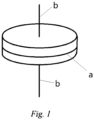
- a ring body of a steel ring mentioned in this application is an annular object. It has a certain width, and if the ring body of the present invention is unfolded, it will be a rectangular sheet-like object.
- the mentioned first axis a specifically refers to a central line on the ring body. If the ring body of the present invention is unfolded, the first axis a is a straight line arranged along the length of the rectangle, and the first axis a divides the rectangle into two parts with the same shape and area.
- the second axis b is a straight line perpendicular to the plane where the ring body is located.
- the ring body is an annular object, and the second axis b passes through the center of the circle where the ring body is located.
- the pipe fitting 1 is sleeved on the outer surface of the pipe 2, wherein the direction from the pipe 2 to the pipe fitting 1 is called the locking direction; and the direction from the pipe fitting 1 to the pipe 2 is called the detachment direction.
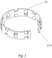
- FIGS. 2 to 3 show an embodiment of the present invention, which comprises a ring body 11. When this embodiment is not installed inside the pipe fitting, the ring body 11 is in an unclosed annular shape, that is, the first state. Therefore, the ring body 11 has a notch 113.
- FIG. 5 is a schematic particular structural view of locking teeth in this embodiment.
- the locking tooth comprises a fixed part fixedly connected to the inner surface of the ring body 11 and a contact part protruding from the inner surface of the ring body 11.
- the contact part is in contact with the pipe sleeved inside the pipe fitting during use, and can be embedded into the outer surface of the pipe when the pipe tends to be detached, thus playing a role of locking the pipe.
- the entire locking tooth is sheet-like, and the plane where the locking tooth is located forms a certain included angle with the inner surface of the ring body 11, and the included angle is less than 90 degrees.
- that included angles are the same. In other embodiments, different included angles may also be set according to specific needs. As shown in FIG.
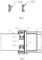
- a pair of locking teeth with two fixed parts arranged close to each other and two contact parts arranged separately constitute a first locking tooth group 111.
- Locking teeth with two fixed parts arranged separately and two contact parts arranged close to each other constitute a second locking tooth group 112.
- the two locking teeth included in the first locking tooth group 111 and the two locking teeth included in the second locking tooth group 112 are both arranged axisymmetrically with respect to the first axis a.
- the fixed parts of the two locking teeth included in the first locking tooth group 111 are arranged adjacent to each other, in other embodiments, the fixed parts of the two locking teeth can be arranged separately. As long as the distance between the fixed parts is smaller than the distance between the contact parts (that is, they are arranged in a back-to-back direction), and the fixed parts/the contact parts are axisymmetric with respect to the first axis a, a similar technical effect can also be achieved.
- first locking tooth group 111 or the second locking tooth group 112 there is at least one locking tooth, which is provided toward the locking direction, that is, its fixed part points to the detachment direction, and its contact part points to the locking direction.
- Both the first locking tooth group 111 and the second locking tooth group 112 in this embodiment include two locking teeth. In other embodiments, it is also possible to provide more than two locking teeth in a locking tooth group according to actual needs, as long as at least one locking tooth is provided toward the locking direction.
- FIG. 4 it is a schematic view of position setting of the first locking tooth group 111 and the second locking tooth group 112 in an embodiment of the present invention, and its three-dimensional schematic view is shown in FIG. 2 .
- the first locking tooth group 111 and the second locking tooth group 112 are respectively arranged centrosymmetrically with respect to the second axis b.
- the first locking tooth groups 111 and the second locking tooth groups 112 are spaced apart.
- the number of the first locking tooth groups 111 and the number of the second locking tooth groups 112 are not fixed, and the numbers can be adjusted according to the actual size and requirements of the ring body. In other numbers, it is possible that the first locking tooth groups 111 and the second locking tooth groups 112 are not spaced apart.
- FIG. 6 and FIG. 7 it is a schematic view of an embodiment of the present invention used for pipeline compression connection.
- the pipe fitting 1 is sleeved on the outer surface of the pipe 2, and a sealing ring 3 and a gasket 4 are respectively provided between the pipe 2 and the pipe fitting 1.
- the sealing performance of the pipeline interface is good, and there is no leakage of water or air.
- the pipe fitting 1 may be detached from the pipe 2 due to various reasons, so the ring body 11 of this embodiment is used.
- the ring body 11 Before the pipe fitting 1 is not compressed, the ring body 11 is sleeved on the pipe 2, and the gasket 4 and the sealing ring 3 are pressed tightly.
- the ring body 11 is in the first state, in an unclosed annular shape, and has a notch 113.
- the diameter of the pipe fitting 1 becomes smaller, the ring body 11 is in a closed annular shape under the restriction of the pipe fitting 1, and the notch 113 disappears.
- the ring body 11 is in the second state, and the locking teeth are embedded in the outer surface of the pipe 2.
- the pipe 2 When the pipe 2 has a tendency to detach from the pipe fitting 1, that is, the pipe 2 has a tendency to move in the detachment direction, the pipe 2 generates a friction force pointing to the detachment direction on the locking teeth.
- the contact part of the locking tooth provided toward the locking direction will be deformed after receiving the friction force pointing to the detachment direction, and its contact part will rotate around its fixed part, that is, the sheet-like locking tooth will be lifted upwards.
- This movement causes the height of the contact part of the locking tooth from the inner surface of the ring to further increase, thereby increasing the depth of the contact part embedded in the pipe 2, increasing the locking force of the ring on the pipe 2, and further locking the pipe 2 to prevent it from falling out of the pipe fitting 1.
Landscapes
- Engineering & Computer Science (AREA)
- General Engineering & Computer Science (AREA)
- Mechanical Engineering (AREA)
- Quick-Acting Or Multi-Walled Pipe Joints (AREA)
- Mutual Connection Of Rods And Tubes (AREA)
- Clamps And Clips (AREA)
Applications Claiming Priority (2)
| Application Number | Priority Date | Filing Date | Title |
|---|---|---|---|
| CN202010709387.3A CN113970019A (zh) | 2020-07-22 | 2020-07-22 | 一种钢圈 |
| PCT/CN2020/105064 WO2022016566A1 (zh) | 2020-07-22 | 2020-07-28 | 一种钢圈 |
Publications (4)
| Publication Number | Publication Date |
|---|---|
| EP4187136A1 true EP4187136A1 (de) | 2023-05-31 |
| EP4187136A4 EP4187136A4 (de) | 2024-06-26 |
| EP4187136B1 EP4187136B1 (de) | 2026-03-11 |
| EP4187136C0 EP4187136C0 (de) | 2026-03-11 |
Family
ID=79584740
Family Applications (1)
| Application Number | Title | Priority Date | Filing Date |
|---|---|---|---|
| EP20946482.5A Active EP4187136B1 (de) | 2020-07-22 | 2020-07-28 | Stahlring |
Country Status (5)
| Country | Link |
|---|---|
| US (1) | US11959573B2 (de) |
| EP (1) | EP4187136B1 (de) |
| CN (2) | CN113970019A (de) |
| AU (1) | AU2020460090B2 (de) |
| WO (1) | WO2022016566A1 (de) |
Families Citing this family (3)
| Publication number | Priority date | Publication date | Assignee | Title |
|---|---|---|---|---|
| CN108343792B (zh) * | 2018-03-02 | 2023-12-12 | 江苏浩峰汽车附件有限公司 | 一种管材连接件及其加工方法 |
| CN113970019A (zh) * | 2020-07-22 | 2022-01-25 | 浙江浩海管业有限公司 | 一种钢圈 |
| CN220379112U (zh) * | 2023-04-25 | 2024-01-23 | 宁波普锐流体科技有限公司 | 一种用于卡压连接结构的高抗拔性能的卡圈 |
Family Cites Families (19)
| Publication number | Priority date | Publication date | Assignee | Title |
|---|---|---|---|---|
| FR2292917A1 (fr) * | 1974-11-26 | 1976-06-25 | Everitube | Manchon de raccordement de tuyauteries |
| GB2182743B (en) * | 1985-10-30 | 1989-10-11 | Victaulic Plc | Improvements in or relating to pipe couplings and parts therefor |
| DE3710852C1 (de) * | 1987-04-01 | 1988-03-10 | Rasmussen Gmbh | Rohrkupplung |
| DE69424282T2 (de) * | 1994-09-14 | 2000-11-02 | John Derek Guest | Klemmring |
| DE29721760U1 (de) * | 1997-12-10 | 1998-01-29 | Franz Viegener II GmbH & Co. KG, 57439 Attendorn | Unlösbare Preßverbindung zwischen einem Fitting und einem Metallrohrende |
| US6499771B1 (en) * | 2000-07-18 | 2002-12-31 | Victaulic Company Of America | Mechanical pipe coupling with toothed retainer |
| JP4489317B2 (ja) * | 2001-03-29 | 2010-06-23 | 有限会社ユース北浦 | 抜け止めリングおよび雄ねじ体接続構造 |
| DE10335513B4 (de) * | 2003-03-24 | 2010-05-12 | Simag, Blazenka | Rohrverbindung |
| DE102009007303B4 (de) * | 2009-02-03 | 2023-05-04 | Viega Technology Gmbh & Co. Kg | Fitting für dickwandige Rohre |
| KR101207634B1 (ko) * | 2012-08-24 | 2012-12-03 | 강석근 | 압력관 연결용 이음관의 원터치 3단 체결장치 및 이를 이용한 압력관의 시공방법 |
| KR101468508B1 (ko) * | 2013-08-29 | 2014-12-04 | 정우금속공업 주식회사 | 파이프 연결구 |
| NL2015413B1 (en) * | 2015-09-08 | 2017-03-22 | Vsh Fittings B V | Press fitting for pipes having a check ring. |
| KR101954307B1 (ko) * | 2016-07-27 | 2019-05-17 | 정우금속공업 주식회사 | 파이프 연결장치 |
| US11015748B2 (en) * | 2017-03-31 | 2021-05-25 | A.Y. Mcdonald Mfg. Co. | Compression pipe fitting with wide range grip rings |
| US11088515B2 (en) * | 2017-08-31 | 2021-08-10 | Eaton Intelligent Power Limited | Press fitting for electrical conduit |
| US11451027B2 (en) * | 2018-06-08 | 2022-09-20 | Eaton Intelligent Power Limited | Press coupler for electrical conduit |
| AU2018444718B2 (en) * | 2018-10-09 | 2025-05-08 | Zhuji City Howhi Air Conditioners Made Co., Ltd. | Anti-off steel ring and fixed sealing device for snap-fit pipe fitting |
| CN213452214U (zh) * | 2020-07-22 | 2021-06-15 | 诸暨市浩海空调器制造有限公司 | 一种钢圈 |
| CN113970019A (zh) * | 2020-07-22 | 2022-01-25 | 浙江浩海管业有限公司 | 一种钢圈 |
-
2020
- 2020-07-22 CN CN202010709387.3A patent/CN113970019A/zh active Pending
- 2020-07-28 WO PCT/CN2020/105064 patent/WO2022016566A1/zh not_active Ceased
- 2020-07-28 AU AU2020460090A patent/AU2020460090B2/en active Active
- 2020-07-28 CN CN202080102631.8A patent/CN115803552B/zh active Active
- 2020-07-28 EP EP20946482.5A patent/EP4187136B1/de active Active
-
2022
- 2022-06-27 US US17/850,627 patent/US11959573B2/en active Active
Also Published As
| Publication number | Publication date |
|---|---|
| CN115803552B (zh) | 2025-05-30 |
| EP4187136B1 (de) | 2026-03-11 |
| EP4187136A4 (de) | 2024-06-26 |
| WO2022016566A1 (zh) | 2022-01-27 |
| CN115803552A (zh) | 2023-03-14 |
| US20220325835A1 (en) | 2022-10-13 |
| AU2020460090A1 (en) | 2023-03-23 |
| CA3186810A1 (en) | 2022-01-27 |
| EP4187136C0 (de) | 2026-03-11 |
| AU2020460090B2 (en) | 2026-04-02 |
| CN113970019A (zh) | 2022-01-25 |
| US11959573B2 (en) | 2024-04-16 |
Similar Documents
| Publication | Publication Date | Title |
|---|---|---|
| US11959573B2 (en) | Steel ring | |
| CN104121434B (zh) | 防止管件与管接头松脱的管接头 | |
| US2937893A (en) | Resealable conduit coupling with abutting resilient flange surfaces | |
| US3485516A (en) | Double-pipe line flange connection | |
| US3433509A (en) | Pipe coupling | |
| US2413308A (en) | Joint | |
| US1951034A (en) | Adjustable repair clamp for bell and spigot joints | |
| CN204533919U (zh) | 一种波纹管自密封式机械压紧套筒 | |
| US3458220A (en) | Fluid couplings | |
| GB1148556A (en) | Improvements in or relating to flanged pipe connections | |
| CA3186810C (en) | Steel ring | |
| CN213452214U (zh) | 一种钢圈 | |
| CN204717181U (zh) | 改进型三角环密封垫圈和改进型三角环密封活接及法兰 | |
| US3635503A (en) | Band clamp with service outlet | |
| CN205716117U (zh) | 一种双密封管接头 | |
| JP5719529B2 (ja) | ユニオン継手およびユニオン継手のシール構造 | |
| JPH10176823A (ja) | 高温配管フランジ用シール部材 | |
| US3596932A (en) | Quick couple union | |
| CN115823087A (zh) | 一种锁线螺母组件及其使用方法 | |
| KR20190091172A (ko) | 파이프 배관용 2단 플랜지 | |
| CN112856059A (zh) | 一种管接头 | |
| CN215928710U (zh) | 一种金属直通接头 | |
| CN215445434U (zh) | 一种用于管道与三通连接的快速连接结构 | |
| CN205716124U (zh) | 一种金属管与非金属管的连接装置 | |
| JP7514431B2 (ja) | ハウジング形管継手およびこれを用いた管継手方法 |
Legal Events
| Date | Code | Title | Description |
|---|---|---|---|
| STAA | Information on the status of an ep patent application or granted ep patent |
Free format text: STATUS: THE INTERNATIONAL PUBLICATION HAS BEEN MADE |
|
| PUAI | Public reference made under article 153(3) epc to a published international application that has entered the european phase |
Free format text: ORIGINAL CODE: 0009012 |
|
| STAA | Information on the status of an ep patent application or granted ep patent |
Free format text: STATUS: REQUEST FOR EXAMINATION WAS MADE |
|
| 17P | Request for examination filed |
Effective date: 20230222 |
|
| AK | Designated contracting states |
Kind code of ref document: A1 Designated state(s): AL AT BE BG CH CY CZ DE DK EE ES FI FR GB GR HR HU IE IS IT LI LT LU LV MC MK MT NL NO PL PT RO RS SE SI SK SM TR |
|
| DAV | Request for validation of the european patent (deleted) | ||
| DAX | Request for extension of the european patent (deleted) | ||
| A4 | Supplementary search report drawn up and despatched |
Effective date: 20240527 |
|
| RIC1 | Information provided on ipc code assigned before grant |
Ipc: F16L 13/14 20060101ALI20240521BHEP Ipc: F16L 37/091 20060101AFI20240521BHEP |
|
| GRAP | Despatch of communication of intention to grant a patent |
Free format text: ORIGINAL CODE: EPIDOSNIGR1 |
|
| STAA | Information on the status of an ep patent application or granted ep patent |
Free format text: STATUS: GRANT OF PATENT IS INTENDED |
|
| INTG | Intention to grant announced |
Effective date: 20251218 |
|
| GRAS | Grant fee paid |
Free format text: ORIGINAL CODE: EPIDOSNIGR3 |
|
| GRAA | (expected) grant |
Free format text: ORIGINAL CODE: 0009210 |
|
| STAA | Information on the status of an ep patent application or granted ep patent |
Free format text: STATUS: THE PATENT HAS BEEN GRANTED |
|
| AK | Designated contracting states |
Kind code of ref document: B1 Designated state(s): AL AT BE BG CH CY CZ DE DK EE ES FI FR GB GR HR HU IE IS IT LI LT LU LV MC MK MT NL NO PL PT RO RS SE SI SK SM TR |
|
| REG | Reference to a national code |
Ref country code: CH Ref legal event code: F10 Free format text: ST27 STATUS EVENT CODE: U-0-0-F10-F00 (AS PROVIDED BY THE NATIONAL OFFICE) Effective date: 20260311 Ref country code: GB Ref legal event code: FG4D |
|
| REG | Reference to a national code |
Ref country code: DE Ref legal event code: R096 Ref document number: 602020068644 Country of ref document: DE |
|
| REG | Reference to a national code |
Ref country code: IE Ref legal event code: FG4D |
|
| U01 | Request for unitary effect filed |
Effective date: 20260330 |
|
| U07 | Unitary effect registered |
Designated state(s): AT BE BG DE DK EE FI FR IT LT LU LV MT NL PT RO SE SI Effective date: 20260407 |