US11088515B2 - Press fitting for electrical conduit - Google Patents
Press fitting for electrical conduit Download PDFInfo
- Publication number
- US11088515B2 US11088515B2 US15/692,850 US201715692850A US11088515B2 US 11088515 B2 US11088515 B2 US 11088515B2 US 201715692850 A US201715692850 A US 201715692850A US 11088515 B2 US11088515 B2 US 11088515B2
- Authority
- US
- United States
- Prior art keywords
- press
- conduit
- fitting
- piece
- fitting body
- Prior art date
- Legal status (The legal status is an assumption and is not a legal conclusion. Google has not performed a legal analysis and makes no representation as to the accuracy of the status listed.)
- Active, expires
Links
- 238000000034 method Methods 0.000 claims abstract description 20
- 230000008569 process Effects 0.000 claims abstract description 19
- 230000007704 transition Effects 0.000 claims description 10
- 238000003780 insertion Methods 0.000 claims description 3
- 230000037431 insertion Effects 0.000 claims description 3
- 239000013256 coordination polymer Substances 0.000 description 9
- 239000000463 material Substances 0.000 description 6
- 229910052751 metal Inorganic materials 0.000 description 6
- 239000002184 metal Substances 0.000 description 6
- 230000008878 coupling Effects 0.000 description 4
- 238000010168 coupling process Methods 0.000 description 4
- 238000005859 coupling reaction Methods 0.000 description 4
- 229910000831 Steel Inorganic materials 0.000 description 2
- 229910052782 aluminium Inorganic materials 0.000 description 2
- XAGFODPZIPBFFR-UHFFFAOYSA-N aluminium Chemical compound [Al] XAGFODPZIPBFFR-UHFFFAOYSA-N 0.000 description 2
- 239000007788 liquid Substances 0.000 description 2
- 238000004080 punching Methods 0.000 description 2
- 239000010959 steel Substances 0.000 description 2
- 239000000853 adhesive Substances 0.000 description 1
- 230000001070 adhesive effect Effects 0.000 description 1
- 238000010276 construction Methods 0.000 description 1
- 230000007423 decrease Effects 0.000 description 1
- 230000003247 decreasing effect Effects 0.000 description 1
- 238000009429 electrical wiring Methods 0.000 description 1
- 238000012986 modification Methods 0.000 description 1
- 230000004048 modification Effects 0.000 description 1
- 229920000642 polymer Polymers 0.000 description 1
- 230000000717 retained effect Effects 0.000 description 1
Images


Classifications
-
- H—ELECTRICITY
- H02—GENERATION; CONVERSION OR DISTRIBUTION OF ELECTRIC POWER
- H02G—INSTALLATION OF ELECTRIC CABLES OR LINES, OR OF COMBINED OPTICAL AND ELECTRIC CABLES OR LINES
- H02G3/00—Installations of electric cables or lines or protective tubing therefor in or on buildings, equivalent structures or vehicles
- H02G3/02—Details
- H02G3/06—Joints for connecting lengths of protective tubing or channels, to each other or to casings, e.g. to distribution boxes; Ensuring electrical continuity in the joint
- H02G3/0616—Joints for connecting tubing to casing
- H02G3/0625—Joints for connecting tubing to casing with means for preventing disengagement of conductors
- H02G3/065—Joints for connecting tubing to casing with means for preventing disengagement of conductors with means biting into the conductor-insulation, e.g. teeth-like elements or gripping fingers
-
- F—MECHANICAL ENGINEERING; LIGHTING; HEATING; WEAPONS; BLASTING
- F16—ENGINEERING ELEMENTS AND UNITS; GENERAL MEASURES FOR PRODUCING AND MAINTAINING EFFECTIVE FUNCTIONING OF MACHINES OR INSTALLATIONS; THERMAL INSULATION IN GENERAL
- F16L—PIPES; JOINTS OR FITTINGS FOR PIPES; SUPPORTS FOR PIPES, CABLES OR PROTECTIVE TUBING; MEANS FOR THERMAL INSULATION IN GENERAL
- F16L13/00—Non-disconnectable pipe joints, e.g. soldered, adhesive, or caulked joints
- F16L13/14—Non-disconnectable pipe joints, e.g. soldered, adhesive, or caulked joints made by plastically deforming the material of the pipe, e.g. by flanging, rolling
- F16L13/141—Non-disconnectable pipe joints, e.g. soldered, adhesive, or caulked joints made by plastically deforming the material of the pipe, e.g. by flanging, rolling by crimping or rolling from the outside
- F16L13/142—Non-disconnectable pipe joints, e.g. soldered, adhesive, or caulked joints made by plastically deforming the material of the pipe, e.g. by flanging, rolling by crimping or rolling from the outside with a sealing element inserted into the female part before crimping or rolling
-
- F—MECHANICAL ENGINEERING; LIGHTING; HEATING; WEAPONS; BLASTING
- F16—ENGINEERING ELEMENTS AND UNITS; GENERAL MEASURES FOR PRODUCING AND MAINTAINING EFFECTIVE FUNCTIONING OF MACHINES OR INSTALLATIONS; THERMAL INSULATION IN GENERAL
- F16L—PIPES; JOINTS OR FITTINGS FOR PIPES; SUPPORTS FOR PIPES, CABLES OR PROTECTIVE TUBING; MEANS FOR THERMAL INSULATION IN GENERAL
- F16L37/00—Couplings of the quick-acting type
- F16L37/08—Couplings of the quick-acting type in which the connection between abutting or axially overlapping ends is maintained by locking members
- F16L37/084—Couplings of the quick-acting type in which the connection between abutting or axially overlapping ends is maintained by locking members combined with automatic locking
- F16L37/091—Couplings of the quick-acting type in which the connection between abutting or axially overlapping ends is maintained by locking members combined with automatic locking by means of a ring provided with teeth or fingers
-
- H—ELECTRICITY
- H02—GENERATION; CONVERSION OR DISTRIBUTION OF ELECTRIC POWER
- H02G—INSTALLATION OF ELECTRIC CABLES OR LINES, OR OF COMBINED OPTICAL AND ELECTRIC CABLES OR LINES
- H02G1/00—Methods or apparatus specially adapted for installing, maintaining, repairing or dismantling electric cables or lines
- H02G1/06—Methods or apparatus specially adapted for installing, maintaining, repairing or dismantling electric cables or lines for laying cables, e.g. laying apparatus on vehicle
- H02G1/08—Methods or apparatus specially adapted for installing, maintaining, repairing or dismantling electric cables or lines for laying cables, e.g. laying apparatus on vehicle through tubing or conduit, e.g. rod or draw wire for pushing or pulling
-
- H—ELECTRICITY
- H02—GENERATION; CONVERSION OR DISTRIBUTION OF ELECTRIC POWER
- H02G—INSTALLATION OF ELECTRIC CABLES OR LINES, OR OF COMBINED OPTICAL AND ELECTRIC CABLES OR LINES
- H02G3/00—Installations of electric cables or lines or protective tubing therefor in or on buildings, equivalent structures or vehicles
- H02G3/22—Installations of cables or lines through walls, floors or ceilings, e.g. into buildings
Definitions
- the present disclosure generally relates to a press fitting for an electrical conduit.
- Electrical conduits are tubes used to protect and route electrical wiring in a building or other structure. Fittings for electrical conduits including, but are not limited to: box connecters used to connect conduit to a junction or other electrical box; couplings, used to connect pieces of electrical conduit to one another when installing a run of conduit; and conduit bodies (e.g., Condulets®) used to connect pieces of electrical conduit to one another to provide pulling access in a run of conduit, to allow more bends to be made in a particular section of conduit, to conserve space where a full size bend radius would be impractical or impossible, and/or to split a conduit run into multiple directions.
- box connecters used to connect conduit to a junction or other electrical box
- couplings used to connect pieces of electrical conduit to one another when installing a run of conduit
- conduit bodies e.g., Condulets®
- a press fitting for an electrical conduit generally comprises a fitting body having first and second open ends, and an interior surface defining a passage adapted to receive a piece of the electrical conduit therein.
- the fitting body includes a press-connection section that is deformable radially inward during a press connection process.
- a press connector is in the passage at the press-connection section of the fitting body.
- the press connector includes teeth adapted to engage the piece of electrical conduit received in the passage when the press-connection section is deformed radially inward during the press connection process.
- a conduit retainer is in the passage of the fitting body. The conduit retainer is configured to releasably grip and removably retain the piece of electrical conduit in the fitting body before the press-connection section is deformed radially inward during the press connection process.
- a press fitting for an electrical conduit generally comprises a fitting body having first and second open ends.
- the fitting body includes a press-connection section that is deformable radially inward during a press connection process.
- a press connector is in the press-connection section of the fitting body.
- the press connector includes teeth adapted to engage the piece of electrical conduit received in the fitting body when the press-connection section is deformed radially inward during the press connection process.
- a socket in the fitting body apart from the press-connection section is adapted to receive a piece of electrical conduit therein. At least a section of the socket has a cross-sectional diameter that tapers in a direction away from the press-connection section.
- FIG. 1 is a perspective of one embodiment of an electrical conduit fitting constructed according to the teachings of the present disclosure
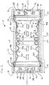
- FIG. 2 is a cross section of the fitting
- FIG. 3 is an enlarged side elevational view of a press connector of the fitting
- FIG. 4 is an enlarged front elevational view of a conduit retainer of the fitting
- FIG. 5 is a section of the conduit retainer taken in the plane defined by the line 5 - 5 in FIG. 4 ;
- FIG. 6 is similar to FIG. 2 , but showing two pieces of straight, non-threaded conduit received in the fitting;
- FIG. 7 is similar to FIG. 2 , but showing two pieces of NPT threaded conduit received in the fitting;
- FIG. 8 is a perspective of another embodiment of a conduit retainer
- FIG. 9 is a cross section of another embodiment of an electrical conduit fitting constructed according to the teachings of the present disclosure.
- FIG. 10 is similar to FIG. 9 , but showing two pieces of straight, non-threaded conduit received in the fitting;
- FIG. 11 is a cross section of yet another embodiment of an electrical conduit fitting constructed according to the teachings of the present disclosure.
- FIG. 12 is similar to FIG. 11 , but showing two pieces of straight, non-threaded conduit received in the fitting;
- FIG. 13 is a cross section of yet another embodiment of an electrical conduit fitting constructed according to the teachings of the present disclosure.
- FIG. 14 is similar to FIG. 13 , but showing two pieces of straight, non-threaded conduit received in the fitting;
- FIG. 15 is similar to FIG. 13 , but showing two pieces of NPT threaded conduit received in the fitting.
- the present disclosure relates to an electrical conduit press fitting—such as but not limited to, a box connector, a coupling, and a conduit body—designed and constructed to be coupled to at least one piece of electrical conduit by a press connection.
- the press fitting includes at least one of, but not necessarily each of: a conduit retainer for retaining a piece of conduit in the press fitting before press connection; and an alignment structure for axially aligning a piece of conduit in the press fitting before press connection.
- the conduit retainer is designed and constructed to include the alignment structure to also perform the alignment function.
- the alignment structure is separate from the conduit retainer.
- an electrical conduit fitting constructed according to the teachings of the present disclosure is generally indicated at reference numeral 10 .
- this electrical conduit fitting 10 is in the form of a coupling designed and constructed to connect pieces of electrical conduit to one another when installing a run of conduit.
- the electrical conduit fitting may be of other types, including but not limited to a box connector and a conduit body, with the teachings set forth herein with respect to the illustrated coupling applying equally to other types of conduit fittings that connect to a piece of electrical conduit by press connection.
- the electrical conduit fitting 10 includes a generally cylindrical fitting body 12 having opposing first and second open ends 14 , 16 , and an interior surface 18 defining an internal passage extending axially along a longitudinal axis LA of the fitting body between the first and second open ends thereof.
- a central transverse plane CP intersects the longitudinal axis LA at a generally orthogonal angle at a mid-length of the body 12 .
- the fitting body 12 includes first and second press-connection sections 20 , 22 , respectively, adjacent the respective first and second open ends 14 , 16 , and a central portion 24 disposed between and interconnecting the first and second press-connection sections 20 , 22 .
- the press-connection sections 20 , 22 have maximum inner and outer diameters that are greater than respective inner and outer diameters of the central portion 24 .
- the press-connection sections 20 , 22 have respective transition portions that step down to the decreased inner and outer diameters of the central section 24 .
- the press-connection sections 20 , 22 are deformable radially inward to press fit the fitting 10 on the piece of electrical conduit.
- the fitting body 12 may be formed from metal, such as aluminum, steel, or other metal.
- the fitting body 12 may be formed from other materials.
- a press connector 28 , a separator 30 , and a gasket 32 are received in each of the first and second press-connection sections 20 , 22 of the fitting body 12 .
- the first and second open ends 14 , 16 may include crimped or bent portions to 33 to retain the press connector 28 , the separator 30 , and the gasket 32 in each of the first and second press-connection sections 20 , 22 , although the components may be retained in the fitting body 12 in other ways.
- Each of the press connector 28 , the separator 30 , and the gasket 32 are generally ring-shaped (e.g., have annular shapes) defining axial openings that are generally axially aligned and generally axially aligned with the longitudinal axis of the fitting body 12 .
- the corresponding press connector 28 , separator 30 , and gasket 32 are adjacent to one another, with the press connector being axially outward of the gasket relative to the central transverse plane CP and the separator 30 disposed axially between the press connector and the gasket.
- the press-connectors 28 may have an open or discontinuous ring shape.
- the separator 30 and the gasket 32 may also have this open or discontinuous ring shape.
- Each press connector 28 includes a deformable annular body and barbs or teeth 36 (e.g., pairs or sets of barbs) extending radially inward and spaced apart from one another around the radially deformable body.
- the teeth 36 are configured to engage and dig into a piece of conduit inserted into the fitting 10 during a press connection process in which the annular connection body is radially deformed (e.g., radially compressed) to connect the fitting to the piece of conduit.
- the press connectors 28 may be formed from metal and the teeth may be formed by punching operation or in other ways.
- Each gasket 32 makes a desired and suitable gas and/or liquid tight seal with the piece of conduit inserted into the fitting 10 during the press connection process.
- Each gasket 32 may be formed from a suitable polymer, such as rubber, or other material for making a desired and suitable gas and/or liquid tight seal with the piece of conduit inserted into the fitting during the press connection process.
- Each separator 30 separates the corresponding gasket 32 and press connector 28 so that the press connector does not impinge on the gasket during the press connection process.
- the separator 30 may include an outer surface generally corresponding with an adjacent surface of the gasket 32 .
- the separator 30 may be formed from metal or other material. It is understood that in one or more embodiments, the fitting 10 may not include one or more of the gasket 32 and the separator 30 .
- the press-connectors 28 may be of other configurations for connection to the pieces of electrical conduit.
- the electrical conduit fitting 10 further includes two conduit retainers, each generally indicated at reference numeral 40 , received in the passage of the fitting body 12 (e.g., received in the central portion 24 ).
- each conduit retainer 40 is configured to grip (e.g., releasably grip) and retain (e.g., removably retain) a piece of electrical conduit inserted in the fitting 10 .
- the conduit retainer 40 is also configured to axially align the piece of electrical conduit within the fitting 10 .
- the fitting may include one conduit retainer 40 or more than two conduit retainers, depending on the type of fitting and its application.
- the two conduit retainers 40 may be combined into a single, one-piece component or otherwise connected to one another.
- each conduit retainer 40 includes a generally cylindrical or annular conduit retainer body 42 having first and second open longitudinal ends 44 , 46 , respectively, and an internal socket 48 , extending axially along an axis A of the conduit retainer body between the first and second open longitudinal ends.
- Each conduit retainer 40 may have an open cylindrical or annular shape, as shown in FIG. 5 , for example.
- the conduit retainers 40 are received in the central portion 24 of the fitting body 12 and are generally arranged in the fitting body 12 as mirror images about the central transverse plane CP, as shown in FIG. 2 .
- each conduit retainer 40 has a flared diameter (e.g., flared inner and outer diameter) sized and shaped to engage an internal shoulder of the fitting body 12 intermediate the respective one of the first and second press-connection sections 20 , 22 and the central portion 24 .
- Each conduit retainer 40 may be received in the fitting body 12 as a close clearance fit and captured between the other retainer and the corresponding gaskets 32 or may be received as a press or interference fit.
- the axis A of the conduit retainer 40 is generally aligned (i.e., coaxial) with the longitudinal axis LA of the fitting body 12 .
- the conduit retainers 40 may be attached to the fitting body 12 , such as by adhesive or a mechanical fastener.
- an internal conduit stop 50 at the second open longitudinal end is defined by an inner, annular curl.
- the conduit retainers 40 may be formed from metal, such as aluminum or steel, or plastic, or other material.
- At least one detent extends radially inward from the conduit retainer body 42 and toward the axis of the body.
- the conduit retainer 40 includes sets (e.g., pairs) of the detents 52 a , 52 b , where the sets are spaced apart from one another around the conduit retainer body 40 .
- Each set includes one of the first detents 52 a and one of the second detents 52 b .
- the detents 52 a , 52 b are deflectable (e.g., resiliently deflectable or deformable) in a radially outward direction relative to the axis A of the conduit retainer body 42 .
- the first detents 52 a have radial dimensions relative to the axis A that are less than the radial dimensions of the second detents 52 b .
- the first detents 52 a are generally aligned circumferentially and define a first effective inner diameter d 1 of the conduit retainer 40
- the second detents 52 b are generally aligned circumferentially and define a second effective inner diameter d 2 of the conduit retainer that is less than the first effective inner diameter.
- the first detents 52 a are generally adjacent the first longitudinal end 46 and the second detents 52 b are more adjacent the second longitudinal end 48 so that the effective inner diameter of the conduit retainer 40 tapers or decreases toward the second longitudinal end.
- this taper is a generally straight taper as shown in cross section; it is understood that in other embodiments the taper may be curviliner or other shapes in cross section. It is understood that in other embodiments, the one or more detents may define a uniform effective inner diameter that does not taper.
- the illustrated detents 52 a , 52 b are integrally formed with the conduit retainer body 42 , although the detents may be formed separate and attached to the conduit retainer body.
- the detents 52 a , 52 b may be formed by a punching operation.
- the detents 52 a , 52 b may be of other configurations, such as flaps, or barbs, or tabs, or nubs, or springs, or other structures capable of releasably gripping a piece of electrical conduit inserted into the fitting 10 .
- the detents are 52 a , 52 b are configured to apply a gripping force on a piece of electrical conduit (e.g., both a non-threaded and a threaded electrical conduit) inserted into the fitting 10 and to axially align or center the piece of the electrical conduit in the fitting.
- a piece of electrical conduit e.g., both a non-threaded and a threaded electrical conduit
- the piece of electrical conduit EC S , EC T engages the detents 52 a , 52 b , causing the detents to resilient deflect (e.g., flatten). This resilient deflection imparts a spring-like gripping force on the piece of electrical conduit EC S , EC T in the radial direction to hold the piece of electrical conduit in position in the fitting 10 .
- This gripping force may be overcome by applying sufficient withdrawal force on the piece of electrical conduit EC S , EC T to remove the piece of electrical conduit from the fitting 10 if desired by the user.
- the detents 52 a , 52 b center or axially align the piece of electrical conduit EC S , EC T in the fitting 10 (e.g., axis LA of fitting 10 is coaxial or parallel to axis P of conduit).
- the illustrated detents 52 a , 52 b allow the fitting 10 to be used with either the electrical conduit EC S having an longitudinal end portion with a constant diameter (e.g., a non-threaded conduit) or the electrical conduit EC T having a tapering longitudinal end portion (e.g., an NPT threaded conduit). This is due to the taper of the effective inner diameter defined by the different detents 52 a , 52 b .
- the detents 52 a , 52 b may not define a taper but may define a uniform effective inner diameter that does not taper.
- the conduit retainer 40 retains and centers the piece of electrical conduit EC S , EC T to aid the user in forming the conduit run, including checking lengths and arrangement of the run, before forming the permanent press connection.
- the stop 50 in the conduit retainer 40 also facilitates positioning the piece of electrical conduit EC S , EC T within the fitting 10 so that the user knows depth at which the piece of conduit is inserted into the fitting (which also indicates the distance apart the two pieces of electrical conduit are in the fitting). This maximum depth of insertion and/or distance between the ends of the two pieces of electrical conduit EC S , EC T can be communicated to the user on the fitting body 12 or elsewhere.
- the fitting 10 is press connected to the piece of electrical conduit EC S , EC T using a press tool including jaws that radially press and mechanically deform the press connection sections 14 , 16 of the fitting body 12 in a radially inward direction such that the teeth 36 of the press connector 28 engage and dig into the piece of electrical conduit.
- conduit retainer 140 another embodiment of a conduit retainer, similar to the conduit retainer 40 , is indicated at reference numeral 140 .
- this conduit retainer 140 has the same components and functions as the first conduit retainer 40 , and therefore, unless explicitly stated, the teachings set forth above with respect to the first conduit retainer apply equally to this conduit retainer.
- the conduit retainer body 142 of the present conduit retainer 140 includes longitudinal struts 141 extending between an interconnecting the first and second open longitudinal ends 44 , 46 .
- the struts 141 are spaced apart from one another around the axis A 1 to define slot-shaped openings 143 between the struts.
- Each strut 141 has one of the sets (e.g., pairs) of the first and second detents 152 a , 152 b .
- Each strut 141 and/or each detent 152 a , 152 b is resiliently deflectable radially outward when the piece of electrical conduit EC S , EC T is inserted into the conduit retainer 140 to imparts a spring-like gripping force on the piece of electrical conduit in the radial direction to hold the piece of electrical conduit in position in the fitting 10 , like the first conduit retainer 40 .
- the conduit retainer 140 may be received in the fitting body 12 in the same way as the conduit retainer 40 .
- FIGS. 9 and 10 another embodiment of an electrical conduit fitting is generally indicated at reference numeral 210 .
- this fitting 210 includes identical component as described above with respect to the first fitting 10 . Accordingly, like component are indicated by corresponding reference numerals.
- the present fitting 210 includes at least one conduit retainer 240 (e.g., two conduit retainers) configured to grip and retain (e.g., removably retain) a piece of electrical conduit inserted into the fitting 10 .
- Each of the illustrated conduit retainers 240 has a generally annular or ring cross-sectional shape (e.g., an open ring shape) defining a socket 245 for receiving piece of electrical conduit.
- the opening 245 is generally axially aligned with the openings defined by the gasket 32 , the separator 30 , and the press connector 28 , respectively.
- a minimum diameter d 4 of the opening 245 is less than diameters of the openings defined by the gasket 32 , the separator 30 , and the press connector 28 , respectively.
- Each conduit retainer 240 is resilient and deflectable to impart a spring-like, releasable gripping force on the piece of electrical conduit in the radial direction to hold the piece of electrical conduit in position in the fitting 210 , like the first conduit retainer 40 .
- the conduit retainers 240 may be formed from metal or plastic or other material.
- the conduit retainers 240 may be captured between the fitting body 12 and the gasket 32 or may be coupled or otherwise fastened in the fitting body in other ways.
- one or more separators 30 may include the conduit retainer.
- the conduit retainer may be an integral component or structure of the separator 30 or may be otherwise connected to the separator.
- FIGS. 11 and 12 another embodiment of an electrical conduit fitting is generally indicated at reference numeral 310 .
- this fitting 310 includes identical components as described above with respect to the first fitting 10 . Accordingly, like components are indicated by corresponding reference numerals.
- the present fitting 310 includes gaskets 332 that also function as conduit retainers configured to grip and retain (e.g., removably retain) a piece of electrical conduit inserted into the fitting 10 in addition to its function as a gasket as set forth above with respect to the gasket 32 .
- Each gasket 332 defines an opening 345 having a reduced minimum diameter d 5 that is less than the gasket 32 .
- Each conduit retainer 332 is resilient and deflectable to impart a spring-like, releasable gripping force on the piece of electrical conduit in the radial direction to hold the piece of electrical conduit in position in the fitting 310 , like the first conduit retainer 40 .
- the gasket 240 may be formed from plastic or other material.
- FIGS. 13-15 another embodiment of an electrical conduit fitting is generally indicated at reference numeral 410 .
- this fitting 410 includes identical components as described above with respect to the fitting 210 described in reference to FIGS. 9 and 10 . Accordingly, like components are indicated by corresponding reference numerals.
- FIG. 13 illustrates the fitting 410 as including the conduit retainer 210 , with the understanding that the conduit retainer 240 may be omitted without necessarily departing from the scope of the present invention, as shown in FIGS. 14 and 15 .
- a different type of conduit retainer such as a conduit retainer constructed according to the teachings of the conduit retainer 40 , may be utilized.
- the present fitting 10 includes a fitting body 412 having a central portion 424 with a non-uniform inner cross-sectional dimension (e.g., a non-uniform inner diameter) defining an internal socket 448 .
- the outer cross-sectional dimension e.g., the outer diameter
- the outer cross-sectional dimension is also non-uniform, although it may be uniform in some embodiments.
- the interior surface 418 of the central portion 424 of the fitting body 412 includes: opposite first and second axially outer sections, 460 , 462 adjacent the respective first and second press-connection portions 20 , 22 ; first and second axially inner sections 464 , 466 , juxtaposed to one another and between the first and second axially outer sections; a first transition portion 468 disposed between and interconnecting the first axially outer section 460 and the first axially inner section 464 ; and a second transition portion 470 disposed between and interconnecting the second axially outer section 462 and the first axially inner section 466 .
- the terms “axially inner” and “axially outer” are relative terms in reference to the center transverse plane CP.
- the illustrated embodiment shows the fitting body 412 as being formed as an integral, one-piece component.
- the axially outer sections 460 , 462 each define generally uniform inner diameter of the fitting body 412 is greater than an outer maximum diameter of either one of the electrical conduit EC S having an longitudinal end portion with a constant diameter (e.g., a non-threaded conduit) or the electrical conduit EC T having a tapering longitudinal end portion (e.g., an NPT threaded conduit). Accordingly, as shown in FIGS. 14 and 15 , the pieces of electrical conduit EC S , EC T are insertable into the portions of the fitting body 412 defined by the axially outer sections 460 , 462 .
- the axially outer sections 460 , 462 may facilitate centering of the electrical conduit EC S .
- the transition portions 468 , 470 abruptly extend radially inward toward the longitudinal axis LA to define shoulders (or stops) such that the transitions portions define an inner diameter of the fitting body 412 that is less than the inner diameter at the axially outer sections 460 , 462 .
- the minimum inner diameters of the fitting body at the transition portions are less than the outer diameter of the electrical conduit EC S having an longitudinal end portion with a constant diameter such that the piece of electrical conduit EC S engages the transition portion 468 , 470 and is inhibited from further insertion toward the central transverse plane CP.
- the locations of the stops may be at a predetermined distance from the central transverse plane CP, which is communicated to the user, so that the user is aware of the spacing between the two pieces of electrical conduit when the two pieces are received in the fitting body 412 .
- the axially inner sections 464 , 466 taper inward toward the longitudinal axis LA from the respective transition portions 468 , 470 to the central transverse plane CP.
- the taper of the axially inner sections 464 , 466 generally corresponds to the taper of the end of the NPT threaded conduit such that the axially inner sections center the NPT threaded conduit in the fitting body 412 .
- the taper of the axially inner sections 464 , 466 may also inhibit the NPT threaded conduit from being inserted past the central transverse plane CP.
- the interior surface 418 adjacent the junction of the axially inner sections 464 , 466 may be rounded or smoothed to inhibit damaging electrical wires passing over the interior surface.
- an insert of the fitting body 412 may be used to define the socket 448 having a non-uniform (e.g., tapering) cross section.
- inner diameter of the wall of the fitting body may be uniform and an insert having a non-uniform, tapering inner diameter defining the socket 448 may be inserted into the passage defined by the wall of the fitting body.
- Each embodiment of the electrical conduits described herein may be designed and configured to meet the standards set forth in UL 514B.
Landscapes
- Engineering & Computer Science (AREA)
- General Engineering & Computer Science (AREA)
- Architecture (AREA)
- Civil Engineering (AREA)
- Structural Engineering (AREA)
- Mechanical Engineering (AREA)
- Quick-Acting Or Multi-Walled Pipe Joints (AREA)
- Flanged Joints, Insulating Joints, And Other Joints (AREA)
- Details Of Connecting Devices For Male And Female Coupling (AREA)
Abstract
Description
Claims (20)
Priority Applications (6)
| Application Number | Priority Date | Filing Date | Title |
|---|---|---|---|
| US15/692,850 US11088515B2 (en) | 2017-08-31 | 2017-08-31 | Press fitting for electrical conduit |
| CA3015832A CA3015832A1 (en) | 2017-08-31 | 2018-08-29 | Press fitting for electrical conduit |
| MX2018010471A MX388099B (en) | 2017-08-31 | 2018-08-30 | ELECTRICAL CONDUIT PRESS ADJUSTMENT. |
| US17/383,207 US11652339B2 (en) | 2017-08-31 | 2021-07-22 | Press fitting for electrical conduit |
| US18/298,195 US12224563B2 (en) | 2017-08-31 | 2023-04-10 | Press fitting for electrical conduit |
| US19/007,110 US20250337227A1 (en) | 2017-08-31 | 2024-12-31 | Press fitting for electrical conduit |
Applications Claiming Priority (1)
| Application Number | Priority Date | Filing Date | Title |
|---|---|---|---|
| US15/692,850 US11088515B2 (en) | 2017-08-31 | 2017-08-31 | Press fitting for electrical conduit |
Related Child Applications (1)
| Application Number | Title | Priority Date | Filing Date |
|---|---|---|---|
| US17/383,207 Continuation US11652339B2 (en) | 2017-08-31 | 2021-07-22 | Press fitting for electrical conduit |
Publications (2)
| Publication Number | Publication Date |
|---|---|
| US20190067922A1 US20190067922A1 (en) | 2019-02-28 |
| US11088515B2 true US11088515B2 (en) | 2021-08-10 |
Family
ID=65437938
Family Applications (4)
| Application Number | Title | Priority Date | Filing Date |
|---|---|---|---|
| US15/692,850 Active 2039-07-17 US11088515B2 (en) | 2017-08-31 | 2017-08-31 | Press fitting for electrical conduit |
| US17/383,207 Active US11652339B2 (en) | 2017-08-31 | 2021-07-22 | Press fitting for electrical conduit |
| US18/298,195 Active US12224563B2 (en) | 2017-08-31 | 2023-04-10 | Press fitting for electrical conduit |
| US19/007,110 Pending US20250337227A1 (en) | 2017-08-31 | 2024-12-31 | Press fitting for electrical conduit |
Family Applications After (3)
| Application Number | Title | Priority Date | Filing Date |
|---|---|---|---|
| US17/383,207 Active US11652339B2 (en) | 2017-08-31 | 2021-07-22 | Press fitting for electrical conduit |
| US18/298,195 Active US12224563B2 (en) | 2017-08-31 | 2023-04-10 | Press fitting for electrical conduit |
| US19/007,110 Pending US20250337227A1 (en) | 2017-08-31 | 2024-12-31 | Press fitting for electrical conduit |
Country Status (3)
| Country | Link |
|---|---|
| US (4) | US11088515B2 (en) |
| CA (1) | CA3015832A1 (en) |
| MX (1) | MX388099B (en) |
Cited By (1)
| Publication number | Priority date | Publication date | Assignee | Title |
|---|---|---|---|---|
| US20220316638A1 (en) * | 2021-03-30 | 2022-10-06 | Zhejiang Banninger Piping System Ltd. | Press-fitting pipe connector with toothed ring |
Families Citing this family (13)
| Publication number | Priority date | Publication date | Assignee | Title |
|---|---|---|---|---|
| KR101954307B1 (en) * | 2016-07-27 | 2019-05-17 | 정우금속공업 주식회사 | Connecting Apparatus for Pipe |
| US11451027B2 (en) * | 2018-06-08 | 2022-09-20 | Eaton Intelligent Power Limited | Press coupler for electrical conduit |
| US20200300391A1 (en) * | 2019-03-20 | 2020-09-24 | Nibco Inc. | Press fitting assembly |
| US11398719B2 (en) * | 2019-04-30 | 2022-07-26 | Eaton Intelligent Power Limited | Press fit condulet devices, assemblies systems and methods for electrical raceway fabrication |
| JP7327097B2 (en) * | 2019-11-14 | 2023-08-16 | 住友電装株式会社 | Wiring material |
| US11035510B1 (en) | 2020-01-31 | 2021-06-15 | Quick Fitting Holding Company, Llc | Electrical conduit fitting and assembly |
| WO2021154280A1 (en) * | 2020-01-31 | 2021-08-05 | Quick Fitting, Inc. | Electrical conduit fitting and assembly |
| CN113970019A (en) * | 2020-07-22 | 2022-01-25 | 浙江浩海管业有限公司 | Steel ring |
| US11996683B2 (en) * | 2020-10-19 | 2024-05-28 | Eaton Intelligent Power Limited | Compressible condulet devices, assemblies, systems and methods for electrical raceway fabrication |
| US12015256B2 (en) * | 2020-12-23 | 2024-06-18 | Eaton Intelligent Power Limited | Push-in condulet devices, assemblies, systems and methods for electrical raceway fabrication |
| US11621109B2 (en) | 2021-05-25 | 2023-04-04 | Victor Manuel Flores | Magnetic plugs for electrical containment enclosures |
| DE102021115306B4 (en) * | 2021-06-14 | 2025-09-04 | Viega Technology Gmbh & Co. Kg | Press connection system for permanently connecting a fitting and fitting |
| US12470048B2 (en) * | 2022-04-22 | 2025-11-11 | Eaton Intelligent Power Limited | Conduit fitting |
Citations (28)
| Publication number | Priority date | Publication date | Assignee | Title |
|---|---|---|---|---|
| EP1441165A1 (en) | 2003-01-22 | 2004-07-28 | VIEGA GmbH & Co. KG. | Press-connection arrangement |
| US6805385B2 (en) | 1997-12-10 | 2004-10-19 | Franz Viegener Ii Gmbh & Co. Kg | Non-detachable press fit arrangement between a fitting and an end portion of a metal pipe |
| US6843096B2 (en) | 2000-06-30 | 2005-01-18 | Witzig & Frank Gmbh | Process and device for producing press fittings from steel, in particular special steel |
| US20050146133A1 (en) * | 2001-01-19 | 2005-07-07 | Victaulic Company Of America | Mechanical pipe coupling derived from a standard fitting |
| US7316429B2 (en) | 2004-05-07 | 2008-01-08 | Viega Gmbh & Co., Kg | Pressed-connection arrangement |
| US7384074B2 (en) | 2006-09-14 | 2008-06-10 | Foshan Rifeng Enterprise Co., Ltd. | Press-fitting |
| US20090021001A1 (en) * | 2007-07-18 | 2009-01-22 | Seung-Il Oh | Coupling device for circular pipes |
| US20090026764A1 (en) | 2007-07-26 | 2009-01-29 | Uponor Innovation Ab | Press fitting for a tube |
| US7587924B2 (en) | 2005-04-01 | 2009-09-15 | Viega Gmbh & Co., Kg | Fitting and method for manufacturing a fitting |
| US7644959B2 (en) | 2006-02-10 | 2010-01-12 | John Guest International Limited | Tube couplings for connecting a pair of conduits for carrying a cable |
| US7690693B2 (en) | 2005-08-04 | 2010-04-06 | Parker-Hannifin Corporation | Pre-assemblable, push-in fitting connection for corrugated tubing |
| US20100244436A1 (en) | 2009-03-31 | 2010-09-30 | Viega Gmbh & Co. Kg | Fitting for connecting a pipe |
| US7841630B1 (en) | 2007-09-19 | 2010-11-30 | Bridgeport Fittings, Inc. | Electric metal tube push-in fitting |
| US20110309614A1 (en) | 2010-06-22 | 2011-12-22 | John Guest International Limited | Tube coupling |
| US20120001414A1 (en) | 2009-02-03 | 2012-01-05 | Viega Gmbh & Co. Kg | Fitting for Thick-Walled Pipes and Method for Its Production |
| US20120126526A1 (en) * | 2009-05-18 | 2012-05-24 | Lequere Philippe | Quick-connect fluid coupling |
| US8202130B2 (en) | 2008-08-01 | 2012-06-19 | MD Electronik GmbH | Data cable |
| US8205915B1 (en) | 2007-05-25 | 2012-06-26 | Quick Fitting, Inc. | Piping joint assembly system and method |
| US20120161438A1 (en) | 2010-12-22 | 2012-06-28 | Viega Gmbh & Co. Kg | Press Fitting and Use Thereof |
| US20120174383A1 (en) | 2009-07-06 | 2012-07-12 | Designed Metal Connections, Inc. | Joining Device for Conduits and Associated Joining Process |
| US8274000B2 (en) | 2010-08-11 | 2012-09-25 | Bridgeport Fittings, Inc. | Removable push electrical fitting for electrical metallic tubing or EMT |
| US8308201B2 (en) | 2006-08-31 | 2012-11-13 | Titeflex Corporation | Crimp fitting for corrugated stainless steel tubing |
| US20130082461A1 (en) | 2011-10-04 | 2013-04-04 | William Hunter | Metal Hose End Fitting |
| US8474877B2 (en) | 2007-09-19 | 2013-07-02 | Bridgeport Fittings, Inc. | Push-in fitting for electrical metallic tubing with enhanced sealing and continuity |
| US20150276099A1 (en) * | 2012-09-03 | 2015-10-01 | Eric Weissmann | Pipe connector apparatus |
| US20150345683A1 (en) * | 2014-05-30 | 2015-12-03 | Quick Fitting, Inc. | Push-to-Connect Fitting Integrated Packing Arrangement, Device and Methods |
| US20180313478A1 (en) * | 2017-04-28 | 2018-11-01 | Nibco Inc. | Piping connections and connection sockets |
| US10330231B2 (en) | 2015-09-21 | 2019-06-25 | Viega Technology Gmbh & Co. Kg | Arrangement for producing a pipe connection and holding element for such an arrangement |
Family Cites Families (4)
| Publication number | Priority date | Publication date | Assignee | Title |
|---|---|---|---|---|
| US2201372A (en) * | 1938-11-26 | 1940-05-21 | Vernon Tool Co Ltd | Pipe coupling |
| GB2471097B (en) * | 2009-06-15 | 2011-10-26 | Wavin Bv | Push-fit pipe fitting system with support sleeve |
| US8585100B2 (en) * | 2009-08-27 | 2013-11-19 | Elkhart Products Corporation | Press-connect fitting with improved grab ring function |
| FR2987097B1 (en) * | 2012-02-20 | 2014-04-11 | Parker Hannifin Mfg France Sas | SEALED CONNECTION DEVICE WITHOUT RETENTION AREA |
-
2017
- 2017-08-31 US US15/692,850 patent/US11088515B2/en active Active
-
2018
- 2018-08-29 CA CA3015832A patent/CA3015832A1/en active Pending
- 2018-08-30 MX MX2018010471A patent/MX388099B/en unknown
-
2021
- 2021-07-22 US US17/383,207 patent/US11652339B2/en active Active
-
2023
- 2023-04-10 US US18/298,195 patent/US12224563B2/en active Active
-
2024
- 2024-12-31 US US19/007,110 patent/US20250337227A1/en active Pending
Patent Citations (33)
| Publication number | Priority date | Publication date | Assignee | Title |
|---|---|---|---|---|
| US6805385B2 (en) | 1997-12-10 | 2004-10-19 | Franz Viegener Ii Gmbh & Co. Kg | Non-detachable press fit arrangement between a fitting and an end portion of a metal pipe |
| US6843096B2 (en) | 2000-06-30 | 2005-01-18 | Witzig & Frank Gmbh | Process and device for producing press fittings from steel, in particular special steel |
| US20050146133A1 (en) * | 2001-01-19 | 2005-07-07 | Victaulic Company Of America | Mechanical pipe coupling derived from a standard fitting |
| EP1441165A1 (en) | 2003-01-22 | 2004-07-28 | VIEGA GmbH & Co. KG. | Press-connection arrangement |
| US7316429B2 (en) | 2004-05-07 | 2008-01-08 | Viega Gmbh & Co., Kg | Pressed-connection arrangement |
| US7658419B2 (en) | 2005-01-04 | 2010-02-09 | Viega Gmbh & Co. Kg | Fitting and method for manufacturing a fitting |
| US7587924B2 (en) | 2005-04-01 | 2009-09-15 | Viega Gmbh & Co., Kg | Fitting and method for manufacturing a fitting |
| US7690693B2 (en) | 2005-08-04 | 2010-04-06 | Parker-Hannifin Corporation | Pre-assemblable, push-in fitting connection for corrugated tubing |
| US7644959B2 (en) | 2006-02-10 | 2010-01-12 | John Guest International Limited | Tube couplings for connecting a pair of conduits for carrying a cable |
| US8308201B2 (en) | 2006-08-31 | 2012-11-13 | Titeflex Corporation | Crimp fitting for corrugated stainless steel tubing |
| US7384074B2 (en) | 2006-09-14 | 2008-06-10 | Foshan Rifeng Enterprise Co., Ltd. | Press-fitting |
| US8205915B1 (en) | 2007-05-25 | 2012-06-26 | Quick Fitting, Inc. | Piping joint assembly system and method |
| US20090021001A1 (en) * | 2007-07-18 | 2009-01-22 | Seung-Il Oh | Coupling device for circular pipes |
| US20090026764A1 (en) | 2007-07-26 | 2009-01-29 | Uponor Innovation Ab | Press fitting for a tube |
| US8474877B2 (en) | 2007-09-19 | 2013-07-02 | Bridgeport Fittings, Inc. | Push-in fitting for electrical metallic tubing with enhanced sealing and continuity |
| US7841630B1 (en) | 2007-09-19 | 2010-11-30 | Bridgeport Fittings, Inc. | Electric metal tube push-in fitting |
| US8202130B2 (en) | 2008-08-01 | 2012-06-19 | MD Electronik GmbH | Data cable |
| US9234611B2 (en) | 2009-02-03 | 2016-01-12 | Viega Gmbh & Co. Kg | Fitting for thick-walled pipes and method for its production |
| US8517431B2 (en) | 2009-02-03 | 2013-08-27 | Viega Gmbh & Co. Kg | Fitting for thick-walled pipes and method for its production |
| US20120001414A1 (en) | 2009-02-03 | 2012-01-05 | Viega Gmbh & Co. Kg | Fitting for Thick-Walled Pipes and Method for Its Production |
| US20100244436A1 (en) | 2009-03-31 | 2010-09-30 | Viega Gmbh & Co. Kg | Fitting for connecting a pipe |
| US9249907B2 (en) | 2009-03-31 | 2016-02-02 | Viega Gmbh & Co. Kg | Fitting for connecting a pipe |
| US20120126526A1 (en) * | 2009-05-18 | 2012-05-24 | Lequere Philippe | Quick-connect fluid coupling |
| US20120174383A1 (en) | 2009-07-06 | 2012-07-12 | Designed Metal Connections, Inc. | Joining Device for Conduits and Associated Joining Process |
| US20110309614A1 (en) | 2010-06-22 | 2011-12-22 | John Guest International Limited | Tube coupling |
| US8274000B2 (en) | 2010-08-11 | 2012-09-25 | Bridgeport Fittings, Inc. | Removable push electrical fitting for electrical metallic tubing or EMT |
| US10001230B2 (en) | 2010-12-22 | 2018-06-19 | Viega Technology Gmbh & Co. Kg | Press fitting and use thereof |
| US20120161438A1 (en) | 2010-12-22 | 2012-06-28 | Viega Gmbh & Co. Kg | Press Fitting and Use Thereof |
| US20130082461A1 (en) | 2011-10-04 | 2013-04-04 | William Hunter | Metal Hose End Fitting |
| US20150276099A1 (en) * | 2012-09-03 | 2015-10-01 | Eric Weissmann | Pipe connector apparatus |
| US20150345683A1 (en) * | 2014-05-30 | 2015-12-03 | Quick Fitting, Inc. | Push-to-Connect Fitting Integrated Packing Arrangement, Device and Methods |
| US10330231B2 (en) | 2015-09-21 | 2019-06-25 | Viega Technology Gmbh & Co. Kg | Arrangement for producing a pipe connection and holding element for such an arrangement |
| US20180313478A1 (en) * | 2017-04-28 | 2018-11-01 | Nibco Inc. | Piping connections and connection sockets |
Cited By (1)
| Publication number | Priority date | Publication date | Assignee | Title |
|---|---|---|---|---|
| US20220316638A1 (en) * | 2021-03-30 | 2022-10-06 | Zhejiang Banninger Piping System Ltd. | Press-fitting pipe connector with toothed ring |
Also Published As
| Publication number | Publication date |
|---|---|
| US20210351576A1 (en) | 2021-11-11 |
| CA3015832A1 (en) | 2019-02-28 |
| US20190067922A1 (en) | 2019-02-28 |
| MX2018010471A (en) | 2019-08-12 |
| US20230246429A1 (en) | 2023-08-03 |
| US12224563B2 (en) | 2025-02-11 |
| MX388099B (en) | 2025-03-19 |
| US20250337227A1 (en) | 2025-10-30 |
| US11652339B2 (en) | 2023-05-16 |
Similar Documents
| Publication | Publication Date | Title |
|---|---|---|
| US11652339B2 (en) | Press fitting for electrical conduit | |
| EP4023920B1 (en) | Fitting apparatus for connecting pipes | |
| US20140062078A1 (en) | Pipe connector apparatus | |
| US9455526B2 (en) | Conductor connectors for power cables | |
| US10483735B1 (en) | Ninety degree snap fit electrical fitting for connection of electrical cables to an electrical box | |
| US20110204624A1 (en) | Universal connection socket | |
| KR20200052969A (en) | Fitting device, arrangement and method | |
| CN104577397A (en) | Connector | |
| US20250219367A1 (en) | Press fit condulet devices, assemblies systems and methods for electrical raceway fabrication | |
| CN100414160C (en) | Quick Connect Fittings | |
| JP2001200973A (en) | High pressure quick connector and assembling method therefor | |
| EP3190326B1 (en) | Apparatus for coupling tubular components and associated methods | |
| US7722093B2 (en) | Fitting | |
| CN206468641U (en) | A kind of circlip for shaft and engine-cooling system | |
| US12470048B2 (en) | Conduit fitting | |
| US11121532B2 (en) | Raintight electrical conduit coupling and connector | |
| JP2004036627A (en) | Clocking equipment for pipe flanges |
Legal Events
| Date | Code | Title | Description |
|---|---|---|---|
| FEPP | Fee payment procedure |
Free format text: ENTITY STATUS SET TO UNDISCOUNTED (ORIGINAL EVENT CODE: BIG.); ENTITY STATUS OF PATENT OWNER: LARGE ENTITY |
|
| AS | Assignment |
Owner name: COOPER TECHNOLOGIES COMPANY, TEXAS Free format text: ASSIGNMENT OF ASSIGNORS INTEREST;ASSIGNORS:PLATT, JOSEPH E.;MORSE, BRADFORD J.;PERNOT, MATTHEW;REEL/FRAME:043922/0976 Effective date: 20170905 |
|
| STPP | Information on status: patent application and granting procedure in general |
Free format text: DOCKETED NEW CASE - READY FOR EXAMINATION |
|
| STPP | Information on status: patent application and granting procedure in general |
Free format text: NON FINAL ACTION MAILED |
|
| STPP | Information on status: patent application and granting procedure in general |
Free format text: NON FINAL ACTION MAILED |
|
| STPP | Information on status: patent application and granting procedure in general |
Free format text: RESPONSE TO NON-FINAL OFFICE ACTION ENTERED AND FORWARDED TO EXAMINER |
|
| STPP | Information on status: patent application and granting procedure in general |
Free format text: FINAL REJECTION MAILED |
|
| STPP | Information on status: patent application and granting procedure in general |
Free format text: RESPONSE AFTER FINAL ACTION FORWARDED TO EXAMINER |
|
| STPP | Information on status: patent application and granting procedure in general |
Free format text: NOTICE OF ALLOWANCE MAILED -- APPLICATION RECEIVED IN OFFICE OF PUBLICATIONS |
|
| AS | Assignment |
Owner name: EATON INTELLIGENT POWER LIMITED, IRELAND Free format text: ASSIGNMENT OF ASSIGNORS INTEREST;ASSIGNOR:COOPER TECHNOLOGIES COMPANY;REEL/FRAME:056709/0868 Effective date: 20171231 |
|
| STPP | Information on status: patent application and granting procedure in general |
Free format text: PUBLICATIONS -- ISSUE FEE PAYMENT RECEIVED |
|
| STPP | Information on status: patent application and granting procedure in general |
Free format text: PUBLICATIONS -- ISSUE FEE PAYMENT VERIFIED |
|
| STCF | Information on status: patent grant |
Free format text: PATENTED CASE |
|
| MAFP | Maintenance fee payment |
Free format text: PAYMENT OF MAINTENANCE FEE, 4TH YEAR, LARGE ENTITY (ORIGINAL EVENT CODE: M1551); ENTITY STATUS OF PATENT OWNER: LARGE ENTITY Year of fee payment: 4 |