EP4187033B1 - Vorgefertigtes erweiterungsmodul und komplementäre verankerungen zur freitragenden befestigung an einer gebäudefassade und installationsverfahren - Google Patents
Vorgefertigtes erweiterungsmodul und komplementäre verankerungen zur freitragenden befestigung an einer gebäudefassade und installationsverfahren Download PDFInfo
- Publication number
- EP4187033B1 EP4187033B1 EP21846994.8A EP21846994A EP4187033B1 EP 4187033 B1 EP4187033 B1 EP 4187033B1 EP 21846994 A EP21846994 A EP 21846994A EP 4187033 B1 EP4187033 B1 EP 4187033B1
- Authority
- EP
- European Patent Office
- Prior art keywords
- anchorage
- floor panel
- panel
- configurations
- façade
- Prior art date
- Legal status (The legal status is an assumption and is not a legal conclusion. Google has not performed a legal analysis and makes no representation as to the accuracy of the status listed.)
- Active
Links
Images


Classifications
-
- E—FIXED CONSTRUCTIONS
- E04—BUILDING
- E04B—GENERAL BUILDING CONSTRUCTIONS; WALLS, e.g. PARTITIONS; ROOFS; FLOORS; CEILINGS; INSULATION OR OTHER PROTECTION OF BUILDINGS
- E04B1/00—Constructions in general; Structures which are not restricted either to walls, e.g. partitions, or floors or ceilings or roofs
- E04B1/003—Balconies; Decks
-
- E—FIXED CONSTRUCTIONS
- E04—BUILDING
- E04B—GENERAL BUILDING CONSTRUCTIONS; WALLS, e.g. PARTITIONS; ROOFS; FLOORS; CEILINGS; INSULATION OR OTHER PROTECTION OF BUILDINGS
- E04B1/00—Constructions in general; Structures which are not restricted either to walls, e.g. partitions, or floors or ceilings or roofs
- E04B1/343—Structures characterised by movable, separable, or collapsible parts, e.g. for transport
- E04B1/344—Structures characterised by movable, separable, or collapsible parts, e.g. for transport with hinged parts
- E04B1/3445—Structures characterised by movable, separable, or collapsible parts, e.g. for transport with hinged parts foldable in a flat stack of parallel panels
-
- E—FIXED CONSTRUCTIONS
- E04—BUILDING
- E04F—FINISHING WORK ON BUILDINGS, e.g. STAIRS, FLOORS
- E04F10/00—Sunshades, e.g. Florentine blinds or jalousies; Outside screens; Awnings or baldachins
- E04F10/02—Sunshades, e.g. Florentine blinds or jalousies; Outside screens; Awnings or baldachins of flexible canopy materials, e.g. canvas ; Baldachins
-
- E—FIXED CONSTRUCTIONS
- E06—DOORS, WINDOWS, SHUTTERS, OR ROLLER BLINDS IN GENERAL; LADDERS
- E06B—FIXED OR MOVABLE CLOSURES FOR OPENINGS IN BUILDINGS, VEHICLES, FENCES OR LIKE ENCLOSURES IN GENERAL, e.g. DOORS, WINDOWS, BLINDS, GATES
- E06B9/00—Screening or protective devices for wall or similar openings, with or without operating or securing mechanisms; Closures of similar construction
- E06B9/24—Screens or other constructions affording protection against light, especially against sunshine; Similar screens for privacy or appearance; Slat blinds
- E06B9/40—Roller blinds
Definitions
- the present invention relates to a prefabricated extension module and complementary anchorages for cantilever attachment to a building façade in order to increase its useful surface area.
- said prefabricated extension module can constitute an exterior space such as a balcony, terrace, garden area, or can also constitute a closed interior space.
- the proposed prefabricated extension module is foldable, forming a flat and compact element to facilitate transport, allowing a plurality of said prefabricated extension modules to be transported in an efficient and cost-effective manner.
- Adding a cantilever prefabricated extension module such as, for example, a balcony or terrace, to a building façade is known.
- prefabricated balconies provided with a floor panel and integrating brackets hanging below said floor panel, allowing the floor panel and the brackets to be fixed to a building façade, are known.
- brackets with a small size cause very high traction and compressive forces on the building façade to which they are anchored compared with the stresses caused by brackets with a larger size.
- ties normally metal cables, arranged diagonally to provide additional support to the floor panel integrated in the extension module
- metal cables require a precise in situ length adjustment, may have certain, possibly unpleasant, elasticity that can be perceived by the users of the extension module, and require periodic inspection of their tautness as they tend to become loose. Furthermore, they condition the design of the extension module.
- Document JPH0649893A is known, said document describing a prefabricated extension module for cantilever attachment to a building façade, which includes a floor panel directly screwable to the façade, and side panels hinged by means of hinges to the floor panel which act as side railings and can be folded to facilitate transport, but do not perform any structural function in the fixing of the module to the façade.
- This solution only allows for modules that project a small distance from the façade and apply extremely significant forces on the anchorages as a result of the bending moment caused by the cantilever and the short lever arm existing between the top and bottom screws of the anchorages, complicating the installation and maintenance of the module and limiting its strength and dimensions.
- this solution requires a crane to keep each module elevated while the operators make holes on the façade and screw the module thereto, with the subsequent associated risk and cost.
- this document describes the inclusion of lifting points of the module in the floor panel, in the area of the hinge with the side panels, which prevents the base panel from being lifted with the side panels in the vertical position.
- Document JPH07127126A describes a prefabricated extension module comprising a floor panel, a ceiling panel coupled by means of two side panels.
- the module described in this document can be fixed to a façade by means of anchorages coupled to the floor panel and to the ceiling panel; however, but it is not foreseen that it can be foldable, with the module therefore being a rigid assembly that is difficult and expensive to transport.
- the present invention is proposed for solving the foregoing and other problems of the known extension modules.
- the present invention relates to a prefabricated extension module and complementary anchorages for cantilever attachment to a building façade.
- the proposed prefabricated extension module comprises, as is known, a rigid floor panel integrating a structural floor frame, and including a flat top surface, an inner edge provided to be arranged facing the building façade when the module is attached thereto, two side edges perpendicular to the inner edge, and an outer edge comprised between the side edges.
- rigid panel shall be understood to refer to a panel which, except at intended hinge points, cannot lose its initial shape or undergo a deformation discernible to the naked eye under the stresses expected for its intended use.
- the floor panel is a three-dimensional element with a width defined by the distance between the side edges, a depth defined by the distance between the inner and outer edges, and a thickness defined by the height of the side, inner, and outer edges.
- the prefabricated extension module further includes:
- the side panels are coupled and hinged on the bottom edge thereof to the side edges of the floor panel, which allows said side panels to be lowered, leaving them in the horizontal position, forming a compact assembly to facilitate transport and reduce its cost.
- the present invention furthermore proposes, in a manner not known in the prior art, that the complementary anchorages include at least one first anchorage and at least one second anchorage, wherein:
- structural stresses are those stresses which allow transmitting the weight of the module to the building façade, supporting the module, and this also allows transmitting the overloading typical of the use of said module to the façade.
- the floor panel is fixed to said at least one first anchorage, previously screwed to the façade, through the insertion of the first coupling configurations provided in said first anchorage into first receiving configurations contained in the floor panel.
- the first coupling can withstand and transmit to the façade the bending moment generated by the actual weight of the extension module, allowing the extension module to be supported on the façade only by means of the first coupling.
- the panels forming the extension module will preferably be hollow panels, provided with lightweight resistant elements such as, for example, metal profiles or solid or laminated wood struts.
- Said first coupling can be sized to withstand the moment generated not only by the weight of the extension module, but also by the loads provided thereon as a result of use or of exposure to the elements, thereby allowing said extension module to be supported in cantilever fashion only by means of said first anchorage.
- the side panels are placed in the vertical position fixing a top edge of said side panels also to the building façade through second anchorages which would also be screwed to the façade.
- first anchorages and the second anchorages are at different heights and since the side panels are rigid panels coupled such that they are hinged to the floor panel at the bottom edge thereof, said side panels act as structural ties. This allows, after fixing the first anchorage and the second anchorage to the extension module, the bending stresses experienced by the first anchorage to be virtually eliminated, replacing same with compressive stresses on the first anchorages and tensile stresses on the second anchorages which, together with shear stresses transmitting the vertical load of the extension module to the structure of the building, allow the support of said cantilever prefabricated extension module, adding little bending loads to said structure.
- the first anchorage is sized to only withstand the bending moments generated by the weight of the extension module, but not the bending moments generated by use or exposure to the elements. This allows the strength requirements of the first anchorage to be reduced.
- the first anchorage will serve to support the cantilever extension module only during the initial step of installation, before proceeding to fix the side panels to the second anchorage, thereby facilitating installation tasks without requiring an oversizing of the first anchorage which may represent an unreasonable extra cost.
- Said at least one first and second anchorages will be fixed on a building façade by means of screws, typically using chemical dowels and preferably fixing said screws directly to structural elements of the building. Stresses produced by the extension module can thus be transmitted directly to the structure of the building.
- said at least one first anchorage will be fixed to the border of a concrete slab of the building.
- Said at least one second anchorage will preferably be fixed to structural columns of the building or to the border of a top concrete slab of the building.
- the distance between the first anchorage and the second anchorage will be at least 90 cm, and preferably more than 200 cm.
- the floor panel will be placed with its flat transitable top surface in a horizontal position and with its inner edge facing the façade, said at least one first anchorage being comprised between the façade and the mentioned inner edge of the floor panel. This allows the at least one first anchorage to be concealed by the floor panel.
- the thickness of the floor panel will be the same as or greater than the height of said at least one first anchorage.
- the mentioned at least one first anchorage includes first protruding coupling configurations, formed by multiple elongated profiles, projecting from the first anchorage in a direction almost parallel, or with a slight upward inclination, with respect to the side edges of the floor panel.
- an upward inclination is an inclination according to which the end of each first coupling configuration farthest away from the first anchorage is at a height greater than the base thereof, at least on a top face of said first coupling configuration, with the first anchorage being fixed to the façade.
- the upward inclination allows the floor panel to be pushed against the façade by gravity, preventing the accidental removal thereof, for example, in the event of strong winds or an earthquake.
- first coupling configurations are snugly inserted into first receiving configurations complementary to the coupling configurations, which are elongated housings or aligned successions of housings, contained in the floor panel and accessible through the inner edge of the floor panel.
- Said elongated housings or aligned successions of housings will extend from the inner edge towards the outer edge of the floor panel in a direction almost parallel, or with a slight upward inclination, with respect to the side edges of the floor panel.
- an upward inclination is an inclination according to which the end of each first receiving configuration farthest away from the inner edge is at a height greater than the entry thereof into the inner edge, at least on a top inner face of said first receiving configuration.
- the upward inclination of the first receiving configurations is the same as or greater than the upward inclination of the first coupling configurations.
- connection between the first coupling configurations and the first receiving configurations includes a tightening device configured for pulling the first coupling configurations, compressing at least part of the floor panel which contains the first receiving configurations against said at least one first anchorage and/or against the façade.
- This tightening device causes an effect equivalent to post-tensioning, allowing the strength of the anchoring of the extension module to the building façade to be increased.
- the tightening device can consist, for example, of an element screwed onto the first coupling configurations supported on a wear surface of the floor panel perpendicular to the elongated profiles constituting the first coupling configurations.
- the side panels will also be anchored to the façade through at least one second anchorage.
- Said second anchorage can simply consist of anchorage points that are provided in an area of the side panels adjacent to or coincident with their top edge and will be screwed directly onto the facade, or alternatively it can be an independent element of the side panel provided with second coupling configurations complementary to second receiving configurations contained in each side panel, in a position adjacent to its top edge.
- Said second anchorage may have all the features described in relation to the first anchorage.
- each side panel will not be fixed directly to the façade through the second anchorage, but rather to the second anchorage through an interposed element.
- the mentioned interposed element located between the second anchorage and the side panels can be a rigid ceiling panel, parallel to the floor panel.
- Said ceiling panel will include an inner edge, two side edges perpendicular to the inner edge, and an outer edge comprised between the side edges, with each of said top edges of the side panels being hinged to the ceiling panel about an axis parallel to the side edges thereof by means of a rotary hinge coincident with or adjacent to one of the side edges.
- the floor panel, side panel, and ceiling panel assembly forms a hinged quadrilateral which can be folded, flattening same to facilitate transport.
- the ceiling panel can simply act as the ceiling of the floor panel to offer protection against the sun or weather, or can also include a flat transitable top surface which can be used as an extension module of a top floor of the building to which said extension module is fixed.
- the second anchorages can be fixed to the ceiling panel in exactly the same manner in which the first anchorages are fixed to the floor panel.
- the side panels by means of their hinges, will transmit stresses between the floor panels and the ceiling panel, reinforcing the assembly and increasing its strength.
- said at least one second anchorage can be provided with second coupling configurations, preferably elongated profiles, complementary to and insertable into second receiving configurations, preferably elongated housings or aligned successions of housings, contained in the side panels and accessible through the inner edge of said side panels and/or contained in the ceiling panel and accessible through the inner edge of said ceiling panel.
- second coupling configurations preferably elongated profiles, complementary to and insertable into second receiving configurations, preferably elongated housings or aligned successions of housings, contained in the side panels and accessible through the inner edge of said side panels and/or contained in the ceiling panel and accessible through the inner edge of said ceiling panel.
- each of the two rigid side panels includes a bottom half and a top half which are hinged about an axis parallel to the side edges by means of an intermediate hinge, allowing the side panels to be positioned in a folded position, in which the bottom and top halves are facing and superimposed on one another, and in an extended position, in which the bottom and top halves are aligned and coplanar one after another.
- This allows the assembly to be folded even when the side panels have a height greater than half the length of the floor panel, measured between the side edges thereof.
- said at least one second anchorage can also be connected to the bottom half of each side panel, in a position adjacent to the intermediate hinge.
- an outer panel provided with a bottom edge, a top edge, can also be included, with the bottom edge of said outer panel being hinged to the floor panel about an axis parallel to the outer edge of the floor panel by means of a rotary hinge coincident with or adjacent to the outer edge, allowing the outer panel to be positioned in a horizontal position parallel to the flat top surface of the floor panel and in a vertical position perpendicular to the flat top surface of the floor panel.
- said outer panel will be a railing, when the extension module acts as an outdoor space, for example, a balcony or terrace.
- the outer panel is a curtain wall, for example, a glazed curtain wall, which completely closes an opening demarcated by the floor panel, the side panels, and the ceiling panel, converting the extension module into a closed interior space protected from the elements.
- a curtain wall for example, a glazed curtain wall, which completely closes an opening demarcated by the floor panel, the side panels, and the ceiling panel, converting the extension module into a closed interior space protected from the elements.
- the floor panel, side panels, and/or ceiling panel will be solid panels, i.e., without openings, although they can be hollow, and they may include thermal insulation in most of their surface area.
- the floor panel and/or the ceiling panel may contain a windable curtain wall wound about a windable curtain wall drum, which will be rotational about an axis parallel to the outer edge of the corresponding floor panel and/or ceiling panel and adjacent thereto.
- the extension module may integrate a shutter, awning, or blinds wound about a windable curtain wall drum, where said drum can be contained inside the floor panel or the ceiling panel or fixed to the floor panel or the ceiling panel in front of, below, or above the outer edge, thereby allowing said windable curtain wall to be unwound to offer a certain degree of solar protection to the extension module or to a space located below same. This allows the extension module to be installed with said solar protection already integrated.
- Each side panel can include a vertical guide for guiding an end of the windable curtain wall when it is in the vertical position.
- each side panel is triangular openworked panels.
- each side panel will have a rectangular frame and at least one diagonal resistant element which will convert the frame into a rigid frame.
- Said rectangular frame and said diagonal resistant elements can be made, for example, of metal or solid or laminated wood.
- each side panel is proposed for each side panel to be a solid panel, i.e., without openings, although it can have a hollow interior to reduce the weight thereof.
- the floor panel, side panels, and/or ceiling panel include metal structural profiles at least in the perimeter thereof.
- the floor panel shall include also at least one confined space which defines said flat top surface so as to make it transitable.
- the floor panel can include filtering perforations or grooves for draining rainwater, with said perforations or grooves being small enough to allow said flat top surface to be safely transitable, typically equal to or less than 1 cm.
- Said at least one first anchorage and said at least one second anchorage can further include, on a surface intended for being arranged against the façade, a layer of insulating material to break the thermal bridge.
- the floor panel, side panels, and/or ceiling panel can also include, on a surface of their inner edge intended for being arranged against the façade, a layer of insulating material to break the thermal bridge.
- At least some of the hinged couplings can include a locking device locking same in the deployed position for lifting the deployed module.
- the module can also include lifting points located in the side panels and/or in the ceiling panel, allowing the lifting of the module in the deployed position.
- the present invention also covers a method of installation of a prefabricated extension module such as the one described up until now.
- the proposed method includes:
- This method therefore allows said first and second anchorages to be previously installed on the façade, which can be performed by operators without requiring heavy machinery, since the first and second anchorages can be readily handled by one or two operators, and the façade can be accessed by means of small lifting platforms, fixed or mobile scaffolds, or even with the operators hanging from the façade or installing the anchorages from the actual openings of the façade. To that end, this part of the installation can be performed in a cost-effective manner and without causing too much alteration.
- Each module is deployed and a crane proceeds to lift it to the installation position and the first and second coupling configurations are fixed with the first and second receiving configurations. This allows a quick installation of the modules, which minimizes the time of using heavy machinery for lifting the modules, reducing costs.
- the fixing of the first and second coupling configurations to the first and second receiving configurations will be preferably performed by means of a movement in a direction almost perpendicular to the façade.
- references to geometric position such as, for example, parallel, perpendicular, tangent, etc., allow deviations of up to ⁇ 5° with respect to the theoretical position defined by said nomenclature.
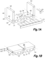
- the proposed extension module only consists of a floor panel 30, two side panels 40, a first coupling 10 which allows fixing the floor panel 30 to a building façade, and two second couplings 20 which allow fixing the two side panels 40 to the building façade.
- the floor panel 30 is a panel with a rectangular outline that defines a flat transitable top surface 34 and is demarcated by an inner edge 31, intended for being arranged facing the building façade and placed against same through the first coupling 10, an outer edge 33 parallel to the inner edge 31, and two side edges 32 perpendicular to the inner edge 31.
- the floor panel 30 also has a certain thickness corresponding to the height of each of the four edges defined above.
- Each side panel 40 also has a rectangular geometry defined between an inner edge 41 intended for being arranged facing the building façade and placed against same, a bottom edge 42 parallel and adjacent to a side edge 32 of the floor panel 30, and a top edge 43 parallel to the bottom edge 42.
- each side panel 40 is hinged to the floor panel 30 through a hinge 50 which allows the rotation of the side panel 40 with respect to the floor panel 30 about an axis parallel to the side edge 32 of the floor panel 30, and which is sized for the transmission of structural stresses between the side panel 40 and the floor panel 30.
- said hinge 50 can consist of flats perpendicular to said axis of rotation and protruding from the floor panel 30, at least partially inserted into each side panel 40, or part of the side panel 40 being contained between said flats, the flats being hinged to the side panel 40 by means of a pin concentric to the axis of rotation traversing holes provided in said flats.
- said flats protrude from the side panel 40 and are at least partially inserted into the floor panel 30, or part of the floor panel 30 is comprised between said flats, with the flats being hinged to the floor panel 30 by means of a pin traversing same.
- the flats protrude both from the floor panel 30 and from the side panel 40, with said flats being connected and hinged to one another by means of a pin concentric to the axis of rotation traversing same.
- hinge 50 Other embodiments of the hinge 50 are also contemplated.
- the first anchorage 10 consists of a horizontally elongated vertical flat provided to be arranged with one of its main faces facing the building façade and being placed against same and fixed thereto through a plurality of screws traversing said vertical flat anchored to the building, and preferably to a structural element thereof, for example, by means of chemical dowels.
- the other main face of the vertical flat opposite the main face facing the façade and placed against same, has a plurality of first coupling configurations 11 in the form of protruding tubular profiles parallel to one another and substantially perpendicular to said main face of the vertical flat, or defining a slight upward inclination.
- Said elongated profiles will preferably be hollow profiles welded to the vertical flat.
- the floor panel 30 integrates first receiving configurations 12 which, in this embodiment, consist of a plurality of elongated holes or aligned successions of holes, each elongated hole or each aligned succession of holes being sized and located to allow the snug insertion of one of the elongated profiles constituting the first coupling configuration 11, thereby connecting the floor panel 30 to the façade, supporting the floor panel 30.
- first receiving configurations 12 consist of a plurality of elongated holes or aligned successions of holes, each elongated hole or each aligned succession of holes being sized and located to allow the snug insertion of one of the elongated profiles constituting the first coupling configuration 11, thereby connecting the floor panel 30 to the façade, supporting the floor panel 30.
- Said first receiving configurations 12 are within the thickness of the floor panel 30 and accessible through inlet holes provided on the inner edge 31 of said floor panel 30, such that, in a position fixed to the façade, the inner edge 31 of the floor panel 30 will be facing the vertical flat.
- the size of the vertical flat will be the same as or smaller than the size of the inner edge 31 of the floor panel, such that, in a position fixed to the façade, the floor panel 30 will conceal the first anchorage 10.
- the second anchorages 20 are two independent anchorages, one for each side panel 40, which are the same as the first anchorage 10 but have a smaller horizontal length.
- each second anchorage 20 is an approximately square-shaped flat provided with a second coupling configuration 21 in the form of a single elongated profile protruding from said vertical flat, intended for being inserted into a second receiving configuration 22 contained in each side panel 40, in a position adjacent to its top edge 43.
- the second receiving configuration 22 will be the same as the first receiving configuration 12, i.e., it will be formed by an elongated hole or an aligned succession of elongated holes complementary to the elongated profile, accessible through an inlet hole provided on the inner edge 41 of the side panel 40.
- this arrangement allows fixing the first anchorage 10 and the second anchorages 20 in the intended positions on the façade, and then transporting the extension module with the side panels 40 in the horizontal position, shown in Figure 1B , lifting the side panels 40 to the vertical position, shown in Figure 1A , and proceeding to engage the first and second receiving configurations 12, 22 with the first and second coupling configurations 11, 21.
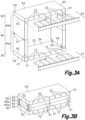
- FIGS 2A and 2B show a second embodiment which is the same as the first embodiment described above, but in which each side panel 40 is divided into a bottom half 40a and a top half 40b coupled to one another by means of an interposed intermediate hinge 51, which allows the rotation of the top half 40b with respect to the bottom half 40a about an axis parallel to the side edge 32 of the floor panel 30, i.e., the intermediate hinge 51 is parallel to the hinge 50 coupling the side panel 40 to the floor panel 30.
- Said intermediate hinge 51 will be sized for the transmission of structural stresses between the top and bottom halves 40a and 40b.
- Said intermediate hinge 51 may have a constitution similar to the hinge 50 described above.
- the bottom half 40a and the top half 40b will consist of separate vertical struts.
- One end of the vertical struts constituting the bottom half 40a will be inserted between the struts constituting the top half 40b, which will be located in a staggered manner, with all the struts of the two halves being connected and hinged to one another by means of a pin.
- This embodiment allows the top half 40b and the bottom half 40a to be inserted one into the other when the side panels are placed in the folded position, reducing the thickness of the assembly.
- the height of the side panels 40 must be the same as or smaller than half the length of the floor panel 30 in the direction of the inner edge 31 so as to allow a proper folding.
- this second embodiment allows the side panels 40 to have a height which can be the same as or smaller than the full length of the floor panel 30.
- each side panel 40 In addition to the second anchorages 20 described in the first embodiment which are arranged adjacent to the top edge 43 of each side panel 40, the possible of existence other two second anchorages 20 identical to the preceding ones, but located in a lower position, is envisaged in this embodiment.
- the bottom half 40a of each side panel 40 will have a receiving configuration 22, also accessible through the inner edge 41 of the side panel 40, in a position adjacent to the intermediate hinge 51.
- FIGS 3A and 3B show a third embodiment which is the same as the second embodiment, but in which a ceiling panel 60 coupled such that it is hinged, by means of a top hinge 52, to the top edge 43 of each side panel 40, has been included.
- Said hinge 52 allows the rotation of the side panel 40 with respect to the ceiling panel 60 about an axis parallel to the side edge 32 of the floor panel 30, i.e., it is a hinge parallel to the other hinges 50, 51 of the side panel 40.
- the ceiling panel 60 may be used merely for protection against the sun or other adverse weather conditions, or alternatively may also be fixed to the façade through said second anchorages 20, collaborating structurally in the structural support of the extension module, in which case said top hinge 52 will be sized for the transmission of structural stresses between the ceiling panel 60 and the side panel 40.
- the second anchorage 20 is identical to the first anchorage 10 described above, and the ceiling panel 60 has second receiving configurations 22 identical to the first receiving configurations 12 contained in the floor panel 30 described above.
- the side panels 40 lack second receiving configurations 22 and the corresponding second couplings 20. In such case, the side panels 40 will be fixed to the façade only through the ceiling panel 60 that will be the interposed element located between the second couplings 20 and the side panels 40.
- the extension module can also include an outer panel 80, which is located adjacent to the outer edge 33 of the floor panel 30, and above same, acting as a railing or curtain wall for the space defined by the extension module.
- the outer panel 80 is provided with a bottom edge and a top edge.
- the bottom edge will preferably be hinged to the floor panel 30 about an axis parallel to the outer edge 33 thereof by means of a rotary hinge coincident with or adjacent to the outer edge 33, allowing the outer panel 80 to be positioned in a horizontal position parallel to the flat top surface 34 of the floor panel 30, and in a vertical position perpendicular to the flat top surface 34 of the floor panel 30.
- the side panels 40 can be solid panels, i.e., lacking openings, although it is contemplated that they can be hollow in order to reduce their weight.
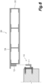
- the side panels 40 are triangular openworked panels, i.e., panels with openings but provided with diagonal struts.
- each side panel 40 will consist of a structural perimetral frame formed, for example, by welded metal profiles, and at least one diagonal profile which allows reinforcing said structural perimetral frame.
- Figure 4 shows different embodiments of triangular openworked side panels 40.
- a diagonal traversing the assembly consisting of the bottom and top halves 40a, 40b can be included, or at least one diagonal can be included in each of the two halves.
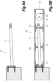
- Figures 5a and 5b shows an enlarged detail of the floor panel 30 and of the connection thereof with the first anchorage 10, according to a proposed embodiment.
- the floor panel 30 consists of a structural frame, for example, a metal, solid wood, or laminated wood structural frame.
- Said structural frame can also include intermediate cross members.
- the structural frame is formed by C-shaped metal profiles and by two I-shaped intermediate cross members.
- first coupling configuration 11 is a cylindrical elongated profile with the end beveled to facilitate its insertion
- each first receiving configuration 12 consists of an aligned succession of holes provided through the metal structural frame constituting the inner edge 31 of the floor panel 30 and through the two cross members mentioned above.
- the elongated profile has a slight upward inclination, i.e., the end of the elongated profile farthest away from the vertical flat is higher than its base, typically with an inclination of less than 10°.
- each of the aligned holes constituting the first receiving configuration 12 includes a rotary bushing with an eccentric hole, which allows the alignment of the holes with the inclination of the elongated profile.
- FIG. 5b also shows two optional characteristics of what is being proposed, i.e., the inclusion of a tightening device 70 to press the floor panel 30 against the façade, preventing the accidental removal thereof, and the inclusion of a windable curtain wall 90 wound about a windable curtain wall drum 91 included inside the floor panel 30.
- the tightening device 70 consists of a nut screwed onto the end of the elongated profile constituting the first coupling configuration 11.
- said nut screwed onto the elongated profile may be supported on a wear surface typically provided around one of the holes constituting the first receiving configuration 12. The tightening of the nut will pull the elongated profile and compress part of the floor panel 30 against the vertical flat of the first coupling or against the façade, ensuring the firm and immovable attachment thereof.
- the drum 91 about which the windable curtain wall 90 is wound will be parallel to the outer edge 33 of the floor panel 30 and will allow winding or unwinding the windable curtain wall 90 by means of the rotation thereof.
Landscapes
- Engineering & Computer Science (AREA)
- Architecture (AREA)
- Physics & Mathematics (AREA)
- Electromagnetism (AREA)
- Civil Engineering (AREA)
- Structural Engineering (AREA)
- Finishing Walls (AREA)
- Floor Finish (AREA)
- Joining Of Building Structures In Genera (AREA)
Claims (15)
- Vorgefertigtes Erweiterungsmodul und komplementäre Verankerungen zur freitragenden Befestigung an einer Gebäudefassade, umfassend:eine starre Bodenplatte (30), die einen strukturellen Bodenrahmen integriert und eine flache obere Oberfläche (34), eine Innenkante (31), die bereitgestellt wird, um der Gebäudefassade zugewandt angeordnet zu werden, wenn das Modul daran befestigt ist, zwei Seitenkanten (32) senkrecht zu der Innenkante (31) und eine zwischen den Seitenkanten (32) umfasste Außenkante (33) beinhaltet;zwei starre Seitenplatten (40), die jeweils einen strukturellen Seitenrahmen integrieren und mit einer Unterkante (42), einer Oberkante (43) und einer Innenkante (41) bereitgestellt werden, die bereitgestellt werden, um der Gebäudefassade zugewandt angeordnet zu werden, wenn das Modul daran befestigt ist, wobei jede der Seitenplatten (40) die Unterkante (42) davon mit der Bodenplatte (30) um eine Achse parallel zu den Seitenkanten (32) der Bodenplatte (30) mittels eines Gelenks (50) angelenkt hat, das mit einer der Seitenkanten (32) zusammenfällt oder ihr benachbart ist, wobei die Seitenplatten (40) in einer Horizontalposition parallel zu der flachen oberen Oberfläche (34) der Bodenplatte (30) und in einer Vertikalposition senkrecht zu der flachen oberen Oberfläche (34) der Bodenplatte (30) positioniert werden können;wobei die komplementären Verankerungen mindestens eine erste Verankerung (10) und mindestens eine zweite Verankerung (20) sind, und wobei die mindestens eine erste Verankerung (10) an einer Gebäudefassade anschraubbar ist;dadurch gekennzeichnet, dass die mindestens eine erste Verankerung (10) mit ersten Kopplungskonfigurationen (11) bereitgestellt wird, die durch mehrere parallele langgestreckte Profile gebildet werden, die von der ersten Verankerung in einer Richtung nahezu parallel zu den Seitenkanten der Bodenplatte hervorstehen oder eine Aufwärtsneigung bilden, wobei die ersten Kopplungskonfigurationen (11) komplementär zu ersten Aufnahmekonfigurationen (12) sind, die in der Bodenplatte (30) enthalten und durch die Innenkante (31) davon zugänglich sind, und in diese einsetzbar sind,die ersten Aufnahmekonfigurationen (12) langgestreckte Gehäuse oder ausgerichtete Abfolgen von Gehäusen sind, die strukturell mit dem strukturellen Bodenrahmen integriert sind,jedes langgestreckte Gehäuse oder jede ausgerichtete Abfolge von Gehäusen für das dichte Einsetzen eines langgestreckten Profils der ersten Kopplungskonfigurationen (11) in einer Richtung senkrecht zur Fassade konfiguriert ist;die mindestens eine zweite Verankerung (20) oberhalb der ersten Verankerung (10) an der Gebäudefassade anschraubbar ist und mit zweiten Kopplungskonfigurationen (21) bereitgestellt wird, die direkt und/oder über ein zwischengeschaltetes Element mit den beiden Seitenplatten (40) mittels zweiter, zu den zweiten Kopplungskonfigurationen (21) komplementärer Aufnahmekonfigurationen (22) verbindbar sind und in welche die zweiten Kopplungskonfigurationen (21) einsetzbar sind, wenn sich die Seitenplatten (40) in der Vertikalposition befinden; und wobeijedes Gelenk (50) strukturell am strukturellen Bodenrahmen und am strukturellen Seitenrahmen fixiert und für die Übertragung struktureller Spannungen zwischen ihnen dimensioniert ist.
- Vorgefertigtes Erweiterungsmodul gemäß Anspruch 1, wobei die zweiten Kopplungskonfigurationen (21) mehrere langgestreckte Profile sind, die aus der zweiten Verankerung hervorstehen oder aus der zweiten Verankerung hervorstehen und eine Aufwärtsneigung bilden, und wobei die zweiten Aufnahmekonfigurationen (22) langgestreckte Gehäuse oder ausgerichtete Abfolgen von Gehäusen sind, wobei jedes langgestreckte Gehäuse oder jede ausgerichtete Abfolge von Gehäusen für das dichte Einsetzen eines langgestreckten Profils konfiguriert ist oder für das dichte Einsetzen eines langgestreckten Profils konfiguriert ist, das einen Aufwärtspfad bildet, mit derselben oder einer größeren Neigung in Bezug auf die langgestreckten Profile.
- Vorgefertigtes Erweiterungsmodul gemäß Anspruch 1 oder 2, wobei die Verbindung zwischen den ersten Kopplungskonfigurationen (11) und den ersten Aufnahmekonfigurationen (12) eine Spannvorrichtung (70) beinhaltet, welche die ersten Kopplungskonfigurationen (12) zieht, wobei mindestens ein Teil der Bodenplatte (30), welche die ersten Aufnahmekonfigurationen (12) enthält, gegen die mindestens eine erste Verankerung (10) und/oder gegen die Fassade komprimiert wird; und/oder die Verbindung zwischen den zweiten Kopplungskonfigurationen (21) und den zweiten Aufnahmekonfigurationen (22) eine Spannvorrichtung beinhaltet, welche die zweiten Kopplungskonfigurationen (21) zieht, wobei mindestens ein Teil der Platte, welche die zweiten Aufnahmekonfigurationen (22) enthält, gegen die mindestens eine zweite Verankerung (20) und/oder gegen die Fassade komprimiert wird.
- Vorgefertigtes Erweiterungsmodul gemäß Anspruch 3, wobei die Spannvorrichtung (70) ein Element umfasst, das auf die ersten Kopplungskonfigurationen (11) geschraubt ist und auf einer Verschleißoberfläche der Bodenplatte (30) senkrecht zu den langgestreckten Elementen, welche die erste Kopplungskonfiguration (11) ausmachen, abgestützt ist.
- Vorgefertigtes Erweiterungsmodul gemäß einem der vorhergehenden Ansprüche, wobei jeder strukturelle Seitenrahmen eine untere Hälfte (40a) und eine obere Hälfte (40b) beinhaltet, die um eine Achse parallel zu den Seitenkanten (32) der Bodenplatte (30) mittels eines Zwischengelenks (51) angelenkt sind, das strukturell mit dem Abschnitt des strukturellen Seitenrahmens, der die untere Hälfte (40a) ausmacht, und mit dem Abschnitt, der die obere Hälfte (40b) ausmacht, gekoppelt ist, dimensioniert für die Übertragung von strukturellen Spannungen zwischen ihnen, wobei die Seitenplatten (40) in einer gefalteten Position, in der die untere und die obere Hälfte (40a, 40b) einander zugewandt sind und übereinander liegen, und in einer ausgezogenen Position positioniert werden können, in der die untere und die obere Hälfte (40a, 40b) nacheinander ausgerichtet und koplanar sind.
- Vorgefertigtes Erweiterungsmodul gemäß einem der vorhergehenden Ansprüche, wobei das erwähnte zwischengeschaltete Element, das sich zwischen der zweiten Verankerung (20) und den Seitenplatten (40) befindet, eine starre Deckenplatte (60) ist, die einen strukturellen Deckenrahmen parallel zur Bodenplatte (30) integriert und eine Innenkante (61), die dazu bereitgestellt ist, der Gebäudefassade zugewandt angeordnet zu werden, wenn das Modul daran befestigt ist, zwei Seitenkanten (62) senkrecht zur Innenkante (61) und eine zwischen den Seitenkanten (62) umfasste Außenkante (63) beinhaltet, wobei jede der Oberkanten (43) der Seitenplatten (40) an der Deckenplatte (60) um eine zu den Seitenkanten (62) der Deckenplatte (60) parallele Achse mittels eines Gelenks (52) angelenkt ist, das strukturell am strukturellen Deckenrahmen und am strukturellen Seitenrahmen fixiert und für die Übertragung von strukturellen Spannungen zwischen ihnen dimensioniert ist.
- Vorgefertigtes Erweiterungsmodul gemäß einem der vorhergehenden Ansprüche, wobei die zweiten Aufnahmekonfigurationen (22) in den Seitenplatten (40) enthalten sind, die strukturell mit dem strukturellen Seitenrahmen gekoppelt und über die Innenkante (41) der Seitenplatten (40) zugänglich sind, und/oder in der Deckenplatte (60) enthalten sind, die strukturell mit dem strukturellen Deckenrahmen gekoppelt und über die Innenkante (61) der Deckenplatte (60) zugänglich ist.
- Vorgefertigtes Erweiterungsmodul gemäß einem der vorhergehenden Ansprüche, wobei es ferner eine Außenplatte (80) beinhaltet, die mit einer Unterkante und einer Oberkante bereitgestellt wird, wobei die Unterkante der Außenplatte (80) an der Bodenplatte (30) um eine Achse parallel zu der Außenkante (33) davon mittels eines Drehgelenks angelenkt ist, das mit der Außenkante (33) zusammenfällt oder ihr benachbart ist, wobei die Außenplatte (80) in einer Horizontalposition parallel zu der flachen oberen Oberfläche (34) der Bodenplatte (30) und in einer Vertikalposition senkrecht zu der flachen oberen Oberfläche (34) der Bodenplatte (30) positioniert werden kann.
- Vorgefertigtes Erweiterungsmodul gemäß einem der vorhergehenden Ansprüche, wobei die Bodenplatte (30) und/oder die Deckenplatte (60) eine wickelbare Vorhangwand (90) enthält, die um eine wickelbare Vorhangwandtrommel (91) gewickelt ist, die um eine Achse parallel zur Außenkante (33, 63) der entsprechenden Bodenplatte (30) und/oder Deckenplatte (60) und benachbart zu dieser rotierbar ist.
- Vorgefertigtes Erweiterungsmodul gemäß Anspruch 9, wobei jede Seitenplatte (40) eine Vertikalführung zur Führung eines Endes der wickelbaren Vorhangwand beinhaltet.
- Vorgefertigtes Erweiterungsmodul gemäß einem der vorhergehenden Ansprüche, wobei eine Oberfläche, die dazu bestimmt ist, gegen die Fassade der mindestens einen ersten Verankerung (10) und/oder der mindestens einen zweiten Verankerung (20) angeordnet zu werden, und/oder eine Oberfläche der Innenkante (31, 41, 61) der Bodenplatte (30), der Seitenplatten (40) und/oder der Deckenplatte (60) eine Schicht aus Isoliermaterial zum Unterbrechen der Wärmebrücke beinhaltet.
- Vorgefertigtes Erweiterungsmodul gemäß einem der vorhergehenden Ansprüche, wobei mindestens einige der angelenkten Kupplungen (50, 51, 52) eine Verriegelungsvorrichtung beinhalten, die sie in der entfalteten Position verriegelt, um das entfaltete Modul anzuheben.
- Vorgefertigtes Erweiterungsmodul gemäß einem der vorhergehenden Ansprüche, wobei das Modul Hebepunkte beinhaltet, die sich in den Seitenplatten und/oder in der Deckenplatte befinden.
- Installationsverfahren eines vorgefertigten Erweiterungsmoduls und komplementärer Verankerungen gemäß einem der vorhergehenden Ansprüche, wobei das Verfahren beinhaltet:Anschrauben der mindestens einen ersten Verankerung (10) an der Gebäudefassade und Anschrauben der mindestens einen zweiten Verankerung (20) an der Gebäudefassade oberhalb der ersten Verankerung (10);Transportieren des Moduls in der gefalteten Position zu dem Gebäude,Entfalten des Moduls durch Platzieren der Seitenplatten in der Vertikalposition,Anheben des entfalteten Moduls und Fixieren der ersten Kopplungskonfigurationen (11) an den ersten Aufnahmekonfigurationen (12) und der zweiten Kopplungskonfigurationen (21) an den zweiten Aufnahmekonfigurationen (22).
- Verfahren gemäß Anspruch 14, wobei das Fixieren der ersten und zweiten Kopplungskonfigurationen (11, 21) an den ersten und zweiten Aufnahmekonfigurationen (12, 22) mittels einer Bewegung in einer Richtung nahezu senkrecht zur Fassade durchgeführt wird.
Applications Claiming Priority (2)
| Application Number | Priority Date | Filing Date | Title |
|---|---|---|---|
| ES202030764A ES2891781A1 (es) | 2020-07-22 | 2020-07-22 | Modulo de extension prefabricado acoplable en voladizo a una fachada de un edificio |
| PCT/ES2021/070542 WO2022018317A1 (es) | 2020-07-22 | 2021-07-20 | Módulo de extensión prefabricado acoplable en voladizo a una fachada de un edificio y método de instalación |
Publications (4)
| Publication Number | Publication Date |
|---|---|
| EP4187033A1 EP4187033A1 (de) | 2023-05-31 |
| EP4187033A4 EP4187033A4 (de) | 2023-12-06 |
| EP4187033C0 EP4187033C0 (de) | 2024-09-04 |
| EP4187033B1 true EP4187033B1 (de) | 2024-09-04 |
Family
ID=79729087
Family Applications (1)
| Application Number | Title | Priority Date | Filing Date |
|---|---|---|---|
| EP21846994.8A Active EP4187033B1 (de) | 2020-07-22 | 2021-07-20 | Vorgefertigtes erweiterungsmodul und komplementäre verankerungen zur freitragenden befestigung an einer gebäudefassade und installationsverfahren |
Country Status (3)
| Country | Link |
|---|---|
| EP (1) | EP4187033B1 (de) |
| ES (2) | ES2891781A1 (de) |
| WO (1) | WO2022018317A1 (de) |
Families Citing this family (1)
| Publication number | Priority date | Publication date | Assignee | Title |
|---|---|---|---|---|
| DE102023127232A1 (de) * | 2023-10-06 | 2023-12-21 | Leviat Ag | Bauwerk mit einem tragenden Bauwerksteil und mindestens einem an dem Bauwerksteil festgelegten, auskragenden Baukörper |
Family Cites Families (8)
| Publication number | Priority date | Publication date | Assignee | Title |
|---|---|---|---|---|
| GB189404873A (en) * | 1894-03-08 | 1895-01-12 | James Moffat | Improvements in and relating to Portable Balconies for Window Cleaning and other Purposes. |
| GB1402359A (en) * | 1971-12-29 | 1975-08-06 | Misawa Homes Co | Prefabricated buildings |
| GB8416713D0 (en) * | 1984-06-30 | 1984-08-01 | Forsyth I | Fold away container |
| JP3227544B2 (ja) * | 1992-07-28 | 2001-11-12 | 三和シヤッター工業株式会社 | バルコニー |
| JPH07127126A (ja) * | 1993-11-09 | 1995-05-16 | Sekisui Chem Co Ltd | ユニット式バルコニー |
| JP2002088902A (ja) * | 2000-09-18 | 2002-03-27 | Misawa Homes Co Ltd | バルコニーの施工方法 |
| GB2507365B (en) * | 2013-04-22 | 2014-10-22 | Sapphire Balustrades Ltd | Balcony |
| EP3061880B1 (de) * | 2015-02-24 | 2019-04-03 | FEHR Groupe | Fertigbalkon mit rippen |
-
2020
- 2020-07-22 ES ES202030764A patent/ES2891781A1/es active Pending
-
2021
- 2021-07-20 WO PCT/ES2021/070542 patent/WO2022018317A1/es not_active Ceased
- 2021-07-20 ES ES21846994T patent/ES2999162T3/es active Active
- 2021-07-20 EP EP21846994.8A patent/EP4187033B1/de active Active
Also Published As
| Publication number | Publication date |
|---|---|
| ES2999162T3 (en) | 2025-02-24 |
| ES2891781A1 (es) | 2022-01-31 |
| EP4187033A4 (de) | 2023-12-06 |
| EP4187033C0 (de) | 2024-09-04 |
| WO2022018317A1 (es) | 2022-01-27 |
| EP4187033A1 (de) | 2023-05-31 |
Similar Documents
| Publication | Publication Date | Title |
|---|---|---|
| CA2900392C (en) | Mounting facade elements for multi-storey buildings | |
| US8806833B2 (en) | Structural reinforcing system components | |
| US20130232887A1 (en) | Assembly of prefabricated elements to form a prefabricated building with at least two floors and related building and installation process | |
| US9631379B2 (en) | Building construction method and lifting device | |
| CA2619786C (en) | Prefabricated building structure with collapsible roof sections | |
| US20130055671A1 (en) | Prefabricated modular building units | |
| US20080016798A1 (en) | Unitized Structural Frame | |
| US20150159393A1 (en) | Secure shelter with trapezoidal walls | |
| EP3037605A1 (de) | Hochhaus und wartungsverfahren dafür | |
| US20080072501A1 (en) | Perimeter Wall Panels for an Air Supported Structure | |
| US20230014744A1 (en) | Method of Construction | |
| EP4187033B1 (de) | Vorgefertigtes erweiterungsmodul und komplementäre verankerungen zur freitragenden befestigung an einer gebäudefassade und installationsverfahren | |
| US20060048458A1 (en) | Storm shelter and vault with transport system | |
| AU2009222603A1 (en) | Construction of multi-storey modular buildings | |
| US10513848B2 (en) | Building component | |
| EP3006647A1 (de) | Hochhaus und wartungsverfahren dafür | |
| US11680418B2 (en) | Assembly for erecting and dismantling a common tower adjacent a building structure and a method of erecting and dismantling the same | |
| CN1195385A (zh) | 三点式屋顶 | |
| EP1380532B1 (de) | Verfahren zum nachträglichen Einbau eines Personenaufzugs | |
| US20080017329A1 (en) | Unitized Structural Frame | |
| AU2018417116A1 (en) | Building including a cantilevered structure | |
| FI131226B1 (fi) | Ballistisen suojan perustus ja menetelmä ballistisen suojan perustuksen valmistamiseksi | |
| JP7421890B2 (ja) | 建物 | |
| ES1304332U (es) | Modulo de extension prefabricado acoplable en voladizo a una fachada de un edificio | |
| BE511396A (de) |
Legal Events
| Date | Code | Title | Description |
|---|---|---|---|
| STAA | Information on the status of an ep patent application or granted ep patent |
Free format text: STATUS: THE INTERNATIONAL PUBLICATION HAS BEEN MADE |
|
| PUAI | Public reference made under article 153(3) epc to a published international application that has entered the european phase |
Free format text: ORIGINAL CODE: 0009012 |
|
| STAA | Information on the status of an ep patent application or granted ep patent |
Free format text: STATUS: REQUEST FOR EXAMINATION WAS MADE |
|
| 17P | Request for examination filed |
Effective date: 20230221 |
|
| AK | Designated contracting states |
Kind code of ref document: A1 Designated state(s): AL AT BE BG CH CY CZ DE DK EE ES FI FR GB GR HR HU IE IS IT LI LT LU LV MC MK MT NL NO PL PT RO RS SE SI SK SM TR |
|
| DAV | Request for validation of the european patent (deleted) | ||
| DAX | Request for extension of the european patent (deleted) | ||
| A4 | Supplementary search report drawn up and despatched |
Effective date: 20231106 |
|
| RIC1 | Information provided on ipc code assigned before grant |
Ipc: E06B 9/40 20060101ALN20231030BHEP Ipc: E04F 10/02 20060101ALN20231030BHEP Ipc: E04B 1/344 20060101ALI20231030BHEP Ipc: E04B 1/00 20060101AFI20231030BHEP |
|
| R17P | Request for examination filed (corrected) |
Effective date: 20230221 |
|
| GRAP | Despatch of communication of intention to grant a patent |
Free format text: ORIGINAL CODE: EPIDOSNIGR1 |
|
| STAA | Information on the status of an ep patent application or granted ep patent |
Free format text: STATUS: GRANT OF PATENT IS INTENDED |
|
| RIC1 | Information provided on ipc code assigned before grant |
Ipc: E06B 9/40 20060101ALN20240228BHEP Ipc: E04F 10/02 20060101ALN20240228BHEP Ipc: E04B 1/344 20060101ALI20240228BHEP Ipc: E04B 1/00 20060101AFI20240228BHEP |
|
| INTG | Intention to grant announced |
Effective date: 20240322 |
|
| GRAS | Grant fee paid |
Free format text: ORIGINAL CODE: EPIDOSNIGR3 |
|
| GRAA | (expected) grant |
Free format text: ORIGINAL CODE: 0009210 |
|
| STAA | Information on the status of an ep patent application or granted ep patent |
Free format text: STATUS: THE PATENT HAS BEEN GRANTED |
|
| AK | Designated contracting states |
Kind code of ref document: B1 Designated state(s): AL AT BE BG CH CY CZ DE DK EE ES FI FR GB GR HR HU IE IS IT LI LT LU LV MC MK MT NL NO PL PT RO RS SE SI SK SM TR |
|
| REG | Reference to a national code |
Ref country code: GB Ref legal event code: FG4D |
|
| REG | Reference to a national code |
Ref country code: CH Ref legal event code: EP |
|
| REG | Reference to a national code |
Ref country code: IE Ref legal event code: FG4D |
|
| REG | Reference to a national code |
Ref country code: DE Ref legal event code: R096 Ref document number: 602021018478 Country of ref document: DE |
|
| U01 | Request for unitary effect filed |
Effective date: 20241003 |
|
| U07 | Unitary effect registered |
Designated state(s): AT BE BG DE DK EE FI FR IT LT LU LV MT NL PT RO SE SI Effective date: 20241025 |
|
| PG25 | Lapsed in a contracting state [announced via postgrant information from national office to epo] |
Ref country code: NO Free format text: LAPSE BECAUSE OF FAILURE TO SUBMIT A TRANSLATION OF THE DESCRIPTION OR TO PAY THE FEE WITHIN THE PRESCRIBED TIME-LIMIT Effective date: 20241204 |
|
| PG25 | Lapsed in a contracting state [announced via postgrant information from national office to epo] |
Ref country code: PL Free format text: LAPSE BECAUSE OF FAILURE TO SUBMIT A TRANSLATION OF THE DESCRIPTION OR TO PAY THE FEE WITHIN THE PRESCRIBED TIME-LIMIT Effective date: 20240904 Ref country code: GR Free format text: LAPSE BECAUSE OF FAILURE TO SUBMIT A TRANSLATION OF THE DESCRIPTION OR TO PAY THE FEE WITHIN THE PRESCRIBED TIME-LIMIT Effective date: 20241205 |
|
| PG25 | Lapsed in a contracting state [announced via postgrant information from national office to epo] |
Ref country code: HR Free format text: LAPSE BECAUSE OF FAILURE TO SUBMIT A TRANSLATION OF THE DESCRIPTION OR TO PAY THE FEE WITHIN THE PRESCRIBED TIME-LIMIT Effective date: 20240904 |
|
| PG25 | Lapsed in a contracting state [announced via postgrant information from national office to epo] |
Ref country code: RS Free format text: LAPSE BECAUSE OF FAILURE TO SUBMIT A TRANSLATION OF THE DESCRIPTION OR TO PAY THE FEE WITHIN THE PRESCRIBED TIME-LIMIT Effective date: 20241204 |
|
| PG25 | Lapsed in a contracting state [announced via postgrant information from national office to epo] |
Ref country code: RS Free format text: LAPSE BECAUSE OF FAILURE TO SUBMIT A TRANSLATION OF THE DESCRIPTION OR TO PAY THE FEE WITHIN THE PRESCRIBED TIME-LIMIT Effective date: 20241204 Ref country code: PL Free format text: LAPSE BECAUSE OF FAILURE TO SUBMIT A TRANSLATION OF THE DESCRIPTION OR TO PAY THE FEE WITHIN THE PRESCRIBED TIME-LIMIT Effective date: 20240904 Ref country code: NO Free format text: LAPSE BECAUSE OF FAILURE TO SUBMIT A TRANSLATION OF THE DESCRIPTION OR TO PAY THE FEE WITHIN THE PRESCRIBED TIME-LIMIT Effective date: 20241204 Ref country code: HR Free format text: LAPSE BECAUSE OF FAILURE TO SUBMIT A TRANSLATION OF THE DESCRIPTION OR TO PAY THE FEE WITHIN THE PRESCRIBED TIME-LIMIT Effective date: 20240904 Ref country code: GR Free format text: LAPSE BECAUSE OF FAILURE TO SUBMIT A TRANSLATION OF THE DESCRIPTION OR TO PAY THE FEE WITHIN THE PRESCRIBED TIME-LIMIT Effective date: 20241205 |
|
| REG | Reference to a national code |
Ref country code: ES Ref legal event code: FG2A Ref document number: 2999162 Country of ref document: ES Kind code of ref document: T3 Effective date: 20250224 |
|
| PG25 | Lapsed in a contracting state [announced via postgrant information from national office to epo] |
Ref country code: IS Free format text: LAPSE BECAUSE OF FAILURE TO SUBMIT A TRANSLATION OF THE DESCRIPTION OR TO PAY THE FEE WITHIN THE PRESCRIBED TIME-LIMIT Effective date: 20250104 |
|
| PG25 | Lapsed in a contracting state [announced via postgrant information from national office to epo] |
Ref country code: SM Free format text: LAPSE BECAUSE OF FAILURE TO SUBMIT A TRANSLATION OF THE DESCRIPTION OR TO PAY THE FEE WITHIN THE PRESCRIBED TIME-LIMIT Effective date: 20240904 |
|
| PG25 | Lapsed in a contracting state [announced via postgrant information from national office to epo] |
Ref country code: CZ Free format text: LAPSE BECAUSE OF FAILURE TO SUBMIT A TRANSLATION OF THE DESCRIPTION OR TO PAY THE FEE WITHIN THE PRESCRIBED TIME-LIMIT Effective date: 20240904 |
|
| PG25 | Lapsed in a contracting state [announced via postgrant information from national office to epo] |
Ref country code: SK Free format text: LAPSE BECAUSE OF FAILURE TO SUBMIT A TRANSLATION OF THE DESCRIPTION OR TO PAY THE FEE WITHIN THE PRESCRIBED TIME-LIMIT Effective date: 20240904 |
|
| PLBE | No opposition filed within time limit |
Free format text: ORIGINAL CODE: 0009261 |
|
| STAA | Information on the status of an ep patent application or granted ep patent |
Free format text: STATUS: NO OPPOSITION FILED WITHIN TIME LIMIT |
|
| 26N | No opposition filed |
Effective date: 20250605 |
|
| U20 | Renewal fee for the european patent with unitary effect paid |
Year of fee payment: 5 Effective date: 20250724 |
|
| PGFP | Annual fee paid to national office [announced via postgrant information from national office to epo] |
Ref country code: ES Payment date: 20250904 Year of fee payment: 5 |