EP4186790B1 - Flugzeugfahrwerkschachttür - Google Patents
Flugzeugfahrwerkschachttür Download PDFInfo
- Publication number
- EP4186790B1 EP4186790B1 EP22208815.5A EP22208815A EP4186790B1 EP 4186790 B1 EP4186790 B1 EP 4186790B1 EP 22208815 A EP22208815 A EP 22208815A EP 4186790 B1 EP4186790 B1 EP 4186790B1
- Authority
- EP
- European Patent Office
- Prior art keywords
- landing gear
- door
- aircraft
- thickness
- bay
- Prior art date
- Legal status (The legal status is an assumption and is not a legal conclusion. Google has not performed a legal analysis and makes no representation as to the accuracy of the status listed.)
- Active
Links
Images


Classifications
-
- B—PERFORMING OPERATIONS; TRANSPORTING
- B64—AIRCRAFT; AVIATION; COSMONAUTICS
- B64C—AEROPLANES; HELICOPTERS
- B64C25/00—Alighting gear
- B64C25/001—Devices not provided for in the groups B64C25/02 - B64C25/68
-
- B—PERFORMING OPERATIONS; TRANSPORTING
- B64—AIRCRAFT; AVIATION; COSMONAUTICS
- B64C—AEROPLANES; HELICOPTERS
- B64C25/00—Alighting gear
- B64C25/02—Undercarriages
- B64C25/08—Undercarriages non-fixed, e.g. jettisonable
- B64C25/10—Undercarriages non-fixed, e.g. jettisonable retractable, foldable, or the like
- B64C25/16—Fairings movable in conjunction with undercarriage elements
-
- B—PERFORMING OPERATIONS; TRANSPORTING
- B64—AIRCRAFT; AVIATION; COSMONAUTICS
- B64C—AEROPLANES; HELICOPTERS
- B64C25/00—Alighting gear
- B64C25/02—Undercarriages
- B64C25/08—Undercarriages non-fixed, e.g. jettisonable
- B64C25/10—Undercarriages non-fixed, e.g. jettisonable retractable, foldable, or the like
- B64C25/18—Operating mechanisms
- B64C25/20—Operating mechanisms mechanical
-
- B—PERFORMING OPERATIONS; TRANSPORTING
- B64—AIRCRAFT; AVIATION; COSMONAUTICS
- B64C—AEROPLANES; HELICOPTERS
- B64C25/00—Alighting gear
- B64C25/32—Alighting gear characterised by elements which contact the ground or similar surface
- B64C25/34—Alighting gear characterised by elements which contact the ground or similar surface wheeled type, e.g. multi-wheeled bogies
- B64C25/36—Arrangements or adaptations of wheels, tyres or axles in general
-
- G—PHYSICS
- G10—MUSICAL INSTRUMENTS; ACOUSTICS
- G10K—SOUND-PRODUCING DEVICES; METHODS OR DEVICES FOR PROTECTING AGAINST, OR FOR DAMPING, NOISE OR OTHER ACOUSTIC WAVES IN GENERAL; ACOUSTICS NOT OTHERWISE PROVIDED FOR
- G10K11/00—Methods or devices for transmitting, conducting or directing sound in general; Methods or devices for protecting against, or for damping, noise or other acoustic waves in general
- G10K11/16—Methods or devices for protecting against, or for damping, noise or other acoustic waves in general
- G10K11/161—Methods or devices for protecting against, or for damping, noise or other acoustic waves in general in systems with fluid flow
-
- B—PERFORMING OPERATIONS; TRANSPORTING
- B64—AIRCRAFT; AVIATION; COSMONAUTICS
- B64C—AEROPLANES; HELICOPTERS
- B64C25/00—Alighting gear
- B64C25/001—Devices not provided for in the groups B64C25/02 - B64C25/68
- B64C2025/003—Means for reducing landing gear noise, or turbulent flow around it, e.g. landing gear doors used as deflectors
Definitions
- landing gear bay door arrangements often comprising a number of doors used to open and close the landing gear bay to allow a landing gear to deploy from the bay.
- These doors are often generally planar (see US 8708272 , for example) and may be designed to have an external side that is contoured to match the surrounding contour of the aircraft where it is located. This is done to maintain the aerodynamic profile of the part of the aircraft where the door is located, when the door is closed.
- the aerodynamic profile will typically be shaped so as to reduce the drag of the aircraft when the landing gear bay doors are closed.
- upstream corresponds to a forward/fore region and downstream corresponds to a backward/aft region.
- first side directly faces the one side of a main leg of the landing gear, it will be directly facing laterally (starboard or port-wards) and so at 90 degrees to the aircraft longitudinal axis.
- the door itself will be roughly aligned with the direction of the aircraft longitudinal axis, when open.
- Height corresponds to the dimension in the upward/vertical (z) direction, in relation to a level orientation of the aircraft with respect to the ground.
- the first side provides one half of an aerofoil profile and wherein the second side provides a corresponding other half of an aerofoil profile.
- the inner side of the door has a profile that matches one half of an aerofoil profile.
- the aerofoil profile may run along a longitudinal direction of the door, in use.
- the outer side of the door has a profile that matches one half of an aerofoil profile.
- both inner and outer sides of the door may provide respective halves of an aerofoil profile.
- the half provided by the outer side may be the opposite half to the inner side of the door, for example an upper half of an aerofoil profile.
- the aerofoil profile may run along a longitudinal direction of the door, in use.
- the leading edge of the complete aerofoil profile may be located at an upstream edge of the door, when open.
- a leading edge of the aerofoil profile is located at an upstream edge of the door, when open.
- the aerofoil profile has a height corresponding to at least 80%, preferably at least 90%, of the height of the door.
- the aerofoil profile has a camber.
- Such a curved bulged portion acts to significantly slow down airflow and hence, reduce noise.
- the bulged portion may be located towards a rear/trailing end of the aerofoil profile. For example, in embodiments, it may be more than halfway along the length of the aerofoil profile from the leading edge.
- the first side of the aerofoil profile is provided with the bulged portion.
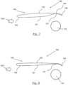
- the arrangement 100 comprises a landing gear main leg 110, which, in use, is pivotally connected to an aircraft by a pivot mechanism 113 at the top of the leg. At the bottom of the leg is an axle, which mounts two landing gear wheels, only one (labelled 131) seen in Figure 1 .
- the wheels roll in a fore/aft (or longitudinal) direction.
- a side stay (not seen) is pivotally mounted on the leg 110 and also to the aircraft, in use.
- the landing gear main leg 110, side stay and axle/wheels are entirely conventional and comprise various other elements/features, such as oleo struts, support arms/braces, electrical installations, brake assemblies, actuators etc. which will not be described here.
- the arrangement 100 also includes a landing gear bay door 140.
- the door 140 has an outer side 142 (facing away from the leg 110) and an inner side 141 (facing the leg 110). Slightly below the top edge 143 on the inner side 141 is an attachment mechanism to mount the door 140 to the leg 110.
- the door 140 has a front edge 145 and a rear edge 146.
- the rear edge is the full door height but the front edge 145 is slightly shorter. It is the longest dimension (i.e. at the rear edge) that defines the door height.
- the front edge 145 is shorter as the bottom edge 144 of the door 140 is shaped to curve upwards towards the front edge 145.
- the arrangement 100 is shown in relation to an oncoming airflow 1001.
- a unique feature of the door 140 is that the door 140 has a cross-sectional shape (in plan view) of that of an aerofoil.
- the front edge 145 has the shape of a rounded leading edge of an aerofoil and the shape tapers towards a trailing edge at the rear edge 146.
- the aerofoil shape provided has a planar outer side 142.
- the planar outer side 142 forms an outside contour of the aircraft. It, in fact, provides a contour that matches/follows that of the surrounding generally planar contour of the aircraft.
- the aerofoil shape also has a straight edge at the rear edge 146 so as to provide a finite thickness at that edge 146.
- the aerofoil profile shape is provided on the door along its entire height/length (i.e. from the top 143 to the bottom 144).
- the landing gear leg is offset from the aerofoil door 140 by an offset distance (labelled as 148) of 50mm.
- Figure 5 shows a schematic plan view of a landing gear arrangement according to fourth embodiment of the invention.
- the fourth embodiment is similar to the third embodiment and only the differences will be described.
- a side view of the fourth embodiment is in fact the same as the side view of the third embodiment (i.e. Figure 1 ).
- the landing gear leg is offset from the aerofoil door 140 by an offset distance (labelled as 148) of 100mm.
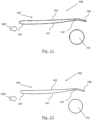
- Figure 7 shows a schematic plan view of a landing gear arrangement 100 according to sixth embodiment of the invention.
- the sixth embodiment is similar to the fifth embodiment and only the differences will be described.
- a side view of the sixth embodiment is in fact the same as the side view of the fifth embodiment (i.e. Figure 1 ).
- the leading region of the outer side 142 is further outwards, corresponding to the level of the rear bulge of the fifth embodiment. This gives a much thicker forward region of the door 140. Hence, the outer side 142 is much more planar compared to that of the fifth embodiment. However, it still enables a concave shape in the inner side 141.
- the trailing edge 146 is located much further inwards (towards the leg 110). Hence, the concave shape of the inner side 141 can be retained with a substantially planar outer side 142 and with a thinner door 140 thickness.
- the outer side 142 extends further outwards at the bulge 149 so as to reduce the planar-ness of the outer surface whilst still providing a large concave-ness of the inner side 141.
- the landing gear leg may be offset from the aerofoil door by different offset distance, being greater or less than the figures stated herein, and the distance need not be exactly the same for the length of the leg.
- the landing gear leg 110 may have any suitable number of wheels, for example being greater than two.
Landscapes
- Engineering & Computer Science (AREA)
- Aviation & Aerospace Engineering (AREA)
- Mechanical Engineering (AREA)
- Physics & Mathematics (AREA)
- Chemical & Material Sciences (AREA)
- Combustion & Propulsion (AREA)
- Fluid Mechanics (AREA)
- Acoustics & Sound (AREA)
- Multimedia (AREA)
- Gears, Cams (AREA)
- Gear Transmission (AREA)
Claims (13)
- Luftfahrzeugfahrwerkschachttür (140), die Folgendes umfasst:i) einen Befestigungsmechanismus, der zum schwenkbaren Montieren der Tür (140) an einem Luftfahrzeug geeignet ist, so dass sich die Tür (140) zwischen einer geschlossenen Position, in der die Tür (140) zumindest teilweise einen Luftfahrzeugfahrwerkschacht verschließt, um ein Fahrwerk darin zu verstauen, und einer geöffneten Position, in der die Tür (140) den Fahrwerkschacht zumindest teilweise öffnet, um ein Ausfahren des Fahrwerks zu ermöglichen, bewegen kann,ii) eine erste Seite (141), die so angeordnet ist, dass sie in Relation zu dem Luftfahrzeugfahrwerkschacht nach innen weist, wenn die Tür (140) geschlossen ist, und zu einer Seite eines Hauptbeins (110) des Fahrwerks weist, wenn die Tür (140) geöffnet ist und das Fahrwerk ausgefahren ist, undiii) eine zweite gegenüberliegende Seite (142), die so angeordnet ist, dass sie in Relation zu dem Fahrwerkschacht nach außen weist, wenn die Tür (140) geschlossen ist, und somit eine aerodynamische Außenfläche des Luftfahrzeugs bereitstellt, und von dem Hauptbein (110) des Fahrwerks weg weist, wenn die Tür (140) geöffnet ist und das Fahrwerk ausgefahren ist,wobei die von der ersten und der zweiten Seite (141, 142) gebildete Form ein Tragflächenprofil der Tür (140) bereitstellt,dadurch gekennzeichnet, dass die Form der Tür (140) derart ist, dass entlang eines Längsschnitts der Tür (140), wenn sie geöffnet ist, die Dicke der Tür (140) für mindestens ein Fünftel ihrer Länge in der Längsrichtung größer als eine erste Dicke ist und für mindestens ein Fünftel ihrer Länge in der Längsrichtung kleiner als eine zweite Dicke ist, wobei die erste Dicke mindestens doppelt so groß wie die zweite Dicke ist.
- Luftfahrzeugfahrwerkschachttür (140) nach Anspruch 1, wobei die Hinterkante des Tragflächenprofils verjüngt ist.
- Luftfahrzeugfahrwerkschachttür (140) nach einem der vorhergehenden Ansprüche, wobei ein Bereich des Tragflächenprofils mit einem gewölbten Abschnitt (149) versehen ist, der zu der zweiten Seite (142) der Tür (140) hin gewölbt ist.
- Luftfahrzeugfahrwerkschachttür (140) nach Anspruch 3, wobei die erste Seite (141) des Tragflächenprofils mit dem gewölbten Abschnitt (149) versehen ist.
- Luftfahrzeugfahrwerkschachttür (140) nach Anspruch 4, wobei die zweite Seite (142) des Tragflächenprofils auch mit dem gewölbten Abschnitt (149) versehen ist.
- Luftfahrzeugfahrwerkschachttür (140) nach einem der vorhergehenden Ansprüche, wobei die Dicke der Tür (140) für mindestens die Hälfte ihrer Länge in der Längsrichtung größer als die erste Dicke ist und für mindestens ein Fünftel ihrer Länge in der Längsrichtung kleiner als die zweite Dicke ist.
- Luftfahrzeugfahrwerkschachttür (140) nach Anspruch 6, wobei die Dicke der Tür (140) für mindestens drei Fünftel ihrer Länge in der Längsrichtung größer als die erste Dicke ist und für mindestens ein Fünftel ihrer Länge in der Längsrichtung kleiner als die zweite Dicke ist.
- Luftfahrzeugfahrwerkschachttür (140) nach einem der vorhergehenden Ansprüche, wobei die Tür (140) eine bewegliche Komponente umfasst, die von einer ersten Position, wenn die Tür (140) geschlossen ist, in eine zweite Position, wenn die Tür (140) geöffnet ist, beweglich ist, und wobei sich die bewegliche Komponente in der zweiten Position derart bewegt, dass das Tragflächenprofil gebildet wird, vorzugsweise wobei die bewegliche Komponente eine Gedächtnisformkomponente ist und wobei die Gedächtnisformkomponente derart vorgespannt ist, dass sie sich in dem zweiten Abschnitt befindet, und in die erste Position gedrückt wird, wenn sich die Tür (140) schließt.
- Luftfahrzeugfahrwerkanordnung (100), die die Luftfahrzeugfahrwerkschachttür (140) nach einem der vorhergehenden Ansprüche und ein Fahrwerk beinhaltet, das ein Hauptfahrwerkbein (110) beinhaltet, wobei das Hauptfahrwerkbein (110) in Relation zu einem Luftfahrzeugfahrwerkschacht zwischen einer verstauten und einer ausgefahrenen Position schwenkbar montierbar ist, und umfassend eine Anzahl von Fahrwerksrädern (131), die derart angeordnet sind, dass sie in einer Vorwärts-/Rückwärtsrichtung rollen, wenn sie sich in der ausgefahrenen Position befinden, wobei vorzugsweise, wenn sich die Tür (140) in der geöffneten Position befindet und sich das Fahrwerk in der ausgefahrenen Position befindet, das Tragflächenprofil zumindest teilweise mit dem Fahrwerksbein (110) in der Vorwärts-/Rückwärtsrichtung ausgerichtet ist.
- Luftfahrzeugfahrwerkanordnung (100) nach Anspruch 9, wenn abhängig von einem der Ansprüche 3 bis 5, wobei, wenn sich die Tür (140) in der geöffneten Position befindet und sich das Fahrwerk in der ausgefahrenen Position befindet, der gewölbte Abschnitt des Tragflächenprofils zumindest teilweise mit dem Fahrwerksbein (110) in der Vorwärts-/Rückwärtsrichtung ausgerichtet ist.
- Luftfahrzeugfahrwerkanordnung (100) nach Anspruch 9 oder 10, wobei, wenn sich die Tür (140) in der geöffneten Position befindet und sich das Fahrwerk in der ausgefahrenen Position befindet, das Tragflächenprofil von dem Fahrwerkbein (110) in der lateralen Richtung um einen Versatzabstand von mindestens 30 mm, vorzugsweise mindestens 50 mm und noch stärker bevorzugt mindestens 100 mm versetzt ist.
- Luftfahrzeug, umfassend die Luftfahrzeugfahrwerkschachttür (140) nach einem der Ansprüche 1 bis 8 oder die Luftfahrzeugfahrwerkanordnung (100) nach einem der Ansprüche 9 bis 11.
- Verfahren zum Betreiben eines Luftfahrzeugs, das den Schritt Verwenden der Luftfahrzeugfahrwerkschachttür (140) nach einem der Ansprüche 1 bis 8 oder der Luftfahrzeugfahrwerkanordnung nach einem der Ansprüche 9 bis 11 oder des Luftfahrzeugs nach Anspruch 12 beinhaltet.
Applications Claiming Priority (1)
| Application Number | Priority Date | Filing Date | Title |
|---|---|---|---|
| FR2112528A FR3129369A1 (fr) | 2021-11-25 | 2021-11-25 | Trappe de logement de train d’atterrissage d’aéronef |
Publications (2)
| Publication Number | Publication Date |
|---|---|
| EP4186790A1 EP4186790A1 (de) | 2023-05-31 |
| EP4186790B1 true EP4186790B1 (de) | 2025-01-01 |
Family
ID=80122828
Family Applications (1)
| Application Number | Title | Priority Date | Filing Date |
|---|---|---|---|
| EP22208815.5A Active EP4186790B1 (de) | 2021-11-25 | 2022-11-22 | Flugzeugfahrwerkschachttür |
Country Status (4)
| Country | Link |
|---|---|
| US (1) | US20230159158A1 (de) |
| EP (1) | EP4186790B1 (de) |
| CN (1) | CN116161220A (de) |
| FR (1) | FR3129369A1 (de) |
Families Citing this family (2)
| Publication number | Priority date | Publication date | Assignee | Title |
|---|---|---|---|---|
| US12304669B2 (en) * | 2023-07-31 | 2025-05-20 | Drone Amplified, Inc. | Drone landing gear |
| GB2641203A (en) * | 2024-02-08 | 2025-11-26 | Safran Landing Systems Uk Ltd | Aircraft landing gear assembly |
Family Cites Families (9)
| Publication number | Priority date | Publication date | Assignee | Title |
|---|---|---|---|---|
| US3410508A (en) * | 1966-10-21 | 1968-11-12 | Goodrich Co B F | Inflatable seal |
| GB9915977D0 (en) * | 1999-07-08 | 1999-09-15 | British Aerospace | Aircraft noise reduction apparatus |
| DE602004003229T2 (de) * | 2003-04-07 | 2007-09-06 | Airbus Uk Ltd., Filton | Fahrwerksklappenanordnung |
| WO2005096721A2 (en) * | 2004-03-29 | 2005-10-20 | Rohr, Inc. | Landing gear noise attenuation |
| GB0814291D0 (en) * | 2008-08-05 | 2008-09-10 | Airbus Uk Ltd | Landing gear with noise reduction fairing |
| US8708272B1 (en) | 2011-03-11 | 2014-04-29 | The United States Of America As Represented By The Administrator Of National Aeronautics And Space Administration | Landing gear door liners for airframe noise reduction |
| US8944364B2 (en) * | 2012-11-30 | 2015-02-03 | The Boeing Company | Quiet landing gear door |
| WO2015134182A1 (en) * | 2014-03-07 | 2015-09-11 | Gulfstream Aerospace Corporation | Nose landing gear arrangements including a flexible sheet and methods for making the same |
| US10589840B2 (en) * | 2017-02-17 | 2020-03-17 | The Boeing Company | Undercarriage-mounted airfoil |
-
2021
- 2021-11-25 FR FR2112528A patent/FR3129369A1/fr not_active Withdrawn
-
2022
- 2022-11-22 EP EP22208815.5A patent/EP4186790B1/de active Active
- 2022-11-22 US US17/992,731 patent/US20230159158A1/en not_active Abandoned
- 2022-11-23 CN CN202211475719.1A patent/CN116161220A/zh active Pending
Also Published As
| Publication number | Publication date |
|---|---|
| US20230159158A1 (en) | 2023-05-25 |
| CN116161220A (zh) | 2023-05-26 |
| FR3129369A1 (fr) | 2023-05-26 |
| EP4186790A1 (de) | 2023-05-31 |
Similar Documents
| Publication | Publication Date | Title |
|---|---|---|
| US9868540B2 (en) | Aircraft engine mounting system | |
| US7900868B2 (en) | Noise-shielding wing configuration | |
| US8579230B2 (en) | Attachment pylon for aircraft turboshaft engine, comprising rear flaps with mobile incidence | |
| RU2452657C2 (ru) | Интерцептор для обтекаемой части планера летательного аппарата | |
| EP4186790B1 (de) | Flugzeugfahrwerkschachttür | |
| EP2757039B1 (de) | Flugzeugrumpf und zugkraftverminderungsverfahren dafür | |
| CA2892711C (en) | Torque tube door | |
| EP2978662B1 (de) | Vorrichtung zur auftriebverminderung von flugzeugtragflächen | |
| US9567067B2 (en) | Aircraft with a nacelle-housed main landing gear | |
| US5692704A (en) | Body tail unit for a commercial aircraft | |
| US8231079B2 (en) | Aerodynamic braking device for aircraft | |
| CN113165734A (zh) | 起落架组件 | |
| EP3647183B1 (de) | Aerodynamische struktur für flugzeugflügel | |
| EP3187420B1 (de) | Flugzeug mit hinten montierten motoren | |
| EP4186789B1 (de) | Flugzeugfahrwerk | |
| US3575363A (en) | Horizontal tail for aircraft | |
| US10850829B2 (en) | Aerodynamic flap support structure | |
| GB2634317A (en) | Aircraft wing with leading edge spoiler | |
| CN116176829A (zh) | 空气动力学控制表面组件 | |
| US8596580B1 (en) | Advanced performance refueling boom | |
| WO2025252986A1 (en) | A flying v aircraft | |
| GB2636977A (en) | A wing structure | |
| CN117755476A (zh) | 飞行器机翼和操作飞行器机翼的方法 | |
| GB2269573A (en) | The reduction of configuration buffet on transport aircraft by flap shroud extension. |
Legal Events
| Date | Code | Title | Description |
|---|---|---|---|
| PUAI | Public reference made under article 153(3) epc to a published international application that has entered the european phase |
Free format text: ORIGINAL CODE: 0009012 |
|
| STAA | Information on the status of an ep patent application or granted ep patent |
Free format text: STATUS: THE APPLICATION HAS BEEN PUBLISHED |
|
| AK | Designated contracting states |
Kind code of ref document: A1 Designated state(s): AL AT BE BG CH CY CZ DE DK EE ES FI FR GB GR HR HU IE IS IT LI LT LU LV MC ME MK MT NL NO PL PT RO RS SE SI SK SM TR |
|
| STAA | Information on the status of an ep patent application or granted ep patent |
Free format text: STATUS: REQUEST FOR EXAMINATION WAS MADE |
|
| 17P | Request for examination filed |
Effective date: 20231130 |
|
| RBV | Designated contracting states (corrected) |
Designated state(s): AL AT BE BG CH CY CZ DE DK EE ES FI FR GB GR HR HU IE IS IT LI LT LU LV MC ME MK MT NL NO PL PT RO RS SE SI SK SM TR |
|
| GRAP | Despatch of communication of intention to grant a patent |
Free format text: ORIGINAL CODE: EPIDOSNIGR1 |
|
| STAA | Information on the status of an ep patent application or granted ep patent |
Free format text: STATUS: GRANT OF PATENT IS INTENDED |
|
| INTG | Intention to grant announced |
Effective date: 20241022 |
|
| GRAS | Grant fee paid |
Free format text: ORIGINAL CODE: EPIDOSNIGR3 |
|
| GRAA | (expected) grant |
Free format text: ORIGINAL CODE: 0009210 |
|
| STAA | Information on the status of an ep patent application or granted ep patent |
Free format text: STATUS: THE PATENT HAS BEEN GRANTED |
|
| AK | Designated contracting states |
Kind code of ref document: B1 Designated state(s): AL AT BE BG CH CY CZ DE DK EE ES FI FR GB GR HR HU IE IS IT LI LT LU LV MC ME MK MT NL NO PL PT RO RS SE SI SK SM TR |
|
| REG | Reference to a national code |
Ref country code: GB Ref legal event code: FG4D |
|
| REG | Reference to a national code |
Ref country code: CH Ref legal event code: EP |
|
| REG | Reference to a national code |
Ref country code: DE Ref legal event code: R096 Ref document number: 602022009323 Country of ref document: DE |
|
| REG | Reference to a national code |
Ref country code: IE Ref legal event code: FG4D |
|
| REG | Reference to a national code |
Ref country code: LT Ref legal event code: MG9D |
|
| REG | Reference to a national code |
Ref country code: NL Ref legal event code: MP Effective date: 20250101 |
|
| REG | Reference to a national code |
Ref country code: AT Ref legal event code: MK05 Ref document number: 1756002 Country of ref document: AT Kind code of ref document: T Effective date: 20250101 |
|
| PG25 | Lapsed in a contracting state [announced via postgrant information from national office to epo] |
Ref country code: NL Free format text: LAPSE BECAUSE OF FAILURE TO SUBMIT A TRANSLATION OF THE DESCRIPTION OR TO PAY THE FEE WITHIN THE PRESCRIBED TIME-LIMIT Effective date: 20250101 |
|
| PG25 | Lapsed in a contracting state [announced via postgrant information from national office to epo] |
Ref country code: FI Free format text: LAPSE BECAUSE OF FAILURE TO SUBMIT A TRANSLATION OF THE DESCRIPTION OR TO PAY THE FEE WITHIN THE PRESCRIBED TIME-LIMIT Effective date: 20250101 |
|
| PG25 | Lapsed in a contracting state [announced via postgrant information from national office to epo] |
Ref country code: PL Free format text: LAPSE BECAUSE OF FAILURE TO SUBMIT A TRANSLATION OF THE DESCRIPTION OR TO PAY THE FEE WITHIN THE PRESCRIBED TIME-LIMIT Effective date: 20250101 |
|
| PG25 | Lapsed in a contracting state [announced via postgrant information from national office to epo] |
Ref country code: ES Free format text: LAPSE BECAUSE OF FAILURE TO SUBMIT A TRANSLATION OF THE DESCRIPTION OR TO PAY THE FEE WITHIN THE PRESCRIBED TIME-LIMIT Effective date: 20250101 |
|
| PG25 | Lapsed in a contracting state [announced via postgrant information from national office to epo] |
Ref country code: IS Free format text: LAPSE BECAUSE OF FAILURE TO SUBMIT A TRANSLATION OF THE DESCRIPTION OR TO PAY THE FEE WITHIN THE PRESCRIBED TIME-LIMIT Effective date: 20250501 Ref country code: NO Free format text: LAPSE BECAUSE OF FAILURE TO SUBMIT A TRANSLATION OF THE DESCRIPTION OR TO PAY THE FEE WITHIN THE PRESCRIBED TIME-LIMIT Effective date: 20250401 |
|
| PG25 | Lapsed in a contracting state [announced via postgrant information from national office to epo] |
Ref country code: HR Free format text: LAPSE BECAUSE OF FAILURE TO SUBMIT A TRANSLATION OF THE DESCRIPTION OR TO PAY THE FEE WITHIN THE PRESCRIBED TIME-LIMIT Effective date: 20250101 |
|
| PG25 | Lapsed in a contracting state [announced via postgrant information from national office to epo] |
Ref country code: LV Free format text: LAPSE BECAUSE OF FAILURE TO SUBMIT A TRANSLATION OF THE DESCRIPTION OR TO PAY THE FEE WITHIN THE PRESCRIBED TIME-LIMIT Effective date: 20250101 Ref country code: PT Free format text: LAPSE BECAUSE OF FAILURE TO SUBMIT A TRANSLATION OF THE DESCRIPTION OR TO PAY THE FEE WITHIN THE PRESCRIBED TIME-LIMIT Effective date: 20250502 |
|
| PG25 | Lapsed in a contracting state [announced via postgrant information from national office to epo] |
Ref country code: BG Free format text: LAPSE BECAUSE OF FAILURE TO SUBMIT A TRANSLATION OF THE DESCRIPTION OR TO PAY THE FEE WITHIN THE PRESCRIBED TIME-LIMIT Effective date: 20250101 Ref country code: GR Free format text: LAPSE BECAUSE OF FAILURE TO SUBMIT A TRANSLATION OF THE DESCRIPTION OR TO PAY THE FEE WITHIN THE PRESCRIBED TIME-LIMIT Effective date: 20250402 |
|
| PG25 | Lapsed in a contracting state [announced via postgrant information from national office to epo] |
Ref country code: AT Free format text: LAPSE BECAUSE OF FAILURE TO SUBMIT A TRANSLATION OF THE DESCRIPTION OR TO PAY THE FEE WITHIN THE PRESCRIBED TIME-LIMIT Effective date: 20250101 |
|
| PG25 | Lapsed in a contracting state [announced via postgrant information from national office to epo] |
Ref country code: CZ Free format text: LAPSE BECAUSE OF FAILURE TO SUBMIT A TRANSLATION OF THE DESCRIPTION OR TO PAY THE FEE WITHIN THE PRESCRIBED TIME-LIMIT Effective date: 20250101 |
|
| PG25 | Lapsed in a contracting state [announced via postgrant information from national office to epo] |
Ref country code: SE Free format text: LAPSE BECAUSE OF FAILURE TO SUBMIT A TRANSLATION OF THE DESCRIPTION OR TO PAY THE FEE WITHIN THE PRESCRIBED TIME-LIMIT Effective date: 20250101 |
|
| REG | Reference to a national code |
Ref country code: DE Ref legal event code: R097 Ref document number: 602022009323 Country of ref document: DE |
|
| PG25 | Lapsed in a contracting state [announced via postgrant information from national office to epo] |
Ref country code: SM Free format text: LAPSE BECAUSE OF FAILURE TO SUBMIT A TRANSLATION OF THE DESCRIPTION OR TO PAY THE FEE WITHIN THE PRESCRIBED TIME-LIMIT Effective date: 20250101 |
|
| PG25 | Lapsed in a contracting state [announced via postgrant information from national office to epo] |
Ref country code: DK Free format text: LAPSE BECAUSE OF FAILURE TO SUBMIT A TRANSLATION OF THE DESCRIPTION OR TO PAY THE FEE WITHIN THE PRESCRIBED TIME-LIMIT Effective date: 20250101 |
|
| PG25 | Lapsed in a contracting state [announced via postgrant information from national office to epo] |
Ref country code: IT Free format text: LAPSE BECAUSE OF FAILURE TO SUBMIT A TRANSLATION OF THE DESCRIPTION OR TO PAY THE FEE WITHIN THE PRESCRIBED TIME-LIMIT Effective date: 20250101 |
|
| PG25 | Lapsed in a contracting state [announced via postgrant information from national office to epo] |
Ref country code: EE Free format text: LAPSE BECAUSE OF FAILURE TO SUBMIT A TRANSLATION OF THE DESCRIPTION OR TO PAY THE FEE WITHIN THE PRESCRIBED TIME-LIMIT Effective date: 20250101 |
|
| PG25 | Lapsed in a contracting state [announced via postgrant information from national office to epo] |
Ref country code: RO Free format text: LAPSE BECAUSE OF FAILURE TO SUBMIT A TRANSLATION OF THE DESCRIPTION OR TO PAY THE FEE WITHIN THE PRESCRIBED TIME-LIMIT Effective date: 20250101 |
|
| PG25 | Lapsed in a contracting state [announced via postgrant information from national office to epo] |
Ref country code: SK Free format text: LAPSE BECAUSE OF FAILURE TO SUBMIT A TRANSLATION OF THE DESCRIPTION OR TO PAY THE FEE WITHIN THE PRESCRIBED TIME-LIMIT Effective date: 20250101 |
|
| PLBE | No opposition filed within time limit |
Free format text: ORIGINAL CODE: 0009261 |
|
| STAA | Information on the status of an ep patent application or granted ep patent |
Free format text: STATUS: NO OPPOSITION FILED WITHIN TIME LIMIT |
|
| 26N | No opposition filed |
Effective date: 20251002 |
|
| PGFP | Annual fee paid to national office [announced via postgrant information from national office to epo] |
Ref country code: FR Payment date: 20251126 Year of fee payment: 4 |