EP4185539B1 - Verschluss für eine dünnwandige verpackung mit einem ausgiesser - Google Patents
Verschluss für eine dünnwandige verpackung mit einem ausgiesser Download PDFInfo
- Publication number
- EP4185539B1 EP4185539B1 EP21736698.8A EP21736698A EP4185539B1 EP 4185539 B1 EP4185539 B1 EP 4185539B1 EP 21736698 A EP21736698 A EP 21736698A EP 4185539 B1 EP4185539 B1 EP 4185539B1
- Authority
- EP
- European Patent Office
- Prior art keywords
- wall
- spout
- guarantee
- closure
- mouth
- Prior art date
- Legal status (The legal status is an assumption and is not a legal conclusion. Google has not performed a legal analysis and makes no representation as to the accuracy of the status listed.)
- Active
Links
Images



Classifications
-
- B—PERFORMING OPERATIONS; TRANSPORTING
- B65—CONVEYING; PACKING; STORING; HANDLING THIN OR FILAMENTARY MATERIAL
- B65D—CONTAINERS FOR STORAGE OR TRANSPORT OF ARTICLES OR MATERIALS, e.g. BAGS, BARRELS, BOTTLES, BOXES, CANS, CARTONS, CRATES, DRUMS, JARS, TANKS, HOPPERS, FORWARDING CONTAINERS; ACCESSORIES, CLOSURES, OR FITTINGS THEREFOR; PACKAGING ELEMENTS; PACKAGES
- B65D75/00—Packages comprising articles or materials partially or wholly enclosed in strips, sheets, blanks, tubes or webs of flexible sheet material, e.g. in folded wrappers
- B65D75/52—Details
- B65D75/58—Opening or contents-removing devices added or incorporated during package manufacture
- B65D75/5861—Spouts
- B65D75/5872—Non-integral spouts
- B65D75/5883—Non-integral spouts connected to the package at the sealed junction of two package walls
-
- B—PERFORMING OPERATIONS; TRANSPORTING
- B65—CONVEYING; PACKING; STORING; HANDLING THIN OR FILAMENTARY MATERIAL
- B65D—CONTAINERS FOR STORAGE OR TRANSPORT OF ARTICLES OR MATERIALS, e.g. BAGS, BARRELS, BOTTLES, BOXES, CANS, CARTONS, CRATES, DRUMS, JARS, TANKS, HOPPERS, FORWARDING CONTAINERS; ACCESSORIES, CLOSURES, OR FITTINGS THEREFOR; PACKAGING ELEMENTS; PACKAGES
- B65D47/00—Closures with filling and discharging, or with discharging, devices
- B65D47/04—Closures with discharging devices other than pumps
- B65D47/06—Closures with discharging devices other than pumps with pouring spouts or tubes; with discharge nozzles or passages
- B65D47/08—Closures with discharging devices other than pumps with pouring spouts or tubes; with discharge nozzles or passages having articulated or hinged closures
- B65D47/0804—Closures with discharging devices other than pumps with pouring spouts or tubes; with discharge nozzles or passages having articulated or hinged closures integrally formed with the base element provided with the spout or discharge passage
- B65D47/0833—Hinges without elastic bias
- B65D47/0838—Hinges without elastic bias located at an edge of the base element
-
- B—PERFORMING OPERATIONS; TRANSPORTING
- B65—CONVEYING; PACKING; STORING; HANDLING THIN OR FILAMENTARY MATERIAL
- B65D—CONTAINERS FOR STORAGE OR TRANSPORT OF ARTICLES OR MATERIALS, e.g. BAGS, BARRELS, BOTTLES, BOXES, CANS, CARTONS, CRATES, DRUMS, JARS, TANKS, HOPPERS, FORWARDING CONTAINERS; ACCESSORIES, CLOSURES, OR FITTINGS THEREFOR; PACKAGING ELEMENTS; PACKAGES
- B65D55/00—Accessories for container closures not otherwise provided for
- B65D55/02—Locking devices; Means for discouraging or indicating unauthorised opening or removal of closure
- B65D55/026—Locking devices; Means for discouraging or indicating unauthorised opening or removal of closure initial opening or unauthorised access being indicated by a visual change using indicators other than tearable means, e.g. change of colour, pattern or opacity
-
- B—PERFORMING OPERATIONS; TRANSPORTING
- B65—CONVEYING; PACKING; STORING; HANDLING THIN OR FILAMENTARY MATERIAL
- B65D—CONTAINERS FOR STORAGE OR TRANSPORT OF ARTICLES OR MATERIALS, e.g. BAGS, BARRELS, BOTTLES, BOXES, CANS, CARTONS, CRATES, DRUMS, JARS, TANKS, HOPPERS, FORWARDING CONTAINERS; ACCESSORIES, CLOSURES, OR FITTINGS THEREFOR; PACKAGING ELEMENTS; PACKAGES
- B65D2401/00—Tamper-indicating means
- B65D2401/15—Tearable part of the closure
- B65D2401/20—Frangible elements completely enclosed in closure skirt
Definitions
- This invention relates to the field of thin-walled packagings provided with a spout, generally known as spouted pouches, which are normally used for containing food products such as yogurts, purees and fruit juices, energy drinks and the like.
- this packaging is widely used for containing drinks for children.
- the closure of the flexible pouch usually consists of a cap which may be screwed to the spout and is provided with a guarantee seal; when the cap is unscrewed, the guarantee seal breaks, thereby showing that it is used, and the cap is separated from the spout.
- this packaging the components of which are made from plastics material, has become hugely widespread. Several hundred million units are produced and sold every year. As consumers become increasingly aware of environmental protection issues, manufacturers are motivated to search for solutions which are able to minimize environmental impact.
- the Applicant is the proprietor of international applications WO-A1-2020/089721 , PCT/IB2020/050910 and PCT/IB2020/053803 and the Italian patent application for invention no. 10 2020 000 008 638 .
- WO 2020/111939 A1 discloses a closure for a spout of a flexible thin-walled packaging, comprising a base body which is irremovably screwable to the spout, a cap assembly comprising a cap and a guarantee tab which, in a closing configuration, axially surmounts a guarantee wall; at least one breakable bridge which, in an intact-closure configuration, is integral and joins the guarantee tab with the guarantee wall; a flexible hinge which joins the base body with the cap assembly, to rotate the cap assembly from the closing configuration to an opening configuration in which the cap is disengaged from the spout mouth.
- the object of this invention is to provide a further closure for a spout of a thin-walled packaging, for which the cap does not separate from the rest of the packaging after the first opening.
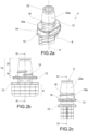
- reference sign 1 indicates, as a whole, a thin-walled packaging comprising a flexible pouch 2, a spout 4 and a closure 6 applied to the spout 4 in order to close it.
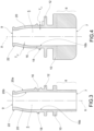
- the spout 4 has an inner spout channel 5 which extends along a spout axis X between an inner opening 7, which is intended to remain inside the pouch 2, and an opposite spout mount 9 from which the product to be consumed comes out.
- the spout 4 comprises a connecting portion 8, usually defined as a "welding boat,” that is provided with the inner opening 7 and is intended to be sealingly applied between the flexible walls of the pouch 2, for example by means of welding.
- the connecting portion 8 ends with a first spout wall 10, orthogonal to the spout axis X.
- the spout 4 also comprises a second spout wall 12 which is spaced apart from and parallel to the first spout wall 10, and a mouth portion 14 which extends from the second spout wall 12 up to the spout mouth 9.
- the mouth portion 14 preferably comprises a first annular mouth wall 16 which extends for example from the second spout wall 12 and has a cylindrical outer lateral surface 16a, coaxial to the spout axis X, and a thread 18 for screwing the closure 6, which thread projects from the outer lateral surface 16a.
- the first mouth wall 16 preferably has a cylindrical inner lateral surface 16b, coaxial to the spout axis X.
- the outer lateral surface 16a and the inner lateral surface 16b define a thickness Ts1 of the first mouth wall 16.
- the mouth portion 14 also comprises a second annular mouth wall 20 which extends from the first mouth wall 16 toward the mouth 9.
- the second mouth wall 20 has a domed outer lateral surface 20a, i.e. which has a profile that is at least partially arcuate in cross section, so as to provide a tapered shape.
- the second mouth wall 20 preferably has a domed inner lateral surface 20b which follows the course of the outer lateral surface.
- the spout channel 5 therefore narrows from the inner opening 7 toward the mouth 9, in close proximity to the mouth 9.
- the outer lateral surface 20a and the inner lateral surface 20b define a thickness Ts2 of the second mouth wall 20.
- the thickness Ts2 is preferably constant over the entire second mouth wall 20.
- the spout 4 preferably comprises an annular rib 22 which delimits the mouth 9, has a thickness greater than the thickness Ts of the mouth portion 14, and projects with respect to the outer lateral surface 20a of the second mouth wall 20.
- the closure 6, which is made in a single piece, for example by means of injection molding, from plastics material, is made separately from the spout 4 and may be applied thereto in an irremovable manner.
- the closure 6 comprises a base body 30 comprising an annular inner portion 32, for example in the form of a circular crown, that is provided with an axially extending base hole 34 through which the mouth portion 14 of the spout 4 passes; the base hole 34 is preferably coaxial to the spout axis X and the mouth portion 14 of the spout 4 projects axially beyond an upper face 32a of the inner portion 32.
- the base hole 34 is annularly delimited by a hole wall 36 projecting axially on the opposite side to the upper face 32a of the inner portion 32.
- the base hole 36 is internally provided with threading 38 for screwing the closure 6 to the spout 4, and in particular to the threading 18 of the mouth portion 14.
- the hole wall 36 axially ends with a wall edge 40 provided with at least one tooth 42 adapted to snap-fit engage a relevant projection 44 provided on the spout 4 in an irremovable manner (unless the structure is damaged).
- said projections 44 of the spout 4 are located in the mouth portion 14, adjacent to the threading 18, for example projecting from the second spout wall 12.
- the base body 30 of the closure 6 also comprises an outer portion 50 which, for example, radially externally surrounds the inner portion 32.
- the outer portion 50 comprises a base band 52 that is spaced radially from the inner portion 32 and is connected thereto by a plurality of angularly spaced spokes 54, so as to create spaces 56 extending axially between the inner portion 32 and said base band 52.
- the outer portion 50 also comprises an abutment wall 58 which is placed along the base band 52 and has a front face 58a which is concave outwards.
- the abutment wall 58 is preferably connected to the inner portion 32 by one of said spokes 54.
- the outer portion 50 comprises a guarantee wall 60 which is placed along the base band 52 at the abutment wall 58 and has an outer face 60a inscribed in an imaginary cylindrical surface that is convex outwards.
- the guarantee wall 60 is irreversibly yielding - of course unless subjected to external actions - i.e. it maintains the deformed shape when it is deformed so as to abut against the front face 58a of the abutment wall 58 that is placed behind the guarantee wall 60.
- said guarantee wall 60 is yielding by virtue of the outer face 60a having a saw-tooth shape created by a plurality of steps circumferentially placed side by side.
- the closure 6 also comprises a cap assembly 70 and a flexible hinge 72 that connects the cap assembly 70 to the base body 30 such that the cap assembly 70 may be rotated in order to open and close the closure 6.
- the hinge 72 connects the cap assembly 70 to the band 52 of the outer portion 50 and extends along a hinge axis Y lying on an imaginary plane orthogonal to the spout axis X and tangential to the band 52, so that the cap assembly 70 is rotatable with respect to said hinge axis Y.
- the cap assembly 70 comprises a cap 74, a guarantee portion 76 and preferably a grip portion 78.
- the cap 74 comprises an annular cap wall 80 and a cap base 82 which, in a closed configuration of the closure 6, closes the spout mouth 9 by adhering, for example, to the rib 22.
- the cap wall 80 has a central cap axis Z which, in a closed configuration of the closure 6, coincides with the spout axis X of the spout 4; in this configuration, the cap wall 80 surrounds the second mouth wall 20 of the mouth portion 14.
- the guarantee portion 76 comprises an annular guarantee band 84 which extends radially externally to the cap 74 and which, in the closed configuration of the closure 6, is overlapped by and preferably axially spaced apart from the base band 52 of the base body 30.
- the hinge 72 preferably connects the guarantee band 84 to the base band 52.
- the guarantee band 84 comprises a guarantee tab 86 which, in the closed configuration of the closure 6, axially surmounts the guarantee wall 60 of the base body 30; moreover, the guarantee tab 86 is peripherally delimited by a strip edge 86a which, in the closed configuration, is positioned radially inside the imaginary cylindrical surface on which the outer face 60a of the guarantee wall 60 is inscribable.
- the guarantee tab 86 and the guarantee wall 60 are joined by at least one breakable bridge 88; when the closure 6 is first opened, when the guarantee wall 60 is pressed against the front face 58a of the abutment wall 58, the bridges 88 break and the cap assembly 70 may be rotated in order to open the closure 6.
- the grip portion 78 surrounds the cap 74 and surmounts the guarantee band 84; said grip portion 78 preferably comprises a domed grip region 90 and a guarantee region 92 which forms a recess with respect to the outer surface of the grip region 90 and is placed at the guarantee tab 86.
- the cap 74 is preferably connected to the guarantee band 84 and to the grip portion 78 by a plurality of angularly spaced cap spokes 96, so as to form cap spaces 98 between the cap 74 and the guarantee band 84 and the grip portion 78.
- the base spaces 56 and the cap spaces 98 have an anti-suffocation function.
- the cap assembly 70 surmounts the base body 30, and the cap 74 closes the spout mouth 9 of the spout 4; moreover, in the intact closed configuration, the guarantee band 84 of the cap assembly 70 is joined to the guarantee wall 60 of the base body 30 by the bridges 88, which are integral. Moreover, the strip edge 86a is positioned radially inside the imaginary cylindrical surface on which the outer face 60a of the guarantee wall 60 is inscribed.
- the guarantee wall 60 of the base body 30 is pressed, for example by a finger of the user, such that it abuts against the front face 58a of the abutment wall 58 and deforms permanently.
- the strip edge 86a is thus positioned at least in part radially externally to the deformed guarantee wall 60 and may be used as a contact against the finger of the user in order to raise the cap assembly 70 and break the bridges 88.
- the cap assembly 70 In the open configuration, the cap assembly 70 is rotated with respect to the position assumed in the closed configuration and the hinge 72 is configured to keep the cap assembly 70 sufficiently far away from the spout mouth 9, in order to allow the spout to be used comfortably.
- the closure 6 is made in a single piece, for example
- the closure according to this invention satisfies the above-mentioned requirements, in that it has a guarantee seal that shows that the closure is broken and, once the closure is open, the cap assembly remains connected to the base body which is in turn connected to the spout. It is therefore not possible to separate the cap assembly from the spout and from the pouch, so that all of the components of the packaging have to be disposed of together.
Landscapes
- Engineering & Computer Science (AREA)
- Mechanical Engineering (AREA)
- Closures For Containers (AREA)
- Cartons (AREA)
Claims (10)
- Verschluss (6) für eine Tülle (4) einer flexiblen, dünnwandigen Verpackung (1), umfassend- einen Basiskörper (30), der unlösbar mit der Tülle (4) verschraubt ist, umfassend eine irreversibel nachgebende Garantiewand (60);- eine Kappenanordnung (70), umfassend eine Kappe (74) und eine Garantielasche (86), die in einer geschlossenen Konfiguration die Garantiewand (60) axial überragt;- mindestens eine zerreißbare Brücke (88), die in einer intakten, geschlossenen Konfiguration einstückig ausgebildet ist und die Garantielasche mit der Garantiewand (60) zusammenfügt;- ein flexibles Scharnier (72), das den Basiskörper (30) mit der Kappenanordnung (70) zusammenfügt, um die Kappenanordnung (70) aus der geschlossenen Konfiguration in eine offene Konfiguration zu drehen, in der die Kappe von der Tülleöffnung (9) gelöst ist.
- Verschluss nach Anspruch 1, wobei der Basiskörper (30) mit einem Basisloch (34) zum Einsetzen eines Öffnungsabschnitts (14) der Tülle (4) versehen ist, wobei das Basisloch (34) ringförmig durch eine Lochwand (36) begrenzt ist, die im Inneren mit einem Gewinde (38) zum Verschrauben des Verschlusses (6) mit der Tülle (4) versehen ist.
- Verschluss nach Anspruch 2, wobei die Lochwand (36) axial mit einer Wandkante (40) abschließt, die mit zumindest einem Zahn (42) versehen ist, der so angepasst ist, dass er in einen entsprechenden Vorsprung (44) der Tülle (4) unlösbar eingeschnappt.
- Verschluss nach einem der vorstehenden Ansprüche, wobei der Basiskörper (30) eine Anschlagwand (58) mit einer Vorderseite (58a) umfasst, die nach außen konkav ist, wobei die Garantiewand (60) an der Anschlagwand (58) angeordnet ist, die sich radial außerhalb von dieser befindet.
- Verschluss nach einem der vorstehenden Ansprüche, wobei die Garantiewand (60) eine Außenseite (60a) mit einer Sägezahnform aufweist, die durch eine Vielzahl von Absätzen erzeugt wird, die in Umfangsrichtung nebeneinander angeordnet sind, die ein irreversibles Nachgeben bereitstellen.
- Verschluss nach einem der vorstehenden Ansprüche, wobei sich das Scharnier (72) entlang einer Scharnierachse (Y) erstreckt, die auf einer imaginären Ebene orthogonal zur Kappenachse (Z) in der geschlossenen Konfiguration liegt, so dass die Kappenanordnung (70) in Bezug auf die Scharnierachse (Y) drehbar ist.
- Verschluss nach einem der vorstehenden Ansprüche, wobei die Garantielasche (86) peripher durch eine Laschenkante (86a) begrenzt ist, die in der geschlossenen Konfiguration radial innerhalb einer imaginären zylindrischen Fläche angeordnet ist, auf der eine Außenseite (60a) der Garantiewand (60) beschriftbar ist.
- Verschluss nach einem der vorstehenden Ansprüche, wobei die Kappenanordnung (70) einen Griffabschnitt (78) umfasst, der die Kappe (74) umgibt und einen Griffbereich (90) und einen Garantiebereich (92) umfasst, der eine Aussparung in Bezug auf eine Außenfläche des Griffbereichs (90) bildet, wobei der Garantiebereich (92) an der Garantielasche (86) angeordnet ist.
- Verschlussanordnung, umfassend:- eine Tülle (4), die mit einem Öffnungsabschnitt (14) versehen ist, umfassend eine erste Öffnungswand (16), die außen ein Gewinde (18) aufweist, und eine zweite Öffnungswand (20) mit einer äußeren Seitenfläche (20a), die keine Vorsprünge aufweist;- einen Verschluss (6) nach einem der vorstehenden Ansprüche, wobei der Basiskörper (30) mit der ersten Öffnungswand (16) irreversibel verschraubt ist und die zweite Öffnungswand (20) den Basiskörper (30) durchläuft und axial von diesem vorsteht.
- Verschlussanordnung nach Anspruch 9, wobei die Tülle (4) zumindest einen Vorsprung (44) zum irreversiblen Einschnappen in den Basiskörper (30) des Verschlusses (6) umfasst.
Applications Claiming Priority (2)
| Application Number | Priority Date | Filing Date | Title |
|---|---|---|---|
| IT102020000017998A IT202000017998A1 (it) | 2020-07-24 | 2020-07-24 | Chiusura per un imballo a parete sottile munito di cannuccia |
| PCT/IB2021/055160 WO2022018536A1 (en) | 2020-07-24 | 2021-06-11 | Closure for a thin-walled packaging provided with a spout |
Publications (2)
| Publication Number | Publication Date |
|---|---|
| EP4185539A1 EP4185539A1 (de) | 2023-05-31 |
| EP4185539B1 true EP4185539B1 (de) | 2024-07-24 |
Family
ID=72801902
Family Applications (1)
| Application Number | Title | Priority Date | Filing Date |
|---|---|---|---|
| EP21736698.8A Active EP4185539B1 (de) | 2020-07-24 | 2021-06-11 | Verschluss für eine dünnwandige verpackung mit einem ausgiesser |
Country Status (8)
| Country | Link |
|---|---|
| US (1) | US12214949B2 (de) |
| EP (1) | EP4185539B1 (de) |
| BR (1) | BR112022026826A2 (de) |
| CL (1) | CL2022003758A1 (de) |
| ES (1) | ES2991330T3 (de) |
| IT (1) | IT202000017998A1 (de) |
| MX (1) | MX2023000147A (de) |
| WO (1) | WO2022018536A1 (de) |
Families Citing this family (4)
| Publication number | Priority date | Publication date | Assignee | Title |
|---|---|---|---|---|
| IT202000019939A1 (it) * | 2020-08-11 | 2022-02-11 | Guala Pack Spa | Chiusura per una cannuccia di un imballo a pareti sottili |
| CH719432B1 (de) * | 2022-02-16 | 2024-11-29 | Alpla Werke Alwin Lehner Gmbh & Co Kg | Klappverschluss aus Kunststoff zum Verschliessen eines Behälters. |
| PL245194B1 (pl) * | 2022-06-27 | 2024-05-27 | Kamil Krajewski | Dozownik do płynnych produktów w saszetkach |
| GB202218192D0 (en) * | 2022-12-02 | 2023-01-18 | Rpc Bramlage Gmbh | Closure |
Family Cites Families (12)
| Publication number | Priority date | Publication date | Assignee | Title |
|---|---|---|---|---|
| DK1247749T4 (da) * | 1999-05-04 | 2007-09-03 | Astepo Srl | Emballagepose |
| FR2824812B1 (fr) * | 2001-05-16 | 2003-09-19 | Oreal | Capsule de distribution avec ouverture securisee |
| ES2262450B1 (es) * | 2006-05-18 | 2007-09-16 | Seaplast, S.A. | "tapon con tapa abatible para botellas y similares dotado de un sistema automatico de apertura de la tapa que comprende un pulsador mejorado". |
| PL2588384T3 (pl) | 2011-03-03 | 2014-10-31 | Aptargroup Inc | Zamknięcie z elementem zabezpieczającym |
| US10322856B2 (en) * | 2013-06-04 | 2019-06-18 | Csp Technologies, Inc. | Container having a child resistant closure with a small profile |
| US9968516B2 (en) * | 2014-11-06 | 2018-05-15 | Creative Mechanisms, Inc. | Closure with sequenced double release |
| US10440294B1 (en) | 2018-09-05 | 2019-10-08 | Google Llc | Compact color and depth imaging system |
| US11993867B2 (en) | 2018-09-12 | 2024-05-28 | Gharda Chemicals Limited | Spun ABPBI fibers and process for preparing the same |
| IT201800009967A1 (it) | 2018-10-31 | 2020-05-01 | Guala Pack Spa | Chiusura per cannuccia di un imballo flessibile a pareti sottili |
| NL2022097B1 (en) * | 2018-11-29 | 2020-06-26 | Scholle Ipn Ip Bv | A spouted pouch provided with a closure device |
| IT201900001829A1 (it) | 2019-02-08 | 2020-08-08 | Guala Pack Spa | Chiusura per cannuccia di un imballo flessibile a pareti sottili |
| IT201900007497A1 (it) | 2019-05-29 | 2020-11-29 | Guala Pack Spa | Chiusura per una cannuccia per imballi flessibili a pareti sottili |
-
2020
- 2020-07-24 IT IT102020000017998A patent/IT202000017998A1/it unknown
-
2021
- 2021-06-11 EP EP21736698.8A patent/EP4185539B1/de active Active
- 2021-06-11 ES ES21736698T patent/ES2991330T3/es active Active
- 2021-06-11 MX MX2023000147A patent/MX2023000147A/es unknown
- 2021-06-11 US US18/003,726 patent/US12214949B2/en active Active
- 2021-06-11 WO PCT/IB2021/055160 patent/WO2022018536A1/en not_active Ceased
- 2021-06-11 BR BR112022026826A patent/BR112022026826A2/pt unknown
-
2022
- 2022-12-26 CL CL2022003758A patent/CL2022003758A1/es unknown
Also Published As
| Publication number | Publication date |
|---|---|
| IT202000017998A1 (it) | 2022-01-24 |
| BR112022026826A2 (pt) | 2023-01-31 |
| WO2022018536A1 (en) | 2022-01-27 |
| ES2991330T3 (es) | 2024-12-03 |
| EP4185539A1 (de) | 2023-05-31 |
| US12214949B2 (en) | 2025-02-04 |
| CL2022003758A1 (es) | 2023-05-19 |
| US20230257180A1 (en) | 2023-08-17 |
| MX2023000147A (es) | 2023-02-22 |
Similar Documents
| Publication | Publication Date | Title |
|---|---|---|
| EP4185539B1 (de) | Verschluss für eine dünnwandige verpackung mit einem ausgiesser | |
| AU2017304110B2 (en) | Closure with tamper-evident band | |
| CN105008236B (zh) | 封盖或与封盖相关的改进 | |
| US5215204A (en) | Tamper evident closure with hinged band | |
| US6321924B1 (en) | Resealable pushable container closure and cover therefor | |
| US4709823A (en) | Tamper evident bottle or package closure | |
| US20020088813A1 (en) | Product dispensing closure with lid support | |
| US12195258B2 (en) | Tamper-evident pouch closure | |
| US11072473B2 (en) | Flip-top tube with tamper-evident seal | |
| EP4196409B1 (de) | Verschluss für einen ausguss in einer dünnwandigen verpackung | |
| EP4139224B1 (de) | Verschlussanordnung für einen dünnwandigen verpackungsbeutel | |
| EP4267483B1 (de) | Verschluss für einen strohhalm einer dünnwandigen flexiblen verpackung | |
| KR100985326B1 (ko) | 개봉 흔적이 남는 밀봉장치를 구비한 액체용기용 클로저 | |
| RU2823610C1 (ru) | Укупорочное средство для тонкостенной упаковки с горлышком | |
| WO2023012663A1 (en) | Closure for a spout of a thin-walled package | |
| US6568548B1 (en) | Closure with tamper-indicating band | |
| US20240425222A1 (en) | Closure for a spout of a flexible thin-walled packaging | |
| WO2015022518A1 (en) | Closure assembly | |
| IT202000018001A1 (it) | Cannuccia per un imballo a parete sottile | |
| JP2005178905A (ja) | プラスチック製押外しキャップ |
Legal Events
| Date | Code | Title | Description |
|---|---|---|---|
| STAA | Information on the status of an ep patent application or granted ep patent |
Free format text: STATUS: UNKNOWN |
|
| STAA | Information on the status of an ep patent application or granted ep patent |
Free format text: STATUS: THE INTERNATIONAL PUBLICATION HAS BEEN MADE |
|
| PUAI | Public reference made under article 153(3) epc to a published international application that has entered the european phase |
Free format text: ORIGINAL CODE: 0009012 |
|
| STAA | Information on the status of an ep patent application or granted ep patent |
Free format text: STATUS: REQUEST FOR EXAMINATION WAS MADE |
|
| 17P | Request for examination filed |
Effective date: 20221202 |
|
| AK | Designated contracting states |
Kind code of ref document: A1 Designated state(s): AL AT BE BG CH CY CZ DE DK EE ES FI FR GB GR HR HU IE IS IT LI LT LU LV MC MK MT NL NO PL PT RO RS SE SI SK SM TR |
|
| TPAC | Observations filed by third parties |
Free format text: ORIGINAL CODE: EPIDOSNTIPA |
|
| P01 | Opt-out of the competence of the unified patent court (upc) registered |
Effective date: 20230714 |
|
| DAV | Request for validation of the european patent (deleted) | ||
| DAX | Request for extension of the european patent (deleted) | ||
| GRAP | Despatch of communication of intention to grant a patent |
Free format text: ORIGINAL CODE: EPIDOSNIGR1 |
|
| STAA | Information on the status of an ep patent application or granted ep patent |
Free format text: STATUS: GRANT OF PATENT IS INTENDED |
|
| INTG | Intention to grant announced |
Effective date: 20240221 |
|
| GRAS | Grant fee paid |
Free format text: ORIGINAL CODE: EPIDOSNIGR3 |
|
| GRAA | (expected) grant |
Free format text: ORIGINAL CODE: 0009210 |
|
| STAA | Information on the status of an ep patent application or granted ep patent |
Free format text: STATUS: THE PATENT HAS BEEN GRANTED |
|
| AK | Designated contracting states |
Kind code of ref document: B1 Designated state(s): AL AT BE BG CH CY CZ DE DK EE ES FI FR GB GR HR HU IE IS IT LI LT LU LV MC MK MT NL NO PL PT RO RS SE SI SK SM TR |
|
| REG | Reference to a national code |
Ref country code: GB Ref legal event code: FG4D |
|
| REG | Reference to a national code |
Ref country code: CH Ref legal event code: EP |
|
| REG | Reference to a national code |
Ref country code: IE Ref legal event code: FG4D Ref country code: DE Ref legal event code: R096 Ref document number: 602021016179 Country of ref document: DE |
|
| REG | Reference to a national code |
Ref country code: LT Ref legal event code: MG9D |
|
| REG | Reference to a national code |
Ref country code: NL Ref legal event code: MP Effective date: 20240724 |
|
| REG | Reference to a national code |
Ref country code: ES Ref legal event code: FG2A Ref document number: 2991330 Country of ref document: ES Kind code of ref document: T3 Effective date: 20241203 |
|
| PG25 | Lapsed in a contracting state [announced via postgrant information from national office to epo] |
Ref country code: PT Free format text: LAPSE BECAUSE OF FAILURE TO SUBMIT A TRANSLATION OF THE DESCRIPTION OR TO PAY THE FEE WITHIN THE PRESCRIBED TIME-LIMIT Effective date: 20241125 |
|
| REG | Reference to a national code |
Ref country code: AT Ref legal event code: MK05 Ref document number: 1706122 Country of ref document: AT Kind code of ref document: T Effective date: 20240724 |
|
| PG25 | Lapsed in a contracting state [announced via postgrant information from national office to epo] |
Ref country code: NL Free format text: LAPSE BECAUSE OF FAILURE TO SUBMIT A TRANSLATION OF THE DESCRIPTION OR TO PAY THE FEE WITHIN THE PRESCRIBED TIME-LIMIT Effective date: 20240724 |
|
| PG25 | Lapsed in a contracting state [announced via postgrant information from national office to epo] |
Ref country code: PT Free format text: LAPSE BECAUSE OF FAILURE TO SUBMIT A TRANSLATION OF THE DESCRIPTION OR TO PAY THE FEE WITHIN THE PRESCRIBED TIME-LIMIT Effective date: 20241125 Ref country code: NL Free format text: LAPSE BECAUSE OF FAILURE TO SUBMIT A TRANSLATION OF THE DESCRIPTION OR TO PAY THE FEE WITHIN THE PRESCRIBED TIME-LIMIT Effective date: 20240724 |
|
| PG25 | Lapsed in a contracting state [announced via postgrant information from national office to epo] |
Ref country code: NO Free format text: LAPSE BECAUSE OF FAILURE TO SUBMIT A TRANSLATION OF THE DESCRIPTION OR TO PAY THE FEE WITHIN THE PRESCRIBED TIME-LIMIT Effective date: 20241024 |
|
| PG25 | Lapsed in a contracting state [announced via postgrant information from national office to epo] |
Ref country code: PL Free format text: LAPSE BECAUSE OF FAILURE TO SUBMIT A TRANSLATION OF THE DESCRIPTION OR TO PAY THE FEE WITHIN THE PRESCRIBED TIME-LIMIT Effective date: 20240724 Ref country code: GR Free format text: LAPSE BECAUSE OF FAILURE TO SUBMIT A TRANSLATION OF THE DESCRIPTION OR TO PAY THE FEE WITHIN THE PRESCRIBED TIME-LIMIT Effective date: 20241025 Ref country code: FI Free format text: LAPSE BECAUSE OF FAILURE TO SUBMIT A TRANSLATION OF THE DESCRIPTION OR TO PAY THE FEE WITHIN THE PRESCRIBED TIME-LIMIT Effective date: 20240724 |
|
| PG25 | Lapsed in a contracting state [announced via postgrant information from national office to epo] |
Ref country code: BG Free format text: LAPSE BECAUSE OF FAILURE TO SUBMIT A TRANSLATION OF THE DESCRIPTION OR TO PAY THE FEE WITHIN THE PRESCRIBED TIME-LIMIT Effective date: 20240724 |
|
| PG25 | Lapsed in a contracting state [announced via postgrant information from national office to epo] |
Ref country code: LV Free format text: LAPSE BECAUSE OF FAILURE TO SUBMIT A TRANSLATION OF THE DESCRIPTION OR TO PAY THE FEE WITHIN THE PRESCRIBED TIME-LIMIT Effective date: 20240724 |
|
| PG25 | Lapsed in a contracting state [announced via postgrant information from national office to epo] |
Ref country code: IS Free format text: LAPSE BECAUSE OF FAILURE TO SUBMIT A TRANSLATION OF THE DESCRIPTION OR TO PAY THE FEE WITHIN THE PRESCRIBED TIME-LIMIT Effective date: 20241124 Ref country code: AT Free format text: LAPSE BECAUSE OF FAILURE TO SUBMIT A TRANSLATION OF THE DESCRIPTION OR TO PAY THE FEE WITHIN THE PRESCRIBED TIME-LIMIT Effective date: 20240724 |
|
| PG25 | Lapsed in a contracting state [announced via postgrant information from national office to epo] |
Ref country code: HR Free format text: LAPSE BECAUSE OF FAILURE TO SUBMIT A TRANSLATION OF THE DESCRIPTION OR TO PAY THE FEE WITHIN THE PRESCRIBED TIME-LIMIT Effective date: 20240724 |
|
| PG25 | Lapsed in a contracting state [announced via postgrant information from national office to epo] |
Ref country code: RS Free format text: LAPSE BECAUSE OF FAILURE TO SUBMIT A TRANSLATION OF THE DESCRIPTION OR TO PAY THE FEE WITHIN THE PRESCRIBED TIME-LIMIT Effective date: 20241024 |
|
| PG25 | Lapsed in a contracting state [announced via postgrant information from national office to epo] |
Ref country code: RS Free format text: LAPSE BECAUSE OF FAILURE TO SUBMIT A TRANSLATION OF THE DESCRIPTION OR TO PAY THE FEE WITHIN THE PRESCRIBED TIME-LIMIT Effective date: 20241024 Ref country code: PL Free format text: LAPSE BECAUSE OF FAILURE TO SUBMIT A TRANSLATION OF THE DESCRIPTION OR TO PAY THE FEE WITHIN THE PRESCRIBED TIME-LIMIT Effective date: 20240724 Ref country code: NO Free format text: LAPSE BECAUSE OF FAILURE TO SUBMIT A TRANSLATION OF THE DESCRIPTION OR TO PAY THE FEE WITHIN THE PRESCRIBED TIME-LIMIT Effective date: 20241024 Ref country code: LV Free format text: LAPSE BECAUSE OF FAILURE TO SUBMIT A TRANSLATION OF THE DESCRIPTION OR TO PAY THE FEE WITHIN THE PRESCRIBED TIME-LIMIT Effective date: 20240724 Ref country code: IS Free format text: LAPSE BECAUSE OF FAILURE TO SUBMIT A TRANSLATION OF THE DESCRIPTION OR TO PAY THE FEE WITHIN THE PRESCRIBED TIME-LIMIT Effective date: 20241124 Ref country code: HR Free format text: LAPSE BECAUSE OF FAILURE TO SUBMIT A TRANSLATION OF THE DESCRIPTION OR TO PAY THE FEE WITHIN THE PRESCRIBED TIME-LIMIT Effective date: 20240724 Ref country code: GR Free format text: LAPSE BECAUSE OF FAILURE TO SUBMIT A TRANSLATION OF THE DESCRIPTION OR TO PAY THE FEE WITHIN THE PRESCRIBED TIME-LIMIT Effective date: 20241025 Ref country code: FI Free format text: LAPSE BECAUSE OF FAILURE TO SUBMIT A TRANSLATION OF THE DESCRIPTION OR TO PAY THE FEE WITHIN THE PRESCRIBED TIME-LIMIT Effective date: 20240724 Ref country code: BG Free format text: LAPSE BECAUSE OF FAILURE TO SUBMIT A TRANSLATION OF THE DESCRIPTION OR TO PAY THE FEE WITHIN THE PRESCRIBED TIME-LIMIT Effective date: 20240724 Ref country code: AT Free format text: LAPSE BECAUSE OF FAILURE TO SUBMIT A TRANSLATION OF THE DESCRIPTION OR TO PAY THE FEE WITHIN THE PRESCRIBED TIME-LIMIT Effective date: 20240724 |
|
| PG25 | Lapsed in a contracting state [announced via postgrant information from national office to epo] |
Ref country code: RO Free format text: LAPSE BECAUSE OF FAILURE TO SUBMIT A TRANSLATION OF THE DESCRIPTION OR TO PAY THE FEE WITHIN THE PRESCRIBED TIME-LIMIT Effective date: 20240724 Ref country code: DK Free format text: LAPSE BECAUSE OF FAILURE TO SUBMIT A TRANSLATION OF THE DESCRIPTION OR TO PAY THE FEE WITHIN THE PRESCRIBED TIME-LIMIT Effective date: 20240724 Ref country code: SM Free format text: LAPSE BECAUSE OF FAILURE TO SUBMIT A TRANSLATION OF THE DESCRIPTION OR TO PAY THE FEE WITHIN THE PRESCRIBED TIME-LIMIT Effective date: 20240724 |
|
| PG25 | Lapsed in a contracting state [announced via postgrant information from national office to epo] |
Ref country code: EE Free format text: LAPSE BECAUSE OF FAILURE TO SUBMIT A TRANSLATION OF THE DESCRIPTION OR TO PAY THE FEE WITHIN THE PRESCRIBED TIME-LIMIT Effective date: 20240724 |
|
| PG25 | Lapsed in a contracting state [announced via postgrant information from national office to epo] |
Ref country code: CZ Free format text: LAPSE BECAUSE OF FAILURE TO SUBMIT A TRANSLATION OF THE DESCRIPTION OR TO PAY THE FEE WITHIN THE PRESCRIBED TIME-LIMIT Effective date: 20240724 |
|
| REG | Reference to a national code |
Ref country code: DE Ref legal event code: R097 Ref document number: 602021016179 Country of ref document: DE |
|
| PG25 | Lapsed in a contracting state [announced via postgrant information from national office to epo] |
Ref country code: SK Free format text: LAPSE BECAUSE OF FAILURE TO SUBMIT A TRANSLATION OF THE DESCRIPTION OR TO PAY THE FEE WITHIN THE PRESCRIBED TIME-LIMIT Effective date: 20240724 |
|
| PLBE | No opposition filed within time limit |
Free format text: ORIGINAL CODE: 0009261 |
|
| STAA | Information on the status of an ep patent application or granted ep patent |
Free format text: STATUS: NO OPPOSITION FILED WITHIN TIME LIMIT |
|
| 26N | No opposition filed |
Effective date: 20250425 |
|
| PGFP | Annual fee paid to national office [announced via postgrant information from national office to epo] |
Ref country code: DE Payment date: 20250624 Year of fee payment: 5 |
|
| PGFP | Annual fee paid to national office [announced via postgrant information from national office to epo] |
Ref country code: GB Payment date: 20250618 Year of fee payment: 5 |
|
| PGFP | Annual fee paid to national office [announced via postgrant information from national office to epo] |
Ref country code: IT Payment date: 20250526 Year of fee payment: 5 |
|
| PGFP | Annual fee paid to national office [announced via postgrant information from national office to epo] |
Ref country code: FR Payment date: 20250530 Year of fee payment: 5 |
|
| PG25 | Lapsed in a contracting state [announced via postgrant information from national office to epo] |
Ref country code: SE Free format text: LAPSE BECAUSE OF FAILURE TO SUBMIT A TRANSLATION OF THE DESCRIPTION OR TO PAY THE FEE WITHIN THE PRESCRIBED TIME-LIMIT Effective date: 20240724 |
|
| PGFP | Annual fee paid to national office [announced via postgrant information from national office to epo] |
Ref country code: ES Payment date: 20250701 Year of fee payment: 5 |
|
| REG | Reference to a national code |
Ref country code: CH Ref legal event code: H13 Free format text: ST27 STATUS EVENT CODE: U-0-0-H10-H13 (AS PROVIDED BY THE NATIONAL OFFICE) Effective date: 20260127 |
|
| PG25 | Lapsed in a contracting state [announced via postgrant information from national office to epo] |
Ref country code: MC Free format text: LAPSE BECAUSE OF FAILURE TO SUBMIT A TRANSLATION OF THE DESCRIPTION OR TO PAY THE FEE WITHIN THE PRESCRIBED TIME-LIMIT Effective date: 20240724 |
|
| PG25 | Lapsed in a contracting state [announced via postgrant information from national office to epo] |
Ref country code: LU Free format text: LAPSE BECAUSE OF NON-PAYMENT OF DUE FEES Effective date: 20250611 |
|
| REG | Reference to a national code |
Ref country code: BE Ref legal event code: MM Effective date: 20250630 |
|
| PG25 | Lapsed in a contracting state [announced via postgrant information from national office to epo] |
Ref country code: IE Free format text: LAPSE BECAUSE OF NON-PAYMENT OF DUE FEES Effective date: 20250611 |
|
| PG25 | Lapsed in a contracting state [announced via postgrant information from national office to epo] |
Ref country code: BE Free format text: LAPSE BECAUSE OF NON-PAYMENT OF DUE FEES Effective date: 20250630 |
|
| PG25 | Lapsed in a contracting state [announced via postgrant information from national office to epo] |
Ref country code: CH Free format text: LAPSE BECAUSE OF NON-PAYMENT OF DUE FEES Effective date: 20250630 |