EP4184722A1 - Elektrischer verbindungsstecker zum verbinden einer flexiblen gedruckten schaltung mit einem kabelbaum - Google Patents
Elektrischer verbindungsstecker zum verbinden einer flexiblen gedruckten schaltung mit einem kabelbaum Download PDFInfo
- Publication number
- EP4184722A1 EP4184722A1 EP21208665.6A EP21208665A EP4184722A1 EP 4184722 A1 EP4184722 A1 EP 4184722A1 EP 21208665 A EP21208665 A EP 21208665A EP 4184722 A1 EP4184722 A1 EP 4184722A1
- Authority
- EP
- European Patent Office
- Prior art keywords
- connector
- terminal
- layer
- electrically insulated
- printed electronic
- Prior art date
- Legal status (The legal status is an assumption and is not a legal conclusion. Google has not performed a legal analysis and makes no representation as to the accuracy of the status listed.)
- Pending
Links
- 239000010410 layer Substances 0.000 claims abstract description 78
- 239000002346 layers by function Substances 0.000 claims abstract description 24
- 239000000976 ink Substances 0.000 claims abstract description 8
- 239000000463 material Substances 0.000 claims abstract description 4
- 238000004519 manufacturing process Methods 0.000 claims description 7
- 238000000465 moulding Methods 0.000 claims description 7
- 238000005476 soldering Methods 0.000 claims description 6
- 239000000088 plastic resin Substances 0.000 claims description 3
- 239000000919 ceramic Substances 0.000 claims description 2
- 238000002788 crimping Methods 0.000 claims description 2
- 239000011888 foil Substances 0.000 claims description 2
- 229920000642 polymer Polymers 0.000 claims description 2
- 230000013011 mating Effects 0.000 description 10
- 230000008901 benefit Effects 0.000 description 3
- 230000010287 polarization Effects 0.000 description 3
- 230000008878 coupling Effects 0.000 description 2
- 238000010168 coupling process Methods 0.000 description 2
- 238000005859 coupling reaction Methods 0.000 description 2
- 230000007246 mechanism Effects 0.000 description 2
- 238000004088 simulation Methods 0.000 description 2
- 239000000758 substrate Substances 0.000 description 2
- OKTJSMMVPCPJKN-UHFFFAOYSA-N Carbon Chemical compound [C] OKTJSMMVPCPJKN-UHFFFAOYSA-N 0.000 description 1
- RYGMFSIKBFXOCR-UHFFFAOYSA-N Copper Chemical compound [Cu] RYGMFSIKBFXOCR-UHFFFAOYSA-N 0.000 description 1
- BQCADISMDOOEFD-UHFFFAOYSA-N Silver Chemical compound [Ag] BQCADISMDOOEFD-UHFFFAOYSA-N 0.000 description 1
- 229910052799 carbon Inorganic materials 0.000 description 1
- 239000011889 copper foil Substances 0.000 description 1
- 230000001419 dependent effect Effects 0.000 description 1
- 238000001746 injection moulding Methods 0.000 description 1
- 238000000034 method Methods 0.000 description 1
- 230000008569 process Effects 0.000 description 1
- 239000011347 resin Substances 0.000 description 1
- 229920005989 resin Polymers 0.000 description 1
- 229910052709 silver Inorganic materials 0.000 description 1
- 239000004332 silver Substances 0.000 description 1
- 239000000243 solution Substances 0.000 description 1
Images


Classifications
-
- H—ELECTRICITY
- H01—ELECTRIC ELEMENTS
- H01R—ELECTRICALLY-CONDUCTIVE CONNECTIONS; STRUCTURAL ASSOCIATIONS OF A PLURALITY OF MUTUALLY-INSULATED ELECTRICAL CONNECTING ELEMENTS; COUPLING DEVICES; CURRENT COLLECTORS
- H01R12/00—Structural associations of a plurality of mutually-insulated electrical connecting elements, specially adapted for printed circuits, e.g. printed circuit boards [PCB], flat or ribbon cables, or like generally planar structures, e.g. terminal strips, terminal blocks; Coupling devices specially adapted for printed circuits, flat or ribbon cables, or like generally planar structures; Terminals specially adapted for contact with, or insertion into, printed circuits, flat or ribbon cables, or like generally planar structures
- H01R12/70—Coupling devices
- H01R12/77—Coupling devices for flexible printed circuits, flat or ribbon cables or like structures
- H01R12/78—Coupling devices for flexible printed circuits, flat or ribbon cables or like structures connecting to other flexible printed circuits, flat or ribbon cables or like structures
-
- H—ELECTRICITY
- H01—ELECTRIC ELEMENTS
- H01R—ELECTRICALLY-CONDUCTIVE CONNECTIONS; STRUCTURAL ASSOCIATIONS OF A PLURALITY OF MUTUALLY-INSULATED ELECTRICAL CONNECTING ELEMENTS; COUPLING DEVICES; CURRENT COLLECTORS
- H01R12/00—Structural associations of a plurality of mutually-insulated electrical connecting elements, specially adapted for printed circuits, e.g. printed circuit boards [PCB], flat or ribbon cables, or like generally planar structures, e.g. terminal strips, terminal blocks; Coupling devices specially adapted for printed circuits, flat or ribbon cables, or like generally planar structures; Terminals specially adapted for contact with, or insertion into, printed circuits, flat or ribbon cables, or like generally planar structures
- H01R12/50—Fixed connections
- H01R12/59—Fixed connections for flexible printed circuits, flat or ribbon cables or like structures
- H01R12/592—Fixed connections for flexible printed circuits, flat or ribbon cables or like structures connections to contact elements
-
- H—ELECTRICITY
- H01—ELECTRIC ELEMENTS
- H01R—ELECTRICALLY-CONDUCTIVE CONNECTIONS; STRUCTURAL ASSOCIATIONS OF A PLURALITY OF MUTUALLY-INSULATED ELECTRICAL CONNECTING ELEMENTS; COUPLING DEVICES; CURRENT COLLECTORS
- H01R12/00—Structural associations of a plurality of mutually-insulated electrical connecting elements, specially adapted for printed circuits, e.g. printed circuit boards [PCB], flat or ribbon cables, or like generally planar structures, e.g. terminal strips, terminal blocks; Coupling devices specially adapted for printed circuits, flat or ribbon cables, or like generally planar structures; Terminals specially adapted for contact with, or insertion into, printed circuits, flat or ribbon cables, or like generally planar structures
- H01R12/50—Fixed connections
- H01R12/59—Fixed connections for flexible printed circuits, flat or ribbon cables or like structures
- H01R12/65—Fixed connections for flexible printed circuits, flat or ribbon cables or like structures characterised by the terminal
- H01R12/69—Fixed connections for flexible printed circuits, flat or ribbon cables or like structures characterised by the terminal deformable terminals, e.g. crimping terminals
-
- H—ELECTRICITY
- H01—ELECTRIC ELEMENTS
- H01R—ELECTRICALLY-CONDUCTIVE CONNECTIONS; STRUCTURAL ASSOCIATIONS OF A PLURALITY OF MUTUALLY-INSULATED ELECTRICAL CONNECTING ELEMENTS; COUPLING DEVICES; CURRENT COLLECTORS
- H01R12/00—Structural associations of a plurality of mutually-insulated electrical connecting elements, specially adapted for printed circuits, e.g. printed circuit boards [PCB], flat or ribbon cables, or like generally planar structures, e.g. terminal strips, terminal blocks; Coupling devices specially adapted for printed circuits, flat or ribbon cables, or like generally planar structures; Terminals specially adapted for contact with, or insertion into, printed circuits, flat or ribbon cables, or like generally planar structures
- H01R12/70—Coupling devices
- H01R12/77—Coupling devices for flexible printed circuits, flat or ribbon cables or like structures
- H01R12/771—Details
- H01R12/774—Retainers
-
- H—ELECTRICITY
- H01—ELECTRIC ELEMENTS
- H01R—ELECTRICALLY-CONDUCTIVE CONNECTIONS; STRUCTURAL ASSOCIATIONS OF A PLURALITY OF MUTUALLY-INSULATED ELECTRICAL CONNECTING ELEMENTS; COUPLING DEVICES; CURRENT COLLECTORS
- H01R13/00—Details of coupling devices of the kinds covered by groups H01R12/70 or H01R24/00 - H01R33/00
- H01R13/40—Securing contact members in or to a base or case; Insulating of contact members
- H01R13/405—Securing in non-demountable manner, e.g. moulding, riveting
-
- H—ELECTRICITY
- H01—ELECTRIC ELEMENTS
- H01R—ELECTRICALLY-CONDUCTIVE CONNECTIONS; STRUCTURAL ASSOCIATIONS OF A PLURALITY OF MUTUALLY-INSULATED ELECTRICAL CONNECTING ELEMENTS; COUPLING DEVICES; CURRENT COLLECTORS
- H01R4/00—Electrically-conductive connections between two or more conductive members in direct contact, i.e. touching one another; Means for effecting or maintaining such contact; Electrically-conductive connections having two or more spaced connecting locations for conductors and using contact members penetrating insulation
- H01R4/02—Soldered or welded connections
- H01R4/023—Soldered or welded connections between cables or wires and terminals
-
- H—ELECTRICITY
- H01—ELECTRIC ELEMENTS
- H01R—ELECTRICALLY-CONDUCTIVE CONNECTIONS; STRUCTURAL ASSOCIATIONS OF A PLURALITY OF MUTUALLY-INSULATED ELECTRICAL CONNECTING ELEMENTS; COUPLING DEVICES; CURRENT COLLECTORS
- H01R43/00—Apparatus or processes specially adapted for manufacturing, assembling, maintaining, or repairing of line connectors or current collectors or for joining electric conductors
- H01R43/20—Apparatus or processes specially adapted for manufacturing, assembling, maintaining, or repairing of line connectors or current collectors or for joining electric conductors for assembling or disassembling contact members with insulating base, case or sleeve
- H01R43/24—Assembling by moulding on contact members
-
- H—ELECTRICITY
- H05—ELECTRIC TECHNIQUES NOT OTHERWISE PROVIDED FOR
- H05K—PRINTED CIRCUITS; CASINGS OR CONSTRUCTIONAL DETAILS OF ELECTRIC APPARATUS; MANUFACTURE OF ASSEMBLAGES OF ELECTRICAL COMPONENTS
- H05K1/00—Printed circuits
- H05K1/18—Printed circuits structurally associated with non-printed electric components
- H05K1/189—Printed circuits structurally associated with non-printed electric components characterised by the use of a flexible or folded printed circuit
-
- H—ELECTRICITY
- H05—ELECTRIC TECHNIQUES NOT OTHERWISE PROVIDED FOR
- H05K—PRINTED CIRCUITS; CASINGS OR CONSTRUCTIONAL DETAILS OF ELECTRIC APPARATUS; MANUFACTURE OF ASSEMBLAGES OF ELECTRICAL COMPONENTS
- H05K3/00—Apparatus or processes for manufacturing printed circuits
- H05K3/22—Secondary treatment of printed circuits
- H05K3/28—Applying non-metallic protective coatings
- H05K3/281—Applying non-metallic protective coatings by means of a preformed insulating foil
-
- H—ELECTRICITY
- H01—ELECTRIC ELEMENTS
- H01R—ELECTRICALLY-CONDUCTIVE CONNECTIONS; STRUCTURAL ASSOCIATIONS OF A PLURALITY OF MUTUALLY-INSULATED ELECTRICAL CONNECTING ELEMENTS; COUPLING DEVICES; CURRENT COLLECTORS
- H01R13/00—Details of coupling devices of the kinds covered by groups H01R12/70 or H01R24/00 - H01R33/00
- H01R13/62—Means for facilitating engagement or disengagement of coupling parts or for holding them in engagement
- H01R13/627—Snap or like fastening
-
- H—ELECTRICITY
- H05—ELECTRIC TECHNIQUES NOT OTHERWISE PROVIDED FOR
- H05K—PRINTED CIRCUITS; CASINGS OR CONSTRUCTIONAL DETAILS OF ELECTRIC APPARATUS; MANUFACTURE OF ASSEMBLAGES OF ELECTRICAL COMPONENTS
- H05K1/00—Printed circuits
- H05K1/02—Details
- H05K1/11—Printed elements for providing electric connections to or between printed circuits
- H05K1/117—Pads along the edge of rigid circuit boards, e.g. for pluggable connectors
-
- H—ELECTRICITY
- H05—ELECTRIC TECHNIQUES NOT OTHERWISE PROVIDED FOR
- H05K—PRINTED CIRCUITS; CASINGS OR CONSTRUCTIONAL DETAILS OF ELECTRIC APPARATUS; MANUFACTURE OF ASSEMBLAGES OF ELECTRICAL COMPONENTS
- H05K2201/00—Indexing scheme relating to printed circuits covered by H05K1/00
- H05K2201/03—Conductive materials
- H05K2201/0332—Structure of the conductor
- H05K2201/0388—Other aspects of conductors
- H05K2201/0397—Tab
-
- H—ELECTRICITY
- H05—ELECTRIC TECHNIQUES NOT OTHERWISE PROVIDED FOR
- H05K—PRINTED CIRCUITS; CASINGS OR CONSTRUCTIONAL DETAILS OF ELECTRIC APPARATUS; MANUFACTURE OF ASSEMBLAGES OF ELECTRICAL COMPONENTS
- H05K2201/00—Indexing scheme relating to printed circuits covered by H05K1/00
- H05K2201/09—Shape and layout
- H05K2201/09209—Shape and layout details of conductors
- H05K2201/095—Conductive through-holes or vias
- H05K2201/096—Vertically aligned vias, holes or stacked vias
-
- H—ELECTRICITY
- H05—ELECTRIC TECHNIQUES NOT OTHERWISE PROVIDED FOR
- H05K—PRINTED CIRCUITS; CASINGS OR CONSTRUCTIONAL DETAILS OF ELECTRIC APPARATUS; MANUFACTURE OF ASSEMBLAGES OF ELECTRICAL COMPONENTS
- H05K2201/00—Indexing scheme relating to printed circuits covered by H05K1/00
- H05K2201/09—Shape and layout
- H05K2201/09209—Shape and layout details of conductors
- H05K2201/09654—Shape and layout details of conductors covering at least two types of conductors provided for in H05K2201/09218 - H05K2201/095
- H05K2201/09754—Connector integrally incorporated in the printed circuit board [PCB] or in housing
-
- H—ELECTRICITY
- H05—ELECTRIC TECHNIQUES NOT OTHERWISE PROVIDED FOR
- H05K—PRINTED CIRCUITS; CASINGS OR CONSTRUCTIONAL DETAILS OF ELECTRIC APPARATUS; MANUFACTURE OF ASSEMBLAGES OF ELECTRICAL COMPONENTS
- H05K2201/00—Indexing scheme relating to printed circuits covered by H05K1/00
- H05K2201/10—Details of components or other objects attached to or integrated in a printed circuit board
- H05K2201/10007—Types of components
- H05K2201/10189—Non-printed connector
-
- H—ELECTRICITY
- H05—ELECTRIC TECHNIQUES NOT OTHERWISE PROVIDED FOR
- H05K—PRINTED CIRCUITS; CASINGS OR CONSTRUCTIONAL DETAILS OF ELECTRIC APPARATUS; MANUFACTURE OF ASSEMBLAGES OF ELECTRICAL COMPONENTS
- H05K2201/00—Indexing scheme relating to printed circuits covered by H05K1/00
- H05K2201/10—Details of components or other objects attached to or integrated in a printed circuit board
- H05K2201/10227—Other objects, e.g. metallic pieces
- H05K2201/1031—Surface mounted metallic connector elements
-
- H—ELECTRICITY
- H05—ELECTRIC TECHNIQUES NOT OTHERWISE PROVIDED FOR
- H05K—PRINTED CIRCUITS; CASINGS OR CONSTRUCTIONAL DETAILS OF ELECTRIC APPARATUS; MANUFACTURE OF ASSEMBLAGES OF ELECTRICAL COMPONENTS
- H05K2201/00—Indexing scheme relating to printed circuits covered by H05K1/00
- H05K2201/10—Details of components or other objects attached to or integrated in a printed circuit board
- H05K2201/10431—Details of mounted components
- H05K2201/10568—Integral adaptations of a component or an auxiliary PCB for mounting, e.g. integral spacer element
-
- H—ELECTRICITY
- H05—ELECTRIC TECHNIQUES NOT OTHERWISE PROVIDED FOR
- H05K—PRINTED CIRCUITS; CASINGS OR CONSTRUCTIONAL DETAILS OF ELECTRIC APPARATUS; MANUFACTURE OF ASSEMBLAGES OF ELECTRICAL COMPONENTS
- H05K2203/00—Indexing scheme relating to apparatus or processes for manufacturing printed circuits covered by H05K3/00
- H05K2203/13—Moulding and encapsulation; Deposition techniques; Protective layers
- H05K2203/1305—Moulding and encapsulation
- H05K2203/1327—Moulding over PCB locally or completely
-
- H—ELECTRICITY
- H05—ELECTRIC TECHNIQUES NOT OTHERWISE PROVIDED FOR
- H05K—PRINTED CIRCUITS; CASINGS OR CONSTRUCTIONAL DETAILS OF ELECTRIC APPARATUS; MANUFACTURE OF ASSEMBLAGES OF ELECTRICAL COMPONENTS
- H05K3/00—Apparatus or processes for manufacturing printed circuits
- H05K3/30—Assembling printed circuits with electric components, e.g. with resistor
- H05K3/32—Assembling printed circuits with electric components, e.g. with resistor electrically connecting electric components or wires to printed circuits
- H05K3/325—Assembling printed circuits with electric components, e.g. with resistor electrically connecting electric components or wires to printed circuits by abutting or pinching, i.e. without alloying process; mechanical auxiliary parts therefor
-
- H—ELECTRICITY
- H05—ELECTRIC TECHNIQUES NOT OTHERWISE PROVIDED FOR
- H05K—PRINTED CIRCUITS; CASINGS OR CONSTRUCTIONAL DETAILS OF ELECTRIC APPARATUS; MANUFACTURE OF ASSEMBLAGES OF ELECTRICAL COMPONENTS
- H05K3/00—Apparatus or processes for manufacturing printed circuits
- H05K3/30—Assembling printed circuits with electric components, e.g. with resistor
- H05K3/32—Assembling printed circuits with electric components, e.g. with resistor electrically connecting electric components or wires to printed circuits
- H05K3/34—Assembling printed circuits with electric components, e.g. with resistor electrically connecting electric components or wires to printed circuits by soldering
- H05K3/3405—Edge mounted components, e.g. terminals
Definitions
- the present invention relates to an electrical connector and in particular, the present invention relates to an electrical connector for connecting to a flexible printed circuit (FPC) board and a multi-layer interface comprising such an electrical connector for connecting to a cable harness.
- FPC flexible printed circuit
- FPC board connectors are used in electronic devices for establishing electrical connections between different modules.
- a known electrical connector for connecting to an FPC board aims at providing an FPC connector having a compact size and yet being capable to ensure reliable electrical connection with the FPC.
- Such a connector can be made small and thin in order to meet miniaturization requirements for use in compact electronics devices.
- the FPC can be securely fixed to the connector to establish and maintain electrical connection.
- the connector has a housing and contact elements disposed in the housing.
- the housing has a cavity between its top and bottom side.
- Each contact element has an upper contact arm disposed at the top side and a lower contact arm disposed at the bottom side.
- the cavity is to receive the FPC board therein to establish electrical connection with the upper and lower contact arms.
- a pair of locking members is attached to the housing.
- An example for an FPC board connector is a card edge type connector, which has the form of a printed circuit board (PCB) comprising traces leading to the edge of the board.
- PCB printed circuit board
- a known card edge type connector comprises an FPC board with a card terminal and a female connector with a housing.
- the FPC has a portion forming at least a connector part in belt-shape and a wiring pattern of copper foil or the like is formed on an insulating film of PET or the like, and a cover layer of resin covers on top of it.
- the tip part of this FPC is folded back with the insulating film inside, and a plurality of openings are formed on the base end side adjoining the tip part of the cover layer. This plurality of openings functions as connector parts.
- the card terminal of the FPC can be inserted in and electrically connects to a respective female connector and the connection is fixed by a 180° flap and squeeze around a plastic wall.
- FPC board connectors do not provide a simulation of a 1.6 mm PCB thickness to allow standardized card edge connection or a free coupling flat flex cable (FFC) crimp MQS terminal where the size of 0,64 mm 2 and the pitch of 2,54 mm can be downsized and narrowed on demand.
- the known connectors also do not comprise housing designs that provide polarization and coding features to secure a mating only with a specified counterpart, which would be necessary for providing a standardized interface between an FPC board and a common cable harness. Therefore, there is still a need for an FPC board connector which provides an interface to household appliance industry standardized harnesses.
- the present invention relates to a connector system comprising a male connector with a first electrically insulated connector housing, a printed electronic circuitry with a terminal, and a female connector with a second electrically insulated connector housing.
- the printed electronic circuitry is in-molded with a supporting unit and is attached to the first electrically insulated connector housing of the male connector.
- the female connector is adapted to mate with the male connector and to be connected to a cable harness.
- the housing also provides locking, coding and polarization features to mate a defined female connector which is part of an overall appliance harness system.
- the printed electronic circuitry comprises an FPC, or a ceramic flexible circuit.
- the male connector may comprise a portion that is formed as a board with an edge and with traces leading to the edge, the traces being adapted to be plugged into the matching female connector to form a card edge connection.
- the portion that is formed as a board has a thickness of 1.6 mm.
- the advantage of the present invention is to provide a simulation of a 1.6 mm PCB thickness to allow standardized card edge connection or a free coupling FFC MQS 0.64 mm 2 pin connection including a fixation of the FPC board by the housing.
- Another advantage is that the housing design provides polarization and coding features to secure a mating only with a specified counterpart, which is necessary for providing a standardized interface between an FPC board and a common cable harness.
- the present invention provides an interface to household appliance industry standardized harnesses.
- the first electrically insulated connector housing of the male connector comprises a movable latch which interacts with the supporting unit for locking the first electrically insulated connector housing of the male connector at the supporting unit.
- the first electrically insulated connector housing of the male connector is fabricated by over-molding the terminal.
- the terminal of the printed electronic circuitry may be attached to the first electrically insulated connector housing of the male connector by soldering the contacts of the terminal to the contacts of the first electrically insulated connector housing of the male connector.
- the terminal of the printed electronic circuitry is attached to the first electrically insulated connector housing of the male connector by crimping the contacts of the terminal and by inserting the crimps in the first electrically insulated connector housing of the male connector.
- the present invention also relates to a multi-layer interface comprising a connector system according to any of the embodiments described above.
- the multi-layer interface comprises at least one functional layer comprising the printed electronic circuit with a terminal, and at least one electrically insulating layer, which is different from the at least one functional layer and which comprises the electrically insulated connector housing of the male connector.
- the multi-layer interface may additionally comprise a decorative layer comprising film or natural materials, decorative links, and/or conductive and/or dielectric inks.
- Conductive inks can comprise for example silver ink and/or carbon.
- the at least one functional layer comprises a polymer component in which the printed electronic circuit is embedded and/or a flexible printed circuit or any kind of suitable film or foil having a printed conductive circuitry.
- the at least one electrically insulating layer may comprise a plastic resin.
- the multi-layer interface is a human machine interface.
- the present invention also relates to the fabrication of a multi-layer interface according to any of the embodiments described above.
- the fabrication comprises the steps of molding the electrically insulating layer onto the functional layer, and attaching the terminal of the printed electronic circuitry to the electrically insulated connector housing of the male connector of the electrically insulating layer.
- the fabrication may additionally comprise the step of molding at least one additional and/or decorative layer onto the electrically insulating layer.
- the injection molding process can be for example a one-shot or a two-shot molding process.
- Figure 1A shows a perspective drawing of a printed electronic circuitry 4 with a terminal 5 and a first electrically insulated connector housing 3.
- the terminal 5 of the printed electronic circuitry 4 is inserted in the first electrically insulated connector housing 3.
- the connector housing 3 can be mechanically fixed to the substrate of the terminal 5 of the printed electronic circuitry 4 by closing a latch 11, as shown in Figure 1C .
- a card edge board comprising traces leading to the edge of the board is formed.
- traces are either formed by the contacts of the terminal 5 of the printed electronic circuitry 4 or are in electrical contact to the contacts of the terminal 5 of the printed electronic circuitry 4.
- the terminal 5 and the connector housing 3 make up a male card edge connector 2, which can be used to connect the printed electronic circuitry 4.
- the male connector 2 can mate with a corresponding female connector 6 to form a connector system 1.
- a catch mechanism 19 makes sure that the connection is not separated unintendedly.
- the connector system 1 can be used to establish an electrical connection of the printed electronic circuitry 4 to an external module via the electrical leads 20.
- Figures 2A to 2D show another example, wherein a terminal 5 of a printed electronic circuitry 4 is connected to a connector housing 3 of a male connector 2.
- the terminal 5 is not mechanically fixed to the connector housing 3 by means of a latch 11, but the terminal 5 is over-molded with the connector housing 3, as shown in Figure 2B .
- the terminal 5 and the connector housing 3 make up a male card edge connector 2, which can be used to connect the printed electronic circuitry 4.
- the male connector 2 can mate with a corresponding female connector 6 to form a connector system 1.
- the connector system 1 can be used to establish an electrical connection of the printed electronic circuitry 4 to an external module.
- Figures 3A to 3D show another example of a connector system 1, wherein a terminal 5 of a printed electronic circuitry 4 is connected to a connector housing 3 of a male connector 2.
- the connector housing 3 is equipped with soldering contacts 18. These soldering contacts 18 are soldered to the contacts of the terminal 5 of the printed electronic circuitry 4, as shown in Figure 3B .
- the terminal 5 and the connector housing 3 make up a male card edge connector 2, which can be used to connect the printed electronic circuitry 4.
- the male connector 2 can mate with a corresponding female connector 6 to form a connector system 1.
- the connector system 1 can be used to establish an electrical connection of the printed electronic circuitry 4 to an external module.
- Figures 4A to 4D show another example of a connector system 1, wherein a terminal 5 of a printed electronic circuitry 4 is connected to a connector housing 7 of a female connector 6.
- crimp contacts 13 are crimped to the terminal 5 of the printed electronic circuitry 4.
- the crimp contacts 13 establish an electrical connection between the contacts of the terminal 5 and the tips 21 of the crimp contacts 13.
- the parts of the crimp contacts 13, which overhang the terminal 5, are inserted in the connector housing 7 of a female connector 6.
- Figures 4A to 4C show that the tips 21 of the crimp contacts 13 are shaped as clamps 22 with two separate arms. When attached to the connector housing 7 of the female connecter 6, the clamps 22 can receive a male card edge connector 2 and establish an electrical connection thereto. This is shown in Figures 4D and 4E .
- Figures 5A and 5B show an application of the connector system 1 according any of the above described embodiments.
- Figure 5A is an exploded view of a multi-layer interface 14 comprising a functional layer 15, an electrically insulating layer 16, and a decorative layer 17.
- the functional layer 15 comprises a printed electronic circuitry 4 with a film and conductive and/or dielectric inks.
- the printed electronic circuitry 4 also comprises a terminal 5 which protrudes from the functional layer 15.
- the electrically insulating layer 16 is preferably made of a plastic resin.
- the electrically insulating layer 16 comprises an electrically insulated connector housing 3, which protrudes from the electrically insulating layer 16 at the place that corresponds to the place on the functional layer 15 where the terminal 5 protrudes from the functional layer 15.
- the decorative layer 17 is molded on top of the functional layer 15 and the electrically insulating layer 16.
- the decorative layer 17 includes film or natural materials, as well as decorative inks and conductive and/or dielectric inks.
- the decorative layer 17 can for example provide information on the functions of the interface, such as labels of knobs.
- Figure 5B shows the multi-layer interface 14 in a state where the functional layer 15, the electrically insulating layer 16, and the decorative layer 17 are molded on top of each other.
- the terminal 5 of the printed electronic circuitry 4 is attached to the electrically insulated connector housing 3 in order to form a connector for connecting the multi-layer interface 14 with an external module.
- the multi-layer interface 14 can be connected for example to a cable harness, where each cable of the harness is connected to a certain module. This would allow for controlling different modules via the multi-layer interface 14.
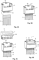
- Figure 6A is an exploded view of a multi-layer interface 14 comprising a functional layer 15 with a terminal 5, an electrically insulating layer 16 with a connector housing 3, and a decorative layer 17.
- the terminal 5 of the printed electronic circuitry 4 is inserted in the first electrically insulated connector housing 3.
- the connector housing 3 can be mechanically fixed to the substrate of the terminal 5 of the printed electronic circuitry 4 by closing a latch 11, as shown in Figure 6C .
- a card edge board comprising traces leading to the edge of the board is formed. These traces are either formed by the contacts of the terminal 5 of the printed electronic circuitry 4 or are in electrical contact to the contacts of the terminal 5 of the printed electronic circuitry 4.
- the terminal 5 and the connector housing 3 make up a male card edge connector 2, which can be used to connect the printed electronic circuitry 4.
- the male connector 2 can mate with a corresponding female connector 6 to form a connector system 1.
- the connector system 1 can be used to establish an electrical connection of the printed electronic circuitry 4 to an external module.
- Figure 7A is an exploded view of a multi-layer interface 14 comprising a functional layer 15 with a terminal 5, an electrically insulating layer 16 with a connector housing 3, and a decorative layer 17.
- the terminal 5 of the printed electronic circuitry 4 is over-molded with the first electrically insulated connector housing 3.
- the terminal 5 and the connector housing 3 make up a male card edge connector 2, which can be used to connect the printed electronic circuitry 4.
- the male connector 2 can mate with a corresponding female connector 6 to form a connector system 1.
- the connector system 1 can be used to establish an electrical connection of the printed electronic circuitry 4 to an external module.
- Figure 8A is an exploded view of a multi-layer interface 14 comprising a functional layer 15 with a terminal 5, an electrically insulating layer 16 with a connector housing 3, and a decorative layer 17, and crimps 13.
- crimp contacts 13 are crimped to the terminal 5 of the printed electronic circuitry 4.
- the crimp contacts 13 establish an electrical connection between the contacts of the terminal 5 and the tips 21 of the crimp contacts 13.
- the parts of the crimp contacts 13, which overhang the terminal 5, are inserted in the connector housing 3 of a male connector 2.
- Figure 8A shows that the tips 21 of the crimp contacts 13 are shaped as studs 23. When attached to the connector housing 3 of the male connecter 2, the studs 23 can be inserted into a female card edge connector 6 and establish an electrical connection thereto. This is shown in Figures 8D and 8E .
- Figure 9A is an exploded view of a multi-layer interface 14 comprising a functional layer 15 with a terminal 5, an electrically insulating layer 16 with a connector housing 7 of a female connector 6, and a decorative layer 17, and crimps 13.
- crimp contacts 13 are crimped to the terminal 5 of the printed electronic circuitry 4.
- the crimp contacts 13 establish an electrical connection between the contacts of the terminal 5 and the tips 21 of the crimp contacts 13.
- the parts of the crimp contacts 13, which overhang the terminal 5, are inserted in the connector housing 7 of a female connector 6.
- Figure 9A shows that the tips 21 of the crimp contacts 13 are shaped as clamps 22 with two separate arms.
- the clamps 22 When attached to the connector housing 7 of the female connecter 6, the clamps 22 can receive a male card edge connector 2 and establish an electrical connection thereto.
- This is shown in Figures 9D and 9E .
- REFERENCE NUMERALS Reference Numeral Description 1 connector system 2 male connector 3 first electrically insulated connector housing 4 printed electronic circuitry 5 terminal of the printed electronic circuitry 6 female connector 7 second electrically insulated connector housing 8 portion of the male connector formed as a board 9 edge 10 traces 11 latch 12 supporting unit 13 crimp 14 multi-layer interface 15 functional layer 16 electrically insulating layer 17 decorative layer 18 soldering contacts 19 catch mechanism 20 electrical leads 21 tip of the crimp 22 clamp 23 stud
Landscapes
- Engineering & Computer Science (AREA)
- Manufacturing & Machinery (AREA)
- Microelectronics & Electronic Packaging (AREA)
- Coupling Device And Connection With Printed Circuit (AREA)
Priority Applications (1)
| Application Number | Priority Date | Filing Date | Title |
|---|---|---|---|
| EP21208665.6A EP4184722A1 (de) | 2021-11-17 | 2021-11-17 | Elektrischer verbindungsstecker zum verbinden einer flexiblen gedruckten schaltung mit einem kabelbaum |
Applications Claiming Priority (1)
| Application Number | Priority Date | Filing Date | Title |
|---|---|---|---|
| EP21208665.6A EP4184722A1 (de) | 2021-11-17 | 2021-11-17 | Elektrischer verbindungsstecker zum verbinden einer flexiblen gedruckten schaltung mit einem kabelbaum |
Publications (1)
| Publication Number | Publication Date |
|---|---|
| EP4184722A1 true EP4184722A1 (de) | 2023-05-24 |
Family
ID=78676425
Family Applications (1)
| Application Number | Title | Priority Date | Filing Date |
|---|---|---|---|
| EP21208665.6A Pending EP4184722A1 (de) | 2021-11-17 | 2021-11-17 | Elektrischer verbindungsstecker zum verbinden einer flexiblen gedruckten schaltung mit einem kabelbaum |
Country Status (1)
| Country | Link |
|---|---|
| EP (1) | EP4184722A1 (de) |
Citations (11)
| Publication number | Priority date | Publication date | Assignee | Title |
|---|---|---|---|---|
| US5129840A (en) * | 1990-03-01 | 1992-07-14 | Yazaki Corporation | Electrical connector |
| US6146190A (en) * | 1998-06-01 | 2000-11-14 | Molex Incorporated | Electrical connector assembly for connecting flat flexible circuitry to discrete electrical terminals |
| US20050239322A1 (en) * | 2000-10-02 | 2005-10-27 | Alban Godefroy | Electrical connector module with housings for receiving forwardly-inserted female contacts |
| WO2008120513A1 (ja) * | 2007-03-29 | 2008-10-09 | Citizen Holdings Co., Ltd. | 積層基板の電極端子接続構造 |
| KR101543386B1 (ko) * | 2014-03-19 | 2015-11-20 | 한성전자 주식회사 | Ffc 커넥터 |
| EP3098696A1 (de) * | 2015-05-28 | 2016-11-30 | Alps Electric Co., Ltd. | Verbindungsvorrichtung |
| US20180331446A1 (en) * | 2017-05-10 | 2018-11-15 | Yazaki Corporation | Connector and manufacturing method of the same |
| US20190148857A1 (en) * | 2016-05-11 | 2019-05-16 | Autonetworks Technologies, Ltd. | Flat electric cable connection structure |
| US10431906B1 (en) * | 2018-07-12 | 2019-10-01 | Ford Global Technologies, Llc | Automotive wiring harness flat cable end termination |
| WO2020172743A1 (en) * | 2019-02-25 | 2020-09-03 | Reflex Photonics Inc. | Method and assembly for board to board connection of active devices |
| US20200366016A1 (en) * | 2019-05-15 | 2020-11-19 | Bizlink International Corp. | Connector assembly |
-
2021
- 2021-11-17 EP EP21208665.6A patent/EP4184722A1/de active Pending
Patent Citations (11)
| Publication number | Priority date | Publication date | Assignee | Title |
|---|---|---|---|---|
| US5129840A (en) * | 1990-03-01 | 1992-07-14 | Yazaki Corporation | Electrical connector |
| US6146190A (en) * | 1998-06-01 | 2000-11-14 | Molex Incorporated | Electrical connector assembly for connecting flat flexible circuitry to discrete electrical terminals |
| US20050239322A1 (en) * | 2000-10-02 | 2005-10-27 | Alban Godefroy | Electrical connector module with housings for receiving forwardly-inserted female contacts |
| WO2008120513A1 (ja) * | 2007-03-29 | 2008-10-09 | Citizen Holdings Co., Ltd. | 積層基板の電極端子接続構造 |
| KR101543386B1 (ko) * | 2014-03-19 | 2015-11-20 | 한성전자 주식회사 | Ffc 커넥터 |
| EP3098696A1 (de) * | 2015-05-28 | 2016-11-30 | Alps Electric Co., Ltd. | Verbindungsvorrichtung |
| US20190148857A1 (en) * | 2016-05-11 | 2019-05-16 | Autonetworks Technologies, Ltd. | Flat electric cable connection structure |
| US20180331446A1 (en) * | 2017-05-10 | 2018-11-15 | Yazaki Corporation | Connector and manufacturing method of the same |
| US10431906B1 (en) * | 2018-07-12 | 2019-10-01 | Ford Global Technologies, Llc | Automotive wiring harness flat cable end termination |
| WO2020172743A1 (en) * | 2019-02-25 | 2020-09-03 | Reflex Photonics Inc. | Method and assembly for board to board connection of active devices |
| US20200366016A1 (en) * | 2019-05-15 | 2020-11-19 | Bizlink International Corp. | Connector assembly |
Similar Documents
| Publication | Publication Date | Title |
|---|---|---|
| US10756466B2 (en) | Connector | |
| US7547214B2 (en) | Edge-to-edge connector system for electronic devices | |
| CN102099970B (zh) | 具有电容耦合匹配接口的输入/输出连接器 | |
| US7497695B2 (en) | Connection structure for printed wiring board | |
| CN1104760C (zh) | 具有集成电源线的表面安装连接器 | |
| US5244395A (en) | Circuit interconnect system | |
| EP1280240B1 (de) | Einsteckbares elektronisches Modul mit flexibler Schaltungseinrichtung und entsprechendem Auffang | |
| US6840783B2 (en) | Press-fit bus bar distributing power | |
| CN1127176C (zh) | 用于将扁平软电路系统连接到离散终端的电连接器组件 | |
| US6508661B1 (en) | Flexible printed circuit connector | |
| US7445462B2 (en) | Method of connecting signal lines, a printed circuit board assembly and electronic apparatus having the same | |
| US20110117757A1 (en) | Contacting of multipoint plug connectors via intermediate printed-circuit boards | |
| US5816829A (en) | Electrical connector having arrays of terminals for a multi-conductor cable | |
| JP3970547B2 (ja) | フレキシブルプリント回路とワイヤハーネスの接続用コネクタ | |
| EP4184722A1 (de) | Elektrischer verbindungsstecker zum verbinden einer flexiblen gedruckten schaltung mit einem kabelbaum | |
| US20040077189A1 (en) | Adhesive interconnector | |
| US5611697A (en) | Connector module with molded upper section including molded socket, socket pins, and positioning elements | |
| US11462851B2 (en) | Machine case and cable connector assembly | |
| US3774140A (en) | Connectorless plug-in printed wiring card | |
| US6109932A (en) | Three-dimensional electrical interconnection system | |
| JPH08148204A (ja) | フラットケーブルの接続方法及びコネクタ | |
| US20240079802A1 (en) | Electrical Connection Assembly and Electrical Connection Device | |
| CN117767046A (zh) | 连接器 | |
| CN117791208A (zh) | 连接器、连接器组装体和连接方法 | |
| JPH0446394Y2 (de) |
Legal Events
| Date | Code | Title | Description |
|---|---|---|---|
| PUAI | Public reference made under article 153(3) epc to a published international application that has entered the european phase |
Free format text: ORIGINAL CODE: 0009012 |
|
| STAA | Information on the status of an ep patent application or granted ep patent |
Free format text: STATUS: THE APPLICATION HAS BEEN PUBLISHED |
|
| AK | Designated contracting states |
Kind code of ref document: A1 Designated state(s): AL AT BE BG CH CY CZ DE DK EE ES FI FR GB GR HR HU IE IS IT LI LT LU LV MC MK MT NL NO PL PT RO RS SE SI SK SM TR |
|
| STAA | Information on the status of an ep patent application or granted ep patent |
Free format text: STATUS: REQUEST FOR EXAMINATION WAS MADE |
|
| 17P | Request for examination filed |
Effective date: 20231121 |
|
| RBV | Designated contracting states (corrected) |
Designated state(s): AL AT BE BG CH CY CZ DE DK EE ES FI FR GB GR HR HU IE IS IT LI LT LU LV MC MK MT NL NO PL PT RO RS SE SI SK SM TR |