EP4183899B1 - Betriebsunterstützungsverfahren, betriebsunterstützungsvorrichtung, betriebsunterstützungssystem und betriebsunterstützungsprogramm - Google Patents
Betriebsunterstützungsverfahren, betriebsunterstützungsvorrichtung, betriebsunterstützungssystem und betriebsunterstützungsprogramm Download PDFInfo
- Publication number
- EP4183899B1 EP4183899B1 EP21843512.1A EP21843512A EP4183899B1 EP 4183899 B1 EP4183899 B1 EP 4183899B1 EP 21843512 A EP21843512 A EP 21843512A EP 4183899 B1 EP4183899 B1 EP 4183899B1
- Authority
- EP
- European Patent Office
- Prior art keywords
- state
- electrolytic apparatus
- determination result
- information
- operation support
- Prior art date
- Legal status (The legal status is an assumption and is not a legal conclusion. Google has not performed a legal analysis and makes no representation as to the accuracy of the status listed.)
- Active
Links
Images




Classifications
-
- C—CHEMISTRY; METALLURGY
- C25—ELECTROLYTIC OR ELECTROPHORETIC PROCESSES; APPARATUS THEREFOR
- C25B—ELECTROLYTIC OR ELECTROPHORETIC PROCESSES FOR THE PRODUCTION OF COMPOUNDS OR NON-METALS; APPARATUS THEREFOR
- C25B15/00—Operating or servicing cells
- C25B15/02—Process control or regulation
- C25B15/023—Measuring, analysing or testing during electrolytic production
-
- C—CHEMISTRY; METALLURGY
- C25—ELECTROLYTIC OR ELECTROPHORETIC PROCESSES; APPARATUS THEREFOR
- C25B—ELECTROLYTIC OR ELECTROPHORETIC PROCESSES FOR THE PRODUCTION OF COMPOUNDS OR NON-METALS; APPARATUS THEREFOR
- C25B1/00—Electrolytic production of inorganic compounds or non-metals
- C25B1/01—Products
- C25B1/34—Simultaneous production of alkali metal hydroxides and chlorine, oxyacids or salts of chlorine, e.g. by chlor-alkali electrolysis
- C25B1/46—Simultaneous production of alkali metal hydroxides and chlorine, oxyacids or salts of chlorine, e.g. by chlor-alkali electrolysis in diaphragm cells
-
- Y—GENERAL TAGGING OF NEW TECHNOLOGICAL DEVELOPMENTS; GENERAL TAGGING OF CROSS-SECTIONAL TECHNOLOGIES SPANNING OVER SEVERAL SECTIONS OF THE IPC; TECHNICAL SUBJECTS COVERED BY FORMER USPC CROSS-REFERENCE ART COLLECTIONS [XRACs] AND DIGESTS
- Y02—TECHNOLOGIES OR APPLICATIONS FOR MITIGATION OR ADAPTATION AGAINST CLIMATE CHANGE
- Y02E—REDUCTION OF GREENHOUSE GAS [GHG] EMISSIONS, RELATED TO ENERGY GENERATION, TRANSMISSION OR DISTRIBUTION
- Y02E60/00—Enabling technologies; Technologies with a potential or indirect contribution to GHG emissions mitigation
- Y02E60/30—Hydrogen technology
- Y02E60/36—Hydrogen production from non-carbon containing sources, e.g. by water electrolysis
Definitions
- the present invention relates to an operation support method, an operation support device, an operation support system, and an operation support program.
- Patent document 1 relates to a method and a device for capturing, monitoring, displaying, and diagnosing operation parameters of an electrolysis apparatus.
- Patent document 1 describes that "A monopolar electrolyzer is hereinafter considered as a single cell unit, and a bipolar electrolyzer is considered as a plurality of unit cells. The reading of a voltage is measured for each unit cell. The present invention enables the detection of faults and events in each unit cell" (paragraph 0014).
- Patent Document 2 aims to provide an ionic water preparation device preparing strong acid water, according to which "When a strong acidic water mode switch is pushed, other modes are cancelled and the strongly acidic water mode is set.
- the flow rate is adjusted by issuing a flow rate adjusting signal for adjusting the optimum flow rate when strongly acidic water is prepared from a control section, and a strongly acidic level signal for setting the strongly acidic level of the optimum flow rate is transmitted from the control section to an electolytic level control circuit and the electroytic voltage of strongly acidic level is generated in the electlytic voltage generating circuit and applied to an electrolytic cell to prepare the strongly acidic water.
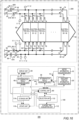
- Fig. 1 shows an example of an electrolytic apparatus 200 according to one embodiment of the present invention.
- the electrolytic apparatus 200 of the present example includes an electrolyzer 90, an introduction tube 92, an introduction tube 93, a discharge tube 94, a discharge tube 95, and one or more switching portions 66.
- the electrolytic apparatus 200 of the present example includes four switching portions 66 (switching portions 66-1 to 66-4).
- the switching portion 66-1 to the switching portion 66-4 are provided in the introduction tube 92, the introduction tube 93, the discharge tube 94, and the discharge tube 95, respectively.
- the switching portion 66 is, for example, a valve.
- the electrolytic apparatus 200 is an apparatus that electrolyzes an electrolytic solution.
- the electrolytic apparatus 200 is an apparatus that generates Cl (chlorine) and NaOH (sodium hydroxide) by electrolyzing an aqueous solution of NaCl (sodium chloride).
- a product produced by the generation with the electrolytic apparatus 200 is defined as a product P.
- the electrolyzer 90 is a tank for electrolyzing an electrolytic solution.
- the electrolyzer 90 in the present example is a tank for electrolyzing an aqueous solution of NaCl (sodium chloride).
- the electrolyzer 90 may include a plurality of electrolysis cells 91 (electrolysis cells 91-1 to 91-N, where N is an integer of 2 or more).
- the electrolytic apparatus 200 may be an apparatus that generates H 2 (hydrogen) and O 2 (oxygen) by electrolyzing H 2 O (water).
- the electrolyzer 90 may be a tank that electrolyzes H 2 O (water).
- the introduction tube 92 and the introduction tube 93 are connected to the electrolyzer 90.
- the introduction tube 92 and the introduction tube 93 are connected to each of the electrolysis cell 91-1 to the electrolysis cell 91-N.
- Liquid 70 is introduced into each of the electrolysis cells 91-1 to 91-N.
- the liquid 70 may be introduced into each of the electrolysis cells 91-1 to 91-N after passing through the introduction tube 92.
- the liquid 70 is an aqueous solution of NaCl (sodium chloride).
- Liquid 72 is introduced into each of the electrolysis cells 91-1 to 91-N.
- the liquid 72 may be introduced into each of the electrolysis cells 91-1 to 91-N after passing through the introduction tube 93.
- the liquid 72 may be an aqueous solution of NaOH (sodium hydroxide) or may be an aqueous solution of KOH (potassium hydroxide).
- the discharge tube 94 and discharge tube 95 are connected to the electrolyzer 90.
- the discharge tube 94 and the discharge tube 95 are connected to each of the electrolysis cell 91-1 to the electrolysis cell 91-N.
- Liquid 74 and gas 77 (described below) are derived from the electrolyzer 90.
- the electrolytic apparatus 200 may include a separation device that separates the liquid 74 and the gas 77 (described below).
- the liquid 74 and the gas 77 (described below) may be separated into the liquid 74 and the gas 77 (described below) by the separation device after passing through the discharge tube 94.
- the separated liquid 74 may be reused to generate the liquid 70 outside the electrolytic apparatus 200 or may be discarded.
- the liquid 74 is an aqueous solution of NaCl (sodium chloride).
- the gas 77 (described below) may be collected as a product outside the electrolytic apparatus 200.
- the gas 77 (described below) is Cl 2 (chlorine).
- Liquid 76 and gas 78 are derived from the electrolyzer 90.
- the liquid 76 and the gas 78 may be separated into the liquid 76 and the gas 78 (described below) by the separation device described above after passing through the discharge tube 95.
- the separated liquid 76 may be collected as a product outside the electrolytic apparatus 200.
- the liquid 76 is an aqueous solution of NaOH (sodium hydroxide).
- the gas 78 (described below) may be collected as a product outside the electrolytic apparatus 200 or may be discarded.
- the gas 78 (described below) is H 2 (hydrogen).
- the switching portion 66-1 controls a flow rate of the liquid 70 flowing through the introduction tube 92.
- the switching portion 66-1 may control a flow rate per unit time of the liquid 70 flowing through the introduction tube 92 or an integrated value of the flow rate over a predetermined time.
- the switching portion 66-2 controls a flow rate of the liquid 72 flowing through the introduction tube 93.
- the switching portion 66-2 may control a flow rate per unit time of the liquid 72 flowing through the introduction tube 93 or an integrated value of the flow rate over a predetermined time.
- the switching portion 66-3 controls the pressure of the gas 77 (described below) flowing through the discharge tube 94.
- the switching portion 66-4 controls the pressure of the gas 78 (described below) flowing through the discharge tube 95.
- instruments 11 are provided in the introduction tube 92, the introduction tube 93, the discharge tube 94, and the discharge tube 95.
- an instrument 11-1 is a pressure gauge
- an instrument 11-2 is a flow instrument
- an instrument 11-3 (described below) is a level gauge.
- the instruments 11-1 may be provided in the introduction tube 92 and the introduction tube 93.
- the instruments 11-2 may be provided in the introduction tube 92, the introduction tube 93, the discharge tube 94, and the discharge tube 95.
- the instrument 11-1 provided in the introduction tube 92 may measure the pressure of a chlorine gas (Cl 2 ) in an anode chamber 79 (described below).
- the instrument 11-1 provided in the introduction tube 93 may measure the pressure of a hydrogen gas (H 2 ) in a cathode chamber 98 (described below).
- the instrument 11-2 provided in the introduction tube 92 may measure a flow rate per unit time of the liquid 70 flowing through the introduction tube 92.
- the instrument 11-2 provided in the introduction tube 93 may measure a flow rate per unit time of the liquid 72 flowing through the introduction tube 93.
- the instrument 11-2 provided in the discharge tube 94 may measure a flow rate per unit time of the liquid 74 flowing through the discharge tube 94.
- the instrument 11-2 provided in the discharge tube 95 may measure a flow rate per unit time of the liquid 76 flowing through the discharge tube 95.
- At least one of the switching portion 66-1 to the switching portion 66-4 may be a manual manipulation target switching portion 660.
- the manual manipulation target switching portion 660 is a switching portion 66 that is a target to be manually manipulated by the operator.
- the switching portion 66 other than the manual manipulation target switching portion 660 may be an automatic control target switching portion 670.
- the automatic control target switching portion 670 is switching portion 66 that is a target of automatic control in the electrolytic apparatus 200 and is a target of automatic control by the operation support device 100 (described below).
- the switching portion 66 When the pressure measured by the instrument 11-1 is less than a predetermined pressure, the flow rate measured by the instrument 11-2 is less than a predetermined flow rate, and the liquid level measured by the instrument 11-3 (described below) is less than a predetermined liquid level height, the switching portion 66 is operating normally. When the switching portion 66 is operating normally, all the switching portions 66 are the automatic control target switching portions 670.
- Fig. 1 is an example of a case where the switching portion 66-3 is the manual manipulation target switching portion 660, and the switching portion 66-1, the switching portion 66-2, and the switching portion 66-4 are the automatic control target switching portions 670.
- Fig. 2 shows an example of details of one electrolysis cell 91 in Fig. 1 .
- the electrolysis cell 91 of the present example includes an anode 80, a cathode 82, and an ion exchange membrane 84.
- the anode chamber 79 and the cathode chamber 98 are provided inside the electrolysis cell 91.
- the ion exchange membrane 84 partitions the anode chamber 79 and the cathode chamber 98.
- the anode 80 is arranged in the anode chamber 79.
- the cathode 82 is arranged in the cathode chamber 98.
- the introduction tube 92 and the discharge tube 94 are connected to the anode chamber 79.
- the introduction tube 93 and the discharge tube 95 are connected to the cathode chamber 98.
- the ion exchange membrane 84 is a membrane-shaped substance that prevents passage of ions having a sign different from that of the ions arranged in the ion exchange membrane 84 and allows passage of only ions having the same sign.
- the ion exchange membrane 84 is a membrane that allows Na + (sodium ions) to pass and prevents Cl - (chlorine ions) from passing.
- the electrolysis cell 91 has a bottom surface 81, an inner side surface 83, and a ceiling surface 85.
- the anode chamber 79 and the cathode chamber 98 are spaces surrounded by the bottom surface 81, the inner side surface 83, and the ceiling surface 85.
- the anode 80 and the cathode 82 may be maintained at predetermined positive and negative potentials, respectively.
- the liquid 70 introduced into anode chamber 79 and the liquid 72 introduced into cathode chamber 98 are electrolyzed by a potential difference between the anode 80 and the cathode 82.
- the following chemical reaction occurs. [Chemical Formula 1] 2Cl - ⁇ Cl 2 + 2e -
- NaCl sodium chloride
- NaCl sodium chloride
- Cl - chlorine ion
- a chlorine gas Cl 2
- Na + (sodium ions) moves from the anode chamber 79 to the cathode chamber 98 via the ion exchange membrane 84 by an attractive force from the cathode 82.
- liquid 73 may be retained.
- the liquid 73 in the present example is an aqueous solution of NaCl (sodium chloride).
- the Na + (sodium ion) concentration and the Cl - (chlorine ion) concentration of the liquid 73 may be less than the Na + (sodium ion) concentration and the Cl - (chlorine ion) concentration of the liquid 70.
- a hydrogen gas (H 2 ) and a hydroxide ion (OH - ) are generated by the chemical reaction represented by Chemical Formula 2.
- liquid 75 in which hydroxide ions (OH - ) generated by the chemical reaction represented by Chemical Formula 2 and Na + (sodium ions) moved from the anode chamber 79 are dissolved may be retained.
- the liquid 75 in the present example is an aqueous solution of NaOH (sodium hydroxide).
- the instruments 11-3 may be provided in the anode chamber 79 and the cathode chamber 98.
- the instrument 11-3 is a level gauge.
- the instrument 11-3 may be a limit switch.
- the limit switch is a switch having a microswitch built in, and is a switch in which the microswitch is incorporated in a sealing case or the like that protects the microswitch from H 2 O (water) or the like.
- the limit switch is a switch configured to operate even under an environment where mechanical stress or the like is received from the outside of the limit switch.
- the instrument 11-3 provided in the anode chamber 79 senses whether the liquid level of the liquid 73 in the anode chamber 79 has reached the predetermined liquid level height.
- the instrument 11-3 provided in the cathode chamber 98 senses whether the liquid level of the liquid 75 in the cathode chamber 98 has reached the predetermined liquid level height.
- Fig. 3 is a diagram showing the vicinity of the ion exchange membrane 84 in the electrolysis cell 91 shown in Fig. 2 to an enlarged scale.
- An anion group 86 is fixed to the ion exchange membrane 84 of the present example. Since anions are repelled by the anion group 86, the anions hardly pass through the ion exchange membrane 84. In the present example, the anions are Cl - (chlorine ion). Since cations 71 are not repelled by the anion group 86, the cations can pass through the ion exchange membrane 84. In the present example, the cations 71 are Na + (sodium ion).
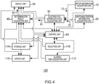
- Fig. 4 shows an example of a block diagram of the operation support device 100 according to one embodiment of the present invention.
- the operation support device 100 supports the operation of the electrolytic apparatus 200 (see Fig. 1 ).
- the operation support device 100 includes an instrument information acquisition unit 10, a switching portion information acquisition unit 20, an electrolytic apparatus state acquisition unit 30, a determination result acquisition unit 40, and a control unit 60.
- the operation support device 100 is, for example, a computer including a CPU, a memory, an interface, and the like.
- the control unit 60 may be the CPU.
- an operation support program for executing an operation support method to be described below may be installed in the computer, and an operation support program for causing the computer to function as the operation support device 100 may be installed in the computer.
- the computer may be a tablet computer.
- the operation support device 100 may or may not include a display unit 50, a selection unit 110, an elapsed time acquisition unit 112, a storage unit 114, and an update unit 116.
- the operation support device 100 of the present example includes the display unit 50, the selection unit 110, the elapsed time acquisition unit 112, the storage unit 114, and the update unit 116.
- the display unit 50 and the storage unit 114 separate from the operation support device 100 may be connected to the operation support device 100 via a predetermined interface.
- the instrument information acquisition unit 10 acquires instrument information 12 from the instrument 11 (see Figs. 1 and 2 ) included in the electrolytic apparatus 200.
- the instrument information 12 is measurement data by the instrument 11.
- the measurement data is data obtained by measuring parameters regarding the electrolytic apparatus 200.
- the parameters may include the flow rates of the liquid 70 (see Fig. 1 ) and the liquid 72 (see Fig. 1 ) and the flow rates of the liquid 74 (see Fig. 1 ) and the liquid 75 (see Fig. 1 ).
- the parameters may include the liquid level height of the liquid 73 (see Fig. 2 ) in the anode chamber 79 and the pressure of the gas 77 (see Fig. 2 ).
- the parameters may include the liquid level height of the liquid 75 (see Fig. 2 ) in the cathode chamber 98 and the pressure of the gas 78 (see Fig. 2 ).
- the switching portion information acquisition unit 20 acquires switching portion information 21 indicating information regarding the switching portion 66.
- the switching portion 66 controls at least one of the flow rate of fluid or the pressure of gas.
- the fluid may be at least any one of the liquid 70 (see Fig. 1 ), the liquid 72 (see Fig. 1 ), the liquid 74 (see Fig. 1 ), or the liquid 76 (see Fig. 1 ).
- the gas may be at least one of the gas 77 (see Fig. 2 ) or the gas 78 (see Fig. 2 ).
- the switching portion information 21 may refer to information indicating whether the switching portion 66 is in an open state or a closed state or may refer to information indicating whether the switching portion 66 is in an intermediate state between the open state and the closed state.
- the switching portion information 21 may refer to information on the time required for the switching portion 66 to switch from the open state to the closed state or from the closed state to the open state.
- the electrolytic apparatus state acquisition unit 30 acquires electrolytic apparatus state information 31 indicating the state of the electrolytic apparatus 200 (see Fig. 1 ).
- the electrolytic apparatus state acquisition unit 30 acquires the electrolytic apparatus state information 31 on the basis of at least one of the instrument information 12 or the switching portion information 21.
- the state of the electrolytic apparatus 200 may further include process information indicating which process the electrolytic apparatus 200 is currently in.
- the state of the electrolytic apparatus 200 refers to whether the electrolytic apparatus 200 requires the work by an operator.
- the state of not requiring the work by the operator is a case where the electrolytic apparatus 200 is in a normal state.
- a case where the electrolytic apparatus 200 is in the normal state is a case where the pressure measured by the instrument 11-1 is less than the predetermined pressure, the flow rate measured by the instrument 11-2 is less than the predetermined flow rate, and the liquid level measured by the instrument 11-3 is less than the predetermined liquid level height, so that the switching portion 66 is operating normally.
- the state of requiring the work by the operator includes a case where the electrolytic apparatus 200 is in the normal state and a case where the electrolytic apparatus is in an abnormal state.
- a state where the electrolytic apparatus 200 is in the normal state and requires the work by the operator refers to predetermined work by the operator, for example, in the case of a leak test or the like of the ion exchange membrane 84.
- a case where the electrolytic apparatus 200 is in the abnormal state refers to a state where the electrolytic apparatus 200 is not automatically controlled due to occurrence of some abnormality in the electrolytic apparatus 200.
- the abnormal state may include a state where the switching portion 66 is not fully opened or fully closed, and may include a state where the opening/closing speed of the switching portion 66 is lower than a predetermined speed.
- the abnormal state may include a state where a time required to execute each process in one or more predetermined processes exceeds a predetermined allowable time, a state where a pressure of at least one of the gas 77 (see Fig. 2 ) or the gas 78 (see Fig.
- the abnormal state may include a case where a pressure difference between the anode chamber 79 and the cathode chamber 98 is equal to or larger than a predetermined allowable pressure difference.
- the abnormal state may include a case where at least one of the liquid level height of the liquid 73 in the anode chamber 79 or the liquid level height of the liquid 75 in the cathode chamber 98 is equal to or higher than a predetermined liquid level height.
- the abnormal state may include a case where a difference between the liquid level height of the liquid 73 in the anode chamber 79 and the liquid level height of the liquid 75 in the cathode chamber 98 is equal to or larger than a predetermined allowable difference.
- the introduction tube 92 may be provided with a plurality of instruments 11-1, and the introduction tube 93 may be provided with a plurality of instruments 11-1.
- the introduction tube 92 may be provided with a plurality of instruments 11-2, and the introduction tube 93 may be provided with a plurality of instruments 11-2.
- the discharge tube 94 may be provided with a plurality of instruments 11-2, and the discharge tube 95 may be provided with a plurality of instruments 11-2.
- the electrolytic apparatus state acquisition unit 30 may acquire the electrolytic apparatus state information 31 on the basis of a difference between the pressures measured by the two instruments 11-1.
- the electrolytic apparatus state information 31 may include information that the electrolytic apparatus 200 is in the normal state and information that the electrolytic apparatus 200 is in the abnormal state.
- the work by the operator refers to the manual work by the operator.
- the target of the work by the operator may include at least one switching portion 66 and the electrolyzer 90.
- the work by the operator may include at least any one of the manipulation of the manual manipulation target switching portion 660 (see Fig. 1 ), the confirmation for the electrolytic apparatus 200, or the confirmation for the components of the electrolytic apparatus 200.
- the manipulation of the manual manipulation target switching portion 660, the confirmation for the electrolytic apparatus 200, and the confirmation for the components of the electrolytic apparatus 200 may be predetermined work by the operator when the electrolytic apparatus 200 is not in the abnormal state.
- the manual manipulation target switching portion 660 is at least one of the switching portion 66-1 to the switching portion 66-4.
- the confirmation for the electrolytic apparatus 200 may include confirmation work on whether at least one of the liquid 73 or the liquid 75 is leaking from the electrolyzer 90.
- the confirmation for the components of the electrolytic apparatus 200 may include confirmation work on whether there is no damage in the ion exchange membrane 84.
- the confirmation work on whether there is no damage in the ion exchange membrane 84 may include work of detaching a nozzle arranged at an outlet on the cathode 82 side of the ion exchange membrane 84 of the electrolysis cell 91, application of soap water to the nozzle, confirmation of swelling of foam of the soap water, and the like.
- the control unit 60 controls acquisition of the instrument information 12 by the instrument information acquisition unit 10.
- the control unit 60 controls acquisition of the switching portion information 21 by the switching portion information acquisition unit 20.
- the control unit 60 controls acquisition of the electrolytic apparatus state information 31 by the electrolytic apparatus state acquisition unit 30.
- the state of the electrolytic apparatus 200 requiring the work by the operator is defined as a first state S1 of the electrolytic apparatus 200.
- the first state S1 includes a case where the electrolytic apparatus 200 is in the normal state and a case where the electrolytic apparatus is in the abnormal state.
- the state of the electrolytic apparatus 200 not requiring the work by the operator is defined as a second state S2 of the electrolytic apparatus 200.
- the second state S2 is a case where the pressure measured by the instrument 11-1 is less than the predetermined pressure, the flow rate measured by the instrument 11-2 is less than the predetermined flow rate, and the liquid level measured by the instrument 11-3 is less than the predetermined liquid level height, so that the switching portion 66 is operating normally.
- the control unit 60 When the electrolytic apparatus 200 is in the first state S1, the control unit 60 does not control at least one of the switching portions 66, and controls the display unit 50 such that the display unit 50 performs display to prompt a work by the operator.
- the control unit 60 controls all switching portions 66.
- the first condition C1 may be the state of the electrolytic apparatus 200 in which predetermined work by the operator is assumed.
- the first condition C1 is the manual confirmation or the like for the electrolyzer 90 by the operator when the pressure of at least one of the gas 77 or the gas 78 is equal to or higher than a predetermined pressure Pr.
- the second condition C2 may be a condition that satisfies a predetermined standard Std to be described below.
- a predetermined standard Std for example, as described below, when the standard Std is the predetermined pressure Pr of at least one of the gas 77 or the gas 78 or when the standard Std is a predetermined pressure difference Dpr between the gas 77 and the gas 78, the electrolytic apparatus state information 31 satisfies the second condition C2 (satisfies the standard Std).
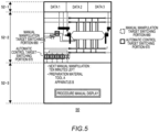
- Fig. 5 shows an example of the display unit 50.
- the display unit 50 is, for example, a monitor, a display, or the like.
- the display unit 50 may be the display of the tablet computer.
- the display unit 50 of the present example includes three display regions 52 (a display region 52-1, a display region 52-2, and a display region 52-3).
- the instrument information 12 is displayed in the display region 52-1.
- the display region 52-1 is further divided into three regions indicated by data 1 to data 3.
- information of the instrument 11-1 pressure gauge
- information of the instrument 11-2 flow instrument
- information of the instrument 11-3 liquid level gauge
- the state of the electrolytic apparatus 200 is schematically displayed.
- the introduction tube 92, the introduction tube 93, the discharge tube 94, the discharge tube 95, the switching portion 66, and the electrolyzer 90 in the electrolytic apparatus 200 shown in Fig. 1 are schematically shown.
- process information in the operation of the electrolytic apparatus 200 is displayed.
- the process information may include at least any one of a current process of the electrolytic apparatus 200, a next process of the current process, or a time from the current time to the next process.
- the process information may also include information on tools or the like necessary for the work by the operator.
- a button for causing a procedure manual indicating the procedure of the work by the operator to be displayed on the display region 52-3 may be further displayed.
- the control unit 60 controls the display unit 50 to display the electrolytic apparatus state information 31.
- the electrolytic apparatus state information 31 is based on at least one of the instrument information 12 or the switching portion information 21.
- the instrument information 12 may be measurement data by the instrument 11, and the switching portion information 21 may refer to information indicating whether the switching portion 66 is in the open state or the closed state.
- the measurement data by the instrument 11 may include the flow rate of the fluid and the pressure of the gas, and the switching portion 66 controls at least one of the flow rate of the fluid or the pressure of the gas.
- the electrolytic apparatus state information 31 based on at least one of the instrument information 12 or the switching portion information 21 is displayed on the display unit 50, so that the operator can easily and accurately recognize the work on the electrolytic apparatus 200.
- the control unit 60 may control the display unit 50 to display an indication corresponding to the determination result 41 acquired by the determination result acquisition unit 40.
- the indication corresponding to the determination result 41 refers to, for example, an indication that prompts a work by the operator when the electrolytic apparatus 200 is in the first state S1.
- the indication corresponding to the determination result 41 refers to an indication indicating a case where the electrolytic apparatus 200 is in the second state S2, for example, a case where the pressure measured by the instrument 11-1 is less than the predetermined pressure, the flow rate measured by the instrument 11-2 is less than the predetermined flow rate, and the liquid level measured by the instrument 11-3 is less than the predetermined liquid level height, so that the switching portion 66 is operating normally.
- the display unit 50 may separately display the manual manipulation target switching portion 660 and one or more automatic control target switching portions 670.
- Fig. 5 is an example of a display manner of the display unit 50 in a case where the determination result acquisition unit 40 acquires the determination result 41 that it is determined that the electrolytic apparatus 200 is currently in the second state S2 (normal state) and in a case where predetermined work by the operator is required in the next process.
- buttons for causing a next process in the operation of the electrolytic apparatus 200, a time from a current process to the next process, tools or the like necessary for the work by the operator in the next process, and a procedure manual indicating the procedure of the work by the operator to be displayed are displayed in the display region 52-3.
- the operator can cause the procedure manual to be displayed on the display unit 50 by pressing the button. As a result, the operator is less likely to mistake the procedure of the work.
- Fig. 6 shows another example of the display manner on the display unit 50.
- Fig. 6 is an example of the display manner of the display unit 50 when the determination result acquisition unit 40 acquires the determination result 41 that it is determined that the electrolytic apparatus 200 is currently in the abnormal state (included in the first state S1).
- the target of the work by the operator is the switching portion 66.
- three switching portions 66 which are the targets of the work by the operator are shown as the manual manipulation target switching portions 660.
- the display unit 50 may display the manipulation order of the manual manipulation target switching portion 660.
- the manipulation order of the three manual manipulation target switching portions 660 is indicated by circled numbers 1 to 3. Since the manipulation order of the manual manipulation target switching portion 660 is displayed on the display unit 50, the operator can easily manipulate the manual manipulation target switching portion 660. The operator is less likely to mistake the manipulation order of the manual manipulation target switching portion 660.
- the display unit 50 may sequentially display the manual manipulation target switching portion 660, which is the current manipulation target, on the basis of the manipulation order of the manual manipulation target switching portion 660.
- the control unit 60 may control the display unit 50 to sequentially display the manual manipulation target switching portion 660 which is the current manipulation target, for example, by causing the broken line frame surrounding the manual manipulation target switching portion 660 which is the current manipulation target among the three manual manipulation target switching portions 660 indicated by the broken line frames to blink.
- the operator is less likely to erroneously manipulate the manual manipulation target switching portion 660 which is not the current manipulation target.
- control unit 60 may control the display unit 50 to display another manual manipulation target switching portion 660, for example, by causing a broken line frame surrounding the another manual manipulation target switching portion 660 to blink.
- the control unit 60 causes the broken line frame surrounding the manual manipulation target switching portion 660 to blink or the like, the display of the circled numbers 1 to 3 shown in Fig. 6 may not be displayed.
- the display unit 50 may further display a procedure for changing the state from the first state S1 to the second state S2.
- the state of the electrolytic apparatus 200 is the abnormal state.
- the display unit 50 when the determination result acquisition unit 40 acquires the determination result 41 that it is determined that the state of the electrolytic apparatus 200 is the abnormal state, the display unit 50 further displays a procedure for changing the state from the first state S1 to the second state S2.
- the display unit 50 may further display a procedure for changing the state from the first state S1 to the second state S2 by the control unit 60 automatically controlling the electrolytic apparatus 200.
- the control unit 60 automatically controlling the electrolytic apparatus 200.
- the production efficiency refers to a production amount per unit time of the product P.
- a button for causing the procedure manual indicating the procedure of the work by the operator to be displayed may be displayed in the display region 52-3.
- the operator can cause a procedure manual indicating a procedure for changing the state from the first state S1 to the second state S2 to be displayed on the display unit 50 by pressing the button.
- the procedure may be manually performed by the operator, or may be automatically performed by the automatic control of the control unit 60.
- Fig. 7 shows another example of the display manner on the display unit 50.
- Fig. 7 is an example of the display manner after the button for causing the procedure manual indicating the procedure of the work by the operator to be displayed is pressed in Fig. 6 .
- the procedure of the work by the operator is defined as a procedure P.
- the procedure P for changing the state of the electrolytic apparatus 200 from the first state S1 to the second state S2 may be a procedure P selected from one or more types of procedures P of the process of the operator.
- the display unit 50 may display the plurality of procedures P.
- the operator may select one procedure P from the plurality of procedures P on the display unit 50.
- three procedures P (procedures P1 to P3) are shown.
- the procedure P selected by the operator may be displayed separately from other procedures P.
- the procedure P selected by the operator is a procedure P2.
- a frame for displaying the procedure P2 is indicated by a thicker line than those of the frames for displaying the other procedures P, whereby the procedure P selected by the operator and the other procedures P are displayed separately.
- the display unit 50 may display the procedure P for changing the state of the electrolytic apparatus 200 to the second state S2 by eliminating the abnormal state.
- the display unit 50 may display a procedure P of predetermined work by the operator, the procedure being the procedure P for changing the state of the electrolytic apparatus 200 from the first state S1 to the second state S2.
- Fig. 8 shows another example of the display manner on the display unit 50.
- Fig. 8 is an example of the display manner after the state of the electrolytic apparatus 200 is changed from the first state S1 to the second state S2 by the procedure P (procedure P2) selected in Fig. 7 .
- the determination result acquisition unit 40 may acquire the determination result 41 obtained by further determining whether the state of the electrolytic apparatus 200 has changed from the first state S1 to the second state S2 according to the procedure P.
- the control unit 60 may control the display unit 50 to display all the switching portions 66 as the automatic control target switching portion 670.
- all the switching portions 66 are surrounded by solid line frames.
- Fig. 9 shows another example of the display manner on the display unit 50.
- Fig. 9 is an example of the display manner after the state of the electrolytic apparatus 200 is not changed from the first state S1 to the second state S2 by the procedure P (procedure P2) selected in Fig. 7 within a time less than a predetermined allowable time Tth.
- the elapsed time acquisition unit 112 may acquire an elapsed time T for which the first state S1 continues after acquiring the determination result 41 that the state of the electrolytic apparatus 200 is the first state S1.
- the elapsed time acquisition unit 112 may acquire the elapsed time T while the operator is performing the work for changing the state of the electrolytic apparatus 200 from the first state S1 to the second state S2 by the procedure P2.
- the procedure P2 is defined as an initial procedure P2.
- the display unit 50 may further display another procedure P different from the initial procedure P2.
- the display unit 50 displays the procedure P1 different from the initial procedure P2.
- the procedure P1 may include another procedure from which the order of the work on the plurality of manual manipulation target switching portions 660, the order of work on the manual manipulation target switching portion 660 and the electrolyzer 90, and the like in the initial procedure P2 are different.
- the procedure P1 may be the procedure of the automatic control by the control unit 60.
- the display unit 50 may display the procedure P1 in the display region 52-3.
- the predetermined allowable time Tth may be a time for which the safety of the electrolytic apparatus 200 can be secured even when the first state S1 is continued.
- the first state S1 is the abnormal state
- the liquid 70, the liquid 72, the liquid 75, and the liquid 75 are likely to retain in the electrolyzer 90.
- each member in the electrolyzer 90 may be deteriorated by the liquid 70, the liquid 72, the liquid 75, and the liquid 75.
- the predetermined allowable time Tth may be, for example, a time within a range in which the deterioration does not occur.
- Fig. 10 shows another example of the display manner on the display unit 50.
- Fig. 10 shows an example of the display manner of the display unit 50 when the determination result acquisition unit 40 acquires the determination result 41 that it is determined that the electrolytic apparatus 200 is currently in the abnormal state (included in the first state S1).
- the control unit 60 may set at least one of the switching portions 66 to be in a fixed state, to be unmanipulable, or to be unopenable.
- setting the switching portion 66 to be in the fixed state, to be unmanipulable, or to be unopenable is defined as locking the switching portion 66.
- the control unit 60 may lock at least one of the automatic control target switching portions 670.
- three automatic control target switching portions 670 are locked.
- the locked automatic control target switching portions 670 are surrounded by solid line frames.
- the control unit 60 may lock at least one of the manual manipulation target switching portions 660.
- the control unit 60 may lock the manual manipulation target switching portion 660, which is not the current manipulation target, among the manual manipulation target switching portions 660 which are targets of the work by the operator.
- the manual manipulation target switching portion 660 is not operated.
- a decrease in the production efficiency of the product P due to the erroneous work on the manual manipulation target switching portion 660 is easily suppressed.
- the display unit 50 may display the switching portion 66 separately from the other switching portions 66.
- the other switching portions 66 refer to the switching portions 66 which are not locked. That is, the other switching portions 66 refer to the switching portions 66 operating normally.
- the locked switching portion 66 (automatic control target switching portion 670) is surrounded by a solid line frame, and the unlocked switching portion 66 is not surrounded by a solid line frame, whereby the locked switching portion 66 and the unlocked switching portion 66 are displayed separately. As a result, the operator can easily recognize the switching portion 66 that can be manually manipulated.
- the selection unit 110 may select the procedure P corresponding to the type of the first state S1 (the state of requiring the work by the operator).
- the type of the first state S1 refers to a type of a target of the process of the operator.
- the target may include a manipulation of the manual manipulation target switching portion 660, work of detaching a nozzle arranged at an outlet on the cathode 82 side of the ion exchange membrane 84 of the electrolysis cell 91, application of soap water to the nozzle, confirmation of swelling of foam of the soap water, and the like.
- the selection unit 110 may select the procedure P corresponding to the current first state S1 of the electrolytic apparatus 200 among a plurality of types of the first state S1.
- One of the plurality of types is defined as a first type, and another is defined as a second type.
- the first type may be, for example, recovery from the abnormal state to the second state S2 (normal state) when the electrolytic apparatus 200 is in the abnormal state.
- the second type may be, for example, a predetermined confirmation or the like for the switching portion 66 or the like when the electrolytic apparatus 200 is in the first state S1 but is not in the abnormal state.
- the determination result acquisition unit 40 may further acquire a result obtained by determining whether the state of the electrolytic apparatus 200 has changed from the first state S1 to the second state S2 according to the procedure selected by the selection unit 110.
- the display unit 50 may further display another procedure P different from the procedure P selected until the elapsed time T exceeds the allowable time Tth.
- the storage unit 114 may store the type of the first state S1, the procedure P corresponding to the type of the first state S1, and another procedure P different from the procedure P.
- the determination result acquisition unit 40 acquires the determination result 41 that it is determined that the state of the electrolytic apparatus 200 is the first state S1
- the display unit 50 may display the type of the first state S1, the procedure P corresponding to the type of the first state S1, and another procedure P different from the procedure P stored in the storage unit 114.
- the determination result acquisition unit 40 may acquire a result obtained by determining whether the state of the electrolytic apparatus 200 is the first state S1 or the second state S2 on the basis of a predetermined standard.
- the predetermined standard is defined as the standard Std.
- the standard Std may be the predetermined pressure Pr of at least one of the gas 77 or the gas 78 (see Fig. 2 ).
- the standard Std may be the predetermined pressure difference Dpr between the gas 77 and the gas 78.
- the standard Std may be a predetermined flow rate Fm per unit time of at least one of the liquid 70, the liquid 72, the liquid 74, or the liquid 76 (see Fig. 1 ), or an integrated flow rate Afm over a predetermined time of the flow rate Fm.
- the standard Std may be a predetermined height h of at least one of the liquid 73 or the liquid 75 (see Fig. 2 ). For example, when the pressure of at least one of the gas 77 or the gas 78 is equal to or higher than the pressure Pr, the determination result acquisition unit 40 may acquire the result that it is determined that the state of the electrolytic apparatus 200 is the first state S1.
- the standard Std may be a predetermined time change rate Prt of the pressure of at least one of the gas 77 or the gas 78.
- a predetermined time change rate Dprt of the pressure difference between the gas 77 and the gas 78 may be used.
- the standard Std may be a predetermined time change rate Fmt of the flow rate in at least one of the liquid 70, the liquid 72, the liquid 74, or the liquid 76.
- the standard Std may be a predetermined time change rate ht of the height of at least one of the liquid 73 or the liquid 75.
- the determination result acquisition unit 40 may acquire the result that it is determined that the state of the electrolytic apparatus 200 is the first state S1.
- the storage unit 114 may further store the procedure P selected by the selection unit 110 (see Fig. 4 ) and the elapsed time T acquired by the elapsed time acquisition unit 112 (see Fig. 4 ).
- the update unit 116 may update the standard Std on the basis of the procedure P and the elapsed time T stored in the storage unit 114.
- the determination result acquisition unit 40 may acquire a result obtained by determining whether the state of the electrolytic apparatus 200 is first state S1 or the second state S2 on the basis of the updated standard Std.
- the updated standard Std Since the updated standard Std is based on the procedure P and the elapsed time T stored in the storage unit 114, the updated standard Std reflects the history of the determination results 41 of the first state S1 and the second state S2 by the determination result acquisition unit 40. For example, when there is a history that the electrolytic apparatus 200 has been in the abnormal state, the updated standard Std reflects the content of the abnormality.
- the content of the abnormality is, for example, that the pressure of at least one of the gas 77 or the gas 78 is equal to or higher than the pressure Pr.
- the determination result acquisition unit 40 acquires the result obtained by determining the state of the electrolytic apparatus 200 on the basis of the updated standard Std
- the determination result acquisition unit 40 can easily acquire the result obtained by determining whether the state of the electrolytic apparatus 200 is the first state S1 or the second state S2 on the basis of the more appropriate standard Std compared to the case of acquiring the result obtained by determining the state of the electrolytic apparatus 200 on the basis of the standard Std which is not updated.
- the control unit 60 may accept the end of the work by the operator.
- the operator may input, to the operation support device 100, information indicating that the work is ended (see Fig. 4 ).
- the control unit 60 may accept the input.
- the determination result acquisition unit 40 acquires the determination result 41 that it is determined that the state of the electrolytic apparatus 200 is the first state S1
- the determination result acquisition unit 40 may further acquire the result obtained by determining whether the state of the electrolytic apparatus 200 is transitionable from the first state S1 to the second state S2 by the work by the operator. Even when the control unit 60 accepts the end of the work by the operator, there is a case where the electrolytic apparatus 200 is not transitionable from the first state S1 to the second state S2 due to the work mistake of the operator or the like.
- the determination result acquisition unit 40 may further acquire the result obtained by determining whether the electrolytic apparatus 200 is in the state of being transitionable from the first state S1 to the second state S2 by the work by the operator.
- the operator may be a human or may be a robot controlled by artificial intelligence (AI).
- Fig. 11 is a first flowchart including an example of an operation support method according to one embodiment of the present invention.
- the operation support method according to one embodiment of the present invention is an operation support method for supporting the operation of the electrolytic apparatus 200 (see Fig. 1 ).
- Fig. 11 is an example of the operation support method when the operation support device 100 is used.
- Step S100 is a stage where the electrolytic apparatus 200 performs Test 1.
- Test 1 in the present example is a preparation stage for generating Cl (chlorine) and NaOH (sodium hydroxide) by the electrolytic apparatus 200 electrolyzing an aqueous solution of NaCl (sodium chloride).
- Step S102 is a stage of determining whether step S100 has ended. When it is determined that step S100 has ended, the operation support method proceeds to step S104. When it is determined that step S100 does not end, the operation support method proceeds to step S200 (described below).
- Step S104 is a stage where the electrolytic apparatus 200 performs Test 2.
- Test 2 is a preparation stage for generating Cl (chlorine) and NaOH (sodium hydroxide) by the electrolytic apparatus 200 electrolyzing an aqueous solution of NaCl (sodium chloride), and may be a stage for performing a test different from Test 1.
- Step S106 is a stage of determining whether step S104 has ended. When it is determined that step S104 has ended, the operation support method proceeds to step S106. When it is determined that step S104 does not end, the operation support method proceeds to step S200 (described below).
- Step S108 is a stage where the electrolytic apparatus 200 performs process 1.
- Process 1 in the present example is a first stage for generating Cl (chlorine) and NaOH (sodium hydroxide) by the electrolytic apparatus 200 electrolyzing an aqueous solution of NaCl (sodium chloride).
- Step S110 is a stage of determining whether step S108 has ended. When it is determined that step S108 has ended, the operation support method proceeds to step S112. When it is determined that step S108 does not end, the operation support method proceeds to step S200 (described below).
- Step S112 is a stage where the electrolytic apparatus 200 performs process 2.
- Process 2 in the present example is a second stage for generating Cl (chlorine) and NaOH (sodium hydroxide) by the electrolytic apparatus 200 electrolyzing an aqueous solution of NaCl (sodium chloride).
- Step S114 is a stage of determining whether step S112 has ended. When it is determined that step S112 has ended, the operation support method proceeds to the next step. When it is determined that step S112 does not end, the operation support method proceeds to step S200 (described below).
- Step S120 is a stage where the electrolytic apparatus 200 performs process N.
- N is an integer of 3 or more.
- Process N in the present example is an N-th stage for generating Cl (chlorine) and NaOH (sodium hydroxide) by the electrolytic apparatus 200 electrolyzing an aqueous solution of NaCl (sodium chloride).
- the electrolytic apparatus 200 performs processes 1 to N.
- Step S120 is a stage of determining whether step S122 has ended. When it is determined that step S120 has ended, the operation support method ends the entire processing. When it is determined that step S120 does not end, the operation support method proceeds to step S200 (described below).
- Fig. 12 is a second flowchart including an example of the operation support method according to one embodiment of the present invention.
- Fig. 12 is an example of the operation support method when the operation support device 100 is used.
- An instrument information acquisition step S200 is a step in which the instrument information acquisition unit 10 (see Fig. 4 ) acquires the instrument information 12 (see Fig. 4 ).
- the instrument information 12 is measurement data measured by the instrument 11 (see Figs. 1 and 2 ), and includes the measurement data obtained by measuring parameters regarding the electrolytic apparatus 200.
- Step S200 is performed when it is determined that each process of step S100, step S104, step S108, step S112, and step S120 does not end.
- a switching portion information acquisition step S202 is a step of acquiring the switching portion information 21 indicating information regarding switching portion 66 (see Figs. 1 and 2 ).
- the electrolytic apparatus 200 ( Fig. 1 ) has one or more switching portions 66.
- the switching portion 66 controls at least one of the flow rate of a fluid or the pressure of gas.
- the fluid may be at least any one of the liquid 70 (see Fig. 1 ), the liquid 72 (see Fig. 1 ), the liquid 74 (see Fig. 1 ), or the liquid 76 (see Fig. 1 ).
- the gas may be at least one of the gas 77 (see Fig. 2 ) or the gas 78 (see Fig. 2 ).
- An electrolytic apparatus state acquisition step S204 is a step in which the electrolytic apparatus state acquisition unit 30 acquires the electrolytic apparatus state information 31 (see Fig. 4 ).
- the electrolytic apparatus state acquisition unit 30 acquires the electrolytic apparatus state information 31 indicating the state of the electrolytic apparatus 200 on the basis of at least one of the instrument information 12 or the switching portion information 21.
- a determination result acquisition step S206 is a step in which the control unit 60 acquires the determination result 41 that it is determined that the state of the electrolytic apparatus 200 is the first state S1 or the determination result 41 that it is determined that the state of the electrolytic apparatus 200 is the first state S1.
- the determination result 41 is a result that the determination result acquisition unit 40 (see Fig. 4 ) determines that the state of the electrolytic apparatus 200 is the first state S1 when the electrolytic apparatus state information 31 is in the predetermined first condition C1.
- the determination result 41 is a result that the determination result acquisition unit 40 (see Fig. 4 ) determines that the state of the electrolytic apparatus 200 is the second state S2 when the electrolytic apparatus state information 31 is in the second condition C2 different from the first condition C1.
- the first condition C1 may be the state of the electrolytic apparatus 200 in which predetermined work by the operator is assumed.
- the first condition C1 may be the manual confirmation or the like for the electrolyzer 90 by the operator when the pressure of at least one of the gas 77 or the gas 78 is equal to or higher than the predetermined pressure Pr.
- the second condition C2 may be a condition that satisfies the standard Std.
- the standard Std is the predetermined pressure Pr of at least one of the gas 77 or the gas 78
- the electrolytic apparatus state information 31 satisfies the second condition C2 (satisfies the standard Std).
- the control unit 60 when the state of the electrolytic apparatus 200 is the first state S1, the control unit 60 (see Fig. 4 ) does not control the switching portion 66, but controls the display unit 50 to perform display to prompt a work by the operator.
- the work by the operator may include at least any one of the manipulation of the manual manipulation target switching portion 660 (see Fig. 1 ) in which the operator manually manipulates switching portion 66, the confirmation for electrolytic apparatus 200, and the confirmation for the components of the electrolytic apparatus 200.
- the control unit 60 automatically controls the switching portion 66.
- a display step S207 is a step in which the control unit 60 (see Fig. 4 ) controls the display unit 50 to display the electrolytic apparatus state information 31.
- the display step S207 may be a step in which the control unit 60 controls the display unit 50 to display an indication corresponding to the determination result 41 acquired by the determination result acquisition unit 40.
- the indication corresponding to the determination result 41 refers to, for example, an indication that prompts a work by the operator work when the electrolytic apparatus 200 is in the first state S1.
- the indication corresponding to the determination result 41 refers to an indication indicating a case where the electrolytic apparatus 200 is in the second state S2, for example, a case where the pressure measured by the instrument 11-1 is less than the predetermined pressure, the flow rate measured by the instrument 11-2 is less than the predetermined flow rate, and the liquid level measured by the instrument 11-3 is less than the predetermined liquid level height, so that the switching portion 66 is operating normally.
- the display unit 50 may separately display the manual manipulation target switching portion 660 (see Fig. 1 ) and one or more automatic control target switching portions 670 (see Fig. 1 ).
- the manual manipulation target switching portion 660 is a switching portion 66 manually manipulated by the operator.
- the automatic control target switching portion 670 is a target of the automatic control of the electrolytic apparatus 200. As a result, the operator is less likely to erroneously work on the automatic control target switching portion 670.
- the display unit 50 may further display the procedure P for changing the state from the first state S1 to the second state S2.
- the procedure P may be selected from one or more types of procedures of the process of the operator. As a result, it becomes easier for the operator to quickly change the state of the electrolytic apparatus 200 from the first state S1 to the second state S2. As a result, it becomes easier to suppress a decrease in the production efficiency of the product P produced by the electrolytic apparatus 200.
- the display unit 50 may display a plurality of procedures P for changing the state of the electrolytic apparatus 200 from the first state S1 to the second state S2.
- the display unit 50 may display the procedure P for changing the state of the electrolytic apparatus 200 to the second state S2 by eliminating the abnormal state.
- the display unit 50 may display the procedure P for changing the state of the electrolytic apparatus 200 from the first state S1 to the second state S2.
- the procedure P may be the procedure P of the predetermined work by the operator.
- a determination step S208 is a step of determining whether the determination result 41 acquired in the determination result acquisition step S206 is the result that it is determined that the state of the electrolytic apparatus 200 is the first state S1 (the state of requiring the work by the operator) or the result that it is determined that the state is the second state S2 (the state of not requiring the work by the operator).
- the control unit 60 may determine whether the determination result 41 is the result that it is determined that the state is the first state S1 or the result that it is determined that the state is the second state S2.
- the operation support method proceeds to the determination step S210.
- the determination result 41 is the result that it is determined that the state of the electrolytic apparatus 200 is the second state S2
- the operation support method returns to either of steps S100, S104, S108, S112, or S120 (see Fig. 11 ).
- a determination step S210 is a stage in which the determination result acquisition unit 40 determines whether the first state S1 is the abnormal state when, in the determination step S208, the determination result 41 is the result that it is determined that the state of the electrolytic apparatus 200 is the first state S1 (the state of requiring the work by the operator).
- the first state S1 of the present example includes the abnormal state where the state of the electrolytic apparatus 200 is abnormal.
- the operation support method proceeds to a lock step S212.
- the determination result acquisition unit 40 determines that the state of the electrolytic apparatus 200 is not the abnormal state
- the operation support method proceeds to a selection step S218.
- the lock step S212 is a step in which the control unit 60 (see Fig. 4 ) sets at least one of the switching portions 66 to be in the fixed state, to be unmanipulable, or to be unopenable.
- the control unit 60 may lock at least one of the automatic control target switching portions 670.
- the control unit 60 may lock at least one of the manual manipulation target switching portions 660.
- the control unit 60 may lock the manual manipulation target switching portion 660, which is not the current manipulation target, among the manual manipulation target switching portions 660 which are targets of the work by the operator. As a result, even when the operator erroneously tries to work on the manual manipulation target switching portion 660 which is not the current manipulation target, the manual manipulation target switching portion 660 is not operated. As a result, a decrease in the production efficiency of the product P due to the erroneous work on the manual manipulation target switching portion 660 is easily suppressed.
- the display unit 50 may display the switching portion 66 separately from the other switching portions 66.
- the other switching portions 66 refer to the switching portions 66 which are not locked. That is, the other switching portions 66 refer to the switching portions 66 operating normally.
- the operation support method proceeds to a determination step S224.
- the determination step S224 will be described below.
- the determination result acquisition step S206 may be a step in which the determination result acquisition unit 40 (see Fig. 4 ) acquires the determination result 41 obtained by further determining whether the state of the electrolytic apparatus 200 has changed from the first state S1 to the second state S2 according to the procedure P.
- the operation support method may further include an elapsed time acquisition step S214.
- the elapsed time acquisition step S214 may be a step in which the elapsed time acquisition unit 112 (see Fig. 4 ) acquires the elapsed time T for which the electrolytic apparatus 200 continues to be in the first state S1.
- the elapsed time T may be an elapsed time after the determination result acquisition unit 40 acquires the determination result 41 that the state of the electrolytic apparatus 200 is the first state S1 in the determination result acquisition step S206.
- the determination step S216 is a step of determining whether the elapsed time T acquired by the elapsed time acquisition unit 112 in the elapsed time acquisition step S214 is longer than the predetermined allowable time Tth.
- the control unit 60 may determine whether the elapsed time T is longer than the predetermined allowable time Tth.
- the display unit 50 may further display another procedure P.
- the another procedure P is a procedure P for returning the electrolytic apparatus 200 from the first state S1 to the second state S2 and is another procedure P different from the initial procedure P for returning the electrolytic apparatus 200 from the first state S1 to the second state S2.
- the display unit 50 may further display the procedure P. As a result, the operator can easily work on the electrolytic apparatus 200 on the basis of the another procedure P.
- the operation support method proceeds to the selection step S218.
- the operation support method may further include the selection step S218.
- the selection step S218 is a step in which the selection unit 110 selects the procedure P corresponding to the type of the first state S1.
- the type of the first state S1 refers to a type of a target of the process of the operator.
- the target may include a manipulation of the manual manipulation target switching portion 660, work of detaching a nozzle arranged at an outlet on the cathode 82 side of the ion exchange membrane 84 of the electrolysis cell 91, application of soap water to the nozzle, confirmation of swelling of foam of the soap water, and the like.
- the selection unit 110 may select the procedure P corresponding to the current first state S1 of the electrolytic apparatus 200 among the plurality of types of the first state S1. Assuming that one of the plurality of types is the first type, and another are the second type, for example, the first type may be recovery from the abnormal state to the second state S2 (normal state) when the electrolytic apparatus 200 is in the abnormal state, and the second type may be a predetermined confirmation for the switching portion 66 or the like when the electrolytic apparatus 200 is in the first state S1 but is not in the abnormal state.
- the determination result acquisition step S206 may be a step in which the determination result acquisition unit 40 (see Fig. 4 ) acquires the result obtained by further determining whether the state of the electrolytic apparatus 200 has changed from the first state S1 to the second state S2 according to the procedure P selected in the selection step S218.
- the determination result acquisition step S206 may be a step in which the determination result acquisition unit 40 acquires the result obtained by further determining whether the state of the electrolytic apparatus 200 has changed from the first state S1 (the state of requiring the work by the operator) to the second state S2 (the state of not requiring the work by the operator) (the state of the automatic control) according to the work of the procedure P by the operator.
- the display unit 50 may further display another procedure P different from the procedure P selected in the selection step S218.
- the operation support method may further include the storage step S220.
- the storage step S220 is a step in which the storage unit 114 stores the type of the first state S1, the procedure P corresponding to the type of the first state S1, and another procedure P.
- the storage step S220 may be a step in which the storage unit 114 further stores the procedure P selected in the selection step S218 and the elapsed time T acquired in the elapsed time acquisition step S214.
- the determination result acquisition unit 40 may acquire the determination result 41 that it is determined that the state of the electrolytic apparatus 200 is the first state S1.
- the display step S207 the display unit 50 may display the type of the first state S1, the procedure P corresponding to the type of the first state S1, and the another procedure P which are stored in the storage step S220.
- the determination result acquisition step S206 may be a step in which the determination result acquisition unit 40 (see Fig. 4 ) acquires the result obtained by determining whether the state of the electrolytic apparatus 200 is either of the first state S1 or the second state S2 on the basis of the predetermined standard Std.
- the standard Std may be that the pressure of at least one of the gas 77 or the gas 78 (see Fig. 2 ) is less than the predetermined pressure Pr.
- the standard Std may be that a pressure difference between the gas 77 and the gas 78 is less than the predetermined pressure difference Dpr.
- the standard Std may be that a flow rate per unit time of at least one of the liquid 70, the liquid 72, the liquid 74, or the liquid 76 (see Fig. 1 ) is less than the predetermined flow rate Fm.
- the standard Std may be that the liquid level height of at least one of the liquid 73 or the liquid 75 (see Fig. 2 ) is less than a predetermined height.
- the operation support method may further include an updating step S222.
- the updating step S222 is a step in which the update unit 116 updates the predetermined standard Std on the basis of the procedure P and the elapsed time T stored in the storage step S220.
- the updated standard Std Since the updated standard Std is based on the procedure P and the elapsed time T stored in the storage unit 114, the updated standard Std reflects the history of the determination results 41 of the first state S1 and the second state S2 by the determination result acquisition unit 40 in the determination result acquisition step S206.
- the determination result acquisition unit 40 acquires the result obtained by determining the state of the electrolytic apparatus 200 on the basis of the updated standard Std, so that the determination result acquisition unit 40 can easily acquire the result obtained by more accurately determining whether the state of the electrolytic apparatus 200 is the first state S1 or the second state S2 compared to the case of acquiring the result obtained by determining the state of the electrolytic apparatus 200 on the basis of the standard Std which is not updated.
- the determination step S224 is a step of determining whether to change the state of electrolytic apparatus 200 from the first state S1 to the second state S2 by the automatic control of the control unit 60 (see Fig. 4 ) or from the first state S1 to the second state S2 by the manual operation of the operator.
- the determination step S224 is a step of determining whether to change the state of electrolytic apparatus 200 from the first state S1 to the second state S2 by the automatic control of the control unit 60 (see Fig. 4 ) or from the first state S1 to the second state S2 by the manual operation of the operator.
- the display unit 50 may further display a procedure for changing the state from the first state S1 to the second state S2 by the control unit 60 automatically controlling the electrolytic apparatus 200.
- the control unit 60 may determine whether to change the state of the electrolytic apparatus 200 from the first state S1 to the second state S2 by the automatic control or from the first state S1 to the second state S2 by the manual operation of the operator.
- the operation support method proceeds to the determination step S226.
- the operation support method proceeds to determination step S228.
- the determination step S226 is a step of determining whether a preparation for changing the state of the electrolytic apparatus 200 from the first state S1 to the second state S2 by the automatic control is completed.
- the control unit 60 may determine whether the preparation is completed.
- the operation support method proceeds to an automatic response step S230.
- the operation support method may wait until the preparation is completed in the determination step S226.
- the automatic response step S230 is a step of changing the state of the electrolytic apparatus 200 from the first state S1 to the second state S2 by the automatic control.
- the control unit 60 (see Fig. 4 ) may change the state of the electrolytic apparatus 200 from the first state S1 to the second state S2 by the automatic control.
- the operation support method may return to the determination result acquisition step S206 after the automatic response step S230.
- the determination result acquisition step S206 the determination result 41 obtained by determining whether the state of the electrolytic apparatus 200 is the second state S2 in the automatic response step S230 may be acquired.
- the determination step S228 is a step of determining whether the current procedure P selected in the selection step S218 is sufficient when the state of the electrolytic apparatus 200 is manually changed from the first state S1 to the second state S2 by the operator.
- the control unit 60 may determine whether the procedure P is sufficient.
- the operator may perform the work for changing the state of the electrolytic apparatus 200 from the first state S1 to the second state S2 according to the procedure P.
- the operation support method may proceed to the selection step S218.
- another procedure P different from the procedure P may be selected.
- the operation support method may further include a work end accepting step S232.
- the work end accepting step S232 is a step in which the control unit 60 (see Fig. 4 ) accepts the end of the work by the operator.
- the determination result acquisition unit 40 may further acquire the result obtained by determining whether the state of the electrolytic apparatus 200 is transitionable from the first state S1 to the second state S2 by the work by the operator.
- the determination result acquisition unit 40 may further acquire the result obtained by determining whether the electrolytic apparatus 200 is in the state of being transitionable from the first state S1 to the second state S2 by the work by the operator.
- the operator may be a human or may be a robot controlled by artificial intelligence (AI).
- Fig. 13 is a flowchart showing an example of details of the display step S207 in Fig. 12 .
- the display step S207 may include an order display step S2072 and a manipulation target display step S2074.
- the order display step S2072 is a step in which the display unit 50 displays the manipulation order of the manual manipulation target switching portion 660 (see Fig. 1 ).
- the order display step S2072 may be a step after either of the selection step S218 or the storage step S220 when it is determined in the determination result acquisition step S206 and the determination step S216 in Fig. 12 that the elapsed time T > the allowable time Tth, and when it is determined in the determination step S216 that the elapsed time T ⁇ the allowable time Tth.
- the order display step S2072 is a step in which the manipulation order of the three manual manipulation target switching portion 660 is indicated by the circled numbers 1 to 3.
- the manipulation order of the manual manipulation target switching portion 660 is displayed on the display unit 50, so that the operator can easily manipulate the manual manipulation target switching portion 660.
- the operation support method may proceed to the manipulation target display step S2074 after the order display step S2072.
- the manipulation target display step S2074 is a step in which the display unit 50 sequentially displays the manual manipulation target switching portion 660, which is the current manipulation target, on the basis of the manipulation order.
- the control unit 60 may control the display unit 50 to sequentially display the manual manipulation target switching portion 660 which is the current manipulation target, for example, by causing the broken line frame surrounding the manual manipulation target switching portion 660 which is the current manipulation target among the three manual manipulation target switching portions 660 indicated by the broken line frames to blink.
- the operator is less likely to erroneously manipulate the manual manipulation target switching portion 660 which is not the current manipulation target.
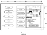
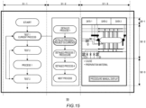
- Fig. 14 shows another example of the display unit 50.
- the display unit 50 is, for example, a monitor, a display, or the like.
- the display unit 50 may be the display of the tablet computer.
- the display unit 50 of the present example includes three display regions 51 (a display region 51-1, a display region 51-2, and a display region 51-3).
- a first flowchart shown in Fig. 11 is shown in the display region 51-1
- a second flowchart shown in Fig. 12 is shown in the display region 51-2.
- the flowchart shown in Fig. 13 may be further shown in the display region 51-2.
- the display region 51-3 shows the display region 52-1 to the display region 52-3 shown in Figs. 5 to 10 .
- steps S100 to S120 shown in Fig. 11 are shown in a simplified manner in the display region 51-1.
- a current process among the processes shown in the display region 51-1 may be indicated by a thick line frame.
- steps S200 to S230 shown in Fig. 12 are shown in a simplified manner in the display region 51-2.
- the detailed process of the current process in the display region 51-1 may be shown.
- a current process among the processes shown in the display region 51-1 may be indicated by a thick line frame.
- Fig. 14 is an example of a display manner of the display unit 50 in a case where the determination result acquisition unit 40 (see Fig. 4 ) acquires the determination result 41 that it is determined that the electrolytic apparatus 200 (see Fig. 1 ) is currently in the second state S2 (normal state) and in a case where predetermined work by the operator is required in the next process.
- Fig. 15 shows another example of the display unit 50.
- Fig. 15 is an example of the display by the display unit 50 when a trouble currently occurs in the electrolytic apparatus 200.
- a button for causing a procedure manual which is a procedure manual for coping with the trouble and indicates the procedure of the work by the operator to be displayed may be displayed in the display region 51-3 in the display region 52-3.
- Fig. 16 shows an example of the operation support system 300 according to one embodiment of the present invention.
- the operation support system 300 includes the operation support device 100 and the electrolytic apparatus 200.
- the instrument information acquisition unit 10 in the operation support device 100 acquires the instrument information 12 from the instrument 11 of the electrolytic apparatus 200.
- the switching portion information acquisition unit 20 in the operation support device 100 acquires the switching portion information 21 indicating the information regarding the switching portion 66 included in the electrolytic apparatus 200.
- the electrolytic apparatus state acquisition unit 30 in the operation support device 100 acquires the electrolytic apparatus state information 31 indicating the state of the electrolytic apparatus 200.
- the blocks may represent (1) a stage of a process in which an operation is performed or (2) a section of a device that is responsible for performing the operation.
- Specific stages may be implemented by a dedicated circuit, a programmable circuit, or a processor. Specific sections may be implemented by a dedicated circuit, a programmable circuit, or a processor. The programmable circuit and the processor may be supplied together with a computer-readable instruction. The computer-readable instruction may be stored on a computer-readable medium.
- the dedicated circuit may include at least one of a digital hardware circuit or an analog hardware circuit.
- the dedicated circuit may include at least one of an integrated circuit (IC) or a discrete circuit.
- the programmable circuit may include a hardware circuit for logical AND, logical OR, logical XOR, logical NAND, logical NOR, or other logical operations.
- the programmable circuit may include a reconfigurable hardware circuit which includes memory elements such as flip-flops, registers, field programmable gate arrays (FPGA), and programmable logic arrays (PLA), or the like.
- the computer-readable medium may include any tangible device capable of storing instructions for execution by an appropriate device.
- the computer-readable medium having instructions stored in the device includes a product including instructions that can be executed in order to create means for executing the operations designated in the flowcharts or block diagrams.
- the computer-readable medium may be, for example, an electronic storage medium, a magnetic storage medium, an optical storage medium, an electromagnetic storage medium, a semiconductor storage medium, and the like. More specifically, the computer-readable medium may be, for example, a floppy (registered trademark) disk, a diskette, a hard disk, a random access memory (RAM), a read-only memory (ROM), an erasable programmable read-only memory (EPROM or flash memory), an electrically erasable programmable read-only memory (EEPROM), a static random access memory (SRAM), a compact disc read-only memory (CD-ROM), a digital versatile disk (DVD), a Blu-Ray (registered trademark) disk, a memory stick, an integrated circuit card, or the like.
- a floppy (registered trademark) disk a diskette, a hard disk, a random access memory (RAM), a read-only memory (ROM), an erasable programmable read-only memory (EPROM or flash memory), an electrical
- the computer-readable instruction may include either of an assembler instruction, an instruction set architecture (ISA) instruction, a machine instruction, a machine dependent instruction, a microcode, a firmware instruction, state-setting data, a source code, or an object code.
- the source code and the object code may be written in any combination of one or more programming languages including an object oriented programming language and a conventional procedural programming language.
- the object oriented programming language may be Smalltalk (registered trademark), JAVA (registered trademark), C++, or the like.
- the procedural programming language may be a "C" programming language.
- the computer-readable instruction may be provided for a processor of a general-purpose computer, a special purpose computer, or another programmable data processing apparatus, or a programmable circuit locally or via a local area network (LAN) or a wide area network (WAN) such as the Internet.
- the processor of the general-purpose computer, the special purpose computer, or another programmable data processing apparatus, or the programmable circuit may execute the computer-readable instruction to create means for executing the operations designated in the flowcharts shown in Figs. 11 to 13 or block diagram shown in Fig. 4 .
- the processor may be a computer processor, a processing unit, a microprocessor, a digital signal processor, a controller, a microcontroller, or the like.
- Fig. 17 shows an example of a computer 2200 in which the operation support device 100 according to the embodiment of the present invention may be embodied in whole or in part.
- a program installed in the computer 2200 can cause the computer 2200 to function as an operation associated with the operation support device 100 according to the embodiment of the present invention or one or more sections of the operation support device 100, or can cause the operation or the one or more sections to be executed, or can cause the computer 2200 to execute each stage (see Figs. 11 to 13 ) according to the operation support method of the present invention.
- the program may be executed by a CPU 2212 to cause the computer 2200 to perform certain operations associated with some or all of the blocks in the flowcharts ( Figs. 11 to 13 ) and the block diagram ( Fig. 4 ) described in the present specification.
- the computer 2200 includes the CPU 2212, a RAM 2214, a graphic controller 2216, and a display device 2218.
- the CPU 2212, the RAM 2214, the graphic controller 2216, and the display device 2218 are mutually connected by a host controller 2210.
- the computer 2200 further includes an input/output unit such as a communication interface 2222, a hard disk drive 2224, a DVD-ROM drive 2226, and an IC card drive.
- the communication interface 2222, the hard disk drive 2224, the DVD-ROM drive 2226, the IC card drive, and the like are connected to the host controller 2210 via an input/output controller 2220.
- the computer further includes a legacy input/output unit such as a ROM 2230 and a keyboard 2242.
- the ROM 2230, the keyboard 2242, and the like are connected to the input/output controller 2220 via an input/output chip 2240.
- the CPU 2212 operates according to the programs stored in the ROM 2230 and the RAM 2214, thereby controlling each unit.
- the graphics controller 2216 acquires the image data generated by the CPU 2212 in a frame buffer or the like provided in the RAM 2214 or in the RAM 2214 and causes the image data to be displayed on the display device 2218.
- the ROM 2230 stores a boot programs or the like executed by the computer 2200 at the time of activation or a program depending on the hardware of the computer 2200.
- the input/output chip 2240 may also connect various input/output units to the input/output controller 2220 via a parallel port, a serial port, a keyboard port, a mouse port, or the like.
- the program is provided by a computer-readable medium such as the DVD-ROM 2201 or the IC card.
- the program is read from a computer-readable medium, installed in the hard disk drive 2224, the RAM 2214, or the ROM 2230 which is also an example of the computer-readable medium, and executed by the CPU 2212.
- the information processing described in these programs is read by the computer 2200 and provides cooperation between the programs and various types of hardware resources.
- the device or method may be configured by implementing operations or processing of information according to use of the computer 2200.
- the CPU 2212 may execute a communication program loaded in the RAM 2214 and instruct the communication interface 2222 to perform communication processing based on the processing described in the communication program.
- the communication interface 2222 reads transmission data stored in a transmission buffer processing area provided in a recording medium such as the RAM 2214, the hard disk drive 2224, the DVD-ROM 2201, or the IC card, transmits the read transmission data to the network, or writes reception data received from the network in a reception buffer processing area or the like provided on the recording medium.
- the CPU 2212 may cause the RAM 2214 to read all or a necessary portion of a file or a database stored in an external recording medium such as the hard disk drive 2224, the DVD-ROM drive 2226 (DVD-ROM 2201), or the IC card.
- the CPU 2212 may execute various types of processing on data on the RAM 2214. Next, the CPU 2212 may write back the processed data to the external recording medium.
- the CPU 2212 may execute various types of processing, which is described in the present disclosure and includes various types of operations designated by an instruction sequence of a program, information processing, condition determination, conditional branching, unconditional branching, information retrieval/replacement, and the like, on the data read from the RAM 2214.
- the CPU 2212 may writes back the results to the RAM 2214.
- the programs or software modules described above may be stored in a computer-readable medium on the computer 2200 or near the computer 2200.
- a recording medium such as a hard disk or a RAM provided in a server system connected to a dedicated communication network or the Internet can be used as the computer-readable medium.
- the program may be provided to the computer 2200 by the recording medium.
Landscapes
- Chemical & Material Sciences (AREA)
- Engineering & Computer Science (AREA)
- Metallurgy (AREA)
- Organic Chemistry (AREA)
- Chemical Kinetics & Catalysis (AREA)
- Electrochemistry (AREA)
- Materials Engineering (AREA)
- Automation & Control Theory (AREA)
- Analytical Chemistry (AREA)
- Inorganic Chemistry (AREA)
- Electrolytic Production Of Non-Metals, Compounds, Apparatuses Therefor (AREA)
- Electrophonic Musical Instruments (AREA)
- Input Circuits Of Receivers And Coupling Of Receivers And Audio Equipment (AREA)
- Supplying Of Containers To The Packaging Station (AREA)
- Water Treatment By Electricity Or Magnetism (AREA)
Claims (13)
- Betriebsunterstützungsverfahren einer Elektrolyseeinrichtung (200), das Betriebsunterstützungsverfahren umfassend:Erfassen von Instrumenteninformationen (12) durch eine Instrumenteninformationserfassungseinheit (10) von einem Instrument (11), das in der Elektrolyseeinrichtung (200) eingeschlossen ist einschließlich Messdaten, die Messdaten des Instruments (11) sind und durch Messung eines Parameters bezüglich der Elektrolyseeinrichtung (200) erhalten werden;Erfassen, durch eine Schaltabschnittinformationserfassungseinheit (20) Schaltabschnittsinformationen (21), die Informationen über einen oder mehrere Schaltabschnitte (66) anzeigen, die in der Elektrolyseeinrichtung (200) eingeschlossen sind und konfiguriert sind, um mindestens eine Durchflussrate eines Fluids (70, 71, 72, 73, 74, 75, 76) oder einen Gasdruck (77, 79) zu steuern;Erfassen, durch eine Elektrolyseeinrichtungzustandserfassungseinheit (30), von Elektrolyseeinrichtungszustandsinformationen (31), die einen Zustand der Elektrolyseeinrichtung (200) auf der Grundlage von mindestens einer der Instrumenteninformationen (12) oder der Schaltabschnittinformationen (21) anzeigen;Erfassen eines Bestimmungsergebnisses (41) durch eine Bestimmungsergebniserfassungseinheit (40), wenn die Elektrolyseeinrichtungszustandsinformationen (31) in einem vorbestimmten zweiten Zustand (C2) sind, dass bestimmt wird, dass der Zustand der Elektrolyseeinrichtung (200) ein zweiter Zustand (S2) ist, wobei der zweite Zustand (S2) ein Zustand ist, in dem eine Steuereinheit (60) den Schaltabschnitt (66) automatisch steuert; undAnzeigen, durch die Steuereinheit (60), der Elektrolyseeinrichtungszustandsinformationen (31), die bei der Erfassung des Zustands der Elektrolyseeinrichtung erfasst wurden, und des Bestimmungsergebnisses (41), das bei der Erfassung des Bestimmungsergebnisses (41) erfasst wurde, wobei das Erfassen des Bestimmungsergebnisses (41) ein Schritt ist, bei dem die Bestimmungsergebniserfassungseinheit (40) ein Bestimmungsergebnis (41) erfasst, das durch die Bestimmung erhalten wird, dass der Zustand der Elektrolyseeinrichtung (200) ein erster Zustand (S1) ist, wobei die Steuereinheit (60) eine Arbeit durch einen Bediener veranlassen soll, wenn die Elektrolyseeinrichtungszustandsinformation (31) in einem vorbestimmten ersten Zustand (C1) ist, der sich von dem zweiten Zustand (C2) unterscheidet, oder ein Bestimmungsergebnis (41), das durch Bestimmen erhalten wird, dass der Zustand der Elektrolyseeinrichtung (200) der zweite Zustand (S2) ist, wenn die Elektrolyseeinrichtungszustandsinformation (31) in dem zweiten Zustand (C2) ist,wobei die zweite Bedingung (C2) einem vorgegebenen Standard (Std) genügt.
- Betriebsunterstützungsverfahren nach Anspruch 1, wobei die Elektrolyseeinrichtungszustandsinformationen (31) Informationen einschließen, die anzeigen, dass sich die Elektrolyseeinrichtung (200) in einem normalen oder einem anormalen Zustand befindet, oder Prozessinformationen, die anzeigen, in welchem Prozess sich die Elektrolyseeinrichtung (200) befindet, undder erste Zustand (S1) einen Fall einschließt, in dem sich die Elektrolyseeinrichtung (200) im Normalzustand befindet, und einen Fall, in dem sich die Elektrolyseeinrichtung (200) im anormalen Zustand befindet,wobei der anormale Zustand ein Zustand ist, in dem die Elektrolyseeinrichtung (200) aufgrund des Auftretens einer Anomalie in der Elektrolyseeinrichtung (200) nicht automatisch gesteuert wird.
- Betriebsunterstützungsverfahren nach Anspruch 1 oder 2, wobei das Anzeigen ein Schritt ist, bei dem die Steuereinheit (60) die Elektrolyseeinrichtungszustandsinformationen (31) und das Bestimmungsergebnis (41) anzeigt, das durch die Bestimmung erhalten wird, dass der Zustand der Elektrolyseeinrichtung (200) der erste Zustand (S1) ist, oder das Bestimmungsergebnis (41), das durch die Bestimmung erhalten wird, dass der Zustand der Elektrolyseeinrichtung (200) der zweite Zustand (S2) ist.
- Betriebsunterstützungsverfahren nach Anspruch 3, wobei das Anzeigen ein Schritt ist, bei dem die Steuereinheit (60) eine Anzeigeeinheit (50) steuert, um die Elektrolyseeinrichtungszustandsinformationen (31) und das Bestimmungsergebnis (41), das durch die Bestimmung erhalten wird, dass der Zustand der Elektrolyseeinrichtung (200) der erste Zustand (S1) ist, oder das Bestimmungsergebnis (41), das durch die Bestimmung erhalten wird, dass der Zustand der Elektrolyseeinrichtung (200) der zweite Zustand (S2) ist, anzuzeigen.
- Betriebsunterstützungsverfahren nach einem der Ansprüche 1 bis 4, wobei die Arbeit des Bedieners mindestens eines einschließt aus einer manuellen Manipulation eines manuellen Manipulationszielschaltabschnitts (660), für den der Bediener den Schaltabschnitt (66) manuell manipuliert, einer Bestätigung für die Elektrolyseeinrichtung (200) oder einer Bestätigung für Komponenten der Elektrolyseeinrichtung (200).
- Betriebsunterstützungsverfahren nach Anspruch 5, wobei die Steuereinheit (60) konfiguriert ist, um den manuellen Manipulationszielschaltabschnitt (660), für den der Bediener den Schaltabschnitt (66) manuell manipuliert, und einen oder mehrere automatische Steuerungsziel-Schaltabschnitte (66), die Ziele der automatischen Steuerung in der Elektrolyseeinrichtung (200) sind, separat anzuzeigen.
- Betriebsunterstützungsverfahren nach Anspruch 6, wobei das Anzeigen weiter das Anzeigen einer Manipulationsreihenfolge des manuellen Manipulationszielschaltabschnitts (660) durch die Steuereinheit (60) einschließt.
- Betriebsunterstützungsverfahren nach Anspruch 7, wobei das Anzeigen weiter das Anzeigen eines Manipulationsziels einschließt, bei dem die Steuereinheit den manuellen Manipulationszielschaltabschnitt (660), der ein aktuelles Manipulationsziel ist, auf der Grundlage der Manipulationsreihenfolge sequentiell anzeigt.
- Betriebsunterstützungsverfahren nach Anspruch 7 oder 8, weiter umfassend, wenn die Bestimmungsergebniserfassungseinheit (40) ein Bestimmungsergebnis (41) erfasst, dass bestimmt wird, dass der Zustand der Elektrolyseeinrichtung (200) ein anormaler Zustand ist, bei der Erfassung des Bestimmungsergebnisses, Verriegeln von mindestens einem der Schaltabschnitte (66) durch die Steuereinheit (60), so dass er sich in einem festen Zustand befindet, nicht manipulierbar ist oder nicht geöffnet werden kann.
- Betriebsunterstützungsverfahren nach Anspruch 9, wobei, wenn die Steuereinheit (60) mindestens einen der einen oder mehreren Schaltabschnitte (66) in der Verriegelung verriegelt, die Steuereinheit (60) konfiguriert ist, um den Schaltabschnitt (66), der so eingestellt ist, dass er sich im festen Zustand befindet, getrennt von anderen Schaltabschnitten (66) als nicht manipulierbar oder nicht zu öffnen anzuzeigen.
- Betriebsunterstützungsprogramm, das einen Computer dazu veranlasst, das Verfahren zur Unterstützung von Operationen gemäß einem der Ansprüche 1 bis 10 auszuführen.
- Betriebsunterstützungsvorrichtung (100) zum Unterstützen des Betriebs einer Elektrolyseeinrichtung (200), die Betriebsunterstützungsvorrichtung (100) umfassend:eine Instrumenteninformationserfassungseinheit (10), die konfiguriert ist, um von einem in der Elektrolyseeinrichtung (200) eingeschlossenen Instrument (11) Instrumenteninformationen (12) zu erfassen einschließlich Messdaten, die Messdaten des Instruments (11) sind und durch Messung eines Parameters bezüglich der Elektrolyseeinrichtung (200) erhalten werden;eine Schaltabschnittinformationserfassungseinheit (20), die konfiguriert ist, um Schaltabschnittsinformationen (21) zu erfassen, die Informationen über einen oder mehrere Schaltabschnitte (66) anzeigen, die in der Elektrolyseeinrichtung (200) eingeschlossen sind, und konfiguriert ist, um mindestens eine Durchflussrate eines Fluids (70, 71, 72, 73, 74, 75, 76) oder einen Gasdruck (77, 79) zu steuern;eine Elektrolyseeinrichtungszustandserfassungseinheit (30), die konfiguriert ist, um Elektrolyseeinrichtungszustandsinformationen (31) zu erfassen, die einen Zustand der Elektrolyseeinrichtung (200) auf der Grundlage von mindestens einer der Instrumenteninformationen (12) oder der Schaltabschnittinformationen (21) anzeigen;eine Bestimmungsergebniserfassungseinheit (40), die konfiguriert ist, um, wenn sich die Elektrolyseeinrichtungszustandsinformationen (31) in einem vorbestimmten zweiten Zustand (C2) befinden, ein Bestimmungsergebnis (41) erfasst, dass bestimmt wird, dass der Zustand der Elektrolyseeinrichtung (200) ein zweiter Zustand (S2) ist, wobei der zweite Zustand (S2) ein Zustand ist, in dem eine Steuereinheit (60) den Schaltabschnitt (66) automatisch steuert; unddie Steuereinheit (60) konfiguriert ist, um die von der Elektrolyseeinrichtungszustandserfassungseinheit (30) erfassten Elektrolyseeinrichtungszustandsinformationen (31) und das von der Bestimmungsergebniserfassungseinheit (40) erfasste Bestimmungsergebnis (41) anzuzeigen, wobei die Bestimmungsergebniserfassungseinheit (40) konfiguriert ist, um ein Bestimmungsergebnis (41) zu erfassen, das durch die Bestimmung erhalten wird, dass der Zustand der Elektrolyseeinrichtung (200) ein erster Zustand (S1) ist, wobei die Steuereinheit (60) eine Arbeit durch einen Bediener veranlassen soll, wenn die Elektrolyseeinrichtungszustandsinformationen (31) in einem vorbestimmten ersten Zustand (C1) sind, der sich von dem zweiten Zustand (C2) unterscheidet, oder ein Bestimmungsergebnis (41), das durch die Bestimmung erhalten wird, dass der Zustand der Elektrolyseeinrichtung (200) der zweite Zustand (S2) ist, wenn die Elektrolyseeinrichtungszustandsinformationen (31) im zweiten Zustand (C2) sind,wobei die zweite Bedingung (C2) einem vorgegebenen Standard (Std) genügt.
- Betriebsunterstützungsvorrichtung nach Anspruch 12, wobei die Elektrolyseeinrichtungszustandsinformationen (31) Informationen einschließen, die anzeigen, dass sich die Elektrolyseeinrichtung (200) in einem normalen oder einem anormalen Zustand befindet, oder Prozessinformationen, die anzeigen, in welchem Prozess sich die Elektrolyseeinrichtung (200) befindet, undder erste Zustand (S1) einen Fall einschließt, in dem sich die Elektrolyseeinrichtung (200) im Normalzustand befindet, und einen Fall, in dem sich die Elektrolyseeinrichtung (200) im anormalen Zustand befindet,wobei der anormale Zustand ein Zustand ist, in dem die Elektrolyseeinrichtung (200) aufgrund des Auftretens einer Anomalie in der Elektrolyseeinrichtung (200) nicht automatisch gesteuert wird.
Applications Claiming Priority (2)
| Application Number | Priority Date | Filing Date | Title |
|---|---|---|---|
| JP2020121700 | 2020-07-15 | ||
| PCT/JP2021/021467 WO2022014197A1 (ja) | 2020-07-15 | 2021-06-04 | 運転支援方法、運転支援装置、運転支援システムおよび運転支援プログラム |
Publications (3)
| Publication Number | Publication Date |
|---|---|
| EP4183899A1 EP4183899A1 (de) | 2023-05-24 |
| EP4183899A4 EP4183899A4 (de) | 2024-07-31 |
| EP4183899B1 true EP4183899B1 (de) | 2025-04-30 |
Family
ID=79555177
Family Applications (1)
| Application Number | Title | Priority Date | Filing Date |
|---|---|---|---|
| EP21843512.1A Active EP4183899B1 (de) | 2020-07-15 | 2021-06-04 | Betriebsunterstützungsverfahren, betriebsunterstützungsvorrichtung, betriebsunterstützungssystem und betriebsunterstützungsprogramm |
Country Status (8)
| Country | Link |
|---|---|
| US (1) | US12571117B2 (de) |
| EP (1) | EP4183899B1 (de) |
| JP (1) | JP7169491B2 (de) |
| KR (1) | KR102887564B1 (de) |
| CN (2) | CN117230486A (de) |
| AU (1) | AU2021309310B2 (de) |
| CA (1) | CA3185261A1 (de) |
| WO (1) | WO2022014197A1 (de) |
Families Citing this family (1)
| Publication number | Priority date | Publication date | Assignee | Title |
|---|---|---|---|---|
| CN117230486A (zh) | 2020-07-15 | 2023-12-15 | 旭化成株式会社 | 运转支援方法、运转支援装置、运转支援系统和存储介质 |
Family Cites Families (15)
| Publication number | Priority date | Publication date | Assignee | Title |
|---|---|---|---|---|
| JPH06190366A (ja) * | 1992-12-25 | 1994-07-12 | Funai Electric Co Ltd | イオン水生成器 |
| JP3411094B2 (ja) * | 1994-05-09 | 2003-05-26 | ホシザキ電機株式会社 | 塩水供給装置 |
| US6591199B2 (en) | 2000-04-11 | 2003-07-08 | Recherche 2000 Inc. | Method and system for acquisition, monitoring, display and diagnosis of operational parameters of electrolyzers |
| JP3725145B2 (ja) * | 2003-07-14 | 2005-12-07 | 東洋炭素株式会社 | 溶融塩電解浴の制御装置及びその制御方法 |
| JP4727332B2 (ja) | 2005-07-22 | 2011-07-20 | 三菱重工業株式会社 | 水電解装置の運転制御方法およびその装置 |
| JP4696276B2 (ja) * | 2007-09-19 | 2011-06-08 | 本田技研工業株式会社 | 電解水生成方法及び装置 |
| JP5524261B2 (ja) | 2012-03-19 | 2014-06-18 | 中国電力株式会社 | 電解装置の制御装置及び冬期運用方法 |
| US9834846B2 (en) | 2015-06-19 | 2017-12-05 | The Boeing Company | System and method for transitioning a reversible solid oxide fuel cell system between generation and electrolysis modes |
| CN107059052B (zh) * | 2017-02-10 | 2019-01-04 | 中南大学 | 一种铜电解车间电解槽内状态自动转换方法及其系统 |
| JP2018131647A (ja) | 2017-02-14 | 2018-08-23 | 東京瓦斯株式会社 | 電気分解システム、制御装置、及びプログラム |
| JP2019167564A (ja) * | 2018-03-22 | 2019-10-03 | 住友金属鉱山株式会社 | 電解設備 |
| JP7366033B2 (ja) * | 2018-09-06 | 2023-10-20 | 住友重機械工業株式会社 | 支援装置、支援方法、支援プログラム、及び、ボイラシステム |
| JP7345086B2 (ja) | 2018-12-17 | 2023-09-15 | パナソニックIpマネジメント株式会社 | 電解水散布装置及び送風装置 |
| US11339488B2 (en) * | 2019-02-19 | 2022-05-24 | Achínibahjeechin Intellectual Property, LLC | System and method for controlling a multi-state electrochemical cell |
| CN117230486A (zh) | 2020-07-15 | 2023-12-15 | 旭化成株式会社 | 运转支援方法、运转支援装置、运转支援系统和存储介质 |
-
2021
- 2021-06-04 CN CN202311185630.6A patent/CN117230486A/zh active Pending
- 2021-06-04 EP EP21843512.1A patent/EP4183899B1/de active Active
- 2021-06-04 AU AU2021309310A patent/AU2021309310B2/en active Active
- 2021-06-04 WO PCT/JP2021/021467 patent/WO2022014197A1/ja not_active Ceased
- 2021-06-04 JP JP2022536171A patent/JP7169491B2/ja active Active
- 2021-06-04 CN CN202180034246.9A patent/CN115516138A/zh active Pending
- 2021-06-04 CA CA3185261A patent/CA3185261A1/en active Pending
- 2021-06-04 KR KR1020227030354A patent/KR102887564B1/ko active Active
-
2022
- 2022-11-03 US US17/980,501 patent/US12571117B2/en active Active
Also Published As
| Publication number | Publication date |
|---|---|
| US12571117B2 (en) | 2026-03-10 |
| CN115516138A (zh) | 2022-12-23 |
| EP4183899A1 (de) | 2023-05-24 |
| KR20220136404A (ko) | 2022-10-07 |
| JPWO2022014197A1 (de) | 2022-01-20 |
| US20230047541A1 (en) | 2023-02-16 |
| JP7169491B2 (ja) | 2022-11-10 |
| CN117230486A (zh) | 2023-12-15 |
| AU2021309310B2 (en) | 2024-02-01 |
| CA3185261A1 (en) | 2022-01-20 |
| KR102887564B1 (ko) | 2025-11-17 |
| EP4183899A4 (de) | 2024-07-31 |
| AU2021309310A1 (en) | 2023-01-19 |
| WO2022014197A1 (ja) | 2022-01-20 |
Similar Documents
| Publication | Publication Date | Title |
|---|---|---|
| US11220755B2 (en) | Apparatus for alkaline water electrolysis, and gas production method | |
| US12571117B2 (en) | Operation support method, operation support device, operation support system, and operation support program | |
| US20070208519A1 (en) | Adaptive method and system of monitoring signals for detecting anomalies | |
| JP6609489B2 (ja) | 電解質分析装置 | |
| US20240229270A9 (en) | Analysis system, analysis method, and computer readable medium | |
| EP4036919B1 (de) | Computerimplementiertes verfahren, computerprogrammprodukt und system zur datenanalyse | |
| EP0727656A1 (de) | Methode zur Schätzung der Korrosion an strukturellem Material von Anlagen, und Korrosionsdiagnosesystem | |
| EP4435686B1 (de) | Betriebsunterstützungsvorrichtung, betriebsunterstützungsverfahren und betriebsunterstützungsprogramm | |
| KR20230151028A (ko) | 운전 지원 장치, 운전 지원 시스템, 운전 지원 방법 및 운전 지원 프로그램 | |
| JP7182025B1 (ja) | 運転支援装置、運転支援方法および運転支援プログラム | |
| JP2024049729A (ja) | 運転支援装置、運転支援方法および運転支援プログラム | |
| KR102967598B1 (ko) | 해석 시스템, 해석 방법 및 해석 프로그램 | |
| US5186798A (en) | Solution quantitative analysis apparatus, quantitative analysis methods, and nuclear reactor water quality control system | |
| JP7796228B2 (ja) | 運転支援装置、運転支援方法および運転支援プログラム | |
| EP4497849A1 (de) | Betriebsunterstützungsverfahren, betriebsunterstützungsvorrichtung, betriebsunterstützungssystem und betriebsunterstützungsprogramm | |
| Liu et al. | Operating performance assessment for dynamic industrial processes based on CVA-TPLS | |
| JP4690947B2 (ja) | 異常対処方法、異常対処装置および荷電粒子線装置 | |
| JP2001141722A (ja) | プラント構造材料の腐食推定方法、および腐食診断システム |
Legal Events
| Date | Code | Title | Description |
|---|---|---|---|
| STAA | Information on the status of an ep patent application or granted ep patent |
Free format text: STATUS: THE INTERNATIONAL PUBLICATION HAS BEEN MADE |
|
| PUAI | Public reference made under article 153(3) epc to a published international application that has entered the european phase |
Free format text: ORIGINAL CODE: 0009012 |
|
| STAA | Information on the status of an ep patent application or granted ep patent |
Free format text: STATUS: REQUEST FOR EXAMINATION WAS MADE |
|
| 17P | Request for examination filed |
Effective date: 20230110 |
|
| AK | Designated contracting states |
Kind code of ref document: A1 Designated state(s): AL AT BE BG CH CY CZ DE DK EE ES FI FR GB GR HR HU IE IS IT LI LT LU LV MC MK MT NL NO PL PT RO RS SE SI SK SM TR |
|
| DAV | Request for validation of the european patent (deleted) | ||
| DAX | Request for extension of the european patent (deleted) | ||
| STAA | Information on the status of an ep patent application or granted ep patent |
Free format text: STATUS: EXAMINATION IS IN PROGRESS |
|
| A4 | Supplementary search report drawn up and despatched |
Effective date: 20240702 |
|
| RIC1 | Information provided on ipc code assigned before grant |
Ipc: C25B 15/023 20210101ALI20240627BHEP Ipc: C25B 1/46 20060101AFI20240627BHEP |
|
| 17Q | First examination report despatched |
Effective date: 20240712 |
|
| GRAP | Despatch of communication of intention to grant a patent |
Free format text: ORIGINAL CODE: EPIDOSNIGR1 |
|
| STAA | Information on the status of an ep patent application or granted ep patent |
Free format text: STATUS: GRANT OF PATENT IS INTENDED |
|
| INTG | Intention to grant announced |
Effective date: 20241218 |
|
| GRAS | Grant fee paid |
Free format text: ORIGINAL CODE: EPIDOSNIGR3 |
|
| GRAA | (expected) grant |
Free format text: ORIGINAL CODE: 0009210 |
|
| STAA | Information on the status of an ep patent application or granted ep patent |
Free format text: STATUS: THE PATENT HAS BEEN GRANTED |
|
| P01 | Opt-out of the competence of the unified patent court (upc) registered |
Free format text: CASE NUMBER: APP_13387/2025 Effective date: 20250318 |
|
| AK | Designated contracting states |
Kind code of ref document: B1 Designated state(s): AL AT BE BG CH CY CZ DE DK EE ES FI FR GB GR HR HU IE IS IT LI LT LU LV MC MK MT NL NO PL PT RO RS SE SI SK SM TR |
|
| REG | Reference to a national code |
Ref country code: CH Ref legal event code: EP Ref country code: GB Ref legal event code: FG4D |
|
| P01 | Opt-out of the competence of the unified patent court (upc) registered |
Free format text: CASE NUMBER: APP_13387/2025 Effective date: 20250318 |
|
| REG | Reference to a national code |
Ref country code: IE Ref legal event code: FG4D |
|
| REG | Reference to a national code |
Ref country code: DE Ref legal event code: R096 Ref document number: 602021030146 Country of ref document: DE |
|
| REG | Reference to a national code |
Ref country code: NL Ref legal event code: FP |
|
| PGFP | Annual fee paid to national office [announced via postgrant information from national office to epo] |
Ref country code: NL Payment date: 20250526 Year of fee payment: 5 |
|
| PGFP | Annual fee paid to national office [announced via postgrant information from national office to epo] |
Ref country code: DE Payment date: 20250528 Year of fee payment: 5 |
|
| PGFP | Annual fee paid to national office [announced via postgrant information from national office to epo] |
Ref country code: GB Payment date: 20250522 Year of fee payment: 5 |
|
| PGFP | Annual fee paid to national office [announced via postgrant information from national office to epo] |
Ref country code: FR Payment date: 20250523 Year of fee payment: 5 |
|
| PGFP | Annual fee paid to national office [announced via postgrant information from national office to epo] |
Ref country code: AT Payment date: 20250721 Year of fee payment: 5 |
|
| REG | Reference to a national code |
Ref country code: AT Ref legal event code: MK05 Ref document number: 1790087 Country of ref document: AT Kind code of ref document: T Effective date: 20250430 |
|
| PG25 | Lapsed in a contracting state [announced via postgrant information from national office to epo] |
Ref country code: FI Free format text: LAPSE BECAUSE OF FAILURE TO SUBMIT A TRANSLATION OF THE DESCRIPTION OR TO PAY THE FEE WITHIN THE PRESCRIBED TIME-LIMIT Effective date: 20250430 Ref country code: PT Free format text: LAPSE BECAUSE OF FAILURE TO SUBMIT A TRANSLATION OF THE DESCRIPTION OR TO PAY THE FEE WITHIN THE PRESCRIBED TIME-LIMIT Effective date: 20250901 Ref country code: ES Free format text: LAPSE BECAUSE OF FAILURE TO SUBMIT A TRANSLATION OF THE DESCRIPTION OR TO PAY THE FEE WITHIN THE PRESCRIBED TIME-LIMIT Effective date: 20250430 |
|
| REG | Reference to a national code |
Ref country code: LT Ref legal event code: MG9D |
|
| PG25 | Lapsed in a contracting state [announced via postgrant information from national office to epo] |
Ref country code: GR Free format text: LAPSE BECAUSE OF FAILURE TO SUBMIT A TRANSLATION OF THE DESCRIPTION OR TO PAY THE FEE WITHIN THE PRESCRIBED TIME-LIMIT Effective date: 20250731 Ref country code: NO Free format text: LAPSE BECAUSE OF FAILURE TO SUBMIT A TRANSLATION OF THE DESCRIPTION OR TO PAY THE FEE WITHIN THE PRESCRIBED TIME-LIMIT Effective date: 20250730 |
|
| PG25 | Lapsed in a contracting state [announced via postgrant information from national office to epo] |
Ref country code: PL Free format text: LAPSE BECAUSE OF FAILURE TO SUBMIT A TRANSLATION OF THE DESCRIPTION OR TO PAY THE FEE WITHIN THE PRESCRIBED TIME-LIMIT Effective date: 20250430 |
|
| PG25 | Lapsed in a contracting state [announced via postgrant information from national office to epo] |
Ref country code: BG Free format text: LAPSE BECAUSE OF FAILURE TO SUBMIT A TRANSLATION OF THE DESCRIPTION OR TO PAY THE FEE WITHIN THE PRESCRIBED TIME-LIMIT Effective date: 20250430 |
|
| PG25 | Lapsed in a contracting state [announced via postgrant information from national office to epo] |
Ref country code: HR Free format text: LAPSE BECAUSE OF FAILURE TO SUBMIT A TRANSLATION OF THE DESCRIPTION OR TO PAY THE FEE WITHIN THE PRESCRIBED TIME-LIMIT Effective date: 20250430 |
|
| PG25 | Lapsed in a contracting state [announced via postgrant information from national office to epo] |
Ref country code: AT Free format text: LAPSE BECAUSE OF FAILURE TO SUBMIT A TRANSLATION OF THE DESCRIPTION OR TO PAY THE FEE WITHIN THE PRESCRIBED TIME-LIMIT Effective date: 20250430 |
|
| PG25 | Lapsed in a contracting state [announced via postgrant information from national office to epo] |
Ref country code: RS Free format text: LAPSE BECAUSE OF FAILURE TO SUBMIT A TRANSLATION OF THE DESCRIPTION OR TO PAY THE FEE WITHIN THE PRESCRIBED TIME-LIMIT Effective date: 20250731 |
|
| PG25 | Lapsed in a contracting state [announced via postgrant information from national office to epo] |
Ref country code: IS Free format text: LAPSE BECAUSE OF FAILURE TO SUBMIT A TRANSLATION OF THE DESCRIPTION OR TO PAY THE FEE WITHIN THE PRESCRIBED TIME-LIMIT Effective date: 20250830 |
|
| PG25 | Lapsed in a contracting state [announced via postgrant information from national office to epo] |
Ref country code: LV Free format text: LAPSE BECAUSE OF FAILURE TO SUBMIT A TRANSLATION OF THE DESCRIPTION OR TO PAY THE FEE WITHIN THE PRESCRIBED TIME-LIMIT Effective date: 20250430 |
|
| PG25 | Lapsed in a contracting state [announced via postgrant information from national office to epo] |
Ref country code: SM Free format text: LAPSE BECAUSE OF FAILURE TO SUBMIT A TRANSLATION OF THE DESCRIPTION OR TO PAY THE FEE WITHIN THE PRESCRIBED TIME-LIMIT Effective date: 20250430 Ref country code: DK Free format text: LAPSE BECAUSE OF FAILURE TO SUBMIT A TRANSLATION OF THE DESCRIPTION OR TO PAY THE FEE WITHIN THE PRESCRIBED TIME-LIMIT Effective date: 20250430 |
|
| PG25 | Lapsed in a contracting state [announced via postgrant information from national office to epo] |
Ref country code: CZ Free format text: LAPSE BECAUSE OF FAILURE TO SUBMIT A TRANSLATION OF THE DESCRIPTION OR TO PAY THE FEE WITHIN THE PRESCRIBED TIME-LIMIT Effective date: 20250430 |
|
| PG25 | Lapsed in a contracting state [announced via postgrant information from national office to epo] |
Ref country code: EE Free format text: LAPSE BECAUSE OF FAILURE TO SUBMIT A TRANSLATION OF THE DESCRIPTION OR TO PAY THE FEE WITHIN THE PRESCRIBED TIME-LIMIT Effective date: 20250430 |
|
| PG25 | Lapsed in a contracting state [announced via postgrant information from national office to epo] |
Ref country code: SK Free format text: LAPSE BECAUSE OF FAILURE TO SUBMIT A TRANSLATION OF THE DESCRIPTION OR TO PAY THE FEE WITHIN THE PRESCRIBED TIME-LIMIT Effective date: 20250430 |
|
| REG | Reference to a national code |
Ref country code: CH Ref legal event code: H13 Free format text: ST27 STATUS EVENT CODE: U-0-0-H10-H13 (AS PROVIDED BY THE NATIONAL OFFICE) Effective date: 20260127 |
|
| PG25 | Lapsed in a contracting state [announced via postgrant information from national office to epo] |
Ref country code: IT Free format text: LAPSE BECAUSE OF FAILURE TO SUBMIT A TRANSLATION OF THE DESCRIPTION OR TO PAY THE FEE WITHIN THE PRESCRIBED TIME-LIMIT Effective date: 20250430 |
|
| PG25 | Lapsed in a contracting state [announced via postgrant information from national office to epo] |
Ref country code: MC Free format text: LAPSE BECAUSE OF FAILURE TO SUBMIT A TRANSLATION OF THE DESCRIPTION OR TO PAY THE FEE WITHIN THE PRESCRIBED TIME-LIMIT Effective date: 20250430 |
|
| REG | Reference to a national code |
Ref country code: DE Ref legal event code: R097 Ref document number: 602021030146 Country of ref document: DE |
|
| PG25 | Lapsed in a contracting state [announced via postgrant information from national office to epo] |
Ref country code: LU Free format text: LAPSE BECAUSE OF NON-PAYMENT OF DUE FEES Effective date: 20250604 |
|
| REG | Reference to a national code |
Ref country code: BE Ref legal event code: MM Effective date: 20250630 |
|
| PG25 | Lapsed in a contracting state [announced via postgrant information from national office to epo] |
Ref country code: RO Free format text: LAPSE BECAUSE OF FAILURE TO SUBMIT A TRANSLATION OF THE DESCRIPTION OR TO PAY THE FEE WITHIN THE PRESCRIBED TIME-LIMIT Effective date: 20250430 |
|
| PLBE | No opposition filed within time limit |
Free format text: ORIGINAL CODE: 0009261 |
|
| STAA | Information on the status of an ep patent application or granted ep patent |
Free format text: STATUS: NO OPPOSITION FILED WITHIN TIME LIMIT |
|
| REG | Reference to a national code |
Ref country code: CH Ref legal event code: L10 Free format text: ST27 STATUS EVENT CODE: U-0-0-L10-L00 (AS PROVIDED BY THE NATIONAL OFFICE) Effective date: 20260311 |
|
| 26N | No opposition filed |
Effective date: 20260202 |
|
| PG25 | Lapsed in a contracting state [announced via postgrant information from national office to epo] |
Ref country code: IE Free format text: LAPSE BECAUSE OF NON-PAYMENT OF DUE FEES Effective date: 20250604 |
|
| PG25 | Lapsed in a contracting state [announced via postgrant information from national office to epo] |
Ref country code: BE Free format text: LAPSE BECAUSE OF NON-PAYMENT OF DUE FEES Effective date: 20250630 |
|
| PG25 | Lapsed in a contracting state [announced via postgrant information from national office to epo] |
Ref country code: CH Free format text: LAPSE BECAUSE OF NON-PAYMENT OF DUE FEES Effective date: 20250630 |