EP4183545A1 - Körperteil aus kunststoff mit scheibenlaserschnitt - Google Patents
Körperteil aus kunststoff mit scheibenlaserschnitt Download PDFInfo
- Publication number
- EP4183545A1 EP4183545A1 EP21306602.0A EP21306602A EP4183545A1 EP 4183545 A1 EP4183545 A1 EP 4183545A1 EP 21306602 A EP21306602 A EP 21306602A EP 4183545 A1 EP4183545 A1 EP 4183545A1
- Authority
- EP
- European Patent Office
- Prior art keywords
- face
- flap
- plastic panel
- plastic
- panel
- Prior art date
- Legal status (The legal status is an assumption and is not a legal conclusion. Google has not performed a legal analysis and makes no representation as to the accuracy of the status listed.)
- Pending
Links
Images





Classifications
-
- B—PERFORMING OPERATIONS; TRANSPORTING
- B23—MACHINE TOOLS; METAL-WORKING NOT OTHERWISE PROVIDED FOR
- B23K—SOLDERING OR UNSOLDERING; WELDING; CLADDING OR PLATING BY SOLDERING OR WELDING; CUTTING BY APPLYING HEAT LOCALLY, e.g. FLAME CUTTING; WORKING BY LASER BEAM
- B23K26/00—Working by laser beam, e.g. welding, cutting or boring
- B23K26/36—Removing material
- B23K26/38—Removing material by boring or cutting
-
- B—PERFORMING OPERATIONS; TRANSPORTING
- B29—WORKING OF PLASTICS; WORKING OF SUBSTANCES IN A PLASTIC STATE IN GENERAL
- B29C—SHAPING OR JOINING OF PLASTICS; SHAPING OF MATERIAL IN A PLASTIC STATE, NOT OTHERWISE PROVIDED FOR; AFTER-TREATMENT OF THE SHAPED PRODUCTS, e.g. REPAIRING
- B29C45/00—Injection moulding, i.e. forcing the required volume of moulding material through a nozzle into a closed mould; Apparatus therefor
- B29C45/0017—Injection moulding, i.e. forcing the required volume of moulding material through a nozzle into a closed mould; Apparatus therefor moulding interconnected elements which are movable with respect to one another, e.g. chains or hinges
-
- B—PERFORMING OPERATIONS; TRANSPORTING
- B23—MACHINE TOOLS; METAL-WORKING NOT OTHERWISE PROVIDED FOR
- B23K—SOLDERING OR UNSOLDERING; WELDING; CLADDING OR PLATING BY SOLDERING OR WELDING; CUTTING BY APPLYING HEAT LOCALLY, e.g. FLAME CUTTING; WORKING BY LASER BEAM
- B23K26/00—Working by laser beam, e.g. welding, cutting or boring
- B23K26/36—Removing material
- B23K26/40—Removing material taking account of the properties of the material involved
- B23K26/402—Removing material taking account of the properties of the material involved involving non-metallic material, e.g. isolators
-
- B—PERFORMING OPERATIONS; TRANSPORTING
- B29—WORKING OF PLASTICS; WORKING OF SUBSTANCES IN A PLASTIC STATE IN GENERAL
- B29C—SHAPING OR JOINING OF PLASTICS; SHAPING OF MATERIAL IN A PLASTIC STATE, NOT OTHERWISE PROVIDED FOR; AFTER-TREATMENT OF THE SHAPED PRODUCTS, e.g. REPAIRING
- B29C45/00—Injection moulding, i.e. forcing the required volume of moulding material through a nozzle into a closed mould; Apparatus therefor
- B29C45/0046—Details relating to the filling pattern or flow paths or flow characteristics of moulding material in the mould cavity
-
- B—PERFORMING OPERATIONS; TRANSPORTING
- B29—WORKING OF PLASTICS; WORKING OF SUBSTANCES IN A PLASTIC STATE IN GENERAL
- B29C—SHAPING OR JOINING OF PLASTICS; SHAPING OF MATERIAL IN A PLASTIC STATE, NOT OTHERWISE PROVIDED FOR; AFTER-TREATMENT OF THE SHAPED PRODUCTS, e.g. REPAIRING
- B29C45/00—Injection moulding, i.e. forcing the required volume of moulding material through a nozzle into a closed mould; Apparatus therefor
- B29C45/0053—Injection moulding, i.e. forcing the required volume of moulding material through a nozzle into a closed mould; Apparatus therefor combined with a final operation, e.g. shaping
-
- B—PERFORMING OPERATIONS; TRANSPORTING
- B29—WORKING OF PLASTICS; WORKING OF SUBSTANCES IN A PLASTIC STATE IN GENERAL
- B29C—SHAPING OR JOINING OF PLASTICS; SHAPING OF MATERIAL IN A PLASTIC STATE, NOT OTHERWISE PROVIDED FOR; AFTER-TREATMENT OF THE SHAPED PRODUCTS, e.g. REPAIRING
- B29C45/00—Injection moulding, i.e. forcing the required volume of moulding material through a nozzle into a closed mould; Apparatus therefor
- B29C45/0053—Injection moulding, i.e. forcing the required volume of moulding material through a nozzle into a closed mould; Apparatus therefor combined with a final operation, e.g. shaping
- B29C45/0055—Shaping
- B29C2045/0058—Shaping removing material
-
- B—PERFORMING OPERATIONS; TRANSPORTING
- B29—WORKING OF PLASTICS; WORKING OF SUBSTANCES IN A PLASTIC STATE IN GENERAL
- B29C—SHAPING OR JOINING OF PLASTICS; SHAPING OF MATERIAL IN A PLASTIC STATE, NOT OTHERWISE PROVIDED FOR; AFTER-TREATMENT OF THE SHAPED PRODUCTS, e.g. REPAIRING
- B29C2793/00—Shaping techniques involving a cutting or machining operation
- B29C2793/0027—Cutting off
-
- B—PERFORMING OPERATIONS; TRANSPORTING
- B29—WORKING OF PLASTICS; WORKING OF SUBSTANCES IN A PLASTIC STATE IN GENERAL
- B29C—SHAPING OR JOINING OF PLASTICS; SHAPING OF MATERIAL IN A PLASTIC STATE, NOT OTHERWISE PROVIDED FOR; AFTER-TREATMENT OF THE SHAPED PRODUCTS, e.g. REPAIRING
- B29C2793/00—Shaping techniques involving a cutting or machining operation
- B29C2793/009—Shaping techniques involving a cutting or machining operation after shaping
-
- B—PERFORMING OPERATIONS; TRANSPORTING
- B29—WORKING OF PLASTICS; WORKING OF SUBSTANCES IN A PLASTIC STATE IN GENERAL
- B29L—INDEXING SCHEME ASSOCIATED WITH SUBCLASS B29C, RELATING TO PARTICULAR ARTICLES
- B29L2031/00—Other particular articles
- B29L2031/30—Vehicles, e.g. ships or aircraft, or body parts thereof
- B29L2031/3005—Body finishings
Definitions
- the invention relates to vehicle body part. More precisely, the invention is related to vehicle body parts intended to integrate at least one movable flap covering an opening and the method for producing such body parts.
- flap is meant any type of element that can perform a function of covering an opening of the body part, for example, a movable cover, flap, shutter.
- vehicle body part As an assembly of a molded plastic panel inside which an opening is designed, and a molded plastic flap designed to cover the opening.
- Plastic panels and flaps have been generally produced as two separate parts and are very complex to produce in terms of costs, color harmony and gap and flushness management. Indeed, current products require wide gaps or separate parts to realize flaps flushing the openings of plastic panels in proportions that meet the specifications of the car manufacturers.
- the invention relates to a method for producing a plastic body part for motor vehicles comprising the following steps:
- the method of the invention makes possible to realize a smooth-looking body part integrating a flap closing the opening of the plastic panel without any additional costs for separate injection tools.
- the method of the invention only requires one single injection molding step and the step of laser cutting of a portion of the plastic panel which integrated the projecting portion allows to cut a flap which is sized to be flush with the first face of the molded plastic panel.
- the flush arrangement between the first face of the flap and the first face of the plastic panel when the flap is in the closed position is optimized and meet the specifications of the car manufacturers.
- the thickness of the projecting portion with respect to the rest of the first face of the plastic panel is about 0.4 mm.
- the second face of the plastic panel comprises a recess opposed to the projecting portion, the recess having a corresponding shape to the shape of the projecting portion.
- the angle of the non-vertical cutting plane with respect to the first side of the plastic panel is between 40° and 60°.
- the plastic panel is molded with a groove having rounded upper edges on the first face of the plastic panel and deliming a surface of this first face, laser cutting taking place at the bottom of the groove while preserving the rounded profile of said upper edges.
- decorating stage it is understood any kind of decoration method of such elements known of the skilled person. It can be for example painting, digital printing, tampon printing, hot stamping, in mould labeling, foil application and even texturing by etching or laser.
- the rounded upper edges of the groove can define a closed surface, i.e. the groove extend all around the sides of the surface that will be laser cutting , or they can define an open surface, i.e. the groove does not extend all around the sides of said surface which remains linked to the first face of the plastic panel by at least one side.
- the groove prevents the formation of an unsightly excess of decorating coating (paint or other finish) along the edges delimiting the opening of the first face of plastic panel and the edges of the first face of the flap, when the first face of the plastic panel alone (if the decorating step takes place before laser cutting) or when both the first face of the plastic panel and the first face of the flap (if the decorating step takes place after laser cutting) receives a decorating coat (paint or other finish).
- the first face of the plastic panel is decorated before the step of laser cutting.
- the invention also relates to a plastic body part for motor vehicles comprising:
- plastic body part taken alone or in combination:
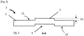
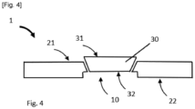
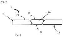
- Figures 1 to 10 show a plastic body part according to an embodiment and a variant, designated by the general reference 1.
- This plastic body part can be made according to a first production method or according to a variant of such a method.
- a plastic panel 2 is molded, such a plastic panel 2 having a first face 21 and a second face 22 opposed to the first face 21.
- the plastic panel 2 is molded with a projecting portion 3 of the first face.
- the projecting portion 3 is sized during the molding step.
- the plastic panel 2 is molded with a recess 4 in the second face 22 opposed to the projecting portion.
- the recess 4 having a corresponding shape to the shape of the projecting portion 3.
- Such a recess 4 ensures that the flap will not protrude below the second face of the plastic panel when the flap is in the closed position ( fig. 5 ), which may be preferable in some cases, with regard to the aerodynamic performance of the body part and with regard to final visual appearance requirements of the end-users.
- To have recess 4 having a corresponding shape to the shape of the projecting portion 3 allows to mold a part which has a constant thickness which improves the injection molding quality of the part.
- the laser cutting step of the plastic panel 2 is carried out in a non-vertical cutting plane locally with respect to the first face 21, forming an opening 10 and a flap 30 composed by the projecting portion 3 (see fig. 3 and 4 ).
- Cutting the first face 21 the plastic panel 2 according to a locally non-vertical cutting plane ensures optimum flushness between the first side 31 of the flap 30 and the first side 21 of the plastic panel 2 when the flap 30 is in the closed position.
- Such a flush quality is otherwise not possible with a vertical cutting plane.
- a very good flush quality was observed for a cutting plane forming an angle between 40° and 60° with respect to the first side 21 of the plastic panel 2.
- a very good flush quality has also been observed when the thickness h1 of the projecting portion is about 0.4 mm, since this particularly small value corresponds to one of the smallest thicknesses achievable by known laser cutting device.
- the thickness can be around at least 1.5 mm.
- it can be use two or more laser cuttings devices in parallel or a single laser cutting device that is repeated, each time parallel to the previous laser cutting.
- the plastic body part 1 comprises:
- the body part 1 includes means 5 ( fig. 10 ) for moving the flap 30 relative to the panel 2, the flap 30 being moved from the closed position to an open position where the opening 10 is not completely closed by the flap 30, and vice versa.
- means 5 are known for the skilled person. It can be for example one or more hinges.
- the plastic panel is molded with a groove 12 having rounded upper edges 13 on the first face 21 of the plastic panel 2, such a groove 12 delimiting an open surface of the first face 21 which is intended to be the flap 30 after the laser cutting step. Therefore, in this variant, the surface intended to be the flap 30 after the laser cutting step remains linked to the first face 21 of the plastic panel 2 by one of its sides.
- edges 13 of the flap 30 and edges 13 of the plastic panel 2 delimiting the opening 10 are rounded edges, which is very advantageous for aesthetic reasons, particularly as these edges are easier to cover (with paint, for example). It is therefore possible to dispense with all the subsequent steps of reworking that are generally necessary, either to repaint a portion damaged during cutting or to remove excess paint from these edges.
- the groove has a circular shape, or a substantially circular shape, which has a diameter h3 equal to or greater than the thickness h2 of the laser cutting.
Landscapes
- Engineering & Computer Science (AREA)
- Mechanical Engineering (AREA)
- Manufacturing & Machinery (AREA)
- Physics & Mathematics (AREA)
- Optics & Photonics (AREA)
- Plasma & Fusion (AREA)
- Laser Beam Processing (AREA)
Priority Applications (2)
| Application Number | Priority Date | Filing Date | Title |
|---|---|---|---|
| EP21306602.0A EP4183545A1 (de) | 2021-11-18 | 2021-11-18 | Körperteil aus kunststoff mit scheibenlaserschnitt |
| CN202211376406.0A CN116135406A (zh) | 2021-11-18 | 2022-11-04 | 具有活板的塑料车身部件的激光切割 |
Applications Claiming Priority (1)
| Application Number | Priority Date | Filing Date | Title |
|---|---|---|---|
| EP21306602.0A EP4183545A1 (de) | 2021-11-18 | 2021-11-18 | Körperteil aus kunststoff mit scheibenlaserschnitt |
Publications (1)
| Publication Number | Publication Date |
|---|---|
| EP4183545A1 true EP4183545A1 (de) | 2023-05-24 |
Family
ID=78827698
Family Applications (1)
| Application Number | Title | Priority Date | Filing Date |
|---|---|---|---|
| EP21306602.0A Pending EP4183545A1 (de) | 2021-11-18 | 2021-11-18 | Körperteil aus kunststoff mit scheibenlaserschnitt |
Country Status (2)
| Country | Link |
|---|---|
| EP (1) | EP4183545A1 (de) |
| CN (1) | CN116135406A (de) |
Cited By (1)
| Publication number | Priority date | Publication date | Assignee | Title |
|---|---|---|---|---|
| EP4183546A1 (de) * | 2021-11-18 | 2023-05-24 | Compagnie Plastic Omnium SE | Kunststoffkörperteil mit abgerundeten oberkanten |
Citations (2)
| Publication number | Priority date | Publication date | Assignee | Title |
|---|---|---|---|---|
| WO2011032064A1 (en) * | 2009-09-11 | 2011-03-17 | Avery Dennison Corporation | Resealable laminate for heat sealed packaging |
| WO2016075411A1 (fr) * | 2014-11-14 | 2016-05-19 | Compagnie Plastic Omnium | Procede de fabrication d'une trappe par decoupe |
-
2021
- 2021-11-18 EP EP21306602.0A patent/EP4183545A1/de active Pending
-
2022
- 2022-11-04 CN CN202211376406.0A patent/CN116135406A/zh active Pending
Patent Citations (2)
| Publication number | Priority date | Publication date | Assignee | Title |
|---|---|---|---|---|
| WO2011032064A1 (en) * | 2009-09-11 | 2011-03-17 | Avery Dennison Corporation | Resealable laminate for heat sealed packaging |
| WO2016075411A1 (fr) * | 2014-11-14 | 2016-05-19 | Compagnie Plastic Omnium | Procede de fabrication d'une trappe par decoupe |
Cited By (1)
| Publication number | Priority date | Publication date | Assignee | Title |
|---|---|---|---|---|
| EP4183546A1 (de) * | 2021-11-18 | 2023-05-24 | Compagnie Plastic Omnium SE | Kunststoffkörperteil mit abgerundeten oberkanten |
Also Published As
| Publication number | Publication date |
|---|---|
| CN116135406A (zh) | 2023-05-19 |
Similar Documents
| Publication | Publication Date | Title |
|---|---|---|
| EP3732749B1 (de) | Radartransparente dekorative platte für den kühlergrill eines kraftfahrzeugs | |
| EP1177876B1 (de) | Fahrzeugfenster aus Kunststoff mit integriert geformtem Rahmen | |
| KR960004934B1 (ko) | 자동차 도어의 유리문 밀봉 안내장치 | |
| EP4183545A1 (de) | Körperteil aus kunststoff mit scheibenlaserschnitt | |
| US20080044658A1 (en) | Method of manufacturing a vehicle body panel part, vehicle body panel part, and intermediate product in manufacturing a vehicle body panel part | |
| GB2386391A (en) | Method of assembling window glass and quarter glass into vehicle door | |
| US6126877A (en) | Method of making a part having films coated with plastic | |
| US20210316671A1 (en) | Plastic Cover Comprising a Coating Layer | |
| EP4183546A1 (de) | Kunststoffkörperteil mit abgerundeten oberkanten | |
| CN107000663B (zh) | 用于通过切割来制造活门的方法 | |
| EP4344949B1 (de) | Beleuchtungssystem für ein aussenverkleidungsteil eines kraftfahrzeugs | |
| CN104029736A (zh) | 车辆的模块化的上门组件 | |
| JP2022111983A (ja) | グラスラン,グラスランの取付構造及びグラスランの製造方法 | |
| KR100620279B1 (ko) | 합성수지 성형품 및 그 제조 방법 | |
| US6726872B1 (en) | Method for forming plastic molded panels having an undercut edge | |
| CN213082884U (zh) | 机动车的尾门 | |
| US20080299373A1 (en) | Method for Manufacturing a Composite Part with a Multicolored Surface, and a Composite Part Manufactured in this Manner | |
| JPH07323440A (ja) | インナーシール付きガーニッシュおよびその製造方法 | |
| US20260001389A1 (en) | Vehicle roof with surface element, method for producing a surface component, and device for producing a surface component | |
| GB2326435A (en) | Sealing corner for glass run channel | |
| CN211893087U (zh) | 车辆饰件 | |
| JP5474521B2 (ja) | 樹脂成形用金型装置 | |
| US20070224382A1 (en) | Two-shot molded doors without parting lines | |
| KR200184260Y1 (ko) | 자동차용 도어가드 | |
| JP2003185330A (ja) | 冷蔵庫の扉及び冷蔵庫の扉の製造方法及びハンドルの手掛け部の成型金型 |
Legal Events
| Date | Code | Title | Description |
|---|---|---|---|
| PUAI | Public reference made under article 153(3) epc to a published international application that has entered the european phase |
Free format text: ORIGINAL CODE: 0009012 |
|
| STAA | Information on the status of an ep patent application or granted ep patent |
Free format text: STATUS: THE APPLICATION HAS BEEN PUBLISHED |
|
| AK | Designated contracting states |
Kind code of ref document: A1 Designated state(s): AL AT BE BG CH CY CZ DE DK EE ES FI FR GB GR HR HU IE IS IT LI LT LU LV MC MK MT NL NO PL PT RO RS SE SI SK SM TR |
|
| STAA | Information on the status of an ep patent application or granted ep patent |
Free format text: STATUS: REQUEST FOR EXAMINATION WAS MADE |
|
| 17P | Request for examination filed |
Effective date: 20231124 |
|
| RBV | Designated contracting states (corrected) |
Designated state(s): AL AT BE BG CH CY CZ DE DK EE ES FI FR GB GR HR HU IE IS IT LI LT LU LV MC MK MT NL NO PL PT RO RS SE SI SK SM TR |
|
| RAP3 | Party data changed (applicant data changed or rights of an application transferred) |
Owner name: OPMOBILITY SE |
|
| RAP3 | Party data changed (applicant data changed or rights of an application transferred) |
Owner name: OPMOBILITY SE |
|
| STAA | Information on the status of an ep patent application or granted ep patent |
Free format text: STATUS: EXAMINATION IS IN PROGRESS |
|
| 17Q | First examination report despatched |
Effective date: 20250409 |
|
| GRAP | Despatch of communication of intention to grant a patent |
Free format text: ORIGINAL CODE: EPIDOSNIGR1 |
|
| STAA | Information on the status of an ep patent application or granted ep patent |
Free format text: STATUS: GRANT OF PATENT IS INTENDED |
|
| INTG | Intention to grant announced |
Effective date: 20260219 |