EP4182005B1 - Impulsgenerator zur trigeminalen nervenstimulation - Google Patents
Impulsgenerator zur trigeminalen nervenstimulation Download PDFInfo
- Publication number
- EP4182005B1 EP4182005B1 EP21843569.1A EP21843569A EP4182005B1 EP 4182005 B1 EP4182005 B1 EP 4182005B1 EP 21843569 A EP21843569 A EP 21843569A EP 4182005 B1 EP4182005 B1 EP 4182005B1
- Authority
- EP
- European Patent Office
- Prior art keywords
- pulse generator
- patient
- therapy
- therapy session
- impedance
- Prior art date
- Legal status (The legal status is an assumption and is not a legal conclusion. Google has not performed a legal analysis and makes no representation as to the accuracy of the status listed.)
- Active
Links
Images














Classifications
-
- A—HUMAN NECESSITIES
- A61—MEDICAL OR VETERINARY SCIENCE; HYGIENE
- A61N—ELECTROTHERAPY; MAGNETOTHERAPY; RADIATION THERAPY; ULTRASOUND THERAPY
- A61N1/00—Electrotherapy; Circuits therefor
- A61N1/18—Applying electric currents by contact electrodes
- A61N1/32—Applying electric currents by contact electrodes alternating or intermittent currents
- A61N1/36—Applying electric currents by contact electrodes alternating or intermittent currents for stimulation
- A61N1/36014—External stimulators, e.g. with patch electrodes
-
- A—HUMAN NECESSITIES
- A61—MEDICAL OR VETERINARY SCIENCE; HYGIENE
- A61N—ELECTROTHERAPY; MAGNETOTHERAPY; RADIATION THERAPY; ULTRASOUND THERAPY
- A61N1/00—Electrotherapy; Circuits therefor
- A61N1/02—Details
- A61N1/04—Electrodes
- A61N1/0404—Electrodes for external use
- A61N1/0408—Use-related aspects
- A61N1/0456—Specially adapted for transcutaneous electrical nerve stimulation [TENS]
-
- A—HUMAN NECESSITIES
- A61—MEDICAL OR VETERINARY SCIENCE; HYGIENE
- A61N—ELECTROTHERAPY; MAGNETOTHERAPY; RADIATION THERAPY; ULTRASOUND THERAPY
- A61N1/00—Electrotherapy; Circuits therefor
- A61N1/18—Applying electric currents by contact electrodes
- A61N1/32—Applying electric currents by contact electrodes alternating or intermittent currents
- A61N1/36—Applying electric currents by contact electrodes alternating or intermittent currents for stimulation
- A61N1/36014—External stimulators, e.g. with patch electrodes
- A61N1/36025—External stimulators, e.g. with patch electrodes for treating a mental or cerebral condition
-
- A—HUMAN NECESSITIES
- A61—MEDICAL OR VETERINARY SCIENCE; HYGIENE
- A61N—ELECTROTHERAPY; MAGNETOTHERAPY; RADIATION THERAPY; ULTRASOUND THERAPY
- A61N1/00—Electrotherapy; Circuits therefor
- A61N1/18—Applying electric currents by contact electrodes
- A61N1/32—Applying electric currents by contact electrodes alternating or intermittent currents
- A61N1/36—Applying electric currents by contact electrodes alternating or intermittent currents for stimulation
- A61N1/36014—External stimulators, e.g. with patch electrodes
- A61N1/3603—Control systems
-
- A—HUMAN NECESSITIES
- A61—MEDICAL OR VETERINARY SCIENCE; HYGIENE
- A61N—ELECTROTHERAPY; MAGNETOTHERAPY; RADIATION THERAPY; ULTRASOUND THERAPY
- A61N1/00—Electrotherapy; Circuits therefor
- A61N1/18—Applying electric currents by contact electrodes
- A61N1/32—Applying electric currents by contact electrodes alternating or intermittent currents
- A61N1/36—Applying electric currents by contact electrodes alternating or intermittent currents for stimulation
- A61N1/36014—External stimulators, e.g. with patch electrodes
- A61N1/3603—Control systems
- A61N1/36031—Control systems using physiological parameters for adjustment
-
- A—HUMAN NECESSITIES
- A61—MEDICAL OR VETERINARY SCIENCE; HYGIENE
- A61N—ELECTROTHERAPY; MAGNETOTHERAPY; RADIATION THERAPY; ULTRASOUND THERAPY
- A61N1/00—Electrotherapy; Circuits therefor
- A61N1/18—Applying electric currents by contact electrodes
- A61N1/32—Applying electric currents by contact electrodes alternating or intermittent currents
- A61N1/36—Applying electric currents by contact electrodes alternating or intermittent currents for stimulation
- A61N1/36014—External stimulators, e.g. with patch electrodes
- A61N1/3603—Control systems
- A61N1/36034—Control systems specified by the stimulation parameters
-
- G—PHYSICS
- G16—INFORMATION AND COMMUNICATION TECHNOLOGY [ICT] SPECIALLY ADAPTED FOR SPECIFIC APPLICATION FIELDS
- G16H—HEALTHCARE INFORMATICS, i.e. INFORMATION AND COMMUNICATION TECHNOLOGY [ICT] SPECIALLY ADAPTED FOR THE HANDLING OR PROCESSING OF MEDICAL OR HEALTHCARE DATA
- G16H20/00—ICT specially adapted for therapies or health-improving plans, e.g. for handling prescriptions, for steering therapy or for monitoring patient compliance
- G16H20/30—ICT specially adapted for therapies or health-improving plans, e.g. for handling prescriptions, for steering therapy or for monitoring patient compliance relating to physical therapies or activities, e.g. physiotherapy, acupressure or exercising
-
- A—HUMAN NECESSITIES
- A61—MEDICAL OR VETERINARY SCIENCE; HYGIENE
- A61N—ELECTROTHERAPY; MAGNETOTHERAPY; RADIATION THERAPY; ULTRASOUND THERAPY
- A61N1/00—Electrotherapy; Circuits therefor
- A61N1/02—Details
- A61N1/04—Electrodes
- A61N1/05—Electrodes for implantation or insertion into the body, e.g. heart electrode
- A61N1/0502—Skin piercing electrodes
-
- A—HUMAN NECESSITIES
- A61—MEDICAL OR VETERINARY SCIENCE; HYGIENE
- A61N—ELECTROTHERAPY; MAGNETOTHERAPY; RADIATION THERAPY; ULTRASOUND THERAPY
- A61N1/00—Electrotherapy; Circuits therefor
- A61N1/02—Details
- A61N1/04—Electrodes
- A61N1/05—Electrodes for implantation or insertion into the body, e.g. heart electrode
- A61N1/0504—Subcutaneous electrodes
-
- A—HUMAN NECESSITIES
- A61—MEDICAL OR VETERINARY SCIENCE; HYGIENE
- A61N—ELECTROTHERAPY; MAGNETOTHERAPY; RADIATION THERAPY; ULTRASOUND THERAPY
- A61N1/00—Electrotherapy; Circuits therefor
- A61N1/02—Details
- A61N1/04—Electrodes
- A61N1/05—Electrodes for implantation or insertion into the body, e.g. heart electrode
- A61N1/0526—Head electrodes
-
- A—HUMAN NECESSITIES
- A61—MEDICAL OR VETERINARY SCIENCE; HYGIENE
- A61N—ELECTROTHERAPY; MAGNETOTHERAPY; RADIATION THERAPY; ULTRASOUND THERAPY
- A61N1/00—Electrotherapy; Circuits therefor
- A61N1/18—Applying electric currents by contact electrodes
- A61N1/32—Applying electric currents by contact electrodes alternating or intermittent currents
- A61N1/321—Electromedical belts
-
- A—HUMAN NECESSITIES
- A61—MEDICAL OR VETERINARY SCIENCE; HYGIENE
- A61N—ELECTROTHERAPY; MAGNETOTHERAPY; RADIATION THERAPY; ULTRASOUND THERAPY
- A61N1/00—Electrotherapy; Circuits therefor
- A61N1/18—Applying electric currents by contact electrodes
- A61N1/32—Applying electric currents by contact electrodes alternating or intermittent currents
- A61N1/36—Applying electric currents by contact electrodes alternating or intermittent currents for stimulation
- A61N1/36014—External stimulators, e.g. with patch electrodes
- A61N1/36017—External stimulators, e.g. with patch electrodes with leads or electrodes penetrating the skin
Definitions
- the present disclosure generally relates to external neurostimulator devices and methods of using the same and more particularly relates to external neurostimulator devices configured to stimulate the superficial (cutaneous) sensory branches of trigeminal nerves.
- VNS vagus nerve stimulation
- FDA Food and Drug Administration
- stimulating electrodes are surgically implanted in contact with the vagus nerve as it passes through the neck.
- many of the subjects who undergo VNS treatments do not achieve relief, and there is no reliable predictor of good outcomes from the implanted VNS device.
- DBS deep brain stimulation
- intracranial stimulation of the same via a device which monitors brain activity and delivers stimuli as needed.
- the risks of DBS include infection, hemorrhage, and injury to deep brain structures.
- ECT electroconvulsive therapy
- rTMS repetitive transcranial magnetic stimulation
- brain stimulation has been a primary treatment alternative to medications and psychotherapy
- ECT has been the dominant brain stimulation approach since the first part of the 20th century.
- ECT carries risks of memory and other cognitive side effects, considerable cost, and risks of anesthesia.
- US2018/169423 discloses a pulse generator device for trigeminal nerve stimulation.
- the invention is defined by the independent claim 1.
- the PIN is a five digit number and the biometric ID is a fingerprint.
- the operation of producing electrical pulses having defined characteristics is performed by a microcontroller and the characteristics are frequency 1-300 Hz, pulse duration 50-500 ⁇ sec, duty cycle 1-100%.
- the operation of interfacing with electrodes is performed by at least one electrode channel defined in the pulse generator that is keyed to the electrode.
- Non-claimed computer-readable medium having computer-executable instructions for performing a process for stimulating a branch of a trigeminal nerve.
- the instructions include causing a processor device to produce electrical pulses having defined characteristics, record a log of use and anomalous events, restrict use to a specified individual, interface with specified electrodes, provide a signal to the specified individual indicating operational conditions and trouble conditions, and provide a signal to the specified individual indicating an end of a treatment period.
- a method for trigeminal nerve stimulation comprises producing, by at least one processor of a pulse generator, pulses delivered to an electrode assembly for at least one therapy session for a patient, where the pulses have defined characteristics.
- the method further comprises logging, by at least one processor of the pulse generator, data from at least one therapy session for the patient, where the data comprises impedance of the electrode assembly connected to the pulse generator during at least one therapy session and current amplitude of the pulses produced during at least one therapy session.
- the method further comprises determining, by at least one processor of the pulse generator, an average current amplitude by using the data comprising the current amplitude for at least one of at least one therapy session.
- the method also comprises determining, by at least one processor of the pulse generator, an average therapy impedance by using the data comprising the impedance for at least one of at least one therapy session. Also, the method comprises determining, by at least one processor of the pulse generator, a charge capacity of a battery of the pulse generator prior to beginning a subsequent therapy session for the patient. Further, the method comprises determining, by at least one processor of the pulse generator, whether the charge capacity of the battery of the pulse generator is sufficient to complete the subsequent therapy session for the patient for a designated duration of time by using the average current amplitude and the average therapy impedance.
- the method further comprises generating, by at least one processor of the pulse generator, an alert to the patient indicating that the charge capacity of the battery of the pulse generator is insufficient to complete the subsequent therapy session for the designated duration of time, when at least one processor of the pulse generator determines that the charge capacity of the battery is insufficient to complete the subsequent therapy session for the patient for the designated duration of time.
- the alert is a visual alert and/or an audible alert.
- the visual alert comprises text and/or an icon.
- the method further comprises displaying, by a display of the pulse generator, a screen comprising a graphical user interface (GUI).
- GUI graphical user interface
- the screen comprises average therapy data for at least one of at least one therapy session for the patient.
- the screen comprises a history at least one therapy session for the patient.
- the screen comprises a history of the current amplitude of the pulses produced during at least one of at least one therapy session for the patient.
- the screen comprises a history of the impedance of the electrode assembly connected to the pulse generator during at least one of at least one therapy session for the patient.
- a pulse generator device for trigeminal nerve stimulation comprises at least one processor configured to: produce pulses delivered to an electrode assembly for at least one therapy session for a patient, where the pulses have defined characteristics; log data from at least one therapy session for the patient, where the data comprises impedance of the electrode assembly connected to the pulse generator during at least one therapy session and current amplitude of the pulses produced during at least one therapy session; determine an average current amplitude by using the data comprising the current amplitude for at least one of at least one therapy session; determine an average therapy impedance by using the data comprising the impedance for at least one of at least one therapy session; determine a charge capacity of a battery of the pulse generator prior to beginning a subsequent therapy session for the patient; and determine whether the charge capacity of the battery of the pulse generator is sufficient to complete the subsequent therapy session for the patient for a designated duration of time by using the average current amplitude and the average therapy impedance.
- the pulse generator device comprises a display configured to display a screen comprising a
- At least one processor is further configured to generate an alert to the patient indicating that the charge capacity of the battery of the pulse generator is insufficient to complete the subsequent therapy session for the designated duration of time, when at least one processor determines that the charge capacity of the battery is insufficient to complete the subsequent therapy session for the patient for the designated duration of time.
- the alert is a visual alert and/or an audible alert.
- the display is a liquid crystal display (LCD) or an organic light-emitting diode (OLED) display.
- the pulse generator device further comprises at least one button configured for programming the designated duration of time for the therapy session.
- the pulse generator comprises dimensions such that the pulse generator fits within a hand of a user.
- the current amplitude of the pulses produced has an upper limit of 8.0 mA.
- the pulse generator may signal a physician or other care provider over the internet or cell phone and the communication may be in real time.
- the pulse generator can inform a physician or other care provider that the patient may be having a seizure (based on processing implanted or external EEG data, or other physiologic data such as autonomic nervous system indices (e.g. heart rate variability)) or that the patient has fallen (based on processing data from an accelerometer built into the pulse generator or implanted in the patient).
- the unique anatomy of the trigeminal nerve, and its direct and indirect projections to key areas of the brainstem, thalamus and cortex involved with sensory processing, attention, and autonomic function, may allow the use of stimulation by a pulse generator as disclosed herein for a variety of neurological, psychiatric and other conditions in which stimulation may be desirable.
- Figs. 1A-1B illustrate the location of several branches of the trigeminal nerve and the location of the major foramina for the superficial branches of the trigeminal nerve.
- the trigeminal nerve is the largest cranial nerve and has extensive connections with the brainstem and other brain structures. As it is the fifth of the twelve cranial nerves, it is also known interchangeably as CNV.
- the trigeminal nerve has three major sensory branches over the face, all of which are bilateral, and highly accessible.
- the supraorbital nerve, or ophthalmic nerve is frequently referred to as the V 1 division.
- the infraorbital branch, or the maxillary nerve is commonly referred to as the V 2 division.
- the superficial branch, or the mandibular nerve also known as the mentalis branch
- the supraorbital nerve supplies sensory information about pain, temperature, and light touch to the skin of the forehead, the upper eyelid, the anterior part of the nose, and the eye.
- the infraorbital branch supplies sensory information about pain, temperature, and light touch sensation to the lower eyelid, cheek, and upper lip.
- the mentalis branch supplies similar sensory modalities to the jaw, tongue, and lower lip.
- VPM ventral posterior medial nucleus
- Light touch sensory fibers are large myelinated fibers, which ascend to the ventral posterior lateral (VPL) nucleus of the thalamus. Afferent sensory fibers project from the trigeminal nuclei to the thalamus and the cerebral cortex.
- the trigeminal nucleus has projections to the nucleus tractus solitarius (NTS), the locus ceruleus, the cerebral cortex, and the vagus nerve.
- NTS nucleus tractus solitarius
- the NTS receives afferents from the vagus nerve and trigeminal nerve.
- NTS integrates input from multiple sources, and projects to structures in the brainstem and forebrain, including the locus ceruleus.
- the locus ceruleus is a paired nuclear structure in the dorsal pons, and is located just beneath the floor of the fourth ventricle.
- the locus coeruleus has extensive axonal projections to a broad number of brainstem, sub-cortical and cortical structures, and is an important part of the reticular activating system.
- the locus ceruleus is a core part of the brainstem noradrenergic pathway, and produces the neurotransmitter norepinephrine. Norepinephrine plays a key role in attention, alertness, blood pressure and heart rate regulation, anxiety and mood.
- the connections between the trigeminal nerve, locus coeruleus, nucleus and tractus solitarius, thalamus, and cerebral cortex may be relevant to a potential role of the trigeminal nerve in numerous disorders and conditions.
- cutaneous stimulation of the trigeminal nerve via a pulse generator as disclosed herein or a system that includes the pulse generator may be effective in the treatment of multiple disorders and conditions where treatment via trigeminal nerve stimulation is indicated.
- a system 100 for stimulation of the trigeminal nerve or a branch thereof includes an electrode assembly 10, a neurostimulator or pulse generator 15 and electrical cable or wire 20.
- the electrode assembly 10 may be configured for the bilateral simultaneous and asynchronous stimulation of the ophthalmic nerves. In other embodiments, the electrode assembly may be configured for unilateral or bilateral stimulation of one or more branches of the trigeminal nerve as disclosed elsewhere herein.
- the electrode assembly 10 may include a pair of electrodes for placement on a region of the patient's face. It can be appreciated that a single electrode or multiple electrodes may be used.
- the electrical cable or wire 20 is configured to provide a physical and electrical link between the generator 15 and the electrode assembly 10 via lead wires.
- the generator 15 and the electrode assembly 10 communicate wirelessly (i.e. the wire 20 and lead wires are not used).
- the generator 15 is portable and attached to the belt of the patient 5.
- the generator 15 is non-portable.
- the system 100 may include a charging station.
- the lead wires 40 carry the electrical impulse from the pulse generator to the conductive regions of contact thereby delivering the prescribed stimulation.
- the lead wires are 13.5" lead wires that carry the electrical impulse from the pulse generator to the conductive regions of contact.
- the lead wires exit a single side of the pulse generator and will be bundled together.
- the lead wires terminate in a specialized plug that connects to the pulse generator's socket, and is configured to prevent a patient-user from connecting the electrodes to other, potentially-hazardous sources of current.
- the pulse generator 15 may also be used in conjunction with a physician docking/programming console.
- the "programming" functions described herein may be performed directly via the user-interface described elsewhere herein.
- the programming docking console allows prescribing physicians to set parameters for the user/patient and to monitor the patient's use since last docking event (e.g. by uploading of logfiles).
- the pulse generator 15 can be programmed to administer the specific stimulation parameters prescribed by the physician by using the console, such as pulse frequency.
- These parameters may be set individually, or the physician may select from pre- established combinations (of, e.g., repetition frequency, pulse width, on-period/off-period).
- the docking/programming station may provide for selection of these parameters from menus or offer stepwise setting of parameters, within ranges and steps as allowed by the pulse generator 15.
- the logfiles may be examined to ascertain actual patterns of device use, as this information may be useful in treatment planning.
- These data may be displayed as text, or may be presented graphically, for example, as a graph showing amounts of daily use. These data may be stored for the physician to incorporate into the medical record for an individual patient.
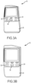
- Figs. 3A-3L illustrate various views of one exemplary embodiment of the pulse generator
- Fig. 4 which is a block diagram depicting one embodiment of the pulse generator 15
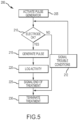
- Fig. 5 which is a flow chart illustrating one embodiment of a method for operation of the pulse generator 15.
- the sealed body 25 protects the internal components and prevents liquids, etc. from penetrating the body and damaging internal components.
- the pulse generator 15 is housed in a rectangular hard plastic case 25 with dimensions of approximately 115mm (4.5in) H x 69mm (2.7in) W x 27mm (1.1in) D and a weight of 145gr (5.1oz) without a battery.
- the body or case may be made of a metallic alloy or a composite material.
- the body 25 includes a front portion 26 and a back portion 27. The front and back portion are sealingly engaged to prevent fluids, etc. from entering the body and interfering with the internal and electrical components housed within the body.
- the body 25 may include raised features 28 configured to provide a gripping surface by which a user, physician, etc. can open the pulse generator to, for example, replace a battery or other electrical component.
- the pulse generator 15 may also include user control features 30, e.g. buttons, that allow the user to turn the power on and off or that provide a temporary lock.
- the user control features 30 may be up and down arrow buttons that allow the patient-user to adjust the stimulus amplitude. In some embodiments, this is the only parameter which is user-adjustable (all others are controlled via the physician's programming).
- the pulse generator 15 may also include a power inlet port 36.
- the power inlet port 36 is configured to accept a connector from a power supply source, such as a DC power supply.
- a power supply source such as a DC power supply.
- the pulse generator is powered by a battery and/or the power supply source (not shown).
- the pulse generator 15 also includes a display 40, such as an LED or LCD screen, to display a graphical user interface (GUI).
- the display may also be controlled by a microcontroller 126 on a display PCB 128.
- the display PCB 128 is coupled to the pulse generator microcontroller 125 on the microcontroller PCB 129 via a ribbon 127.
- the display 40 may be manipulated by user control features 30 that allow the physician and patient to select specific graphical menus.
- the user control features 30 may be generated on the GUI or may be features of or integrated with the case 25.
- the GUI may include a touch-screen interface, thereby allowing the user-patient to make a selection by touching it on the screen.
- the pulse generator is coupled to a power source 100.
- the pulse generator 15 is operably coupled to a battery 100.
- the power source may be any suitable power source, such as a fuel cell, or etc.
- the battery 100 is rechargeable using inductive coupling to the patient's home base station. In some embodiments, the rechargeable battery has a 5 year life.
- the battery 100 and/or the pulse generator 25 may be operably coupled to a (an additional) power supply or charging station 115, such as the patient's home base station.
- the battery may be an internal lithium rechargeable battery.
- the battery has a capacity up to 1000 mA-hours to last a minimum of 36-48 hours between charges.
- the pulse generator may also be used in conjunction with the patient recharging station.
- the patient recharging station is a bedside stand and recharging facility for storing the device when not in use.
- the pulse generator 15 is also operably coupled to electrodes 105 (which may be a part of the electrode assembly 10).
- the pulse generator 15 may be coupled to the electrodes 105 via the wire 20 or the generator 15 and the electrodes 105 may be wirelessly coupled.
- the electrodes 105 and the generator 15 may be a single unit, e.g.
- thegenerator 15 is connected directly to and positioned generally on the electrode.
- the electrode 105 may be replaced daily (or at another appropriate time) but the generator 15 is reusable. In other embodiments, the generator may be intended for a single-time use (non-reusable).
- the electrodes 105 may provide data to the pulse generator 15 and the generator 15 may, in turn, produce an output 120, such as notification to the patient that an electrode has become disconnected or that an electrode needs to be repositioned.
- the pulse generator 15 may further include a digital display of some or all parameters including output current and skin impedance. As indicated in Fig. 4 , the pulse generator 15 is in communication with a storage medium 110. In some embodiments, the storage medium is integrated with the pulse generator.
- the storage medium is a separate component of the system.
- the pulse generator 15 includes a microcontroller 125, or other suitable processor, for receiving and executing instructions from a storage medium 110, such as a non-volatile storage medium, magnetic storage medium, optical storage medium, flash memory, other computer readable medium, or suitable memory device.
- a processor such as the microcontroller 125, may control operation of the pulse generator 15.
- the processor 125 may be any electronic device cable of processing, receiving and/or transmitting instructions.
- the processor 125 may be a microprocessor, a microcomputer and the like.
- Various features to be implemented by the programmable microcontroller 125 of the pulse generator 15 are discussed in more detail with reference to Fig. 5 .
- Fig. 5 is a flow chart illustrating one embodiment of a method 200 for operating a pulse generator in accordance with the present disclosure.
- the method 200 may be performed by the microcontroller 125, or other suitable processor executing instructions from a computer readable medium. It should be appreciated that the operations of the method 200 may be performed in the order illustrated, in another suitable order and/or one or more operations may be performed simultaneously. Moreover, in some embodiments, the method 200 may include more orfewer operations than those illustrated.
- a biometric identification system e.g. a thumbprint
- the PIN or biometric ID prevent sharing of devices and may reduce the risk of clinically inappropriate use by other individuals.
- the method may proceed to operation 215-pulse generation.
- the method proceeds to operation 212. For example, if impedance suddenly becomes high, then a signal will be sent to indicate that the electrodes have become disconnected ("infinite" impedance). If impedance is low or excessively low, then the user is prompted to relocate the electrodes (e.g. there is a need to reposition the electrode to ensure skin safety). In some embodiments, the signal may also be sent or alternatively sent to a physician or other care provider and/or a designated family member. The pulse generator may signal such trouble conditions. Treatment may be terminated or the patient may adjust the electrodes as indicated and restart treatment (e.g. turning the pulse generator off and then back on or the pulse generator may perform another electrode check).
- the programmable microcontroller 125 limits output current. That is, the patient-adjustable current is limited to approximately less than 35 mA to maximize tolerance, minimize current and charge density, and minimize any potential for current penetration through the skull.
- the controller 125 may deliver true square-wave charge-balanced output. This may be advantageous because existing commercial TENS units have asymmetric output, resulting in irregular stimulation, and risk for formation of hotspots, which may contribute to skin irritation or injury. In some embodiments, asymmetric waveforms may be employed, provided the specific signals are safe.
- the microcontroller may be set to a range of outputs. In one embodiment, the range may be set to approximately between 2.5mA and approximately 7mA. In one embodiment, the microcontroller limits the output current to approximately 7 mA, and the patient may adjust the current within a range below 7mA. In another embodiment, the microcontroller can limit the output current to a narrow range (e.g. to ensure safety and compliance) of between approximately 2.5 mA to approximately 5 mA using an external electrode two or four contact electrode. In this way, the patient is prevented from delivering current at too high or too low of an output. In still another embodiment, the output current may be limited to an exact current, e.g.
- the method 200 may further include an operation 220 in which the activity of the pulse generator is logged.
- the logging of use operation 220 may include: (1) recording data for each session, such as: (a) session start date-and-time; (b) session stop date-and-time (actual time treatment was ended), (c) user-adjustable setting (e.g. actual current delivered), and (d) session-specific data (e.g. max & min impedance, electrode & configuration).
- the operation 220 may also include: logging operational anomalies (e.g. electrode disconnects, low impedances, lock-outs for attempts at unauthorized use, etc.), transferring data to the physician's programming console and may include the capacity to store 6 months of treatment data.
- less than 6 months or greater than 6 months of data may be stored.
- a patient's compliance (adherence) and usage is monitored via, e.g., logfiles. Such monitoring may be used to help monitor use patterns in assessing a patient's response to treatment (e.g., a poor clinical response may be linked to using the device less often than prescribed).
- the pulse generator may also signal operational parameters to the patient. This may be part of the logging of use operation 220 or may be part of a differentor a separate operation. For example, a signal may be sent if the user is locked out for PIN guessing, a signal may indicate the minutes until the generator is unlocked. In another example, a signal may be sent if the need for physician follow-up reprogramming is coming up and the signal indicates how many more days of treatment remain before a "refill" date is reached.
- the pulse generator may also display current time and date in the time zone where programmed, display time left in current session (hr:min) and/or display time needed in charger (hr:min) to be ready for the next session.
- the method 200 may further include an operation 225 in which the end of the authorized treatment period is signaled.
- the operation 230 notifies the user that the treatment period is nearing its end and that a follow up visit with the prescribing doctor for clinical assessment and reprogramming needs to be scheduled.
- notification is made at the start of the session.
- the patient is notified that one less week remains to schedule the visit.
- a daily count-down of days remaining is provided.
- the user is notified that this is the last treatment.
- the treatment is terminated.
- Use of the generator may be suspended (e.g. user is locked out) until reprogrammed by a physician or physician programming console or use of the generator may be terminated.
- Figs. 6 through 26 are directed to another embodiment of the disclosed pulse generator.
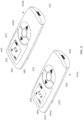
- Fig. 6 is a front perspective view of two of the disclosed pulse generators 610a, 610b.
- the pulse generators 610a, 610b are exact duplicate units, and that the "a" and “b" in the reference numerals in these figures are simply used to indicate the specific pulse generator of the two pulse generators 610a, 610b shown in the figures.
- the pulse generators 610a, 610b may each additionally comprise at least some of the features and/or functionality of the pulse generator 15 of Figs. 2A to 4 .
- the pulse generators 610a, 610b are shown to each include a display 625.
- the display 625 may be a liquid crystal display (LCD) or an organic light-emitting diode (OLED) display.
- the pulse generators 610a, 610b are shown to each include a housing 615, which may be a hard-shell housing (e.g., manufactured from plastic).
- buttons 630, 635, 640 are shown to each include a plurality of buttons 630, 635, 640.
- button 630 is an up-arrow button
- button 640 is a down-arrow button
- button 635 is a lock and set key button.
- buttons 630, 640 are depressed by a user (e.g., a patient, a care giver (such as a parent), and/or a health care professional (such as a physician)) to scroll up and down, respectively, through text, letters, numbers, characters, icons, and/or screens displayed on the display 625 of the pulse generators 610a, 610b.
- the high impedance signal icon 660 when displayed on the display 625, indicates that the system is exhibiting a high impedance (e.g., an impedance greater than a maximum impedance threshold). Refer to the discussion of Figure 25 for details regarding the determination of a high impedance of the system.
- the battery capacity icon 645a shows the amount of battery charge remaining in the battery of the pulse generator 610a. In particular, in Fig. 6 the battery capacity icon 645a is showing that the battery has approximately fifty (50) percent (%) of charge remaining. In one or more embodiments, the pulse generator 610a is able to measure the remaining battery capacity to an accuracy of plus or minus (+/-) five (5) %.
- the pulse generator 610a will switch to a Low Power Mode (e.g., conserving battery capacity) when the battery capacity falls below a predetermined low battery capacity threshold value (e.g., 10 % battery capacity), and/or when an error (e.g., a high impedance) is detected.
- a Low Power Mode e.g., conserving battery capacity
- a predetermined low battery capacity threshold value e.g. 10 % battery capacity
- an error e.g., a high impedance
- a password (or a personal identification number (PIN)) for the patient being entered into the pulse generator 610 by the user (e.g., the patient, a care giver, or a health care professional).
- the password (or PIN) for the patient comprises four numbers, beginning with "820".
- the password (or PIN) for the patient may be generated (e.g., by using a random number generator) by the pulse generator 610a for the patient, or may be programmable (e.g., chosen by and customizable) by the user (e.g., the patient, a care giver, or a health care professional) for the patient.
- the password for the patient may comprise (and may be customizable by the user to comprise) more or less than four digits, as is shown in Fig. 6 .
- the password for the patient may be programmable to comprise only numbers, only letters (which may be case sensitive), only characters, only icons, or a combination of numbers, letters, characters, and/or icons.
- the pulse generator 610a will automatically lock the buttons of the device after a specific duration of time (e.g., 5 minutes) of user inactivity has lapsed.
- the display of pulse generator 610b is shown to display a therapy session screen, which is used by a user (e.g., a patient, a care giver, and/or a health care professional) to program the parameters for a therapy session for the patient.
- a user e.g., a patient, a care giver, and/or a health care professional
- icons include a locked icon 655, a solid connection symbol icon 665, and a battery capacity icon 645b.
- the locked icon 655 when displayed on the display 625, indicates that the buttons 630, 635, 640 are unlocked and are active for use by the user.
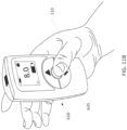
- the user 1110 may use (i.e. depress) the up-arrow button 630 (refer to Fig. 6 ), the down-arrow button 640 (refer to Fig. 6 ), and/or lock and set key the button 635 to enter the patient's password (or PIN) (refer to 670 of Fig. 6 ) into the pulse generator 610 to log into the pulse generator for the patient.
- the user 1110 can input the duration for the therapy session for the patient.
- the user may use (i.e. depress) the up-arrow button 630 (refer to Fig. 6 ), the down-arrow button 640 (refer to Fig. 6 ), and/or the lock and set key button 635 to specify the duration for the therapy session.
- the user 1110 may use (i.e. depress) the up-arrow button 630 (refer to Fig. 6 ), the down-arrow button 640 (refer to Fig. 6 ), and/or the lock and set key button 635 to select a comfortable current amplitude level for the pulses for the patient. For example, the user 1110 may select a comfortable current amplitude level of 5.2 mA at the beginning of the therapy session.
- all of the data collected and logged by the pulse generator 610 during the duration of the therapy session will be stored within the pulse generator 610.
- a user e.g., the patient or a health care provider
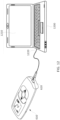
- the computing device 1200 may deliver power to the pulse generator 610 via the cable 1230 to charge the battery of the pulse generator 610.
- the battery shall charge from twenty-five (25) % capacity to full charge within a period of four (4) hours.
- the pulse generator 610 may comprise a light emitting diode (LED) (not shown) to indicate to the user that battery charging is occurring.
- LED light emitting diode
- the user may run an application (e.g., a data downloading application) (e.g., a personal computer (PC) application) on the computing device 1200 to download logged data for a patient from the pulse generator 610 to the computing device 1200.
- an application e.g., a data downloading application
- PC personal computer
- the therapy session parameters (e.g., frequency, pulse width, hold time, rest time, and/or ramp time) for the pulse generator 610 may be programmed by a health care provider using the computing device 1200 (e.g., by means of an application running on the computing device 1200).
- the pulse generator 610 comprises security means (e.g., password protection, password lock out, firewalls, and/or data encryption) for preventing cybersecurity attacks from other devices.
- security means e.g., password protection, password lock out, firewalls, and/or data encryption
- the pulse generator 610 utilizes data encryption to protect patient privacy and data.
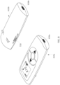
- Fig. 13 is a top plan view of a pulse generator 610 of Fig. 6 .
- the top side of the pulse generator 610 is shown to comprise a receptacle 710.
- Fig. 14 is a bottom plan view of a pulse generator 610 of Fig. 6 .
- the bottom side of the pulse generator 610 is shown to comprise a port 620.
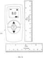
- Fig. 15 is a front plan view of a pulse generator 610 of Fig. 6 next to rulers.
- the pulse generator 610 is shown to have an approximate height of 3.5 inches, and an approximate width of 1.5 inches. It should be noted that in other embodiments, the pulse generator 610 may be manufactured to be of various different height and/or width dimensions than as shown in Fig. 15 .
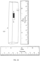
- Fig. 16 is a left side view of a pulse generator 610 of Fig. 6 next to rulers.
- the pulse generator 610 is shown to have an approximate depth of 0.75 inches. It should be noted that in other embodiments, the pulse generator 610 may be manufactured to be of various different depths than as shown in Fig. 16 .
- Figs. 17 - 24 show a plurality of exemplary screens that may be displayed on the display 625 of the pulse generator 610 of Fig. 6 to be used by a heath care provider to obtain logged therapy data for a patient. It should be noted that the screens shown in Figs. 17 - 24 are merely example screens that may be employed by the disclosed system, and that the disclosed system may employ various different versions of these exemplary screens and/or may employ more or less screens than as disclosed herein.
- the screens of Figs.17 - 24 may be displayed on the display 1210 (e.g., refer to Fig. 12 ) of a computing device 1200 (e.g., refer to Fig. 12 ) to be used by a health care provider to obtain (download) logged therapy data for a patient.
- the heath care provider may download the screens of the Figs.17 - 24 via a portable document format (PDF) file.
- PDF portable document format
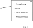
- Fig. 17 is a graphical user interface (GUI) screen 1700 to access a therapy data log for a patient, where the "Average Therapy Data" selection is selected.
- GUI graphical user interface
- screen 1700 displays two selections for the user to select.
- the "Average Therapy Data” selection is shown to have been selected by the user.
- the display 625 will display screen 1800 (refer to Fig. 18 ).
- Fig. 18 is a GUI screen 1800 showing exemplary average therapy data for a patient.
- screen 1800 shows the average therapy data for a patient.
- the average therapy data includes the average therapy amplitude, the average therapy impedance, and the average therapy duration.
- the average therapy data is the average of the data logged for all of the previous therapy sessions for a patient.
- a user may specify which of all of the pervious therapy sessions for the patient that the average therapy data may be calculated (i.e. data from only a select number of therapy sessions for the patient will be used for the calculation of the average therapy data).
- the screen 1800 comprises a "Back" button, which when selected, will cause the display 625 to display the previous screen (e.g., the Therapy Data Log screen). After the user selects the "Back” button the display will display screen 1900 (refer to Fig. 19 ).
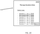
- Fig. 20 is a GUI screen 2000 showing an exemplary historical listing of therapy sessions for a patient, where Therapy Session 2: Jan 2, 2020, is selected.
- screen 2000 shows a listing of all of the past therapy sessions for the patient.
- the "Session 2: Jan 2, 2020" selection is shown to have been selected by the user.
- the display 625 will display screen 2100 (refer to Fig. 21 ).
- Fig. 21 is a GUI screen 2100 showing exemplary therapy data for Therapy Session 2, on January 2, 2020, for a patient, where the "Therapy Amplitudes" selection is selected.
- screen 2100 shows the therapy session duration, the therapy session start time, the therapy session stop time, the average therapy amplitude, and the average therapy impedance.
- the screen 2100 shows two selections for the user to select.
- the screen 2100 shows that the user has selected the "Therapy Amplitudes" selection.
- the display 625 will display screen 2200 (refer to Fig. 22 ).
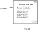
- Fig. 22 is a GUI screen 2200 showing exemplary historical listing of the therapy amplitudes during Therapy Session 2, on January 2, 2020, for a patient.
- screen 2200 shows a listing of all of the therapy amplitudes (which include time stamps) for the patient for this particular therapy session.
- the screen 2200 comprises a "Back" button, which when selected, will cause the display 625 to display the previous screen (e.g., the Session 2: Jan 2, 2020 screen). After the user selects the "Back” button the display will display screen 2300 (refer to Fig. 23 ).
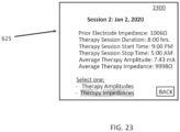
- Fig. 23 is a GUI screen 2300 showing exemplary therapy data for Therapy Session 2, on January 2, 2020, for a patient, where the "Therapy Impedances" selection is selected.
- the screen 2300 shows two selections for the user to select.
- the screen 2100 shows that the user has selected the "Therapy Impedances" selection.
- the display 625 will display screen 2400 (refer to Fig. 24 ).
- Fig. 24 is a GUI screen 2400 showing exemplary historical listing of the therapy impedances during Therapy Session 2, on January 2, 2020, for a patient.
- screen 2300 shows a listing of all of the therapy impedances (which include time stamps) for the patient for this particular therapy session.
- Fig. 25 is a flow chart showing the method for determining whether the impedance of the system (which comprises the pulse generator connected to the electrode assembly) is out of range.
- at least one processor e.g., microprocessor 125
- the pulse generator 610 measures the impedance of the system, which comprises the pulse generator connected to the electrode assembly 2510. Then, at least one processor (e.g., microprocessor 125) of the pulse generator 610 determines whether the measured impedance is less than a base threshold value (e.g., 200 ⁇ ), which would indicate a likely short circuit 2520.
- a base threshold value e.g. 200 ⁇
- the pulse generator 610 determines that the impedance is less than the base threshold value, the pulse generator will discontinue therapy and/or will alert (e.g., by a visual (textual (e.g., ERR) or icon alert and/or an audible alert) the patient that the impedance is below the base threshold value 2530.
- a visual textual (e.g., ERR) or icon alert and/or an audible alert
- At least one processor of the pulse generator 610 determines that the impedance is not less than the base threshold value, at least one processor of the pulse generator 610 will then determine whether the measured impedance is greater than a maximum threshold value (e.g., 15,000 ⁇ ), which would indicate a likely open circuit 2540. If at least one processor of the pulse generator 610 determines that the impedance is greater than the maximum threshold value, the pulse generator will discontinue therapy and/or will alert (e.g., by a visual (textual or icon (e.g., the high impedance signal icon 660 (refer to FIG. 6 )) alert and/or an audible alert) the patient that the impedance is above the maximum threshold value 2550.
- a visual textual or icon
- the method proceeds back to step 2510. Then, the method will continue for the duration of the therapy.
- the pulse generator 610 will switch to the Low Power Mode (e.g., conserving battery capacity) any time an error (e.g., the impedance is below a base threshold or the impedance is above a maximum threshold) is detected.
- the Low Power Mode e.g., conserving battery capacity
- Fig. 26 is a flow chart showing the method for determining whether the battery capacity of a pulse generator 610 of Fig. 6 is sufficient to complete a therapy session for a designated duration.
- at least one processor e.g., microprocessor 125
- the pulse generator 610 determines (reads) the current battery capacity (e.g., 80 % capacity) 2610.
- At least one processor of the pulse generator 610 determines (reads) the duration for the therapy session (e.g., 8.0 hours) 2620.
- the duration for the therapy session e.g., 8.0 hours
- at least one processor of the pulse generator 610 determines (by reviewing logged data for the patient) the average current amplitude of past therapy sessions for the patient 2630.
- At least one processor of the pulse generator 610 determines (by reviewing logged data for the patient) the average therapy impedance of past therapy sessions for the patient 2640.
- At least one processor of the pulse generator 610 determines whether the battery capacity (e.g., 80 % capacity) is sufficient to complete a therapy session for the designation duration (e.g., 8.0 hours) for the patient by using the average current amplitude and the average therapy impedance 2660.
- the battery capacity e.g. 80 % capacity
- At least one processor of the pulse generator 610 determines whether the battery capacity is sufficient for the duration of the therapy session 2670. If at least one processor of the pulse generator 610 determines that the battery capacity is not sufficient for the duration of the therapy session, at least one processor of the pulse generator 610 will alert (e.g., by a visual (textual or icon) alert and/or an audible alert) the patient that the battery capacity is insufficient to complete the therapy session for the duration 2680. In one or more embodiments, Then, if at least one processor of the pulse generator 610 determines that the battery capacity is not sufficient for the duration of the therapy session, at least one processor of the pulse generator 610 will prevent the user from initiating a therapy session at that time. Then, the method ends 2690.
- the electrode assembly 10, 1060 is positioned over the forehead of the patient 5.
- the electrode assembly 10, 1060 may include an insulative connection region which helps to line up the assembly 10, 1060 with the midline of the nose of the patient 5.
- the electrode assembly 10, 1060 is placed over the supraorbital foramina, located over the orbital ridge approximately 2.1-2.6 cm lateral to nasal midline.
- the electrode assembly 10, 1060 is then connected to a pulse generator 15, 610 via the electrical cable 20, 1010.
- the electrode assembly 10, 1060 is connected to the pulse generator 15, 610 via a wireless connection.
- the electrode assembly may be a subcutaneous or percutaneous implantable electrode assembly.
- the electrodes are inserted through the skin but the pulse generator 15, 610 remains external; there may be a lead wire which exits through the skin, or the electrode may be entirely within the skin tissue and they are coupled to a non-implanted pulse generator 15, 610 through, e.g., inductive coupling.
- the pulse generator 15, 610 then provides stimulation according to methods as described herein.
- the pulse generator 15, 610 disclosed herein may be used to treat a disorder or condition in a patient using trigeminal nerve stimulation (TNS).
- TMS trigeminal nerve stimulation
- the method of treatment includes positioning external electrodes over or near at least one of the foramina or branches of the trigeminal nerve ( FIG. 1A-1B ), and stimulating the electrodes using a stimulator or pulse generator 15, 610 as disclosed herein for a fixed time at specified operational parameters.
- the external electrodes are positioned over the foramina of the supraorbital or ophthalmic nerves ( FIG. 1A , Foramen 1).
- the electrode assembly 10, 1060 can be positioned over the foramina of the maxillary nerves ( FIG.
- the stimulation can be unilaterally applied to one foramen of the trigeminal nerves.
- electrodes may be positioned at a region of the patient's face (on the right and/or left side) corresponding with the supratrochlear nerve, infratrochlear nerve, zygomaticotemporal, zygomaticofacial, zygomaticoorbital, mentalis, nasal and/or auriculotemporal nerves and/or their respective foramina.
- subcutaneous implantable electrodes may be used with the pulse generator 15, 610 as disclosed herein. At least one processor (e.g., programmable microcontroller 125 of Fig. 4 ) of the pulse generator 15, 610 may be programmed to operate at one or more of the following parameters.
- the stimulation is delivered at a specific pulse width or range of pulse widths (or pulse duration).
- the stimulation can be set to deliver pulse widths in the range greater than and/or less than one or more of 50 ⁇ s, 60 ⁇ s, 70 ⁇ s, 80 ⁇ s, 90 ⁇ s, 100 ⁇ s, 125 ⁇ s, 150 ⁇ s, 175 ⁇ s, 200 ⁇ s, 225 ⁇ s, 250 ⁇ s, up to 500 ⁇ s.
- Those of skill in the art will recognized that one or more of the above times can be used as a border of a range of pulse widths.
- the stimulation amplitude is delivered as a voltage or current controlled stimulation. In other embodiments it can be delivered as a capacitive discharge.
- the current amplitude can be in any range within a lower limit of about 300 ⁇ A and an upper limit of about 30 mA - 35 mA, depending on the surface area of the electrodes, inter-electrode distance, the branch(es) stimulated, and the modeling data as described above.
- the amplitude can be in a range greater than and/or less than one or more of 50 microamps ( ⁇ A), 75 ⁇ A, 100 ⁇ A, 125 ⁇ A, 150 ⁇ A, 175 ⁇ A, 200 ⁇ A, 225 ⁇ A, 250 ⁇ A, 275 ⁇ A, 300 ⁇ A, 325 ⁇ A, 350 ⁇ A, 375 ⁇ A, 400 ⁇ A, 425 ⁇ A, 450 ⁇ A, 475 ⁇ A, 500 ⁇ A, 525 ⁇ A, 550 ⁇ A, 575 ⁇ A, 600 ⁇ A, 625 ⁇ A, 650 ⁇ A, 675 ⁇ A, 700 ⁇ A, 725 ⁇ A, 850 ⁇ A, 875 ⁇ A, 900 ⁇ A, 925 ⁇ A, 950 ⁇ A, 975 ⁇ A, 1 mA, 2 mA, 3 mA, 4 mA, 5 mA, 6 mA, 7 mA,
- the current amplitudes are less than 7 mA, or less than 6 mA, depending on the size, impedance, resistance, or configuration of the electrode(s). In some embodiments, the current amplitude is between about 2.5mA and about 5 mA. Those of skill in the art will recognize that one or more of the above amplitudes can be used as a border of a range of amplitudes.
- the stimulation can be delivered at one or more frequencies, or within a range of frequencies.
- the stimulation can be set to be delivered at frequencies less than, and/or greater than one or more of 50 Hz, 45 Hz, 40 Hz, 35 Hz, 30 Hz, 25 Hz, 20 Hz, 15 Hz, or 10 Hz.
- the stimulation can be set to be delivered at frequencies greater than, and/or less than, one or more of 20Hz, 30Hz, 40Hz, 50 Hz, 60 Hz, 70 Hz, 80 Hz, 90 Hz, 100 Hz, 120Hz, 125 Hz, 150 Hz, up to 300 Hz.
- Those of skill in the art will recognize that one or more of the above frequencies can be used as a border of a range of frequencies.
Landscapes
- Health & Medical Sciences (AREA)
- Life Sciences & Earth Sciences (AREA)
- General Health & Medical Sciences (AREA)
- Public Health (AREA)
- Engineering & Computer Science (AREA)
- Nuclear Medicine, Radiotherapy & Molecular Imaging (AREA)
- Radiology & Medical Imaging (AREA)
- Animal Behavior & Ethology (AREA)
- Biomedical Technology (AREA)
- Veterinary Medicine (AREA)
- Biophysics (AREA)
- Heart & Thoracic Surgery (AREA)
- Neurology (AREA)
- Psychology (AREA)
- Child & Adolescent Psychology (AREA)
- Hospice & Palliative Care (AREA)
- Psychiatry (AREA)
- Developmental Disabilities (AREA)
- Social Psychology (AREA)
- Physiology (AREA)
- Physical Education & Sports Medicine (AREA)
- Epidemiology (AREA)
- Medical Informatics (AREA)
- Primary Health Care (AREA)
- Electrotherapy Devices (AREA)
- Cardiology (AREA)
- Neurosurgery (AREA)
Claims (9)
- Impulsgeneratorvorrichtung für die Stimulation des Trigeminusnervs, wobei die Impulsgeneratorvorrichtung umfasst:
mindestens einen Prozessor, der für Folgendes konfiguriert ist:Erzeugen von Impulsen, die an eine kutane Elektrodenanordnung für mindestens eine Therapiesitzung für einen Patienten abgegeben werden, wobei die Impulse definierte Eigenschaften haben,Protokollieren von Daten von der mindestens einen Therapiesitzung für den Patienten, wobei die Daten die Impedanz der mit dem Impulsgenerator verbundenen kutanen Elektrodenanordnung während der mindestens einen Therapiesitzung und die Stromamplitude der während der mindestens einen Therapiesitzung erzeugten Impulse umfassen,Bestimmen einer durchschnittlichen Stromamplitude unter Verwendung der Daten, die die Stromamplitude für mindestens eine der mindestens einen Therapiesitzung umfassen,Bestimmen einer durchschnittlichen Therapieimpedanz unter Verwendung der Daten, die die Impedanz für mindestens eine der mindestens einen Therapiesitzung umfassen,Bestimmen einer Ladekapazität einer Batterie des Impulsgenerators vor dem Beginn einer nachfolgenden Therapiesitzung für den Patienten, undBestimmen, ob die Ladekapazität der Batterie des Impulsgenerators ausreicht, um die nachfolgende Therapiesitzung für den Patienten für eine bestimmte Zeitdauer abzuschließen, unter Verwendung der durchschnittlichen Stromamplitude und der durchschnittlichen Therapieimpedanz; undeine Anzeige, die dafür konfiguriert ist, einen Bildschirm anzuzeigen, der eine grafische Benutzeroberfläche (Graphical User Interface, GUI) umfasst. - System nach Anspruch 1, wobei der mindestens eine Prozessor ferner dafür konfiguriert ist, eine Warnung für den Patienten zu erzeugen, die anzeigt, dass die Ladekapazität der Batterie des Impulsgenerators nicht ausreicht, um die nachfolgende Therapiesitzung für die festgelegte Zeitdauer abzuschließen, wenn der mindestens eine Prozessor bestimmt, dass die Ladekapazität der Batterie nicht ausreicht, um die nachfolgende Therapiesitzung für den Patienten für die vorgesehene Zeitdauer abzuschließen.
- System nach Anspruch 2, wobei die Warnung mindestens eine optische oder akustische Warnung ist.
- System nach Anspruch 3, wobei die Anzeige eine Flüssigkristallanzeige (Liquid Crystal Display, LCD) oder eine organische Leuchtdiodenanzeige (OLED) ist.
- System nach Anspruch 1, wobei die Impulsgeneratorvorrichtung mindestens eine Taste umfasst, die zum Programmieren der bestimmten Zeitdauer konfiguriert ist.
- System nach Anspruch 1, wobei der Impulsgenerator solche Abmessungen umfasst, dass der Impulsgenerator in die Hand eines Benutzers passt.
- System nach Anspruch 1, wobei die Stromamplitude der erzeugten Impulse eine Obergrenze von 8,0 mA hat.
- System nach Anspruch 1, wobei der mindestens eine Prozessor ferner dafür konfiguriert ist, die Verwendung des Impulsgenerators einzuschränken, indem er ein Passwort für den Patienten verlangt.
- System nach Anspruch 8, wobei das Passwort für den Patienten programmierbar ist.
Applications Claiming Priority (2)
| Application Number | Priority Date | Filing Date | Title |
|---|---|---|---|
| US202063053288P | 2020-07-17 | 2020-07-17 | |
| PCT/US2021/042029 WO2022016086A1 (en) | 2020-07-17 | 2021-07-16 | Pulse generator for trigeminal nerve stimulation |
Publications (3)
| Publication Number | Publication Date |
|---|---|
| EP4182005A1 EP4182005A1 (de) | 2023-05-24 |
| EP4182005A4 EP4182005A4 (de) | 2024-07-24 |
| EP4182005B1 true EP4182005B1 (de) | 2025-07-02 |
Family
ID=79326919
Family Applications (1)
| Application Number | Title | Priority Date | Filing Date |
|---|---|---|---|
| EP21843569.1A Active EP4182005B1 (de) | 2020-07-17 | 2021-07-16 | Impulsgenerator zur trigeminalen nervenstimulation |
Country Status (7)
| Country | Link |
|---|---|
| US (1) | US20230270995A1 (de) |
| EP (1) | EP4182005B1 (de) |
| JP (1) | JP2023539413A (de) |
| KR (1) | KR20230038780A (de) |
| CN (1) | CN113941088B (de) |
| CA (1) | CA3186187A1 (de) |
| WO (1) | WO2022016086A1 (de) |
Families Citing this family (15)
| Publication number | Priority date | Publication date | Assignee | Title |
|---|---|---|---|---|
| US11266850B2 (en) | 2015-07-01 | 2022-03-08 | Btl Healthcare Technologies A.S. | High power time varying magnetic field therapy |
| US10695575B1 (en) | 2016-05-10 | 2020-06-30 | Btl Medical Technologies S.R.O. | Aesthetic method of biological structure treatment by magnetic field |
| US20180001107A1 (en) | 2016-07-01 | 2018-01-04 | Btl Holdings Limited | Aesthetic method of biological structure treatment by magnetic field |
| US11464993B2 (en) | 2016-05-03 | 2022-10-11 | Btl Healthcare Technologies A.S. | Device including RF source of energy and vacuum system |
| US11534619B2 (en) | 2016-05-10 | 2022-12-27 | Btl Medical Solutions A.S. | Aesthetic method of biological structure treatment by magnetic field |
| US12654023B2 (en) | 2016-05-10 | 2026-06-16 | Btl Medical Solutions A.S. | Aesthetic method of biological structure treatment by magnetic field |
| MX2024007972A (es) | 2018-12-07 | 2024-07-10 | Avent Inc | Dispositivo y metodo para modular selectiva y reversiblemente una estructura de sistema nervioso para inhibir dolor. |
| US12558146B2 (en) | 2019-04-11 | 2026-02-24 | Btl Medical Solutions A.S. | Methods and devices for aesthetic treatment of biological structures by radiofrequency and magnetic energy |
| US11878167B2 (en) | 2020-05-04 | 2024-01-23 | Btl Healthcare Technologies A.S. | Device and method for unattended treatment of a patient |
| HRP20250160T1 (hr) | 2020-05-04 | 2025-03-28 | Btl Healthcare Technologies A.S. | Uređaj za liječenje pacijenata bez prisutnosti liječnika |
| US12611545B2 (en) | 2020-05-04 | 2026-04-28 | Btl Healthcare Technologies A.S. | Device and method for unattended treatment of a patient |
| CA3260012A1 (en) | 2021-10-13 | 2023-04-20 | Btl Medical Solutions A.S. | AESTHETIC TREATMENT DEVICES FOR BIOLOGICAL STRUCTURES USING RADIOFREQUENCY AND MAGNETIC ENERGY |
| CN116531659A (zh) * | 2022-01-25 | 2023-08-04 | 纽罗西格玛公司 | 用于三叉神经刺激的脉冲发生器 |
| CN118079179A (zh) * | 2024-01-31 | 2024-05-28 | 深圳中科华意科技有限公司 | 基于脑电信号的昏迷患者的促醒方法、装置、电子设备及存储介质 |
| US20260097226A1 (en) | 2024-10-08 | 2026-04-09 | Btl Medical Solutions A.S. | Devices and methods for application of a magnetic field to the nervous system |
Family Cites Families (22)
| Publication number | Priority date | Publication date | Assignee | Title |
|---|---|---|---|---|
| GB2403609A (en) * | 2003-07-01 | 2005-01-05 | Univ Leicester | Pulse charging an electrochemical device |
| CN101648053B (zh) * | 2009-09-03 | 2012-05-30 | 清华大学 | 双通道植入式神经刺激器 |
| US10204706B2 (en) * | 2009-10-29 | 2019-02-12 | Medtronic, Inc. | User interface for optimizing energy management in a neurostimulation system |
| US9020589B2 (en) * | 2010-04-27 | 2015-04-28 | Medtronic, Inc. | Electrical stimulator with voltage mode emulation using regulated current |
| CN103313671B (zh) * | 2010-10-25 | 2017-06-06 | 美敦力Af卢森堡有限责任公司 | 用于神经调节治疗的估算及反馈的装置、系统及方法 |
| CA2819346C (en) * | 2010-11-30 | 2020-01-21 | Ian A. Cook | Pulse generator for cranial nerve stimulation |
| JP6130789B2 (ja) * | 2010-12-14 | 2017-05-17 | ザ リージェンツ オブ ザ ユニバーシティ オブ カリフォルニア | 医学的障害の治療のためのデバイス |
| EP2736592B1 (de) * | 2011-07-29 | 2018-01-10 | Micron Devices LLC | Fernsteuerung von leistungs- oder polaritätsauswahl für einen nervenstimulator |
| US9173811B2 (en) * | 2011-09-29 | 2015-11-03 | Valencia Technologies Corporation | Implantable electroacupuncture system and method for treating depression and similar mental conditions |
| CN202933390U (zh) * | 2012-07-13 | 2013-05-15 | 北京品驰医疗设备有限公司 | 体外用测试刺激器 |
| NO339651B1 (no) * | 2013-09-11 | 2017-01-16 | Nevroflex AS | Stimulerings- og behandlingsinnretning |
| US10946194B2 (en) * | 2013-11-27 | 2021-03-16 | Ebt Medical, Inc. | System for improving neurostimulation compliance |
| US10688306B2 (en) * | 2013-12-23 | 2020-06-23 | Deep Brain Innovations LLC | Programming systems for deep brain stimulator system |
| JP6543635B2 (ja) * | 2014-01-16 | 2019-07-10 | アイシーユー・メディカル・インコーポレーテッド | 輸液ポンプの電池容量管理および電池充電アラートシステムならびに方法 |
| KR102386264B1 (ko) * | 2014-05-20 | 2022-04-13 | 일렉트로코어, 엘엘씨 | 휴대 장치를 통한 비 침습성 신경 자극 |
| EP3191176B1 (de) * | 2014-10-22 | 2024-04-10 | Nevro Corp. | Systeme und verfahren zur verlängerung der lebensdauer einer implantierten pulserzeugungsbatterie |
| CN107427675B (zh) * | 2015-01-09 | 2021-10-26 | 艾克索尼克斯股份有限公司 | 患者遥控器及其与神经刺激系统一起使用的相关联方法 |
| KR20180040670A (ko) * | 2015-08-13 | 2018-04-20 | 코비디엔 아게 | 전기수술 발전기 및 방법 |
| US10300282B2 (en) * | 2015-09-18 | 2019-05-28 | Medtronic, Inc. | Electrical stimulation therapy for inducing patient sensations |
| JP6907783B2 (ja) * | 2017-07-27 | 2021-07-21 | オムロンヘルスケア株式会社 | 電気治療器、制御方法、および治療システム |
| US11559308B2 (en) * | 2017-12-28 | 2023-01-24 | Cilag Gmbh International | Method for smart energy device infrastructure |
| WO2019195400A1 (en) * | 2018-04-03 | 2019-10-10 | John Rabolt | Method and device for mitigating a health-related condition |
-
2020
- 2020-07-29 CN CN202010741979.3A patent/CN113941088B/zh active Active
-
2021
- 2021-07-16 EP EP21843569.1A patent/EP4182005B1/de active Active
- 2021-07-16 US US18/016,453 patent/US20230270995A1/en active Pending
- 2021-07-16 WO PCT/US2021/042029 patent/WO2022016086A1/en not_active Ceased
- 2021-07-16 CA CA3186187A patent/CA3186187A1/en active Pending
- 2021-07-16 KR KR1020237005563A patent/KR20230038780A/ko active Pending
- 2021-07-16 JP JP2023503133A patent/JP2023539413A/ja active Pending
Also Published As
| Publication number | Publication date |
|---|---|
| EP4182005A1 (de) | 2023-05-24 |
| EP4182005A4 (de) | 2024-07-24 |
| US20230270995A1 (en) | 2023-08-31 |
| CA3186187A1 (en) | 2022-01-20 |
| WO2022016086A1 (en) | 2022-01-20 |
| JP2023539413A (ja) | 2023-09-14 |
| CN113941088B (zh) | 2025-07-29 |
| CN113941088A (zh) | 2022-01-18 |
| KR20230038780A (ko) | 2023-03-21 |
Similar Documents
| Publication | Publication Date | Title |
|---|---|---|
| US20250144416A1 (en) | Pulse generator for trigeminal nerve stimulation | |
| US20230270995A1 (en) | Pulse generator for trigeminal nerve stimulation | |
| US10016601B2 (en) | Pulse generator for cranial nerve stimulation | |
| US12201834B2 (en) | Apparatuses and methods for transdermal electrical stimulation of nerves to modify or induce a cognitive state | |
| US10293161B2 (en) | Apparatuses and methods for transdermal electrical stimulation of nerves to modify or induce a cognitive state | |
| US20170165485A1 (en) | Systems and methods for non-invasive treatment of head pain | |
| US9180303B2 (en) | Transmission of power source usage information over a network | |
| US20170368344A1 (en) | Treatment of headaches by electrical stimulation | |
| AU2014257024B2 (en) | Modulation of autonomic nervous system activity and integrated electrode assemblies for trigeminal neurostimulation | |
| US8706181B2 (en) | Target therapy delivery site selection | |
| US20160144175A1 (en) | Medical self-treatment using non-invasive vagus nerve stimulation | |
| US20150119898A1 (en) | Subcutaneous electrodes for cranial nerve stimulation | |
| CN103313754A (zh) | 用于治疗干眼的系统和方法 | |
| EP4149613B1 (de) | Elektrodensystem zur sichtbehandlung | |
| CN114845768B (zh) | 提供亚感知刺激的神经刺激设备 | |
| CN116322893A (zh) | 脑刺激疗法 | |
| HK40098014A (en) | Pulse generator for trigeminal nerve stimulation | |
| US12589243B2 (en) | Ocular devices and controller interfaces for ocular therapy |
Legal Events
| Date | Code | Title | Description |
|---|---|---|---|
| STAA | Information on the status of an ep patent application or granted ep patent |
Free format text: STATUS: THE INTERNATIONAL PUBLICATION HAS BEEN MADE |
|
| PUAI | Public reference made under article 153(3) epc to a published international application that has entered the european phase |
Free format text: ORIGINAL CODE: 0009012 |
|
| STAA | Information on the status of an ep patent application or granted ep patent |
Free format text: STATUS: REQUEST FOR EXAMINATION WAS MADE |
|
| 17P | Request for examination filed |
Effective date: 20230123 |
|
| AK | Designated contracting states |
Kind code of ref document: A1 Designated state(s): AL AT BE BG CH CY CZ DE DK EE ES FI FR GB GR HR HU IE IS IT LI LT LU LV MC MK MT NL NO PL PT RO RS SE SI SK SM TR |
|
| DAV | Request for validation of the european patent (deleted) | ||
| DAX | Request for extension of the european patent (deleted) | ||
| A4 | Supplementary search report drawn up and despatched |
Effective date: 20240620 |
|
| RIC1 | Information provided on ipc code assigned before grant |
Ipc: A61N 1/32 20060101ALN20240614BHEP Ipc: A61N 1/05 20060101ALN20240614BHEP Ipc: A61N 1/04 20060101ALI20240614BHEP Ipc: A61N 1/36 20060101ALI20240614BHEP Ipc: A61N 1/378 20060101ALI20240614BHEP Ipc: A61N 1/02 20060101AFI20240614BHEP |
|
| GRAP | Despatch of communication of intention to grant a patent |
Free format text: ORIGINAL CODE: EPIDOSNIGR1 |
|
| STAA | Information on the status of an ep patent application or granted ep patent |
Free format text: STATUS: GRANT OF PATENT IS INTENDED |
|
| RIC1 | Information provided on ipc code assigned before grant |
Ipc: A61N 1/32 20060101ALN20250203BHEP Ipc: A61N 1/05 20060101ALN20250203BHEP Ipc: A61N 1/04 20060101ALI20250203BHEP Ipc: A61N 1/36 20060101ALI20250203BHEP Ipc: A61N 1/378 20060101ALI20250203BHEP Ipc: A61N 1/02 20060101AFI20250203BHEP |
|
| INTG | Intention to grant announced |
Effective date: 20250214 |
|
| RIN1 | Information on inventor provided before grant (corrected) |
Inventor name: MILLER, PATRICK |
|
| GRAS | Grant fee paid |
Free format text: ORIGINAL CODE: EPIDOSNIGR3 |
|
| GRAA | (expected) grant |
Free format text: ORIGINAL CODE: 0009210 |
|
| STAA | Information on the status of an ep patent application or granted ep patent |
Free format text: STATUS: THE PATENT HAS BEEN GRANTED |
|
| AK | Designated contracting states |
Kind code of ref document: B1 Designated state(s): AL AT BE BG CH CY CZ DE DK EE ES FI FR GB GR HR HU IE IS IT LI LT LU LV MC MK MT NL NO PL PT RO RS SE SI SK SM TR |
|
| REG | Reference to a national code |
Ref country code: GB Ref legal event code: FG4D |
|
| REG | Reference to a national code |
Ref country code: CH Ref legal event code: EP |
|
| REG | Reference to a national code |
Ref country code: DE Ref legal event code: R096 Ref document number: 602021033529 Country of ref document: DE |
|
| REG | Reference to a national code |
Ref country code: IE Ref legal event code: FG4D |
|
| PGFP | Annual fee paid to national office [announced via postgrant information from national office to epo] |
Ref country code: AT Payment date: 20251020 Year of fee payment: 5 |
|
| REG | Reference to a national code |
Ref country code: NL Ref legal event code: MP Effective date: 20250702 |
|
| PG25 | Lapsed in a contracting state [announced via postgrant information from national office to epo] |
Ref country code: PT Free format text: LAPSE BECAUSE OF FAILURE TO SUBMIT A TRANSLATION OF THE DESCRIPTION OR TO PAY THE FEE WITHIN THE PRESCRIBED TIME-LIMIT Effective date: 20251103 |
|
| PG25 | Lapsed in a contracting state [announced via postgrant information from national office to epo] |
Ref country code: NL Free format text: LAPSE BECAUSE OF FAILURE TO SUBMIT A TRANSLATION OF THE DESCRIPTION OR TO PAY THE FEE WITHIN THE PRESCRIBED TIME-LIMIT Effective date: 20250702 |
|
| REG | Reference to a national code |
Ref country code: AT Ref legal event code: MK05 Ref document number: 1808584 Country of ref document: AT Kind code of ref document: T Effective date: 20250702 |
|
| PG25 | Lapsed in a contracting state [announced via postgrant information from national office to epo] |
Ref country code: IS Free format text: LAPSE BECAUSE OF FAILURE TO SUBMIT A TRANSLATION OF THE DESCRIPTION OR TO PAY THE FEE WITHIN THE PRESCRIBED TIME-LIMIT Effective date: 20251102 |
|
| PGFP | Annual fee paid to national office [announced via postgrant information from national office to epo] |
Ref country code: DE Payment date: 20251029 Year of fee payment: 5 |
|
| PGFP | Annual fee paid to national office [announced via postgrant information from national office to epo] |
Ref country code: GB Payment date: 20251027 Year of fee payment: 5 |
|
| PG25 | Lapsed in a contracting state [announced via postgrant information from national office to epo] |
Ref country code: NO Free format text: LAPSE BECAUSE OF FAILURE TO SUBMIT A TRANSLATION OF THE DESCRIPTION OR TO PAY THE FEE WITHIN THE PRESCRIBED TIME-LIMIT Effective date: 20251002 |
|
| REG | Reference to a national code |
Ref country code: LT Ref legal event code: MG9D |
|
| PG25 | Lapsed in a contracting state [announced via postgrant information from national office to epo] |
Ref country code: AT Free format text: LAPSE BECAUSE OF FAILURE TO SUBMIT A TRANSLATION OF THE DESCRIPTION OR TO PAY THE FEE WITHIN THE PRESCRIBED TIME-LIMIT Effective date: 20250702 |
|
| PG25 | Lapsed in a contracting state [announced via postgrant information from national office to epo] |
Ref country code: FI Free format text: LAPSE BECAUSE OF FAILURE TO SUBMIT A TRANSLATION OF THE DESCRIPTION OR TO PAY THE FEE WITHIN THE PRESCRIBED TIME-LIMIT Effective date: 20250702 |
|
| PG25 | Lapsed in a contracting state [announced via postgrant information from national office to epo] |
Ref country code: HR Free format text: LAPSE BECAUSE OF FAILURE TO SUBMIT A TRANSLATION OF THE DESCRIPTION OR TO PAY THE FEE WITHIN THE PRESCRIBED TIME-LIMIT Effective date: 20250702 |
|
| PGFP | Annual fee paid to national office [announced via postgrant information from national office to epo] |
Ref country code: FR Payment date: 20251027 Year of fee payment: 5 |
|
| PG25 | Lapsed in a contracting state [announced via postgrant information from national office to epo] |
Ref country code: GR Free format text: LAPSE BECAUSE OF FAILURE TO SUBMIT A TRANSLATION OF THE DESCRIPTION OR TO PAY THE FEE WITHIN THE PRESCRIBED TIME-LIMIT Effective date: 20251003 |
|
| PG25 | Lapsed in a contracting state [announced via postgrant information from national office to epo] |
Ref country code: CZ Free format text: LAPSE BECAUSE OF FAILURE TO SUBMIT A TRANSLATION OF THE DESCRIPTION OR TO PAY THE FEE WITHIN THE PRESCRIBED TIME-LIMIT Effective date: 20250702 Ref country code: SE Free format text: LAPSE BECAUSE OF FAILURE TO SUBMIT A TRANSLATION OF THE DESCRIPTION OR TO PAY THE FEE WITHIN THE PRESCRIBED TIME-LIMIT Effective date: 20250702 |
|
| PG25 | Lapsed in a contracting state [announced via postgrant information from national office to epo] |
Ref country code: LV Free format text: LAPSE BECAUSE OF FAILURE TO SUBMIT A TRANSLATION OF THE DESCRIPTION OR TO PAY THE FEE WITHIN THE PRESCRIBED TIME-LIMIT Effective date: 20250702 |
|
| PG25 | Lapsed in a contracting state [announced via postgrant information from national office to epo] |
Ref country code: BG Free format text: LAPSE BECAUSE OF FAILURE TO SUBMIT A TRANSLATION OF THE DESCRIPTION OR TO PAY THE FEE WITHIN THE PRESCRIBED TIME-LIMIT Effective date: 20250702 Ref country code: PL Free format text: LAPSE BECAUSE OF FAILURE TO SUBMIT A TRANSLATION OF THE DESCRIPTION OR TO PAY THE FEE WITHIN THE PRESCRIBED TIME-LIMIT Effective date: 20250702 |
|
| PG25 | Lapsed in a contracting state [announced via postgrant information from national office to epo] |
Ref country code: RS Free format text: LAPSE BECAUSE OF FAILURE TO SUBMIT A TRANSLATION OF THE DESCRIPTION OR TO PAY THE FEE WITHIN THE PRESCRIBED TIME-LIMIT Effective date: 20251002 |
|
| PG25 | Lapsed in a contracting state [announced via postgrant information from national office to epo] |
Ref country code: ES Free format text: LAPSE BECAUSE OF FAILURE TO SUBMIT A TRANSLATION OF THE DESCRIPTION OR TO PAY THE FEE WITHIN THE PRESCRIBED TIME-LIMIT Effective date: 20250702 |
|
| REG | Reference to a national code |
Ref country code: CH Ref legal event code: H13 Free format text: ST27 STATUS EVENT CODE: U-0-0-H10-H13 (AS PROVIDED BY THE NATIONAL OFFICE) Effective date: 20260224 |
|
| PG25 | Lapsed in a contracting state [announced via postgrant information from national office to epo] |
Ref country code: LU Free format text: LAPSE BECAUSE OF NON-PAYMENT OF DUE FEES Effective date: 20250716 Ref country code: RO Free format text: LAPSE BECAUSE OF FAILURE TO SUBMIT A TRANSLATION OF THE DESCRIPTION OR TO PAY THE FEE WITHIN THE PRESCRIBED TIME-LIMIT Effective date: 20250702 |
|
| REG | Reference to a national code |
Ref country code: BE Ref legal event code: MM Effective date: 20250731 |
|
| PG25 | Lapsed in a contracting state [announced via postgrant information from national office to epo] |
Ref country code: SM Free format text: LAPSE BECAUSE OF FAILURE TO SUBMIT A TRANSLATION OF THE DESCRIPTION OR TO PAY THE FEE WITHIN THE PRESCRIBED TIME-LIMIT Effective date: 20250702 |
|
| REG | Reference to a national code |
Ref country code: DE Ref legal event code: R097 Ref document number: 602021033529 Country of ref document: DE |
|
| PG25 | Lapsed in a contracting state [announced via postgrant information from national office to epo] |
Ref country code: DK Free format text: LAPSE BECAUSE OF FAILURE TO SUBMIT A TRANSLATION OF THE DESCRIPTION OR TO PAY THE FEE WITHIN THE PRESCRIBED TIME-LIMIT Effective date: 20250702 |
|
| PG25 | Lapsed in a contracting state [announced via postgrant information from national office to epo] |
Ref country code: IT Free format text: LAPSE BECAUSE OF FAILURE TO SUBMIT A TRANSLATION OF THE DESCRIPTION OR TO PAY THE FEE WITHIN THE PRESCRIBED TIME-LIMIT Effective date: 20250702 Ref country code: BE Free format text: LAPSE BECAUSE OF NON-PAYMENT OF DUE FEES Effective date: 20250731 |
|
| PG25 | Lapsed in a contracting state [announced via postgrant information from national office to epo] |
Ref country code: CH Free format text: LAPSE BECAUSE OF NON-PAYMENT OF DUE FEES Effective date: 20250731 |
|
| PG25 | Lapsed in a contracting state [announced via postgrant information from national office to epo] |
Ref country code: SK Free format text: LAPSE BECAUSE OF FAILURE TO SUBMIT A TRANSLATION OF THE DESCRIPTION OR TO PAY THE FEE WITHIN THE PRESCRIBED TIME-LIMIT Effective date: 20250702 Ref country code: EE Free format text: LAPSE BECAUSE OF FAILURE TO SUBMIT A TRANSLATION OF THE DESCRIPTION OR TO PAY THE FEE WITHIN THE PRESCRIBED TIME-LIMIT Effective date: 20250702 |
|
| PLBE | No opposition filed within time limit |
Free format text: ORIGINAL CODE: 0009261 |
|
| STAA | Information on the status of an ep patent application or granted ep patent |
Free format text: STATUS: NO OPPOSITION FILED WITHIN TIME LIMIT |
|
| REG | Reference to a national code |
Ref country code: CH Ref legal event code: L10 Free format text: ST27 STATUS EVENT CODE: U-0-0-L10-L00 (AS PROVIDED BY THE NATIONAL OFFICE) Effective date: 20260518 |
|
| 26N | No opposition filed |
Effective date: 20260407 |
|
| PG25 | Lapsed in a contracting state [announced via postgrant information from national office to epo] |
Ref country code: MC Free format text: LAPSE BECAUSE OF FAILURE TO SUBMIT A TRANSLATION OF THE DESCRIPTION OR TO PAY THE FEE WITHIN THE PRESCRIBED TIME-LIMIT Effective date: 20250702 Ref country code: LT Free format text: LAPSE BECAUSE OF FAILURE TO SUBMIT A TRANSLATION OF THE DESCRIPTION OR TO PAY THE FEE WITHIN THE PRESCRIBED TIME-LIMIT Effective date: 20250702 |
|
| PG25 | Lapsed in a contracting state [announced via postgrant information from national office to epo] |
Ref country code: IE Free format text: LAPSE BECAUSE OF NON-PAYMENT OF DUE FEES Effective date: 20250716 |
|
| PG25 | Lapsed in a contracting state [announced via postgrant information from national office to epo] |
Ref country code: CY Free format text: LAPSE BECAUSE OF FAILURE TO SUBMIT A TRANSLATION OF THE DESCRIPTION OR TO PAY THE FEE WITHIN THE PRESCRIBED TIME-LIMIT Effective date: 20250702 |