EP4181696B1 - Dispositif de fabrication d'articles en forme de tige à segments multiples - Google Patents
Dispositif de fabrication d'articles en forme de tige à segments multiples Download PDFInfo
- Publication number
- EP4181696B1 EP4181696B1 EP21742149.4A EP21742149A EP4181696B1 EP 4181696 B1 EP4181696 B1 EP 4181696B1 EP 21742149 A EP21742149 A EP 21742149A EP 4181696 B1 EP4181696 B1 EP 4181696B1
- Authority
- EP
- European Patent Office
- Prior art keywords
- segments
- rotary pressing
- segment
- pressing element
- rotary
- Prior art date
- Legal status (The legal status is an assumption and is not a legal conclusion. Google has not performed a legal analysis and makes no representation as to the accuracy of the status listed.)
- Active
Links
- 238000004519 manufacturing process Methods 0.000 title claims description 15
- 238000003825 pressing Methods 0.000 claims description 78
- 238000005520 cutting process Methods 0.000 claims description 8
- 230000002093 peripheral effect Effects 0.000 claims description 3
- 239000012634 fragment Substances 0.000 description 8
- 239000000463 material Substances 0.000 description 8
- 235000019504 cigarettes Nutrition 0.000 description 5
- 238000001914 filtration Methods 0.000 description 4
- 241000208125 Nicotiana Species 0.000 description 3
- 235000002637 Nicotiana tabacum Nutrition 0.000 description 3
- 239000000853 adhesive Substances 0.000 description 3
- 230000001070 adhesive effect Effects 0.000 description 3
- 239000003292 glue Substances 0.000 description 2
- QTBSBXVTEAMEQO-UHFFFAOYSA-M Acetate Chemical compound CC([O-])=O QTBSBXVTEAMEQO-UHFFFAOYSA-M 0.000 description 1
- 238000004026 adhesive bonding Methods 0.000 description 1
- 230000006835 compression Effects 0.000 description 1
- 238000007906 compression Methods 0.000 description 1
- 230000002950 deficient Effects 0.000 description 1
- 239000000835 fiber Substances 0.000 description 1
- 238000000034 method Methods 0.000 description 1
- 230000003252 repetitive effect Effects 0.000 description 1
- 238000000926 separation method Methods 0.000 description 1
- 239000000779 smoke Substances 0.000 description 1
- 239000000126 substance Substances 0.000 description 1
Images

Classifications
-
- A—HUMAN NECESSITIES
- A24—TOBACCO; CIGARS; CIGARETTES; SIMULATED SMOKING DEVICES; SMOKERS' REQUISITES
- A24D—CIGARS; CIGARETTES; TOBACCO SMOKE FILTERS; MOUTHPIECES FOR CIGARS OR CIGARETTES; MANUFACTURE OF TOBACCO SMOKE FILTERS OR MOUTHPIECES
- A24D3/00—Tobacco smoke filters, e.g. filter-tips, filtering inserts; Filters specially adapted for simulated smoking devices; Mouthpieces for cigars or cigarettes
- A24D3/02—Manufacture of tobacco smoke filters
- A24D3/0275—Manufacture of tobacco smoke filters for filters with special features
-
- A—HUMAN NECESSITIES
- A24—TOBACCO; CIGARS; CIGARETTES; SIMULATED SMOKING DEVICES; SMOKERS' REQUISITES
- A24C—MACHINES FOR MAKING CIGARS OR CIGARETTES
- A24C5/00—Making cigarettes; Making tipping materials for, or attaching filters or mouthpieces to, cigars or cigarettes
- A24C5/01—Making cigarettes for simulated smoking devices
-
- A—HUMAN NECESSITIES
- A24—TOBACCO; CIGARS; CIGARETTES; SIMULATED SMOKING DEVICES; SMOKERS' REQUISITES
- A24D—CIGARS; CIGARETTES; TOBACCO SMOKE FILTERS; MOUTHPIECES FOR CIGARS OR CIGARETTES; MANUFACTURE OF TOBACCO SMOKE FILTERS OR MOUTHPIECES
- A24D3/00—Tobacco smoke filters, e.g. filter-tips, filtering inserts; Filters specially adapted for simulated smoking devices; Mouthpieces for cigars or cigarettes
- A24D3/02—Manufacture of tobacco smoke filters
- A24D3/027—Multiple line manufacturing devices
-
- A—HUMAN NECESSITIES
- A24—TOBACCO; CIGARS; CIGARETTES; SIMULATED SMOKING DEVICES; SMOKERS' REQUISITES
- A24D—CIGARS; CIGARETTES; TOBACCO SMOKE FILTERS; MOUTHPIECES FOR CIGARS OR CIGARETTES; MANUFACTURE OF TOBACCO SMOKE FILTERS OR MOUTHPIECES
- A24D3/00—Tobacco smoke filters, e.g. filter-tips, filtering inserts; Filters specially adapted for simulated smoking devices; Mouthpieces for cigars or cigarettes
- A24D3/02—Manufacture of tobacco smoke filters
- A24D3/0275—Manufacture of tobacco smoke filters for filters with special features
- A24D3/0287—Manufacture of tobacco smoke filters for filters with special features for composite filters
Definitions
- the present disclosure relates to a device for manufacturing multi-segment rod-like articles.
- cigarettes comprising filters are manufactured, wherein the filters may be formed from one type of material or may be formed from various materials having different physical and filtering properties.
- Filtering material in a continuous form for example acetate in a form of fibers, is cut into rods and is applied to cigarettes.
- filters which comprise multiple segments formed from different materials.
- multi-segment filter rods wherein the multi-segment filter rods comprise segments formed from various types of the filtering material, as well as segments having a non-filtering function, which separate the filter segments or form only a through channel for tobacco smoke or for heated air comprising volatile substances.
- the machines arrange the segments formed by cutting rods of various materials.
- the rods are fed from multiple feeding devices, wherein the segments are formed by cutting filter rods, transferred for example on a drum conveyor, by means of a cutting head equipped with disc knives.
- the individual segments are arranged side by side on a drum conveyor or one after another on a linear transporter to finally form a continuous multi-segment rod transferred linearly, which is cut into individual multi-segment rods.
- the multi-segment rods are cut into individual multi-segment mouthpieces which are applied into individual cigarettes.
- the arrangement of segments linearly and longitudinally one after another takes place on a conveyor belt, on which a wrapper tape is transferred.
- a very important factor that determined the quality of the manufactured rods is the coaxial arrangement of the segments on the belt conveyor immediately after the segments are placed on the conveyor. This is particularly important in relation to thin-walled tube segments, because a misaligned positioning of the segments may result in a defective connection that will not be automatically eliminated before being wrapped into the wrapper.
- the currently used feeding units comprise a feeding wheel, which places groups of segments onto the transporter.
- EP2767177 discloses a mechanism for a momentary compression of a filter material used in the tobacco industry, wrapped into a wrapper and glued with an adhesive delivered from an adhesive applying apparatus, adapted to being placed on a machine for manufacturing filter rods before the adhesive applying apparatus, which comprises at least one rotary compressing member for pressing the filter material linearly moving underneath it.
- the aim of the present invention is to provide an improved device, which provides a correct, i.e. axial alignment of the segments on the transporter belt, in particular of the thin-walled segments and long segments.
- this task may also be defined as positioning the neighboring segments such, that the misaligned positioning of the front surfaces of the segments with respect to each other is reduced.
- the invention is related to a device for manufacturing multi-segment rod-like articles according to the appended claims.
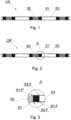
- Fig. 1 shows a continuous multi-segment rod CR manufactured on a device for manufacturing multi-segment rods.
- the continuous multi-segment rod CR is formed from a train of segments S1, S2, S3 in a repetitive sequence, wherein the train of segments is wrapped in a continuous wrapper.
- Fig. 2 shows a continuous multi-segment rod CR', wherein a segment S1 is misaligned with respect to neighboring segments S2 and S3, wherein the segment S3 has a form of a thin-walled tube.
- a front surface S3-F of the segment S3 is dislocated with respect to a front surface S1-F of the segment S1, i.e. the front surface S3-F and the front surface S1-F are positioned non-concentrically, it means that segment 3 and segment 1 are not coaxial with each other.
- a front surface S1-F' of the segment S1 is misaligned with respect to a front surface S2-F of the segment S2, i.e.
- the front surface S1-F' and the front surface S2-F are also positioned non-concentrically, it means that segment 3 and segment 2 are arranged not coaxially. Due to the fact that the segment S3 has a form of a thin-walled tube, the edge of the segment S1 may enter into the segment S3. This results in gripping of the segment S3 on the segment S1, wherein the segments have some elastic resiliency, therefore such connection also has some elastic properties and during further transferring of such connected segments they may still remain connected to each other and may not be separated.
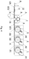
- Fig. 4 shows a device for manufacturing multi-segment rods in a simplified manner.
- the device comprises feeding modules 1, 2, 3, to which rods A1, A2, A3 are fed from feeding units, not shown in the drawing.
- the rods A1, A2, A3 are cut into segments, respectively S1, S2, S3, which are fed onto a transporter 4.
- the machine comprises a feeding module 5, which receives the segments S1, S2, S3 which are fed by the transporter 4 from the feeding modules 1, 2, 3 in a form of a train ST1, wherein the segments S1, S2, S3 are transferred on the transporter 4 wherein spaces are maintained between the segments.
- the feeding unit 5 is equipped with three wheels 6, 7, 8, wherein the wheel 6 receives the segments S1, S2, S3 from the transporter 4 and forms groups G of segments, which are transferred onto the wheel 7 and 8.
- the wheel 8 feeds the segments S1, S2, S3 onto a belt transporter 9, wherein a wrapper 10 is fed on a belt 13 of the belt transporter 9 and the segments S1, S2, S3 are transferred onto the moving wrapper 10 at a point A.
- the linear velocity v2 of the belt 13 is lower than the tangential velocity v1 of the feeding wheel 8, which results in that the gaps between the consecutive groups G of the segments S1, S2, S3 decrease or are completely eliminated.
- the segments S1, S2, S3 transferred on the belt transporter 9 form a train ST2, wherein in the presented embodiment the segments are arranged such that the neighboring segments are in contact which each other.
- the train ST2 of the segments S1 and S2 is wrapped by the wrapper 10, and a glue is fed by means of a glue applicator 19, wherein the gluing of the tape of the wrapper 10 and forming of the continuous rod CR is conducted in a forming unit 11.
- the continuous rod CR thus formed is transferred further and is cut by means of a cutting head 12 into individual multi-segment rods R. Nevertheless some neighbouring segments 1, 2, 3 may be arranged not axially as described in relation to Fig. 2 and 3 . Non axial arrangement of segments may be maintained and faulty rods R may be manufactured.
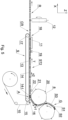
- the transporter 9 comprises a belt 13 and a guide 14, wherein the belt 13 is run between a roller 15 at an inlet side 16 and a roller 17 at an outlet side 18.
- the guide 14 having a form of a bar supports the belt 13, wherein the bar at the inlet side 16 is substantially flat and changes into a centrally rounded guide channel 38 towards the outlet 18 the flat support, adapted in shape to the movement of the belt 13.
- the wrapper may be positioned flat. Due to the varying shape of the guide 14 the wrapper is folded from a horizontal generally flat configuration to a round configuration.
- the feeding wheel 8 of the feeding unit 5 is located above the guide 14, namely located above the inlet part 14-I of the guide 14, at the inlet side of the transporter 9 and is adapted to feed the segments S1, S2, S3 in groups separated by means of pushers 20.
- the segments S1, S2, S3 are transferred in a train ST2 on the transporter 9 to the outlet 18 and further to the cutting head 12 in a form of the continuous rod CR.
- the segments S1, S2, S3 are not arranged coaxially.
- a rotary pushing element 21 having a form of a roller with a cylindrical pushing surface 22.
- the segments S1, S2, S3 are positioned onto the wrapper 10 on the belt 13, wherein at the moment of feeding of the segment, the segment which is being fed is not held, and may rebound up from the surface of the wrapper 10, i.e. in a direction Z.
- the pressing of the segments towards the wrapper 10 and the belt 13 is particularly important in case of long segments S3, because they more easily lose stability in a linear motion and may disturb the flow of the segments.
- the separation of the segment from the wrapper surface would cause breaking the continuity of the ST2 train, resulting in forming of the continuous rod CR, which is not correctly filled and after cutting of such faulty continuous rod, the rods are formed which are further rejected from production, causing decrease of production efficiency.
- the rotary pressing element 21 is intended to press the segment towards the wrapper 10 and to guide the segment from its top during transferring on the transporter 9. In case of the long segments S3 it is advantageous to use two rotary pressing elements 21 arranged directly one after the other.
- the rotary pressing element 21 may be provided with a cylindrical or concave lateral pressing surface.
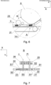
- Fig. 6 shows a fragment of the device for manufacturing multi-segment rods in a second embodiment, wherein two types of rotary pressing elements are used.
- a second rotary pressing element 23 with a concave pressing surface 24 is used, as also shown in Fig. 8 , wherein the curvature of the cross-section of the pressing surface 24 is defined by a radius R.
- Fig. 7 presents the first rotary pressing element 21 and the second rotary pressing element 23 in a top view.
- the first rotary pressing element 21 is mounted on a bearing in a body 25 and rotates about an axis m
- the second rotary pressing element 23 is mounted on a bearing in the body 26 and rotates about an axis n.
- the segment S2 Under the first rotary pressing element 21 the segment S2 is visible, which is pressed in a vertical direction, i.e. in a direction Z, wherein the segment S2 is positioned non-axially with respect to the neighboring segments S1 and S1' (which indicates that the transporter allows non-axial alignment of segments with respect to their neighboring segments).
- the segment S3 Under the second rotary pressing element 23 the segment S3 is visible, that was previously pressed in the Z direction by the first rotary pressing element 21, and subsequently it was positioned axially with respect to the preceding segments S1" and S2', therefore it was positioned axially with respect to the continuous rod CR.
- the segment S3 is guided by three points L1, L2, L3, in other words the second pressing element 23 and the belt 13 of the transporter 9 form a three-point passage for the segments.
- the point L3 is located on the bottom of the channel for the train S2 and the wrapper 10, wherein the channel 38 at the inlet 16 has a form of a small longitudinal recess passing under the train ST2, wherein the rotary pressing element 23 presses the segment S3, wherein the wrapper 10 is sunk in the recess.
- the points L1 and L2 located at edges 24A and 24B are pressing the segment S3 such that the segment S3 is positioned centrally between the points L1 and L2.
- the first rotary pressing element 21 provides correct positioning of the segment S3 in the direction Z.
- the second rotary pressing element 23 provides correct positioning of the segment S3 in the direction Y.
- the segment is positioned in Y direction after the train ST2 is wrapped by the wrapper 10.
- the first rotary pressing element 21 prevents the segments against breaking away from the wrapper 10 and sets the position of the segment in Z direction.
- the second rotary pressing element 23 with concave pressing surface 24 that will position the segments in both directions Z and Y. It should be noticed that in case of using a single rotary pressing element with concave pressing surface having a radius greater than presented on Fig. 8 it is possible to initially position the segments in Y direction over the inlet part 14-I of the guide 14 and the wrapper 10 arranged horizontally and further the segments may be positioned by means of successive pressing elements.
- Fig. 9 shows the positioning of the segment S3 before coming into contact with the second rotary pressing element 23. There is visible a dislocation of the segment to the right in the Y direction such that the segment will firstly come into contact with the edge 24A and will be moved (in Fig. 9 ) to the left in the Y direction until it comes into contact with the edge 24B.
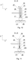
- Fig. 10 shows an embodiment of the second rotary pressing element 27, which comprises two rollers 28 and 29 having concave peripheral pressing surface 30 and 31 defined by the radius R analogously to the rotary pressing element 23.
- Fig. 11 shows an embodiment of the second rotary pressing element 32 comprising two rollers 33 and 34 having peripheral conical pressing surfaces 35 and 36.
- points L1, L2 and L3 forming the three-point passage for the segments. The actual positioning of the points in which the segments come into contact with the wrapper 10 and the rotary pressing element 27, 32 depend on the diameter of the manufactured segments and on possible segments shape errors.
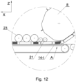
- Fig. 12 shows a fragment of the device for manufacturing multi-segment rods in a third embodiment.
- the device comprises two first rotary pressing elements 21 and three second rotary pressing elements 23.
- the second rotary pressing elements may be arranged consecutively at a smaller and smaller distance from the transporter 9, owing to which the positioning process of the segments in Y direction may be conducted not only by means of one rotary pressing element 23, but consecutively by means of two or three rotary pressing elements 23.
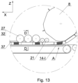
- Fig. 13 shows a fragment of the device for manufacturing multi-segment rods in a fourth embodiment.
- the device comprises two first rotary pressing elements 21 and three second rotary pressing elements 27 or 32.
- the device comprises a stationary pressing element 37, which passes along the transporter 9 between the rollers 28 and 29 or respectively between the rollers 33 and 34.
- the stationary pressing element 37 has a form of a flat bar. Using three different pressing elements allows to gradually press and guide the segments. The segments are guided by means of rotary surfaces and further are stabilized and guided by means of stationary pressing element.
Landscapes
- Engineering & Computer Science (AREA)
- Manufacturing & Machinery (AREA)
- Making Paper Articles (AREA)
- Cigarettes, Filters, And Manufacturing Of Filters (AREA)
- Manufacturing Of Cigar And Cigarette Tobacco (AREA)
- Auxiliary Devices For And Details Of Packaging Control (AREA)
Claims (9)
- Dispositif destiné à la fabrication d'articles en forme de tige à segments multiples (R), le dispositif comprenant :- une unité d'alimentation (5) destinée à l'alimentation d'un train de segments (S1, S2, S3), l'unité d'alimentation (5) comprenant une roue d'alimentation (8),- un transporteur (9) destiné à transporter une enveloppe (10) comportant une forme d'une bande et les segments (S1, S2, S3) sur une courroie (13) le long d'un guide (14) doté d'une partie d'entrée (14-l),- une unité de formation (11) destinée à former une tige continue (CR) à partir des segments (S1, S2, S3),- une tête de coupe (12) destinée à couper la tige continue (CR) en articles individuels en forme de tige à segments multiples (R),- ladite roue d'alimentation (8) étant située au-dessus de la partie d'entrée (14-l) du guide (14),- des éléments de pressage rotatifs (21, 27, 32), comportant chacun une surface de pressage périphérique (22, 30, 31, 35, 36), qui sont positionnés au-dessus de la partie d'entrée (14-l) du guide (14), en aval de la roue d'alimentation (8) et avant l'unité de formation (11) dans une direction de mouvement de la courroie (13), lesdits éléments de pressage rotatifs (21, 27, 32) étant configurés pour régler un alignement axial des segments (S1, S2, S3),- lesdits éléments de pressage rotatifs (21, 27, 32) comprenant :- au moins un premier élément de pressage rotatif (21) avec une surface de pressage cylindrique (22), caractérisé en ce que les éléments de pressage rotatif (21, 27, 32) comprennent en outre :- au moins un second élément de pressage rotatif (27, 32) avec deux rouleaux coaxiaux (28, 29) comportant chacun une surface de pressage concave (30, 31) ou avec deux rouleaux coaxiaux (33, 34) comportant chacun une surface de pressage conique (35, 36).
- Dispositif selon la revendication 1, ledit premier élément de pressage rotatif (21) comportant une forme d'un rouleau avec une surface de pressage cylindrique (22).
- Dispositif selon la revendication 1, ledit second élément de pressage rotatif (27) comportant une forme de deux rouleaux (28, 29), chaque rouleau (28, 29) comportant une surface de pressage concave (30, 31).
- Dispositif selon la revendication 1, ledit second élément de pressage rotatif (32) comportant une forme de deux rouleaux (33, 34), chaque rouleau (33, 34) comportant une surface de pressage conique (35, 36).
- Dispositif selon la revendication 3 ou 4, ledit premier élément de pressage rotatif (21) comportant un diamètre plus petit que le second élément de pressage rotatif (27, 32).
- Dispositif selon la revendication 5, comprenant deux premiers éléments de pressage rotatifs
(21) et trois seconds éléments de pressage rotatifs (27, 32). - Dispositif selon la revendication 6, comprenant un élément de pressage stationnaire longitudinal(37) situé parallèlement à la direction de déplacement de la courroie (13) du transporteur à courroie (9) entre les rouleaux (28,29 ; 33, 34) du second élément de pressage rotatif (27, 32).
- Dispositif selon l'une quelconque des revendications 1 à 7, ladite roue d'alimentation (8) de l'unité d'alimentation (5) étant située au-dessus d'une section d'entrée (16) du transporteur (9).
- Dispositif selon l'une quelconque des revendications 1 à 8, ledit élément de pressage rotatif
(21, 27, 32) étant situé au-dessus de la section d'entrée (16) du transporteur (9).
Applications Claiming Priority (3)
| Application Number | Priority Date | Filing Date | Title |
|---|---|---|---|
| EP20186151 | 2020-07-16 | ||
| EP21185456 | 2021-07-13 | ||
| PCT/EP2021/069913 WO2022013411A1 (fr) | 2020-07-16 | 2021-07-15 | Dispositif de fabrication d'articles en forme de tige à segments multiples |
Publications (2)
| Publication Number | Publication Date |
|---|---|
| EP4181696A1 EP4181696A1 (fr) | 2023-05-24 |
| EP4181696B1 true EP4181696B1 (fr) | 2023-11-15 |
Family
ID=76920794
Family Applications (1)
| Application Number | Title | Priority Date | Filing Date |
|---|---|---|---|
| EP21742149.4A Active EP4181696B1 (fr) | 2020-07-16 | 2021-07-15 | Dispositif de fabrication d'articles en forme de tige à segments multiples |
Country Status (8)
| Country | Link |
|---|---|
| US (1) | US20230263213A1 (fr) |
| EP (1) | EP4181696B1 (fr) |
| JP (1) | JP2023535139A (fr) |
| KR (1) | KR20230039681A (fr) |
| CN (1) | CN116249460A (fr) |
| BR (1) | BR112023000562A2 (fr) |
| PL (1) | PL4181696T3 (fr) |
| WO (1) | WO2022013411A1 (fr) |
Family Cites Families (4)
| Publication number | Priority date | Publication date | Assignee | Title |
|---|---|---|---|---|
| DE2547920A1 (de) * | 1975-10-25 | 1977-04-28 | Hauni Werke Koerber & Co Kg | Verfahren und vorrichtung zum laengsaxialen aneinanderreihen von filterstopfen auf einem huellmaterialstreifen |
| IT1400727B1 (it) * | 2010-07-08 | 2013-07-02 | Gd Spa | Macchina e metodo per la produzione di filtri composti. |
| PL223115B1 (pl) * | 2013-02-15 | 2016-10-31 | Int Tobacco Machinery Poland Spółka Z Ograniczoną Odpowiedzialnością | Sposób, mechanizm i urządzenie do chwilowego kompresowania materiału filtracyjnego |
| PL238487B1 (pl) * | 2013-06-11 | 2021-08-30 | Int Tobacco Machinery Poland Spolka Z Ograniczona Odpowiedzialnoscia | Sposób i stopka do nagniatania segmentów filtra segmentowego |
-
2021
- 2021-07-15 BR BR112023000562A patent/BR112023000562A2/pt unknown
- 2021-07-15 KR KR1020237004443A patent/KR20230039681A/ko unknown
- 2021-07-15 US US18/016,267 patent/US20230263213A1/en active Pending
- 2021-07-15 JP JP2023501476A patent/JP2023535139A/ja active Pending
- 2021-07-15 EP EP21742149.4A patent/EP4181696B1/fr active Active
- 2021-07-15 PL PL21742149.4T patent/PL4181696T3/pl unknown
- 2021-07-15 CN CN202180060904.1A patent/CN116249460A/zh active Pending
- 2021-07-15 WO PCT/EP2021/069913 patent/WO2022013411A1/fr active Application Filing
Also Published As
| Publication number | Publication date |
|---|---|
| JP2023535139A (ja) | 2023-08-16 |
| US20230263213A1 (en) | 2023-08-24 |
| KR20230039681A (ko) | 2023-03-21 |
| PL4181696T3 (pl) | 2024-03-18 |
| CN116249460A (zh) | 2023-06-09 |
| BR112023000562A2 (pt) | 2023-01-31 |
| WO2022013411A1 (fr) | 2022-01-20 |
| EP4181696A1 (fr) | 2023-05-24 |
Similar Documents
| Publication | Publication Date | Title |
|---|---|---|
| US11076635B2 (en) | Method, mechanism and apparatus for momentary compression of filter material | |
| US10111459B2 (en) | Assembly machine for producing cigarettes, and relative assembly method | |
| CN201830890U (zh) | 用于制造可附连于卷烟、雪茄的复合滤嘴的双轨机器 | |
| US8496569B2 (en) | Manufacturing machine for producing combination cigarette filters | |
| CN103491812A (zh) | 烟草加工业的棒形制品的输送 | |
| CN104768404A (zh) | 香烟制造组装机以及相关的组装方法 | |
| EP2717726B1 (fr) | Procédé et machine d'assemblage de filtres pour produire des cigarettes à bout filtre | |
| EP4181696B1 (fr) | Dispositif de fabrication d'articles en forme de tige à segments multiples | |
| KR102430956B1 (ko) | 담배 가공 산업의 실질적으로 실린더형 제품들의 제조 방법 및 장치 | |
| EP2999360B1 (fr) | Appareil destiné à la fabrication d'articles pour fumeur | |
| US3267820A (en) | Manufacture of mouthpiece for cigarettes | |
| EP1413211B1 (fr) | Procédé et dispositif pour assembler des articles à fumer | |
| US10653176B2 (en) | Apparatus for manufacturing of multi-element rods of tobacco industry | |
| US20190183164A1 (en) | Apparatus for manufacturing of multi-element rods of tobacco industry | |
| EP0124289B1 (fr) | Procédé et appareil pour fixer des bout filtrants sur des articles à fumer | |
| PL244277B1 (pl) | Urządzenie do wytwarzania wielosegmentowych artykułów prętopodobnych | |
| CN111615339B (zh) | 用于烟草产业的压紧单元和方法 | |
| US11412778B2 (en) | Feeding device for feeding a continuous strip into a continuous fibrous band in a tobacco industry machine for manufacturing rod-like elements and a machine for manufacturing rod-like elements | |
| US20040221856A1 (en) | Filter tipping machine with double tipping paper feed |
Legal Events
| Date | Code | Title | Description |
|---|---|---|---|
| STAA | Information on the status of an ep patent application or granted ep patent |
Free format text: STATUS: UNKNOWN |
|
| STAA | Information on the status of an ep patent application or granted ep patent |
Free format text: STATUS: THE INTERNATIONAL PUBLICATION HAS BEEN MADE |
|
| PUAI | Public reference made under article 153(3) epc to a published international application that has entered the european phase |
Free format text: ORIGINAL CODE: 0009012 |
|
| STAA | Information on the status of an ep patent application or granted ep patent |
Free format text: STATUS: REQUEST FOR EXAMINATION WAS MADE |
|
| STAA | Information on the status of an ep patent application or granted ep patent |
Free format text: STATUS: EXAMINATION IS IN PROGRESS |
|
| 17P | Request for examination filed |
Effective date: 20230123 |
|
| AK | Designated contracting states |
Kind code of ref document: A1 Designated state(s): AL AT BE BG CH CY CZ DE DK EE ES FI FR GB GR HR HU IE IS IT LI LT LU LV MC MK MT NL NO PL PT RO RS SE SI SK SM TR |
|
| 17Q | First examination report despatched |
Effective date: 20230512 |
|
| GRAP | Despatch of communication of intention to grant a patent |
Free format text: ORIGINAL CODE: EPIDOSNIGR1 |
|
| STAA | Information on the status of an ep patent application or granted ep patent |
Free format text: STATUS: GRANT OF PATENT IS INTENDED |
|
| DAV | Request for validation of the european patent (deleted) | ||
| DAX | Request for extension of the european patent (deleted) | ||
| INTG | Intention to grant announced |
Effective date: 20230831 |
|
| GRAS | Grant fee paid |
Free format text: ORIGINAL CODE: EPIDOSNIGR3 |
|
| GRAA | (expected) grant |
Free format text: ORIGINAL CODE: 0009210 |
|
| STAA | Information on the status of an ep patent application or granted ep patent |
Free format text: STATUS: THE PATENT HAS BEEN GRANTED |
|
| P01 | Opt-out of the competence of the unified patent court (upc) registered |
Effective date: 20230922 |
|
| AK | Designated contracting states |
Kind code of ref document: B1 Designated state(s): AL AT BE BG CH CY CZ DE DK EE ES FI FR GB GR HR HU IE IS IT LI LT LU LV MC MK MT NL NO PL PT RO RS SE SI SK SM TR |
|
| REG | Reference to a national code |
Ref country code: CH Ref legal event code: EP Ref country code: GB Ref legal event code: FG4D |
|
| REG | Reference to a national code |
Ref country code: DE Ref legal event code: R096 Ref document number: 602021006894 Country of ref document: DE |
|
| REG | Reference to a national code |
Ref country code: IE Ref legal event code: FG4D |
|
| REG | Reference to a national code |
Ref country code: LT Ref legal event code: MG9D |
|
| REG | Reference to a national code |
Ref country code: NL Ref legal event code: MP Effective date: 20231115 |
|
| PG25 | Lapsed in a contracting state [announced via postgrant information from national office to epo] |
Ref country code: GR Free format text: LAPSE BECAUSE OF FAILURE TO SUBMIT A TRANSLATION OF THE DESCRIPTION OR TO PAY THE FEE WITHIN THE PRESCRIBED TIME-LIMIT Effective date: 20240216 |
|
| PG25 | Lapsed in a contracting state [announced via postgrant information from national office to epo] |
Ref country code: IS Free format text: LAPSE BECAUSE OF FAILURE TO SUBMIT A TRANSLATION OF THE DESCRIPTION OR TO PAY THE FEE WITHIN THE PRESCRIBED TIME-LIMIT Effective date: 20240315 |
|
| PG25 | Lapsed in a contracting state [announced via postgrant information from national office to epo] |
Ref country code: LT Free format text: LAPSE BECAUSE OF FAILURE TO SUBMIT A TRANSLATION OF THE DESCRIPTION OR TO PAY THE FEE WITHIN THE PRESCRIBED TIME-LIMIT Effective date: 20231115 |
|
| REG | Reference to a national code |
Ref country code: AT Ref legal event code: MK05 Ref document number: 1630897 Country of ref document: AT Kind code of ref document: T Effective date: 20231115 |
|
| PG25 | Lapsed in a contracting state [announced via postgrant information from national office to epo] |
Ref country code: NL Free format text: LAPSE BECAUSE OF FAILURE TO SUBMIT A TRANSLATION OF THE DESCRIPTION OR TO PAY THE FEE WITHIN THE PRESCRIBED TIME-LIMIT Effective date: 20231115 |
|
| PG25 | Lapsed in a contracting state [announced via postgrant information from national office to epo] |
Ref country code: AT Free format text: LAPSE BECAUSE OF FAILURE TO SUBMIT A TRANSLATION OF THE DESCRIPTION OR TO PAY THE FEE WITHIN THE PRESCRIBED TIME-LIMIT Effective date: 20231115 |
|
| PG25 | Lapsed in a contracting state [announced via postgrant information from national office to epo] |
Ref country code: ES Free format text: LAPSE BECAUSE OF FAILURE TO SUBMIT A TRANSLATION OF THE DESCRIPTION OR TO PAY THE FEE WITHIN THE PRESCRIBED TIME-LIMIT Effective date: 20231115 |
|
| PG25 | Lapsed in a contracting state [announced via postgrant information from national office to epo] |
Ref country code: NL Free format text: LAPSE BECAUSE OF FAILURE TO SUBMIT A TRANSLATION OF THE DESCRIPTION OR TO PAY THE FEE WITHIN THE PRESCRIBED TIME-LIMIT Effective date: 20231115 Ref country code: LT Free format text: LAPSE BECAUSE OF FAILURE TO SUBMIT A TRANSLATION OF THE DESCRIPTION OR TO PAY THE FEE WITHIN THE PRESCRIBED TIME-LIMIT Effective date: 20231115 Ref country code: IS Free format text: LAPSE BECAUSE OF FAILURE TO SUBMIT A TRANSLATION OF THE DESCRIPTION OR TO PAY THE FEE WITHIN THE PRESCRIBED TIME-LIMIT Effective date: 20240315 Ref country code: GR Free format text: LAPSE BECAUSE OF FAILURE TO SUBMIT A TRANSLATION OF THE DESCRIPTION OR TO PAY THE FEE WITHIN THE PRESCRIBED TIME-LIMIT Effective date: 20240216 Ref country code: ES Free format text: LAPSE BECAUSE OF FAILURE TO SUBMIT A TRANSLATION OF THE DESCRIPTION OR TO PAY THE FEE WITHIN THE PRESCRIBED TIME-LIMIT Effective date: 20231115 Ref country code: AT Free format text: LAPSE BECAUSE OF FAILURE TO SUBMIT A TRANSLATION OF THE DESCRIPTION OR TO PAY THE FEE WITHIN THE PRESCRIBED TIME-LIMIT Effective date: 20231115 Ref country code: PT Free format text: LAPSE BECAUSE OF FAILURE TO SUBMIT A TRANSLATION OF THE DESCRIPTION OR TO PAY THE FEE WITHIN THE PRESCRIBED TIME-LIMIT Effective date: 20240315 |