EP4181248A1 - Fuel cell apparatus and method for controlling the same - Google Patents
Fuel cell apparatus and method for controlling the same Download PDFInfo
- Publication number
- EP4181248A1 EP4181248A1 EP22205951.1A EP22205951A EP4181248A1 EP 4181248 A1 EP4181248 A1 EP 4181248A1 EP 22205951 A EP22205951 A EP 22205951A EP 4181248 A1 EP4181248 A1 EP 4181248A1
- Authority
- EP
- European Patent Office
- Prior art keywords
- flow path
- air
- cooling water
- reformed gas
- heat exchanger
- Prior art date
- Legal status (The legal status is an assumption and is not a legal conclusion. Google has not performed a legal analysis and makes no representation as to the accuracy of the status listed.)
- Pending
Links
- 239000000446 fuel Substances 0.000 title claims abstract description 130
- 238000000034 method Methods 0.000 title abstract description 8
- 239000000498 cooling water Substances 0.000 claims abstract description 266
- XLYOFNOQVPJJNP-UHFFFAOYSA-N water Substances O XLYOFNOQVPJJNP-UHFFFAOYSA-N 0.000 claims abstract description 147
- 239000007789 gas Substances 0.000 claims description 316
- 238000011084 recovery Methods 0.000 claims description 37
- 238000003487 electrochemical reaction Methods 0.000 claims description 18
- UFHFLCQGNIYNRP-UHFFFAOYSA-N Hydrogen Chemical compound [H][H] UFHFLCQGNIYNRP-UHFFFAOYSA-N 0.000 claims description 13
- 229910052739 hydrogen Inorganic materials 0.000 claims description 10
- 239000001257 hydrogen Substances 0.000 claims description 10
- QVGXLLKOCUKJST-UHFFFAOYSA-N atomic oxygen Chemical compound [O] QVGXLLKOCUKJST-UHFFFAOYSA-N 0.000 claims description 8
- 229910052760 oxygen Inorganic materials 0.000 claims description 8
- 239000001301 oxygen Substances 0.000 claims description 8
- 238000010248 power generation Methods 0.000 description 45
- 238000002485 combustion reaction Methods 0.000 description 24
- 238000012545 processing Methods 0.000 description 20
- 239000002737 fuel gas Substances 0.000 description 15
- 238000002407 reforming Methods 0.000 description 14
- UGFAIRIUMAVXCW-UHFFFAOYSA-N Carbon monoxide Chemical compound [O+]#[C-] UGFAIRIUMAVXCW-UHFFFAOYSA-N 0.000 description 11
- 229910002091 carbon monoxide Inorganic materials 0.000 description 11
- 238000012546 transfer Methods 0.000 description 9
- 238000010586 diagram Methods 0.000 description 8
- 238000013021 overheating Methods 0.000 description 6
- 238000006057 reforming reaction Methods 0.000 description 5
- 239000000126 substance Substances 0.000 description 5
- 239000003054 catalyst Substances 0.000 description 4
- LFQSCWFLJHTTHZ-UHFFFAOYSA-N Ethanol Chemical compound CCO LFQSCWFLJHTTHZ-UHFFFAOYSA-N 0.000 description 3
- OKKJLVBELUTLKV-UHFFFAOYSA-N Methanol Chemical compound OC OKKJLVBELUTLKV-UHFFFAOYSA-N 0.000 description 3
- PXHVJJICTQNCMI-UHFFFAOYSA-N Nickel Chemical compound [Ni] PXHVJJICTQNCMI-UHFFFAOYSA-N 0.000 description 3
- 238000007792 addition Methods 0.000 description 3
- 239000003463 adsorbent Substances 0.000 description 3
- 238000001816 cooling Methods 0.000 description 3
- 239000012528 membrane Substances 0.000 description 3
- 230000004048 modification Effects 0.000 description 3
- 238000012986 modification Methods 0.000 description 3
- 230000006641 stabilisation Effects 0.000 description 3
- 238000011105 stabilization Methods 0.000 description 3
- OKTJSMMVPCPJKN-UHFFFAOYSA-N Carbon Chemical compound [C] OKTJSMMVPCPJKN-UHFFFAOYSA-N 0.000 description 2
- CURLTUGMZLYLDI-UHFFFAOYSA-N Carbon dioxide Chemical compound O=C=O CURLTUGMZLYLDI-UHFFFAOYSA-N 0.000 description 2
- PNEYBMLMFCGWSK-UHFFFAOYSA-N aluminium oxide Inorganic materials [O-2].[O-2].[O-2].[Al+3].[Al+3] PNEYBMLMFCGWSK-UHFFFAOYSA-N 0.000 description 2
- 238000006243 chemical reaction Methods 0.000 description 2
- 230000005611 electricity Effects 0.000 description 2
- 239000003792 electrolyte Substances 0.000 description 2
- 239000007788 liquid Substances 0.000 description 2
- VNWKTOKETHGBQD-UHFFFAOYSA-N methane Chemical compound C VNWKTOKETHGBQD-UHFFFAOYSA-N 0.000 description 2
- 239000000203 mixture Substances 0.000 description 2
- 230000003647 oxidation Effects 0.000 description 2
- 238000007254 oxidation reaction Methods 0.000 description 2
- 238000006467 substitution reaction Methods 0.000 description 2
- 239000004215 Carbon black (E152) Substances 0.000 description 1
- 229910021536 Zeolite Inorganic materials 0.000 description 1
- 229910002092 carbon dioxide Inorganic materials 0.000 description 1
- 239000001569 carbon dioxide Substances 0.000 description 1
- 238000009833 condensation Methods 0.000 description 1
- 230000005494 condensation Effects 0.000 description 1
- 229910052593 corundum Inorganic materials 0.000 description 1
- 238000006477 desulfuration reaction Methods 0.000 description 1
- 230000023556 desulfurization Effects 0.000 description 1
- HNPSIPDUKPIQMN-UHFFFAOYSA-N dioxosilane;oxo(oxoalumanyloxy)alumane Chemical compound O=[Si]=O.O=[Al]O[Al]=O HNPSIPDUKPIQMN-UHFFFAOYSA-N 0.000 description 1
- 238000007599 discharging Methods 0.000 description 1
- 230000000694 effects Effects 0.000 description 1
- 238000005516 engineering process Methods 0.000 description 1
- -1 for example Substances 0.000 description 1
- 229930195733 hydrocarbon Natural products 0.000 description 1
- 150000002430 hydrocarbons Chemical class 0.000 description 1
- 150000002431 hydrogen Chemical class 0.000 description 1
- 125000004435 hydrogen atom Chemical group [H]* 0.000 description 1
- 229910044991 metal oxide Inorganic materials 0.000 description 1
- 150000004706 metal oxides Chemical class 0.000 description 1
- 239000003345 natural gas Substances 0.000 description 1
- 229910052759 nickel Inorganic materials 0.000 description 1
- 230000001151 other effect Effects 0.000 description 1
- 230000005855 radiation Effects 0.000 description 1
- 230000003134 recirculating effect Effects 0.000 description 1
- 238000004904 shortening Methods 0.000 description 1
- 150000003464 sulfur compounds Chemical class 0.000 description 1
- 229910021642 ultra pure water Inorganic materials 0.000 description 1
- 239000012498 ultrapure water Substances 0.000 description 1
- 239000002918 waste heat Substances 0.000 description 1
- 229910001845 yogo sapphire Inorganic materials 0.000 description 1
- 239000010457 zeolite Substances 0.000 description 1
Images




Classifications
-
- H—ELECTRICITY
- H01—ELECTRIC ELEMENTS
- H01M—PROCESSES OR MEANS, e.g. BATTERIES, FOR THE DIRECT CONVERSION OF CHEMICAL ENERGY INTO ELECTRICAL ENERGY
- H01M8/00—Fuel cells; Manufacture thereof
- H01M8/04—Auxiliary arrangements, e.g. for control of pressure or for circulation of fluids
- H01M8/04298—Processes for controlling fuel cells or fuel cell systems
- H01M8/04694—Processes for controlling fuel cells or fuel cell systems characterised by variables to be controlled
- H01M8/04746—Pressure; Flow
- H01M8/04753—Pressure; Flow of fuel cell reactants
-
- H—ELECTRICITY
- H01—ELECTRIC ELEMENTS
- H01M—PROCESSES OR MEANS, e.g. BATTERIES, FOR THE DIRECT CONVERSION OF CHEMICAL ENERGY INTO ELECTRICAL ENERGY
- H01M8/00—Fuel cells; Manufacture thereof
- H01M8/04—Auxiliary arrangements, e.g. for control of pressure or for circulation of fluids
- H01M8/04007—Auxiliary arrangements, e.g. for control of pressure or for circulation of fluids related to heat exchange
- H01M8/04014—Heat exchange using gaseous fluids; Heat exchange by combustion of reactants
-
- H—ELECTRICITY
- H01—ELECTRIC ELEMENTS
- H01M—PROCESSES OR MEANS, e.g. BATTERIES, FOR THE DIRECT CONVERSION OF CHEMICAL ENERGY INTO ELECTRICAL ENERGY
- H01M8/00—Fuel cells; Manufacture thereof
- H01M8/04—Auxiliary arrangements, e.g. for control of pressure or for circulation of fluids
- H01M8/04007—Auxiliary arrangements, e.g. for control of pressure or for circulation of fluids related to heat exchange
- H01M8/04014—Heat exchange using gaseous fluids; Heat exchange by combustion of reactants
- H01M8/04022—Heating by combustion
-
- H—ELECTRICITY
- H01—ELECTRIC ELEMENTS
- H01M—PROCESSES OR MEANS, e.g. BATTERIES, FOR THE DIRECT CONVERSION OF CHEMICAL ENERGY INTO ELECTRICAL ENERGY
- H01M8/00—Fuel cells; Manufacture thereof
- H01M8/04—Auxiliary arrangements, e.g. for control of pressure or for circulation of fluids
- H01M8/04007—Auxiliary arrangements, e.g. for control of pressure or for circulation of fluids related to heat exchange
- H01M8/04029—Heat exchange using liquids
-
- H—ELECTRICITY
- H01—ELECTRIC ELEMENTS
- H01M—PROCESSES OR MEANS, e.g. BATTERIES, FOR THE DIRECT CONVERSION OF CHEMICAL ENERGY INTO ELECTRICAL ENERGY
- H01M8/00—Fuel cells; Manufacture thereof
- H01M8/04—Auxiliary arrangements, e.g. for control of pressure or for circulation of fluids
- H01M8/04007—Auxiliary arrangements, e.g. for control of pressure or for circulation of fluids related to heat exchange
- H01M8/04067—Heat exchange or temperature measuring elements, thermal insulation, e.g. heat pipes, heat pumps, fins
- H01M8/04074—Heat exchange unit structures specially adapted for fuel cell
-
- H—ELECTRICITY
- H01—ELECTRIC ELEMENTS
- H01M—PROCESSES OR MEANS, e.g. BATTERIES, FOR THE DIRECT CONVERSION OF CHEMICAL ENERGY INTO ELECTRICAL ENERGY
- H01M8/00—Fuel cells; Manufacture thereof
- H01M8/04—Auxiliary arrangements, e.g. for control of pressure or for circulation of fluids
- H01M8/04082—Arrangements for control of reactant parameters, e.g. pressure or concentration
- H01M8/04089—Arrangements for control of reactant parameters, e.g. pressure or concentration of gaseous reactants
-
- H—ELECTRICITY
- H01—ELECTRIC ELEMENTS
- H01M—PROCESSES OR MEANS, e.g. BATTERIES, FOR THE DIRECT CONVERSION OF CHEMICAL ENERGY INTO ELECTRICAL ENERGY
- H01M8/00—Fuel cells; Manufacture thereof
- H01M8/04—Auxiliary arrangements, e.g. for control of pressure or for circulation of fluids
- H01M8/04082—Arrangements for control of reactant parameters, e.g. pressure or concentration
- H01M8/04201—Reactant storage and supply, e.g. means for feeding, pipes
-
- H—ELECTRICITY
- H01—ELECTRIC ELEMENTS
- H01M—PROCESSES OR MEANS, e.g. BATTERIES, FOR THE DIRECT CONVERSION OF CHEMICAL ENERGY INTO ELECTRICAL ENERGY
- H01M8/00—Fuel cells; Manufacture thereof
- H01M8/04—Auxiliary arrangements, e.g. for control of pressure or for circulation of fluids
- H01M8/04223—Auxiliary arrangements, e.g. for control of pressure or for circulation of fluids during start-up or shut-down; Depolarisation or activation, e.g. purging; Means for short-circuiting defective fuel cells
- H01M8/04225—Auxiliary arrangements, e.g. for control of pressure or for circulation of fluids during start-up or shut-down; Depolarisation or activation, e.g. purging; Means for short-circuiting defective fuel cells during start-up
-
- H—ELECTRICITY
- H01—ELECTRIC ELEMENTS
- H01M—PROCESSES OR MEANS, e.g. BATTERIES, FOR THE DIRECT CONVERSION OF CHEMICAL ENERGY INTO ELECTRICAL ENERGY
- H01M8/00—Fuel cells; Manufacture thereof
- H01M8/04—Auxiliary arrangements, e.g. for control of pressure or for circulation of fluids
- H01M8/04223—Auxiliary arrangements, e.g. for control of pressure or for circulation of fluids during start-up or shut-down; Depolarisation or activation, e.g. purging; Means for short-circuiting defective fuel cells
- H01M8/04268—Heating of fuel cells during the start-up of the fuel cells
-
- H—ELECTRICITY
- H01—ELECTRIC ELEMENTS
- H01M—PROCESSES OR MEANS, e.g. BATTERIES, FOR THE DIRECT CONVERSION OF CHEMICAL ENERGY INTO ELECTRICAL ENERGY
- H01M8/00—Fuel cells; Manufacture thereof
- H01M8/04—Auxiliary arrangements, e.g. for control of pressure or for circulation of fluids
- H01M8/04298—Processes for controlling fuel cells or fuel cell systems
- H01M8/043—Processes for controlling fuel cells or fuel cell systems applied during specific periods
- H01M8/04302—Processes for controlling fuel cells or fuel cell systems applied during specific periods applied during start-up
-
- H—ELECTRICITY
- H01—ELECTRIC ELEMENTS
- H01M—PROCESSES OR MEANS, e.g. BATTERIES, FOR THE DIRECT CONVERSION OF CHEMICAL ENERGY INTO ELECTRICAL ENERGY
- H01M8/00—Fuel cells; Manufacture thereof
- H01M8/04—Auxiliary arrangements, e.g. for control of pressure or for circulation of fluids
- H01M8/04298—Processes for controlling fuel cells or fuel cell systems
- H01M8/04313—Processes for controlling fuel cells or fuel cell systems characterised by the detection or assessment of variables; characterised by the detection or assessment of failure or abnormal function
- H01M8/0432—Temperature; Ambient temperature
- H01M8/04328—Temperature; Ambient temperature of anode reactants at the inlet or inside the fuel cell
-
- H—ELECTRICITY
- H01—ELECTRIC ELEMENTS
- H01M—PROCESSES OR MEANS, e.g. BATTERIES, FOR THE DIRECT CONVERSION OF CHEMICAL ENERGY INTO ELECTRICAL ENERGY
- H01M8/00—Fuel cells; Manufacture thereof
- H01M8/04—Auxiliary arrangements, e.g. for control of pressure or for circulation of fluids
- H01M8/04298—Processes for controlling fuel cells or fuel cell systems
- H01M8/04313—Processes for controlling fuel cells or fuel cell systems characterised by the detection or assessment of variables; characterised by the detection or assessment of failure or abnormal function
- H01M8/0432—Temperature; Ambient temperature
- H01M8/04335—Temperature; Ambient temperature of cathode reactants at the inlet or inside the fuel cell
-
- H—ELECTRICITY
- H01—ELECTRIC ELEMENTS
- H01M—PROCESSES OR MEANS, e.g. BATTERIES, FOR THE DIRECT CONVERSION OF CHEMICAL ENERGY INTO ELECTRICAL ENERGY
- H01M8/00—Fuel cells; Manufacture thereof
- H01M8/04—Auxiliary arrangements, e.g. for control of pressure or for circulation of fluids
- H01M8/04298—Processes for controlling fuel cells or fuel cell systems
- H01M8/04313—Processes for controlling fuel cells or fuel cell systems characterised by the detection or assessment of variables; characterised by the detection or assessment of failure or abnormal function
- H01M8/0432—Temperature; Ambient temperature
- H01M8/04358—Temperature; Ambient temperature of the coolant
-
- H—ELECTRICITY
- H01—ELECTRIC ELEMENTS
- H01M—PROCESSES OR MEANS, e.g. BATTERIES, FOR THE DIRECT CONVERSION OF CHEMICAL ENERGY INTO ELECTRICAL ENERGY
- H01M8/00—Fuel cells; Manufacture thereof
- H01M8/04—Auxiliary arrangements, e.g. for control of pressure or for circulation of fluids
- H01M8/04298—Processes for controlling fuel cells or fuel cell systems
- H01M8/04313—Processes for controlling fuel cells or fuel cell systems characterised by the detection or assessment of variables; characterised by the detection or assessment of failure or abnormal function
- H01M8/0432—Temperature; Ambient temperature
- H01M8/04373—Temperature; Ambient temperature of auxiliary devices, e.g. reformers, compressors, burners
-
- H—ELECTRICITY
- H01—ELECTRIC ELEMENTS
- H01M—PROCESSES OR MEANS, e.g. BATTERIES, FOR THE DIRECT CONVERSION OF CHEMICAL ENERGY INTO ELECTRICAL ENERGY
- H01M8/00—Fuel cells; Manufacture thereof
- H01M8/04—Auxiliary arrangements, e.g. for control of pressure or for circulation of fluids
- H01M8/04298—Processes for controlling fuel cells or fuel cell systems
- H01M8/04694—Processes for controlling fuel cells or fuel cell systems characterised by variables to be controlled
- H01M8/04746—Pressure; Flow
- H01M8/04768—Pressure; Flow of the coolant
-
- H—ELECTRICITY
- H01—ELECTRIC ELEMENTS
- H01M—PROCESSES OR MEANS, e.g. BATTERIES, FOR THE DIRECT CONVERSION OF CHEMICAL ENERGY INTO ELECTRICAL ENERGY
- H01M8/00—Fuel cells; Manufacture thereof
- H01M8/04—Auxiliary arrangements, e.g. for control of pressure or for circulation of fluids
- H01M8/04298—Processes for controlling fuel cells or fuel cell systems
- H01M8/04694—Processes for controlling fuel cells or fuel cell systems characterised by variables to be controlled
- H01M8/04746—Pressure; Flow
- H01M8/04776—Pressure; Flow at auxiliary devices, e.g. reformer, compressor, burner
-
- H—ELECTRICITY
- H01—ELECTRIC ELEMENTS
- H01M—PROCESSES OR MEANS, e.g. BATTERIES, FOR THE DIRECT CONVERSION OF CHEMICAL ENERGY INTO ELECTRICAL ENERGY
- H01M8/00—Fuel cells; Manufacture thereof
- H01M8/04—Auxiliary arrangements, e.g. for control of pressure or for circulation of fluids
- H01M8/04298—Processes for controlling fuel cells or fuel cell systems
- H01M8/04694—Processes for controlling fuel cells or fuel cell systems characterised by variables to be controlled
- H01M8/04955—Shut-off or shut-down of fuel cells
-
- H—ELECTRICITY
- H01—ELECTRIC ELEMENTS
- H01M—PROCESSES OR MEANS, e.g. BATTERIES, FOR THE DIRECT CONVERSION OF CHEMICAL ENERGY INTO ELECTRICAL ENERGY
- H01M8/00—Fuel cells; Manufacture thereof
- H01M8/06—Combination of fuel cells with means for production of reactants or for treatment of residues
- H01M8/0606—Combination of fuel cells with means for production of reactants or for treatment of residues with means for production of gaseous reactants
- H01M8/0612—Combination of fuel cells with means for production of reactants or for treatment of residues with means for production of gaseous reactants from carbon-containing material
- H01M8/0618—Reforming processes, e.g. autothermal, partial oxidation or steam reforming
-
- H—ELECTRICITY
- H01—ELECTRIC ELEMENTS
- H01M—PROCESSES OR MEANS, e.g. BATTERIES, FOR THE DIRECT CONVERSION OF CHEMICAL ENERGY INTO ELECTRICAL ENERGY
- H01M8/00—Fuel cells; Manufacture thereof
- H01M8/06—Combination of fuel cells with means for production of reactants or for treatment of residues
- H01M8/0662—Treatment of gaseous reactants or gaseous residues, e.g. cleaning
-
- H—ELECTRICITY
- H01—ELECTRIC ELEMENTS
- H01M—PROCESSES OR MEANS, e.g. BATTERIES, FOR THE DIRECT CONVERSION OF CHEMICAL ENERGY INTO ELECTRICAL ENERGY
- H01M8/00—Fuel cells; Manufacture thereof
- H01M8/24—Grouping of fuel cells, e.g. stacking of fuel cells
- H01M8/2457—Grouping of fuel cells, e.g. stacking of fuel cells with both reactants being gaseous or vaporised
-
- H—ELECTRICITY
- H01—ELECTRIC ELEMENTS
- H01M—PROCESSES OR MEANS, e.g. BATTERIES, FOR THE DIRECT CONVERSION OF CHEMICAL ENERGY INTO ELECTRICAL ENERGY
- H01M2250/00—Fuel cells for particular applications; Specific features of fuel cell system
- H01M2250/40—Combination of fuel cells with other energy production systems
- H01M2250/405—Cogeneration of heat or hot water
-
- H—ELECTRICITY
- H01—ELECTRIC ELEMENTS
- H01M—PROCESSES OR MEANS, e.g. BATTERIES, FOR THE DIRECT CONVERSION OF CHEMICAL ENERGY INTO ELECTRICAL ENERGY
- H01M8/00—Fuel cells; Manufacture thereof
- H01M8/24—Grouping of fuel cells, e.g. stacking of fuel cells
- H01M8/249—Grouping of fuel cells, e.g. stacking of fuel cells comprising two or more groupings of fuel cells, e.g. modular assemblies
-
- Y—GENERAL TAGGING OF NEW TECHNOLOGICAL DEVELOPMENTS; GENERAL TAGGING OF CROSS-SECTIONAL TECHNOLOGIES SPANNING OVER SEVERAL SECTIONS OF THE IPC; TECHNICAL SUBJECTS COVERED BY FORMER USPC CROSS-REFERENCE ART COLLECTIONS [XRACs] AND DIGESTS
- Y02—TECHNOLOGIES OR APPLICATIONS FOR MITIGATION OR ADAPTATION AGAINST CLIMATE CHANGE
- Y02E—REDUCTION OF GREENHOUSE GAS [GHG] EMISSIONS, RELATED TO ENERGY GENERATION, TRANSMISSION OR DISTRIBUTION
- Y02E60/00—Enabling technologies; Technologies with a potential or indirect contribution to GHG emissions mitigation
- Y02E60/30—Hydrogen technology
- Y02E60/50—Fuel cells
Definitions
- the present disclosure relates to a fuel cell apparatus and a method for controlling the same, and more particularly, to a fuel cell apparatus which may control the temperatures of cooling water and reformed gas using a vertex tube.
- a fuel cell apparatus is a power generation apparatus which generates electrical energy through an electrochemical reaction between hydrogen included in a hydrocarbon-based substance, for example, methanol, ethanol, natural gas or the like, and oxygen.
- a hydrocarbon-based substance for example, methanol, ethanol, natural gas or the like, and oxygen.
- the conventional fuel cell apparatus includes, in a similar manner to a fuel cell system disclosed in Related Art Document 1 ( Korean Patent Unexamined Publication No. 10-2012-0071288 ), a fuel processor configured to reform fuel including hydrogen atoms into hydrogen gas, and a stack configured to generate electrical energy using hydrogen gas supplied from the fuel processor. Further, the conventional fuel cell apparatus may further include a heat exchanger and a cooling water pipe line configured to cool the stack and to recover heat, and a power converter configured to convert produced DC power into AC power.
- the fuel cell apparatus includes a blower configured to blow external air to the fuel processor or the stack, in a similar manner to a fuel cell system disclosed in Related Art Document 2 ( Korean Patent Registration No. 10-1951439 ).
- the conventional fuel cell apparatus may be first operated in a preheating mode in which a reformer configured to generate reformed gas necessary to generate electricity in the stack using fuel gas is preheated to a temperature suitable for reforming by the burner, may be operated in a reforming mode in which reforming is repeated while recirculating the reformed gas generated by the reformer to the burner until hydrogen, carbon monoxide, etc. in the generated reformed gas reach concentrations suitable for power generation in the stack, when the reformer reaches the above temperature condition, and may be operated in a power generation mode in which the reformed gas and external air are supplied to the stack so as to produce electrical energy through the electrochemical reaction, when the reformed gas reaches the above concentration condition.
- the stack generally exhibits the maximum power generation efficiency at a temperature of about 75°C, the stack starts to be preheated due to supply of the high-temperature reformed gas and the cooling water heated through heat exchange with the reformed gas only when the conventional fuel cell apparatus enters power generation operation, and thus, the temperature of the stack is low and thus power generation efficiency is low at the initial stage of the power generation operation of the fuel cell apparatus.
- the stack generates heat depending on the power generation operation of the fuel cell apparatus, and such heat enables the stack to reach a temperature suitable for power generation at the initial stage of the power generation operation of the fuel cell apparatus, but needs to be radiated so as to prevent the stack from overheating after the stack reaches a target temperature.
- a fuel cell apparatus includes a stack, a reformer configured to generate reformed gas and to supply the reformed gas to the stack, a burner configured to heat the reformer, a water supply tank configured to store cooling water supplied to the stack, a burner air blower configured to draw in external air and then to blow the air, a vertex tube configured to convert the air into heated air and cooled air, and a three-way valve configured to supply the air blown from the burner air blower selectively to the vertex tube or the burner.
- the fuel cell apparatus may further include a first heat exchanger configured to exchange heat between the air discharged from the vertex tube and the cooling water supplied from the water supply tank to the stack and then to supply the air to the burner, a second heat exchanger configured to exchange heat between the air discharged from the vertex tube and the reformed gas discharged from the reformer and then to supply the air to the burner, and a four-way valve configured to supply the heated air and the cooled air discharged from the vertex tube to different ones out of the first heat exchanger and the second exchanger.
- the four-way valve may be configured to discharge the heated air to one of a first switch flow path and a second switch flow path, and to discharge the cooled air to the other one of the first switch flow path and the second switch flow path;
- the fuel cell apparatus may further include a reformed gas bypass flow path configured to allow the reformed gas discharged from the reformer and having passed through the second heat exchanger to be supplied to the burner, and a reformed gas bypass valve disposed on the reformed gas bypass flow path so as to be opened and closed.
- the preheated cooling water may transfer heat to the stack, and may thus rapidly preheat the stack to a temperature suitable for power generation.
- the reformed gas generated by the reformer and discharged therefrom is cooled through heat exchange with the cooled air in the second heat exchanger and is then supplied to the burner or the stack
- the reformed gas having an improved density may be supplied to the burner or the stack, and may thus improve combustion efficiency of the burner or power generation efficiency of the stack.
- the three-way valve may be switched so as to prevent unnecessary heat exchange between the cooling water and the reformed gas reaching temperatures suitable for power generation in the first and second heat exchanger, and thus, air blown from the burner air blower may be supplied to the burner rather than the vertex tube, the optimum temperatures of the cooling water and the reformed gas may be maintained, and high power generation efficiency of the stack may be maintained.
- the fuel cell apparatus may further include a reformed gas heat exchanger configured to exchange heat between the cooling water having exchanged heat while passing through the first heat exchanger and the reformed gas having exchanged heat while passing through the second heat exchanger and then to supply the cooling water and the reformed gas to the stack, a first bypass flow path configured to allow the air supplied from the vertex tube to the first heat exchanger to bypass the first heat exchanger, a first bypass valve disposed on the first bypass flow path and configured to be opened and closed, a second bypass flow path configured to allow the air supplied from the vertex tube to the second heat exchanger to bypass the second heat exchanger, and a second bypass valve disposed on the second bypass flow path and configured to be opened and closed.
- a reformed gas heat exchanger configured to exchange heat between the cooling water having exchanged heat while passing through the first heat exchanger and the reformed gas having exchanged heat while passing through the second heat exchanger and then to supply the cooling water and the reformed gas to the stack
- a first bypass flow path configured to allow the air
- the reformed gas may be supplied to the reformed gas heat exchanger without heat loss so as to exchange heat with the cooling water, and may thus effectively preheat the cooling water passing through the reformed gas heat exchanger.
- the first bypass valve may be opened so as not to supply the heated air to the first heat exchanger or the four-way valve may be switched so as not to supply the cooled air to the first heat exchanger, and may prevent the cooling water passing through the first heat exchanger from being preheated or allow the cooling water to be cooled, and therefore, the cooling water may maintain a proper temperature without overheating.
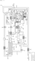
- the fuel cell apparatus 1 may include a fuel processor I, a power generator II, a water circulator III and/or a heat recoverer IV.
- the fuel cell apparatus 1 may further include a power converter (not shown) including a power conversion device configured to convert DC power produced by the power generator II into AC power.
- the fuel processor I may include a fuel processing device 10, a fuel valve 30 configured to control the flow of fuel gas supplied to the fuel processing device 10, and a burner air blower 71 configured to blow air to the fuel processing device 10.
- the power generator II may include stacks 20a and 20b, a reformed gas heat exchanger 21 configured to exchange heat with reformed gas discharged from the fuel processing device 10, a fifth heat exchanger 22 configured to exchange heat with unreacted gas discharged from the stacks 20a and 20b, a humidifier 23 configured to supply moisture to air supplied to the stacks 20a and 20b, and a stack air blower 72 configured to blow air to the stacks 20a and 20b.
- the unreacted gas discharged from the stacks 20a and 20b may be referred to as anode off-gas (AOG).
- AOG anode off-gas
- the present disclosure illustrates that the fuel cell apparatus 1 includes two stacks 20a and 20b, the present disclosure is not limited to the number of stacks.
- the water circulator III may include a water supply tank 13 configured to store water produced by the fuel cell apparatus 1, a water pump 38 configured to pump water to the fuel processing device 10, a water supply valve 39 configured to control the flow of water supplied to the fuel processing device 10, and a cooling water pump 43 configured to pump water to the reformed gas heat exchanger 21.
- the heat recoverer IV may include a heat recovery tank 15 configured to store water used in heat exchange, and a hot water pump 48 configured to pump water stored in the heat recovery tank 15 to the outside of the heat recovery tank 15.
- the fuel cell apparatus 1 includes the stacks 20a and 20b, a reformer 140 configured to generate reformed gas and then to supply the reformed gas to the stacks 20a and 20b, a burner 120 configured to heat the reformer 140, the water supply tank 13 configured to store the cooling water supplied to the stacks 20a and 20b, the burner air blower 71 configured to draw in external air and then to supply the air to the burner 120, a vortex tube 502 configured to convert air into heated air and cooled air, and a three-way valve 500 configured to supply the air blown from the burner air blower 71 selectively to the vortex tube 502 or the burner 120.
- the fuel cell apparatus 1 includes a first heat exchanger 510 configured to exchange heat between the air discharged from the vertex tube 502 and the cooling water supplied from the water supply tank 13 to the stacks 20a and 20b and then to supply the air to the burner 120, a second heat exchanger 520 configured to exchange heat between the air discharged from the vertex tube 502 and the reformed gas discharged from the reformer 140 and then to supply the air to the burner 120, and a four-way valve 505 configured to supply the heated air and the cooled air discharged from the vertex tube 502 to different ones out of the first heat exchanger 510 and the second heat exchanger 520.
- a first heat exchanger 510 configured to exchange heat between the air discharged from the vertex tube 502 and the cooling water supplied from the water supply tank 13 to the stacks 20a and 20b and then to supply the air to the burner 120
- a second heat exchanger 520 configured to exchange heat between the air discharged from the vertex tube 502 and the reformed gas discharged from the reformer 140
- the stacks 20a and 20b may generate electrical energy through an electrochemical reaction between hydrogen and oxygen.
- the stacks 20a and 20b may generate electrical energy through the electrochemical reaction between hydrogen included in the reformed gas supplied from the fuel processing device 10 and oxygen supplied from external air.
- the stacks 20a and 20b may be formed by stacking unit cells in which the electrochemical reaction occurs.
- Each unit cell may include a membrane electrode assembly (MEA) including an electrolyte membrane and an anode and a cathode disposed on both surfaces of the electrolyte membrane, separators, etc.
- MEA membrane electrode assembly
- Hydrogen may be separated into protons and electrons by a catalyst so as to generate electricity at the anode of the MEA, and protons and electrons may be combined with oxygen so as to produce water at the cathode of the MEA.
- the reformer 140 may generate reformed gas by reforming fuel gas, and may supply the reformed gas to the stacks 20a and 20b.
- the reformer 140 may perform a reforming process for generating hydrogen gas from fuel gas, from which sulfur compounds are removed, using a catalyst.
- the catalyst used in the reforming process may be a catalyst including nickel (Ni), alumina (Al 2 O 3 ) or the like.
- the fuel gas discharged from a desulfurizer 110 and steam discharged from a steam generator 130 may be mixed in a second mixer 112, and may be supplied to the reformer 140.
- hydrogen gas may be generated.
- Gas discharged from the reformer 140 may be referred to as reformed gas.
- the burner 120 may heat the reformer 140 so as to promote the reforming reaction in the reformer 140.
- the fuel gas discharged from the desulfurizer 110 and air introduced from the outside may be mixed in a first mixer 111, and may be supplied to the burner 120.
- the burner 120 may produce combustion heat through combustion of a mixture of the fuel gas and air supplied from the outside, and the reformer 140 may maintain a proper inner temperature (for example, 800°C) due to heat supplied by the burner 120.
- Exhaust gas generated by the burner 120 due to combustion of the mixture of the fuel gas and air may be discharged to the outside of the fuel processing device 10.
- the exhaust gas generated by the burner 120 of the fuel processing device 10 may be discharged from the fuel processing device 10 through an exhaust gas discharge flow path 210, may be supplied to a third heat exchanger 26, may exchange heat, and may then be discharged to the outside.
- the burner air blower 71 may draw in external air and discharge the air.
- the burner air blower 71 may be connected to a first external air inflow path 201, and may draw in external air introduced through the first external air inflow path 201.
- the burner air blower 71 may be connected to an outflow path 201a, and may discharge the drawn external air.
- the outflow path 201a may connect an outlet of the burner air blower 71 to an inlet of the three-way valve 500.
- the three-way valve 500 may supply air discharged from the burner air blower 71 selectively to a main air supply flow path 202 or the vertex tube 502.
- the three-way valve 500 may be connected to the outflow path 201a, the main air supply flow path 202 and a vertex air supply flow path 501 in three directions.
- the three-way valve 500 may receive air discharged from the burner air blower 71 through the outflow path 201a.
- the three-way valve 500 may be switched to discharge the received air to the main air supply flow path 202 or to the vertex air supply flow path 501.
- the vertex air supply flow path 501 may connect one outlet of the three-way valve 500 to an inlet of the vertex tube 502.
- the main air supply flow path 202 may connect another outlet of the three-way valve 500 to the fuel processing device 100, and may supply air discharged from the burner air blower 71 to the burner 120.
- air supplied to the fuel processing device 10 through the main air supply flow path 202 may be mixed with fuel gas discharged from the desulfurizer 110 in the first mixer 111, and may be supplied to the burner 120.
- the vertex tube 502 may convert the air discharged from the burner air blower 71 into heated air and cooled air.
- an inlet of the vertex tube 502 may be connected to the vertex air supply flow path 501, and the vertex tube 502 may receive air through the vertex air supply flow path 501 and convert the received air into heated air and cooled air.
- a heated air outlet of the vertex tube 502 may be connected to a hot air supply flow path 503, and thus, the heated air converted by the vertex tube 502 may be discharged through the hot air supply flow path 503.
- a cooled air outlet of the vertex tube 502 may be connected to a cold air supply flow path 504, and thus, the cooled air converted by the vertex tube 502 may be discharged through the cold air supply flow path 504.
- the hot air supply flow path 503 may connect the heated air outlet of the vertex tube 502 to the four-way valve 505, and may supply the heated air discharged from the vertex tube 502 to the four-way valve 505.
- the cold air supply flow path 504 may connect the cooled air outlet of the vertex tube 502 to the four-way valve 505.
- the cold air supply flow path 504 may supply the cooled air discharged from the vertex tube 502 to the four-way valve 505.
- the four-way valve 505 enables the heated air and the cooled air discharged from the vertex tube 502 to be discharged to different ones out of a first switch flow path 511 and a second switch flow path 521.
- the four-way valve 505 may be connected to the hot air supply flow path 503, the cold air supply flow path 504, the first switch flow path 511 and the second switch flow path 521 in four directions.
- the four-way valve 505 may be switched to discharge the heated air supplied through the hot air supply flow path 503 to the first switch flow path 511, and to discharge the cooled air supplied through the cold air supply flow path 504 to the second switch flow path 521 (hereinafter, this will be referred to as a "first switch mode”), or may be switched to discharge the heated air supplied through the hot air supply flow path 503 to the second switch flow path 521, and to discharge the cooled air supplied through the cold air supply flow path 504 to the first switch flow path 511 (hereinafter, this will be referred to as a "second switch mode").
- the first switch flow path 511 may connect one outlet of the four-way valve 505 to the first heat exchanger 510.
- the second switch flow path 521 may connect a remaining outlet of the four-way valve 505 to the second heat exchanger 520.
- the first heat exchanger 510 may exchange heat between the cooling water discharged from the water supply tank 13 and air discharged from the first switch flow path 511.
- the first heat exchanger 510 may receive the cooling water discharged from the water supply tank 13 through a cooling water flow path 304, may exchange heat between the cooling water and air discharged from the first switch flow path 511, and may then discharge the cooling water having exchanged heat to the cooling water flow path 304.
- the first heat exchanger 510 may receive the heated air (in the first switch mode) or the cooled air (in the second switch mode) discharged from the vertex tube 502 and the four-way valve 505 through the first switch flow path 511, may exchange heat between the cooling water and the heated air or the cooled air, and may then discharge the air having exchanged heat to a first air supply flow path 512.
- the cooling water flow path 304 may supply the cooling water having passed through the first heat exchanger 510 to the stacks 20a and 20b.
- the first heat exchanger 510 may be disposed on the cooling water flow path 304 so as to divide the cooling water flow path 304 into front and rear sections.
- the front section of the cooling water flow path 304 may connect the water supply tank 13 to the first heat exchanger 510, and may allow the cooling water from the water supply tank 13 to be supplied to the first heat exchanger 510.
- the rear section of the cooling water flow path 304 may connect the first heat exchanger 510 to the reformed gas heat exchanger 21, and may allow the cooling water having passed through the first heat exchanger 510 to be supplied to the stacks 20a and 20b via the reformed gas heat exchanger 21.
- the cooling water pump 43 configured to pump the water stored in the water supply tank 13 to the first heat exchanger 510 and/or a cooling water flowmeter 56 configured to detect the flow rate of water flowing in the cooling water flow path 304 may be disposed on the front section of the cooling water flow path 304.
- the cooling water pump 43 may supply the cooling water stored in the water supply tank 13 to the stacks 20a and 20b.
- the first air supply flow path 512 may enable air having passed through the first heat exchanger 510 to be supplied to the burner 120.
- the first air supply flow path 512 may connect the first heat exchanger 510 to the burner 120.
- One end of the first air supply flow path 512 may communicate with the first heat exchanger 510, and the other end of the first air supply flow path 512 may join the main air supply flow path 202.
- a first bypass flow path 513 may branch off from the first switch flow path 511 and join the first air supply flow path 512.
- a first bypass valve 514 may be disposed on the first bypass flow path 513, and may be opened so that air passing through the first switch flow path 511 bypasses the first heat exchanger 510.
- Air passing through the first switch flow path 511 may bypass the first heat exchanger 510 due to opening of the first bypass valve 514, and may be immediately supplied to the first air supply flow path 512 through the first bypass flow path 513.
- the second heat exchanger 520 may exchange heat between the reformed gas discharged from the reformer 140 and air discharged from the second switch flow path 521.
- the second heat exchanger 520 may receive the reformed gas discharged from the reformer 140 through a reformed gas flow path 104, may exchange heat between the reformed gas and air discharged from the second switch flow path 521, and may then discharge the reformed gas having exchanged heat to the reformed gas flow path 104.
- the second heat exchanger 520 may receive the heated air (in the second switch mode) or the cooled air (in the first switch mode) discharged from the vertex tube 502 and the four-way valve 505 through the second switch flow path 512, may exchange heat between the reformed gas and the heated air or the cooled air, and may then discharge the air having exchanged heat to a second air supply flow path 522.
- the reformed gas flow path 104 may allow the reformed gas having passed through the second heat exchanger 520 to be supplied to the stacks 20a and 20b.
- the second heat exchanger 520 may be disposed on the reformed gas flow path 104 so as to divide the reformed gas flow path 104 into front and rear sections.
- the front section of the reformed gas flow path 104 may connect the fuel processing device 10 to the second heat exchanger 520, and may allow the reformed gas from the reformer 140 to be supplied to the second heat exchanger 520.
- the rear section of the reformed gas flow path 104 may connect the second heat exchanger 520 to the reformed gas heat exchanger 21, and may allow the reformed gas having passed through the second heat exchanger 520 to be supplied to the stacks 20a and 20b via the reformed gas heat exchanger 21.
- a reformed gas bypass flow path 105 may branch off from the reformed gas flow path 104 and communicate with the burner 120.
- the reformed gas bypass flow path 105 may branch off from the rear section of the reformed gas flow path 104, and may be connected to the burner 120.
- the reformed gas introduced into the burner 120 through the reformed gas bypass flow path 105 may be used as fuel for combustion in the burner 120.
- a reformed gas bypass valve 34 may be disposed on the reformed gas bypass flow path 105.
- the reformed gas bypass valve 34 may be opened so that the reformed gas passing through the reformed gas flow path 104 is supplied to the burner 120 through the reformed gas bypass flow path 105. Otherwise, the reformed gas bypass valve 34 may be closed so that the reformed gas passing through the reformed gas flow path 104 does not pass through the reformed gas bypass flow path 105.
- a reformed gas valve 33 may be disposed downstream from a point of the reformed gas flow path 104 from which the reformed gas bypass flow path 105 branches off.
- the reformed gas valve 33 may be disposed downstream from a point of the rear section of the reformed gas flow path 104 from which the reformed gas bypass flow path 105 branches off.
- the reformed gas bypass valve 33 may be opened so that the reformed gas passing through the reformed gas flow path 104 is supplied to the reformed gas heat exchanger 21 and the stacks 20a and 20b. Otherwise, the reformed gas bypass valve 33 may be closed so that the reformed gas passing through the reformed gas flow path 104 is not supplied to the reformed gas heat exchanger 21 and the stacks 20a and 20b.
- the second air supply flow path 522 may enable air having passed through the second heat exchanger 512 to be supplied to the burner 120.
- the second air supply flow path 522 may connect the second heat exchanger 520 to the burner 120.
- One end of the second air supply flow path 522 may communicate with the second heat exchanger 520, and the other end of the second air supply flow path 522 may join the main air supply flow path 202.
- a second bypass flow path 523 may branch off from the second switch flow path 521 and join the second air supply flow path 522.
- a second bypass valve 524 may be disposed on the second bypass flow path 523, and may be opened so that air passing through the second switch flow path 521 bypasses the second heat exchanger 520.
- Air passing through the second switch flow path 521 may bypass the second heat exchanger 520 due to opening of the second bypass valve 524, and may be supplied to the second air supply flow path 522 through the second bypass flow path 523.
- the reformed gas heat exchanger 21 may exchange heat between the cooling water passing through the cooling water flow path 304 and the reformed gas passing through the reformed gas flow path 104.
- the reformed gas heat exchanger 21 may be connected to the rear section of the reformed gas flow path 104 so as to receive the reformed gas supplied through the reformed gas flow path 104.
- the reformed gas heat exchanger 21 may be connected to the rear section of the cooling water flow path 304 so as to receive the cooling water supplied through the cooling water flow path 304.
- the reformed gas heat exchanger 21 may exchange heat between the reformed gas supplied through the reformed gas flow path 104 and the cooling water supplied through the cooling water flow path 304.
- a stack gas supply flow path 106 may connect the reformed gas heat exchanger 21 to the stacks 20a and 20b, and may supply the reformed gas having exchanged heat with the cooling water in the reformed gas heat exchanger 21 to the stacks 20a and 20b.
- a stack cooling water supply flow path 305 may connect the reformed gas heat exchanger 21 to the stacks 20a and 20b, and may supply the cooling water having exchanged heat with the reformed gas in the reformed gas heat exchanger 21 to the stacks 20a and 20b.
- the water supply tank 13 may store the cooling water supplied to the stacks 20a and 20b.
- the water supply tank 13 may be connected to a water inflow path 301, and may store the cooling water supplied from an external water supply source (not shown) through the water inflow path 301.
- a first liquid filter 92 configured to remove foreign substances from water supplied from the outside and/or a water inflow valve 41 configured to control the flow of water flowing into the water supply tank 13 may be disposed on the water inflow path 301.
- the cooling water may indicate ultrapure water acquired by removing foreign substances from water.
- the cooling water may be described as water without distinction.
- the water supply tank 13 may be connected to a water discharge flow path 302, and at least a portion of the cooling water stored in the water supply tank 13 may be discharged to the outside through the water discharge flow path 302.
- a water discharge valve 42 configured to control the flow of the cooling water discharged from the water supply tank 13 may be disposed on the water discharge flow path 302.
- the temperature of the cooling water stored in the water supply tank 13 may be lowered by discharging the existing cooling water stored in the water supply tank 13 through the water discharge flow path 302 and receiving cold cooling water supplied from the external water supply source (not shown).
- the water supply tank 13 may be connected to a water storage flow path 308, and may store the cooling water flowing through the water storage flow path 308.
- the cooling water discharged from a reformed gas moisture remover 61, an additional moisture remover 62, an AOG moisture remover 63 and/or an air moisture remover 64 and flowing through a third water recovery flow path 311 may flow into the water supply tank 13 via the water storage flow path 308.
- a second liquid filter 93 configured to remove foreign substances from the cooling water returned to the water supply tank 13 may be disposed on the water storage flow path 308.
- At least a portion of the cooling water stored in the water supply tank 13 may flow to the reformed gas heat exchanger 21 by the cooling water pump 43, and may exchange heat with the reformed gas in the reformed gas heat exchanger 21.
- the cooling water discharged from the reformed gas heat exchanger 21 may be introduced into the stacks 20a and 20b through the stack cooling water supply flow path 305.
- the cooling water introduced into the stacks 20a and 20b through the stack cooling water supply flow path 305 may preheat or cool the stacks 20a and 20b.
- the cooling water introduced into the stacks 20a and 20b may absorb heat generated due to the electrochemical reaction occurring in the stacks 20a and 20b.
- the cooling water stored in the water supply tank 13 is closely related to the temperature of the stacks 20a and 20b. Thus, it is necessary to manage the temperature of the cooling water stored in the water supply tank 13 so that the stacks 20a and 20b reach a temperature suitable for power generation and maintain such a temperature.
- a plurality of stacks 20a and 20b may be connected by a water connection flow path 306.
- the cooling water discharged from the first stack 20a may flow into the second stack 20b through the water connection flow path 306.
- the cooling water discharged from the stacks 20a and 20b may be supplied to the water supply tank 13 through a cooling water recovery flow path 307. Otherwise, the cooling water discharged from the stacks 20a and 20b may flow into a cooling water heat exchanger 24 through the cooling water recovery flow path 307.
- the cooling water heat exchanger 24 may exchange heat between the cooling water discharged from the stacks 20a and 20b and the cooling water discharged from the heat recovery tank 15.
- the cooling water discharged from the stacks 20a and 20b may be supplied to the water supply tank 13 along the water storage flow path 308 via the cooling water heat exchanger 24, and may be stored in the water supply tank 13.
- the stack air blower 72 may draw in external air, and may then supply the air to the stacks 20a and 20b.
- the stack air blower 72 may be connected to a second external air inflow path 203 connected to the first external air inflow path 201, and to a stack-side air inflow path 204.
- the second external air inflow path 203 may be connected to the rear end of an air filter 91.
- the stack air blower 72 may blow air introduced through the second external air inflow path 203 to the stacks 20a and 20b through the stack-side air inflow path 204.
- a second air-side check valve 82 configured to limit the flow direction of air may be disposed on the second external air inflow path 203.
- a stack air supply flow path may connect the stack air blower 72 to the stacks 20a and 20b.
- the stack air supply flow path may include the stack-side air inflow path 204, a stack-side air supply flow path 205, and individual supply flow paths 206 and 207.
- An air flowmeter 53 configured to detect the flow rate of air flowing in the stack-side air inflow path 204 may be disposed on the stack-side air inflow path 204.
- the humidifier 23 may supply moisture to air introduced through the stack-side air inflow path 204, and may discharge air including moisture through the stack-side air supply flow path 205.
- a stack-in valve 36 may be disposed on the stack air supply flow path so as to be opened and closed.
- the stack-in valve 36 configured to control the flow of air supplied to the stacks 20a and 20b may be disposed on the stack-side air supply flow path 205.
- the stack-side air supply flow path 205 may be connected to the individual supply flow paths 206 and 207 respectively corresponding to the stacks 20a and 20b. Air flowing through the stack-side air supply flow path 205 may be supplied to the stacks 20a and 20b through the individual supply flow paths 206 and 207.
- a stack air exhaust flow path may connect the stacks 20a and 20b to the outside.
- the stack air exhaust flow path may include individual discharge flow paths 208 and 209, a stack-side air discharge flow path 211, a stack-side air discharge flow path 211, an air discharge flow path 212, and an exhaust flow path 213.
- the stack-side air discharge flow path 211 may be connected to the individual discharge flow paths 208 and 209 respectively corresponding to the stacks 20a and 20b. Air discharged from the stacks 20a and 20b may flow to the stack-side air discharge flow path 211 through the individual discharge flow paths 208 and 209. Here, air flowing through the stack-side air discharge flow path 211 may include moisture produced by the electrochemical reaction occurring in the stacks 20a and 20b.
- the stack-side air discharge flow path 211 may be connected to the humidifier 23.
- the humidifier 23 may supply moisture to air flowing to the stacks 20a and 20b using moisture included in air supplied through the stack-side air discharge flow path 211. Air supplied to the humidifier 23 through the stack-side air discharge flow path 211 may be discharged to the air discharge flow path 212 via the humidifier 23.
- a stack-out valve 37 may be disposed on the stack air exhaust flow path so as to be opened and closed.
- the stack-out valve 37 configured to control the flow of air discharged from the stacks 20a and 20b and introduced into the humidifier 23 may be disposed on the stack-side air discharge flow path 211.
- the fuel cell apparatus 1 may further include thermometers configured to sense temperature and/or pressure gauges configured to sense pressure.
- the fuel cell apparatus 1 may include a thermometer configured to sense the temperature of the cooling water flowing along a hot water recovery flow path 317, and a thermometer configured to sense the temperature of the AOG gas discharged from the stacks 20a and 20b and flowing along an AOG discharge flow path 108.
- the fuel cell apparatus 1 may include a first temperature sensor 530 configured to sense the temperature of the cooling water discharged from the stacks 20a and 20b, a second temperature sensor 531 configured to sense the temperature of the reformed gas supplied to the stacks 20a and 20b, and a third temperature sensor 532 configured to sense the inner temperature of the reformer 140.
- a first temperature sensor 530 configured to sense the temperature of the cooling water discharged from the stacks 20a and 20b
- a second temperature sensor 531 configured to sense the temperature of the reformed gas supplied to the stacks 20a and 20b
- a third temperature sensor 532 configured to sense the inner temperature of the reformer 140.
- the fuel cell apparatus 1 may include a pressure gauge configured to sense the pressure of the reformed gas introduced to the stacks 20a and 20b, and a pressure gauge configured to sense the pressure of the AOG gas discharged from the stacks 20a and 20b.
- the fuel cell apparatus 1 may include a concentration sensor 534 configured to sense the concentration of carbon monoxide included in the reformed gas generated by the reformer 140 and discharged therefrom.
- the fuel cell apparatus 1 may further include at least one controller (not shown).
- the controller may include at least one processor.
- the processor may be a general processor, such as a central processing unit (CPU).
- the processor may be a dedicated device, such as an ASIC, or one of other hardware-based processors.
- the controller may control the overall operation of the fuel cell apparatus 1.
- the controller may be connected to the respective elements provided in the fuel cell apparatus 1, and may transmit signals to and/or receive signals from the respective elements.
- the controller may confirm the temperatures of the cooling water discharged from the burner 120, the reformer 140, a first reactor 150 and/or a second reactor 160, and the stacks 20a and 20b and the reformed gas supplied to the stacks 20a and 20b, based on a signal received from at least one thermometer included in the fuel cell apparatus 1.
- the controller may process signals received from the respective elements provided in the fuel cell apparatus 1, and may transmit control signals depending on results of processing of the signals to the respective elements provided in the fuel cell apparatus 1. For example, the controller may control the opening degrees of the respective valves provided in the fuel cell apparatus 1.
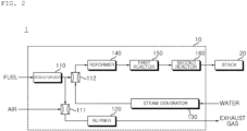
- the fuel cell apparatus 10 may include the desulfurizer 110, the burner 120, the steam generator 130, the reformer 140, the first reactor 150 and/or the second rector 160.
- the fuel cell apparatus 10 may further include at least one mixer, for example, the mixers 111 and 112.
- the desulfurizer 110 may perform desulfurization in which sulfur-combined cooling water is removed from the fuel gas.
- the desulfurizer 110 may include an adsorbent provided therein.
- the sulfur-combined cooling water included in the fuel gas passing through the inside desulfurizer 110 may be adsorbed onto the adsorbent.
- the adsorbent may include a metal oxide, zeolite, activated carbon or the like.
- the desulfurizer 110 may further include a filter configured to remove foreign substances from the fuel gas.
- the steam generator 130 may vaporize the cooling water into steam, and may discharge the steam.
- the steam generator 130 may vaporize the cooling water by absorbing heat from exhaust gas generated by the burner 120, and from the first reactor 150 and/or the second reactor 160.
- the steam generator 130 may be disposed adjacent to the first reactor 150, the second reactor 160 and/or the flow path along which the exhaust gas discharged from the burner 120 flows.
- the first mixer 111 and/or the second mixer 112 may be implemented as an ejector.
- the second mixer 112 may be an ejector which draws in the fuel gas discharged from the desulfurizer 110 using the steam discharged from the steam generator 130.
- the first reactor 150 may reduce carbon monoxide generated by the reforming reaction, among components included gas discharged from the reformer 140.
- carbon monoxide included in the gas discharged from the reformer 140 may react with steam in the first reactor 150, thereby being capable of producing carbon dioxide and hydrogen.
- the inner temperature (for example, 200°C) of the first reactor 150 may be lower than the inner temperature of the reformer 140, and may be higher than room temperature.
- the first reactor 150 may be referred to as a shift reactor.
- the second reactor 160 may reduce remaining carbon monoxide, among components included gas discharged from the first reactor 150.
- preferential oxidation in which carbon monoxide included in the gas discharged from the first reactor 150 reacts with oxygen in the second reactor 160 may occur.
- preferential oxidation requires a large amount of oxygen and thus requires additional supply of air
- hydrogen is diluted with the additionally supplied air, and thus, the concentration of hydrogen supplied to the stacks 20a and 20b is reduced. Therefore, in order to solve such a drawback, selective methanation in which carbon monoxide and hydrogen react with each other may be used.
- the reformed gas moisture remover 61 configured to control the amount of moisture included in the reformed gas may be disposed on the stack gas supply flow path 106. After moisture is removed from the reformed gas introduced into the reformed gas moisture remover 61, the reformed gas may be discharged from the reformed gas moisture remover 61.
- Condensed water generated in the reformed gas moisture remover 61 may be discharged from the reformed gas moisture remover 61, and may flow to a first water recovery flow path 309.
- a first water recovery valve 44 configured to control the flow of the cooling water may be disposed on the first water recovery flow path 309.
- the plurality of stacks 20a and 20b may be connected to each other by a gas connection flow path 107. Unreacted reformed gas discharged from the first stack 20a may flow into the second stack 20b through the gas connection flow path 107.
- the additional moisture remover 62 configured to remove cooling water generated due to condensation of the reformed gas while passing through the first stack 20a may be disposed on the gas connection flow path 107.
- the cooling water generated by the additional moisture remover 62 may be discharged from the additional moisture remover 62, and may flow towards a second water recovery flow path 310.
- a second water recovery valve 45 configured to control the flow of the cooling water may be disposed on the second water recovery flow path 310.
- the second water recovery flow path 310 may be connected to the first water recovery flow path 309.
- Unreacted gas, i.e., AOG gas, discharged from the stacks 20a and 20b may flow along the AOG discharge flow path 108.
- the fifth heat exchanger 22 may be connected to the AOG discharge flow path 108 along which the AOG gas discharged from the stacks 20a and 20b flows.
- the fifth heat exchanger 22 may be connected to a hot water supply flow path 313 along which the cooling water discharged from the heat recovery tank 15 flows.
- the fifth heat exchanger 22 may exchange heat between the AOG gas introduced thereinto through the AOG discharge flow path 108 and the cooling water supplied through the hot water supply flow path 313.
- the hot water pump 48 configured to pump the cooling water stored in the heat recovery tank 15 to the fifth heat exchanger 22 and/or a hot water flowmeter 55 configured to detect the flow rate of the cooling water flowing in the hot water supply flow path 313 may be disposed on the hot water supply flow path 313.
- the fifth heat exchanger 22 may be connected to an AOG supply flow path 109, and may discharge the AOG gas having exchanged heat through the AOG supply flow path 109.
- the AOG gas discharged from the fifth heat exchanger 22 may flow into the fuel processing device 10 through the AOG supply flow path 109.
- the AOG gas supplied to the fuel processing device 10 through the AOG supply flow path 109 may be used as fuel for combustion in the burner 120.
- the AOG discharge flow path 108 and the AOG supply flow path 109 along which the AOG gas discharged from the stacks 20a and 20b flows into the fuel processing device 10 may be referred to as an AOG flow path.
- the AOG discharge flow path 108 may be referred to as the front section of the AOG flow path
- the AOG supply flow path 109 may be referred to as the rear section of the AOG flow path.
- the AOG moisture remover 63 configured to control the amount of moisture included in the AOG gas and an AOG valve 35 configured to control the flow of the AOG supplied to the fuel processing device 10 may be disposed on the AOG supply flow path 109. After moisture is removed from the AOG gas introduced into the AOG moisture remover 63, the AOG gas may be discharged from the AOG moisture remover 63.
- Condensed water generated in the AOG moisture remover 63 may be discharged from the AOG moisture remover 63, and may flow through the third water recovery flow path 311.
- a third water recovery valve 46 configured to control the flow of the cooling water may be disposed on the third water recovery flow path 311.
- the third water recovery flow path 311 may be connected to the first water recovery flow path 309.
- the cooling water discharged from the heat recovery tank 15 by the hot water pump 48 may be introduced into the fifth heat exchanger 22 via the hot water supply flow path 313.
- the cooling water having exchanged heat with the AOG gas in the fifth heat exchanger 22 may be discharged to a first hot water circulation circuit 314.
- a fourth heat exchanger 25 may be connected to the air discharge flow path 212 along which air discharged from the humidifier 23 flows.
- the fourth heat exchanger 25 may be connected to the first hot water circulation circuit 314 in which the cooling water discharged from the fifth heat exchanger 22 flows.
- the fourth heat exchanger 25 may exchange heat between air introduced thereinto through the air discharge flow path 212 and the cooling water introduced into the fourth heat exchanger 25 through the first hot water circulation circuit 314.
- Air having exchanged heat in the fourth heat exchanger 25 may be discharged from the fourth heat exchanger 25 through the exhaust flow path 213.
- the exhaust flow path 213 may be connected to the exhaust gas discharge flow path 210, and the exhaust gas flowing along the exhaust gas discharge flow path 210 and air flowing along the air discharge flow path 212 may be mixed in the exhaust flow path 213.
- the air moisture remover 64 may be disposed on the exhaust flow path 213.
- the air moisture remover 64 may control the amount of moisture included in air discharged to the outside. After moisture is removed from air introduced into the air moisture remover 64, the air may be discharged from the air moisture remover 64.
- Condensed water generated in the air moisture remover 64 may be discharged from the air moisture remover 64, and may flow through a fourth water recovery flow path 312.
- a fourth water recovery valve 47 configured to control the flow of the cooling water may be disposed on the fourth water recovery flow path 312.
- the fourth water recovery flow path 312 may be connected to the water storage flow path 308.
- the cooling water having exchanged heat in the fourth heat exchanger 25 may be discharged from the fourth heat exchanger 25 through a second hot water circulation flow path 315.
- the cooling water discharged from the fourth heat exchanger 35 may be introduced into the cooling water heat exchanger 24 through the second hot water circulation flow path 315.
- the cooling water heat exchanger 24 may exchange heat between water introduced thereinto through the cooling water recovery flow path 307 and the cooling water introduced into the cooling water heat exchanger 24 through the second hot water circulation flow path 315.
- the third heat exchanger 26 may be connected to exhaust gas discharge flow path 210 along which exhaust gas flows.
- the third heat exchanger 26 may be connected to a third hot water circulation flow path 316 along which the cooling water discharged from the cooling water heat exchanger 24 flows.
- the third heat exchanger 26 may exchange heat between the exhaust gas introduced thereinto through the exhaust gas discharge flow path 210 and the cooling water introduced into the third heat exchanger 26 through the third hot water circulation flow path 316.
- the exhaust gas having exchanged heat in the third heat exchanger 26 may be discharged to the exhaust flow path 213, and the exhaust gas flowing along the exhaust flow path 213 may be discharged to the outside.
- the cooling water having exchanged heat in the third heat exchanger 26 may be discharged to the hot water recovery flow path 317, and the cooling water flowing along the hot water recovery flow path 317 may be introduced into the heat recovery tank 15.
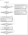
- the burner air blower 71 may draw in external air and discharge the drawn air, the air discharged from the burner air blower 71 may be supplied to the burner 120, and fuel may be supplied to the burner 120, thereby being capable of executing a preheating operation mode in which the burner 120 is operated so as to preheat the reformer 140 (S1) (with reference to FIG. 3 ).
- Air discharged from the burner air blower 71 may be supplied to the three-way valve 500 through the outflow path 201a.
- the controller may control the three-way valve 500 so as to supply the air discharged from the burner air blower 71 to the main air supply flow path 202.
- the air supplied to the three-way valve 500 is not supplied to the vertex tube 502 and is supplied to the burner 120 immediately through the main air supply flow path 202, as the three-way valve 500 is switched towards the main air supply flow path 202, thereby being capable of removing unnecessary pressure loss.
- the burner 120 may heat the reformer 140 through combustion of the received fuel and the air supplied through the main air supply flow path 202. Exhaust gas caused by the combustion may be exhausted to the outside through the exhaust gas discharge flow path 210.
- the controller may determine whether or not a temperature value received from the third temperature sensor 532 configured to sense the inner temperature of the reformer 140 reaches a predetermined reformer temperature value during execution of the preheating operation mode (S2).
- the predetermined reformer temperature value indicates a temperature suitable for reforming reaction between the fuel and steam in the reformer 140 so as to generate reformed gas, and may be a value stored in advance in the memory of the controller.
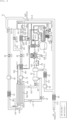
- air discharged from the burner air blower 71 may be supplied to the vertex tube 502.
- the cooling water discharged from the water supply tank 13 may exchange heat with heated air discharged from the vertex tube 502, and may then be supplied to the stacks 20a and 20b.
- the reformed gas generated by the reformer 140 and discharged therefrom may exchange heat with cooled air discharged from the vertex tube 502, and may then be supplied to the burner 120.
- the heated air having exchanged heat and the cooled air having exchanged heat may be supplied to the burner 120, thereby being capable of executing a reforming operation mode (S3) (with reference to FIG. 4 ).
- the fuel and the steam may be supplied to the reformer 140, and reformed gas may be generated through reforming reaction between the fuel and the steam.
- operations of the desulfurizer 120, the mixers 111 and 112 and the steam generator 130 have been descried above and a detailed description thereof will thus be omitted.
- Air discharged from the burner air blower 71 may be supplied to the three-way valve 500 through the outflow path 201a.
- the controller may control the three-way valve 500 so as to supply the air discharged from the burner air blower 71 to the vertex tube 502.
- the air supplied to the three-way valve 500 is supplied to the vertex tube 502 through the vertex air supply flow path 501, as the three-way valve 500 is switched towards the vertex tube 502.
- the vertex tube 502 may convert the received air into heated air and cooled air, and may then discharge the heated air and the cooled air.
- the heated air discharged from the vertex tube 502 may be supplied to the four-way valve 505 through the hot air supply flow path 503.
- the cooled air discharged from the vertex tube 502 may be supplied to the four-way valve 505 through the cold air supply flow path 504.
- the controller may control the four-way valve 505 so as to discharge the heated air discharged from the vertex tube 502 to the first switch flow path 511 and to discharge the cooled air discharged from the vertex tube 502 to the second switch flow path 521 (in the first switch mode).
- the heated air discharged to the first switch flow path 511 may be supplied to the first heat exchanger 510.
- the first heat exchanger 510 may exchange heat between the cooling water discharged from the water supply tank 13 and the heated air.
- the heated air having exchanged heat may be introduced into the main air supply flow path 202 through the first air supply flow path 512, and may be supplied to the burner 120.
- the heated air supplied to the burner 120 may be used in combustion.
- the cooling water stored in the water supply tank 13 may be discharged from the water supply tank 13 by operation of the cooling water pump 43.
- the cooling water discharged from the water supply tank 13 may be preheated through heat exchange with the heated air while passing through the first heat exchanger 510.
- This cooling water may be supplied to the reformed gas heat exchanger 21 through the cooling water flow path 304.
- the cooling water supplied to the reformed gas heat exchanger 21 may be supplied to the stacks 20a and 20b through the stack cooling water supply flow path 305.
- the cooling water supplied to the stacks 20a and 20b may preheat the stacks 20a and 20b, may be discharged to the cooling water recovery flow path 307, and may be returned to the water supply tank 13.
- the preheated cooling water may transfer heat to the stacks 20a and 20b so as to rapidly preheat the stacks 20a and 20b to a temperature suitable for power generation.
- the cooled air discharged to the second switch flow path 521 may be supplied to the second heat exchanger 520.
- the second heat exchanger 520 may exchange heat between the cooled air and the reformed gas discharged from the reformer 140.
- the cooled air having exchanged heat may be introduced into the main air supply flow path 202 through the second air supply flow path 522, and may be supplied to the burner 120.
- the cooled air supplied to the burner 120 may be used in combustion.
- the controller may control the reformed gas valve 33 to be closed and control the reformed gas bypass valve 34 to be opened so as to supply the reformed gas generated by the reformer 140 and discharged therefrom to the burner 120.
- the reformed gas generated by the reformer 140 and discharged therefrom may be cooled through heat exchange with the cooled air while passing through the second heat exchanger 520, and may be supplied to the burner 120 through the reformed gas flow path 104 and the reformed gas bypass flow path 105.
- the reformed gas supplied to the burner 120 may be used in combustion.
- the reformed gas generated by the reformer 140 and discharged therefrom is cooled through heat exchange with the cooled air in the second heat exchanger 520 and is supplied to the burner 120, the reformed gas having an improved density may be supplied to the burner 120 so as to improve combustion efficiency of the burner 120.
- the controller may determine whether or not a concentration value received from the concentration sensor 534 configured to sense the concentration of carbon monoxide included in the reformed gas generated by the reformer 140 reaches a predetermined concentration value during execution of the reforming operation mode (S4).
- the predetermined concentration value indicates a carbon monoxide concentration suitable for the electrochemical reaction in the stacks 20a and 20b, and may be a value stored in advance in the memory of the controller.
- the reformed gas having exchanged heat with the cooled air may exchange heat with the cooling water having exchanged heat with the heated air, and may then be supplied to the stacks 20a and 20b.
- the stack air blower 72 may be operated to supply external air to the stacks 20a and 20b, thereby being capable of executing a power generation operation mode in which electrical energy is generated (S5).
- the positions of the three-way valve 500, the four-way valve 505, the first bypass valve 514 and the second bypass valve 524 and whether or not these valves 500, 505, 514 and 524 are opened or closed in the power generation operation mode may be the same as those in the reforming operation mode.
- the controller may control the reformed gas valve 33 to be opened and control the reformed gas bypass valve 34 to be closed so as to supply the reformed gas generated by the reformer 140 and discharged therefrom to the stacks 20a and 20b.
- the reformed gas generated by the reformer 140 and discharged therefrom may be cooled through heat exchange with the cooled air while passing through the second heat exchanger 520, and may then be supplied to the reformed gas heat exchanger 21 through the reformed gas flow path 104.
- the cooling water stored in the water supply tank 13 may be discharged from the water supply tank 13 by operation of the cooling water pump 43.
- the cooling water discharged from the water supply tank 13 may be preheated through heat exchange with the heated air while passing through the first heat exchanger 510, and may then be supplied to the reformed gas heat exchanger 21 through the cooling water flow path 304.
- the reformed gas heat exchanger 21 may exchange heat between the supplied cooling water and the reformed gas.
- the reformed gas having exchanged heat with the cooling water may be supplied to the stacks 20a and 20b through the stack gas supply flow path 106.
- the cooling water having exchanged heat with the reformed gas may be supplied to the stacks 20a and 20b through the stack cooling water supply flow path 305.
- the preheated cooling water may transfer heat to the stacks 20a and 20b so as to more rapidly preheat the stacks 20a and 20b to a temperature suitable for power generation.
- the reformed gas cooled while passing through the second heat exchanger 520 is additionally cooled by the cooling water in the reformed gas heat exchanger 21 and is then supplied to the stacks 20a and 20b, the reformed gas having an improved density may be supplied to the stacks 20a and 20b so as to greatly improve power generation efficiency of the stacks 20a and 20b.
- the controller may operate the stack air blower 72 and open the stack-in valve 36 so as to supply external air to the stacks 20a and 20b.
- Air introduced into the stack air blower 72 through the second external air inflow path 203 may be supplied to the humidifier 23 through the stack-side air inflow path 204.
- Air charged with moisture in the humidifier 23 may be supplied to the stacks 20a and 20b through the stack-side air supply flow path 205.
- the air flowmeter 53 disposed on the stack-side air inflow path 204 may sense the flow rate of air supplied to the stacks 20a and 20b.
- the controller may open the stack-out valve 37 so as to exhaust air from the stacks 20a and 20b to the outside. Air supplied to the stacks 20a and 20b may cause an electrochemical reaction with the reformed gas, and may then be discharged to the humidifier 23 through the stack-side air discharge flow path 211. Moisture included in the discharged air may be absorbed by the humidifier 23.
- the air charged with moisture may be supplied to the fourth heat exchanger 25 through the air discharge flow path 212.
- the air having passed through the fourth heat exchanger 25 may be supplied to the exhaust gas discharge flow path 210 through the exhaust flow path 213.
- the air supplied to the exhaust gas discharge flow path 210 together with exhaust gas may be supplied to the third heat exchanger 26.
- the air having passed through the third heat exchanger 26 together with the exhaust gas may be exhausted to the outside through the exhaust flow path 213.
- the stacks 20a and 20b may generate electrical energy through the electrochemical reaction between the supplied reformed gas and air.
- the electrochemical reaction results in generation of heat and moisture, and such heat and moisture generated as a result of the electrochemical reaction may be discharged through the cooling water supplied to the stacks 20a and 20b, and generated steam together with air discharged from the stacks 20 and 20b may be exhausted.
- the controller may determine whether or not a temperature value received from the first temperature sensor 530 configured to sense the temperature Tw of the cooling water discharged from the stacks 20a and 20b is equal to or higher than a predetermined cooling water temperature value T1 during execution of the power generation operation mode (S6) .
- the predetermined cooling water temperature value T1 indicates a temperature effective in causing the electrochemical reaction between the reformed gas and air in the stacks 20a and 20b, and may be a value stored in advance in the memory of the controller.
- the controller may control the cooling water discharged from the vertex tube 502 to be supplied to the burner 120 without heat exchange with the reformed water generated by the reformer 140 and discharged therefrom (S61).
- Such an operation mode of the fuel cell apparatus 1 may be referred to as an additional cooling water preheating mode (with reference to FIG. 5 ).
- the controller may control the three-way valve 500 to supply air discharged from the burner air blower 71 to the vertex tube 502. For example, the controller may switch the three-way valve 500 towards the vertex tube 502, or may maintain the position of the three-way valve 500 switched towards the vertex tube 502. Air supplied to the three-way valve 500 may be supplied to the vertex tube 502 through the vertex air supply flow path 501.
- the controller may control the four-way valve 505 to discharge the heated air discharged from the vertex tube 502 to the first switch flow path 511 and to discharge the cooled air to the second switch flow path 521 (in the above-described first switch mode). For example, the controller may switch the four-way valve 505 to the first switch mode, or maintain the position of the four-way valve 505 switched to the first switch mode.
- the controller may control the first bypass valve 514 to be closed and the second bypass valve 524 to be opened. For example, the controller may maintain the closed position of the first bypass valve 514. For example, the controller may open the second bypass valve 524, or may maintain the open position of the second bypass valve 524.
- the heated air discharged to the first switch flow path 511 does not flow to the first bypass flow path 513 due to the closed first bypass valve 514, and may be supplied to the first heat exchanger 510.
- the first heat exchanger 510 may exchange heat between the cooling water discharged from the water supply tank 13 and the heated air.
- the heated air having exchanged heat may be introduced into the main air supply flow path 202 through the first air supply flow path 512, and may be supplied to the burner 120.
- the heated air supplied to the burner 120 may be used in combustion.
- the cooled air discharged to the second switch flow path 521 is not supplied to the second heat exchanger 520 due to the closed first bypass valve 514, may flow to the second bypass flow path 523, and may then be supplied to the second air supply flow path 522.
- the cooled air supplied to the second air supply flow path 522 may be introduced into the main air supply flow path 202, and may be supplied to the burner 120.
- the cooled air supplied to the burner 120 may be used in combustion.
- the heated air to be supplied to the burner 120 exchanges heat with the cooling water in the first heat exchanger 510 and is then supplied to the burner 120 and the cooled air to be supplied to the burner 120 bypasses the second heat exchanger 520 and is supplied to the burner 120 while maintaining a low temperature, the temperature of air supplied to the burner 120 is lowered and thus the density of air is improved, thereby being capable of improving combustion efficiency of the burner 120.
- the cooling water stored in the water supply tank 13 may be discharged from the water supply tank 13 by operation of the cooling water pump 43.
- the cooling water discharged from the water supply tank 13 may be preheated through heat exchange with the heated air while passing through the first heat exchanger 510, and may then be supplied to the reformed gas heat exchanger 21 through the cooling water flow path 304.
- the reformed gas generated by the reformer 140 and discharged therefrom may be supplied to the reformed gas heat exchanger 21 through the reformed gas flow path 104.
- the reformed gas may pass through the second heat exchanger 520 while maintaining the high temperature state without losing heat to the cooled air although the reformed gas passes through the second heat exchanger 520.
- the reformed gas heat exchanger 21 may exchange heat between the supplied cooling water and the reformed gas.
- the reformed gas supplied to the reformed gas heat exchanger 21 without losing heat to the cooled air in the second heat exchanger 520 may transfer heat to the cooling water so as to additionally preheat the cooling water, and may then be supplied to the stacks 20a and 20b through the stack gas supply flow path 106.
- the cooling water having passed through the reformed gas heat exchanger 21 may be supplied to the stacks 20a and 20b through the stack cooling water supply flow path 305.
- the cooling water supplied to the stacks 20a and 20b may preheat the stacks 20a and 20b, may be discharged from the stacks 20a and 20b, and may then be returned to the water supply tank 13.
- the cooling water bypasses the second heat exchanger 520 so that the reformed gas does not lose heat to the cooled air in the second heat exchanger 520.
- the reformed gas may be supplied to the reformed gas heat exchanger 21 while maintaining the high temperature state, and thus exchanges heat with the cooling water. Therefore, the cooling water passing through the reformed gas heat exchanger 21 may be effectively preheated so as to more rapidly preheat the stacks 20a and 20b to the temperature suitable for power generation.
- the controller may determine whether or not a difference between the received temperature value Tw and the predetermined cooling water temperature value T1 is less than a predetermined difference value D (S7).
- the predetermined difference value D is a value defining the width of a section from a temperature T1 to a temperature T1+D, which is effective in causing the electrochemical reaction between the reformed gas and air in the stacks 20a and 20b, and may be a value stored in advance in the memory of the controller.
- the controller may control the cooled air discharged from the vertex tube 502 to exchange heat with the cooling water discharged from the water supply tank 13 and then to be supplied to the burner 120, and may control the heated air discharged from the vertex tube 502 to be supplied to the burner 120 without exchanging heat with the reformed gas generated by the reformer 140 and discharged therefrom (S71).
- Such an operation mode of the fuel cell apparatus 1 may be referred to as a cooling water overheating control mode (with reference to FIG. 6 ).
- the controller may control the three-way valve 500 to supply air discharged from the burner air blower 71 to the vertex tube 502. For example, the controller may switch the three-way valve 500 towards the vertex tube 502, or may maintain the position of the three-way valve 500 switched towards the vertex tube 502. Air supplied to the three-way valve 500 may be supplied to the vertex tube 502 through the vertex air supply flow path 501.
- the controller may control the four-way valve 505 to discharge the heated air discharged from the vertex tube 502 to the second switch flow path 521 and to discharge the cooled air to the first switch flow path 511 (in the above-described second switch mode). For example, the controller may switch the four-way valve 505 to the second switch mode, or maintain the position of the four-way valve 505 switched to the second switch mode.
- the controller may control the first bypass valve 514 to be closed and the second bypass valve 524 to be opened. For example, the controller may maintain the closed position of the first bypass valve 514. For example, the controller may open the second bypass valve 524, or may maintain the open position of the second bypass valve 524.
- the cooled air discharged to the first switch flow path 511 does not flow to the first bypass flow path 513 due to the closed first bypass valve 514, and may be supplied to the first heat exchanger 510.
- the first heat exchanger 510 may exchange heat between the cooling water discharged from the water supply tank 13 and the cooled air.
- the cooled air having exchanged heat may be introduced into the main air supply flow path 202 through the first air supply flow path 512, and may be supplied to the burner 120.
- the cooled air supplied to the burner 120 may be used in combustion.
- the heated air discharged to the second switch flow path 521 is not supplied to the second heat exchanger 520 due to the closed first bypass valve 514, may flow to the second bypass flow path 523, and may then be supplied to the second air supply flow path 522.
- the heated air supplied to the second air supply flow path 522 may be introduced into the main air supply flow path 202, and may be supplied to the burner 120.
- the heated air supplied to the burner 120 may be used in combustion.
- the cooling water stored in the water supply tank 13 may be discharged from the water supply tank 13 by operation of the cooling water pump 43.
- the cooling water discharged from the water supply tank 13 may be cooled through heat exchange with the cooled air while passing through the first heat exchanger 510, and may then be supplied to the reformed gas heat exchanger 21 through the cooling water flow path 304.
- the reformed gas generated by the reformer 140 and discharged therefrom may be supplied to the reformed gas heat exchanger 21 through the reformed gas flow path 104.
- the reformed gas may pass through the second heat exchanger 520 without exchanging heat with the heated air although the reformed gas passes through the second heat exchanger 520.
- the reformed gas heat exchanger 21 may exchange heat between the supplied cooling water and the reformed gas.
- the reformed gas supplied to the reformed gas heat exchanger 21 may transfer heat to the cooling water so as to preheat the cooling water, and may then be supplied to the stacks 20a and 20b through the stack gas supply flow path 106.
- the cooling water having passed through the reformed gas heat exchanger 21 may be supplied to the stacks 20a and 20b through the stack cooling water supply flow path 305.
- the cooling water supplied to the stacks 20a and 20b may absorb heat from the stacks 20a and 20b, may be discharged to the cooling water recovery flow path 307, and may then be returned to the water supply tank 13.
- the cooling water since the cooling water is cooled through heat exchange with the cooled air in the first heat exchanger 510 and is then supplied to the stacks 20a and 20b, the cooling water may effectively absorb heat generated by the electromechanical reaction in the stacks 20a and 20b. Thus, the cooling water may maintain the proper temperature without overheating.
- the controller may control the heated air discharged from the vertex tube 502 to be supplied to the burner 120 without exchanging heat with the cooling water discharged from the water supply tank 13, and may control the cooled air discharged from the vertex tube 502 to exchange heat with the reformed gas generated by the reformer 140 and discharged therefrom and then to be supplied to the burner 120 (S8).
- Such an operation mode of the fuel cell apparatus 1 may be referred to as a cooling water temperature stabilization and reformed gas cooling mode (with reference to FIG. 7 ).
- the controller may control the three-way valve 500 to supply air discharged from the burner air blower 71 to the vertex tube 502. For example, the controller may switch the three-way valve 500 towards the vertex tube 502, or may maintain the position of the three-way valve 500 switched towards the vertex tube 502. Air supplied to the three-way valve 500 may be supplied to the vertex tube 502 through the vertex air supply flow path 501.
- the controller may control the four-way valve 505 to discharge the heated air discharged from the vertex tube 502 to the first switch flow path 511 and to discharge the cooled air to the second switch flow path 521 (in the above-described first switch mode). For example, the controller may switch the four-way valve 505 to the first switch mode, or maintain the position of the four-way valve 505 switched to the first switch mode.
- the controller may control the first bypass valve 514 to be opened and the second bypass valve 524 to be closed.
- the controller may open the closed first bypass valve 514.
- the controller may close the second bypass valve 524, or may maintain the closed position of the second bypass valve 524.
- the heated air discharged to the first switch flow path 511 does not flow to the first heat exchanger 510 due to the open first bypass valve 514, and may be supplied to the first air supply flow path 512 through the first bypass flow path 513.
- the heated air supplied to the first air supply flow path 512 may be introduced into the main air supply flow path 202, and may be supplied to the burner 120.
- the heated air supplied to the burner 120 may be used in combustion.
- the cooled air discharged to the second switch flow path 521 does not flow to the second bypass flow path 523 due to the closed second bypass valve 524, and may be supplied to the second heat exchanger 520.
- the second heat exchanger 520 may exchange heat between the reformed gas discharged from the reformer 140 and the cooled air.
- the cooled air having exchanged heat may be introduced into the main air supply flow path 202 through the second air supply flow path 522, and may be supplied to the burner 120.
- the cooled air supplied to the burner 120 may be used in combustion.
- the cooling water stored in the water supply tank 13 may be discharged from the water supply tank 13 by operation of the cooling water pump 43.
- the cooling water may pass through the first heat exchanger 510 without exchanging heat with the heated air although the cooling water passes through the first heat exchanger 510.
- the cooling water having passed through the first heat exchanger 510 may be supplied to the reformed gas heat exchanger 21 through the cooling water flow path 304.
- the reformed gas generated by the reformer 140 and discharged therefrom may be cooled through heat exchange with the cooled air while passing through the second heat exchanger 520, and may then be supplied to the reformed gas heat exchanger 21 through the reformed gas flow path 104.
- the reformed gas heat exchanger 21 may exchange heat between the supplied cooling water and the reformed gas.
- the reformed gas supplied to the reformed gas heat exchanger 21 may transfer heat to the cooling water so as to preheat the cooling water, and may then be supplied to the stacks 20a and 20b through the stack gas supply flow path 106.
- the cooling water having passed through the reformed gas heat exchanger 21 may be supplied to the stacks 20a and 20b through the stack cooling water supply flow path 305.
- the cooling water supplied to the stacks 20a and 20b may absorb heat from the stacks 20a and 20b, may be discharged to the cooling water recovery flow path 307, and may then be returned to the water supply tank 13.
- the reformed gas since the reformed gas is primarily cooled through heat exchange with the cooled air in the second heat exchanger 520, is additionally cooled through heat exchange with the cooling water in the reformed gas heat exchanger 21, and is then supplied to the stacks 20a and 20b, the reformed gas having an improved density may be supplied to the stacks 20a and 20b so as to greatly improve power generation efficiency of the stacks 20a and 20b.
- the cooling water passing through the first heat exchanger 510 does not exchange heat with the heated air, and thus, the temperature of the cooling water may be maintained.
- the controller may determine whether or not a temperature value received from the second temperature sensor 531 configured to sense the temperature Tg of the reformed gas supplied to the stacks 20a and 20b is equal to or lower than a predetermined reformed gas temperature value T2 during execution of the cooling water temperature stabilization and reformed gas cooling mode (S9).
- the predetermined reformed gas temperature value T2 indicates the maximum temperature out of the temperature values of the reformed gas configured to form a reformed gas density effective in causing the electrochemical reaction in the stacks 20a and 20b, and may be a value stored in advance in the memory of the controller.
- the controller may control air discharged from the burner air blower 71 to be supplied to the burner 120 (S10) .
- Such an operation mode of the fuel cell apparatus 1 may be referred to as a normal operation mode (with reference to FIG. 8 ).
- the controller may control the three-way valve 500 to supply air discharged from the burner air blower 71 to the burner 120.
- the controller may switch the three-way valve 500 towards the burner 120. Air supplied to the three-way valve 500 may be supplied to the burner 120 through the main air supply flow path 202.
- the controller may control both the first bypass valve 514 and the second bypass valve 524 to be closed. For example, the controller may close the open first bypass valve 514. For example, the controller may maintain the closed position of the second bypass valve 524.
- the cooling water stored in the water supply tank 13 may be discharged from the water supply tank 13 by operation of the cooling water pump 43.
- the cooling water may pass through the first heat exchanger 510 without separate heat exchange.
- the cooling water having passed through the first heat exchanger 510 may be supplied to the reformed gas heat exchanger 21 through the cooling water flow path 304.
- the reformed gas generated by the reformer 140 and discharged therefrom may pass through the second heat exchanger 520 without separate heat exchange.
- the reformed gas having passed through the second heat exchanger 520 may be supplied to the reformed gas heat exchanger 21 through the reformed gas flow path 104.
- the reformed gas heat exchanger 21 may exchange heat between the supplied cooling water and the reformed gas.
- the reformed gas supplied to the reformed gas heat exchanger 21 may transfer heat to the cooling water so as to preheat the cooling water, and may then be supplied to the stacks 20a and 20b through the stack gas supply flow path 106.
- the cooling water having passed through the reformed gas heat exchanger 21 may be supplied to the stacks 20a and 20b through the stack cooling water supply flow path 305.
- the cooling water supplied to the stacks 20a and 20b may absorb heat from the stacks 20a and 20b, may be discharged to the cooling water recovery flow path 307, and may then be returned to the water supply tank 13.
- the controller may confirm a time Tn at which the fuel cell apparatus 1 enters the normal operation mode, and store the confirmed time in the memory.
- the controller may confirm a present time Tn+1 during execution of the normal operation mode, and may calculate an elapsed time (Tn+1)-Tn after entering the normal operation mode.
- the controller may determine whether or not the elapsed time (Tn+1)-Tn after entering the normal operation mode is longer than a control cycle time C (S11).
- the fuel cell apparatus 1 may return to Operation S6 so as to start control of the temperatures of the cooling water and the reformed gas.
- control cycle time C is a cycle time configured to control the temperatures of the cooling water and the reformed gas, and may be a value stored in advance in the memory of the controller.
- this embodiment describes Operations S1 to S11 in order of time, this is only one embodiment for assisting in understanding of the present disclosure, and the present disclosure is not limited to this order in performance of Operations S1 to S11.
- a three-way valve is controlled to supply air blown from a burner air blower to a burner rather than to a vertex tube, thereby being capable of removing unnecessary pressure loss from air supplied to the burner.
- the three-way valve is controlled to supply air blown from the burner air blower to the vertex tube
- a four-way valve is controlled to supply heated air discharged from the vertex tube to a first heat exchanger and cooled air discharged from the vertex tube to a second heat exchanger
- first and second bypass valves are closed, so as to preheat cooling water through heat exchange with the heated air in the first heat exchanger and then to supply the cooling water to stacks, thereby allowing the preheated cooling water to transfer heat to the stacks and thus being capable of rapidly preheating the stacks to a temperature suitable for power generation.
- the reformed gas generated by the reformer and discharged therefrom exchanges heat with the cooled air in the second heat exchanger and is then supplied to the burner, so as to supply the reforming gas having an improved density to the burner, thereby being capable of improving combustion efficiency of the burner.
- the cooling water preheated by the heated air while passing through the first heat exchanger is additionally preheated by the reformed gas in a reformed gas heat exchanger and is then supplied to the stacks, so as to enable the preheated cooling water to transfer heat to the stacks, thereby being capable of more rapidly preheating the stacks to the temperature suitable for power generation.
- the reformed gas cooled by the cooled air while passing through the second heat exchanger is additionally cooled by the cooling water in the reformed gas heat exchanger and is then supplied to the burner, so as to supply the reforming gas having an improved density to the stacks, thereby being capable of improving power generation efficiency of the stacks.
- the first bypass valve is controlled to be closed and the second bypass valve is controlled to be opened, and thus, the heated air supplied to the burner is cooled through heat exchange with the cooling water in the first heat exchanger and is then supplied to the burner, and the cooled air supplied to the burner bypasses the second heat exchanger and is supplied to the burner while maintaining a low temperature, thereby improving combustion efficiency of the burner through supply of air having an improved density to the burner.
- the reformed gas discharged from the reformer when supplied to the reformed gas heat exchanger through the second heat exchanger, the cooled air bypasses the second heat exchanger, the reformed gas does not lose heat to the cooled air in the second heat exchanger and is supplied to the reformed gas heat exchanger while maintaining a high temperature so as to exchange heat with the cooled air, and thus, the cooling water passing through the reformed gas heat exchanger is effectively preheated, thereby being capable of more rapidly preheating the stacks to the temperature suitable for power generation.
- the four-way valve is controlled to supply the heated air discharged from the vertex tube to the second heat exchanger and to supply the cooled air to be supplied to the first heat exchanger, and thus allows the cooling water to be cooled through heat exchange in the first heat exchanger and then to be supplied to the stacks, thereby enabling the cooling water to effectively absorb heat generated due to an electrochemical reaction in the stacks and to maintain a proper temperature without overheating.
- the reformed gas is primarily cooled through heat exchange with the cooled air in the second heat exchanger, is additionally cooled through heat exchange with the cooling water in the reformed gas heat exchanger, and is then supplied to the stacks, so as to supply the reformed gas having an improved density to the stacks, thereby being capable of greatly improving power generation efficiency of the stacks.
- the four-way valve is controlled to supply the heated air discharged from the vertex tube to the first heat exchanger and to supply the cooled air to be supplied to the second heat exchanger
- the first bypass valve is controlled to be opened
- the second bypass valve is controlled to be closed, so as to prevent the heated air from being supplied to the first heat exchanger and thus to prevent the cooling water passing through the first heat exchanger from exchanging heat with the heated air, thereby being capable of maintaining the temperature of the cooling water.
- the three-way valve is switched towards the burner so as to prevent unnecessary heat exchange between the cooling water and the reformed gas in the first and second heat exchanger, thereby being capable of maintaining the temperatures of the cooling water and the reformed gas and thus maintaining high power generation efficiency of the stacks.
Landscapes
- Chemical & Material Sciences (AREA)
- Engineering & Computer Science (AREA)
- Life Sciences & Earth Sciences (AREA)
- Manufacturing & Machinery (AREA)
- Sustainable Development (AREA)
- Sustainable Energy (AREA)
- Chemical Kinetics & Catalysis (AREA)
- Electrochemistry (AREA)
- General Chemical & Material Sciences (AREA)
- Combustion & Propulsion (AREA)
- Fuel Cell (AREA)
Abstract
Disclosed are a fuel cell apparatus and a method for controlling the same. The fuel cell apparatus includes a stack, a reformer configured to generate reformed gas, a burner, a water supply tank configured to store cooling water, a burner air blower configured to draw in external air and then to blow the air, a vertex tube configured to convert the air into heated air and cooled air, a three-way valve configured to supply the air from the burner air blower selectively to the vertex tube or the burner, a first heat exchanger configured to exchange heat between the air discharged from the vertex tube and the cooling water, a second heat exchanger configured to exchange heat between the air discharged from the vertex tube and the reformed gas, and a four-way valve configured to supply the heated air and the cooled air to the first and second heat exchangers.
Description
- The present disclosure relates to a fuel cell apparatus and a method for controlling the same, and more particularly, to a fuel cell apparatus which may control the temperatures of cooling water and reformed gas using a vertex tube.
- A fuel cell apparatus is a power generation apparatus which generates electrical energy through an electrochemical reaction between hydrogen included in a hydrocarbon-based substance, for example, methanol, ethanol, natural gas or the like, and oxygen.
- The conventional fuel cell apparatus includes, in a similar manner to a fuel cell system disclosed in Related Art Document 1 (
Korean Patent Unexamined Publication No. 10-2012-0071288 - Since oxygen is essentially used in combustion of fuel gas in a burner of the fuel processor or power generation in the stack, in general, the fuel cell apparatus includes a blower configured to blow external air to the fuel processor or the stack, in a similar manner to a fuel cell system disclosed in Related Art Document 2 (
Korean Patent Registration No. 10-1951439 - The conventional fuel cell apparatus may be first operated in a preheating mode in which a reformer configured to generate reformed gas necessary to generate electricity in the stack using fuel gas is preheated to a temperature suitable for reforming by the burner, may be operated in a reforming mode in which reforming is repeated while recirculating the reformed gas generated by the reformer to the burner until hydrogen, carbon monoxide, etc. in the generated reformed gas reach concentrations suitable for power generation in the stack, when the reformer reaches the above temperature condition, and may be operated in a power generation mode in which the reformed gas and external air are supplied to the stack so as to produce electrical energy through the electrochemical reaction, when the reformed gas reaches the above concentration condition.
- The stack generally exhibits the maximum power generation efficiency at a temperature of about 75°C, the stack starts to be preheated due to supply of the high-temperature reformed gas and the cooling water heated through heat exchange with the reformed gas only when the conventional fuel cell apparatus enters power generation operation, and thus, the temperature of the stack is low and thus power generation efficiency is low at the initial stage of the power generation operation of the fuel cell apparatus.
- The stack generates heat depending on the power generation operation of the fuel cell apparatus, and such heat enables the stack to reach a temperature suitable for power generation at the initial stage of the power generation operation of the fuel cell apparatus, but needs to be radiated so as to prevent the stack from overheating after the stack reaches a target temperature.
- In the conventional fuel cell apparatus, in a situation in which the power generation mode is maintained for a designated time and the stack reaches the target temperature and thus requires radiation of heat generated due to operation of the fuel cell apparatus, hot water in a water supply tank configured to store recovered heat by circulating the cooling water depending on operation of the fuel cell apparatus is discharged to the outside and then cold water from an external water supply source is supplied to the water supply tank, and thus, it is difficult to achieve delicate heat management of the fuel cell apparatus and additional operation costs due to water supply are incurred.
- (Patent Document 1)
KR 10-2012-0071288 A - (Patent Document 2)
KR 10-1951439 B - It is an object of the present disclosure to provide a fuel cell apparatus capable of shortening a time taken to preheat a stack to a temperature suitable for power generation so as to improve power generation efficiency.
- It is another object of the present disclosure to provide a fuel cell apparatus capable of simply and effectively radiating waste heat generated by a stack so as to maintain the optimum temperature.
- It is still another object of the present disclosure to provide a fuel cell apparatus capable of improving the density of reformed gas supplied to a burner or a stack so as to improve combustion efficiency of the burner or power generation efficiency of the stack.
- It is still another object of the present disclosure to provide a fuel cell apparatus capable of improving the density of air supplied to a burner so as to improve combustion efficiency of the burner.
- It is still another object of the present disclosure to provide a fuel cell apparatus capable of delicately managing the temperature of cooling water supplied to a stack so as to reach the optimum temperature.
- It is still another object of the present disclosure to provide a fuel cell apparatus capable of delicately managing the temperature of reformed gas supplied to a burner or a stack so as to reach the optimum temperature.
- The present disclosure is not limited to the above-described objects, and it is to be understood that other objects which are not described herein will be apparent to those skilled in the art from the following description.
- In order to accomplish the above and other objects, a fuel cell apparatus according to one aspect of the present disclosure includes a stack, a reformer configured to generate reformed gas and to supply the reformed gas to the stack, a burner configured to heat the reformer, a water supply tank configured to store cooling water supplied to the stack, a burner air blower configured to draw in external air and then to blow the air, a vertex tube configured to convert the air into heated air and cooled air, and a three-way valve configured to supply the air blown from the burner air blower selectively to the vertex tube or the burner.
- The fuel cell apparatus may further include a first heat exchanger configured to exchange heat between the air discharged from the vertex tube and the cooling water supplied from the water supply tank to the stack and then to supply the air to the burner, a second heat exchanger configured to exchange heat between the air discharged from the vertex tube and the reformed gas discharged from the reformer and then to supply the air to the burner, and a four-way valve configured to supply the heated air and the cooled air discharged from the vertex tube to different ones out of the first heat exchanger and the second exchanger. In the other words, the four-way valve may be configured to discharge the heated air to one of a first switch flow path and a second switch flow path, and to discharge the cooled air to the other one of the first switch flow path and the second switch flow path;
- The fuel cell apparatus may further include a reformed gas bypass flow path configured to allow the reformed gas discharged from the reformer and having passed through the second heat exchanger to be supplied to the burner, and a reformed gas bypass valve disposed on the reformed gas bypass flow path so as to be opened and closed.
- Therefore, as the cooling water discharged from the water supply tank is preheated through heat exchange with the heated air in the first heat exchanger and is then supplied to the stack, the preheated cooling water may transfer heat to the stack, and may thus rapidly preheat the stack to a temperature suitable for power generation.
- Further, as the reformed gas generated by the reformer and discharged therefrom is cooled through heat exchange with the cooled air in the second heat exchanger and is then supplied to the burner or the stack, the reformed gas having an improved density may be supplied to the burner or the stack, and may thus improve combustion efficiency of the burner or power generation efficiency of the stack.
- In addition, the three-way valve may be switched so as to prevent unnecessary heat exchange between the cooling water and the reformed gas reaching temperatures suitable for power generation in the first and second heat exchanger, and thus, air blown from the burner air blower may be supplied to the burner rather than the vertex tube, the optimum temperatures of the cooling water and the reformed gas may be maintained, and high power generation efficiency of the stack may be maintained.
- The fuel cell apparatus may further include a reformed gas heat exchanger configured to exchange heat between the cooling water having exchanged heat while passing through the first heat exchanger and the reformed gas having exchanged heat while passing through the second heat exchanger and then to supply the cooling water and the reformed gas to the stack, a first bypass flow path configured to allow the air supplied from the vertex tube to the first heat exchanger to bypass the first heat exchanger, a first bypass valve disposed on the first bypass flow path and configured to be opened and closed, a second bypass flow path configured to allow the air supplied from the vertex tube to the second heat exchanger to bypass the second heat exchanger, and a second bypass valve disposed on the second bypass flow path and configured to be opened and closed.
- Therefore, as the cooled air bypasses the second heat exchanger so that the reformed gas does not lose heat to the cooled air in the second heat exchanger while passing through the second heat exchanger, the reformed gas may be supplied to the reformed gas heat exchanger without heat loss so as to exchange heat with the cooling water, and may thus effectively preheat the cooling water passing through the reformed gas heat exchanger.
- Further, the first bypass valve may be opened so as not to supply the heated air to the first heat exchanger or the four-way valve may be switched so as not to supply the cooled air to the first heat exchanger, and may prevent the cooling water passing through the first heat exchanger from being preheated or allow the cooling water to be cooled, and therefore, the cooling water may maintain a proper temperature without overheating.
- Other aspects of the present disclosure will become apparent from the detailed description of the following aspects in conjunction with the accompanying drawings.
- The above and other objects, features and other advantages of the present disclosure will be more clearly understood from the following detailed description taken in conjunction with the accompanying drawings, in which:
-
FIG. 1 is a diagram of a fuel cell apparatus according to the present disclosure; -
FIG. 2 is a schematic block diagram showing the configuration of the fuel cell apparatus according to the present disclosure; -
FIG. 3 is a diagram illustrating the preheating operation mode of the fuel cell apparatus according to the present disclosure; -
FIG. 4 is a diagram illustrating the reforming operation mode of the fuel cell apparatus according to the present disclosure; -
FIG. 5 is a diagram illustrating the additional cooling water preheating mode of the fuel cell apparatus according to the present disclosure; -
FIG. 6 is a diagram illustrating the cooling water overheating control mode of the fuel cell apparatus according to the present disclosure; -
FIG. 7 is a diagram illustrating the cooling water temperature stabilization and reformed gas cooling mode of the fuel cell apparatus according to the present disclosure; -
FIG. 8 is a diagram illustrating the normal operation mode of the fuel cell apparatus according to the present disclosure; and -
FIGS. 9 and10 are flowcharts showing a method for controlling the fuel cell apparatus according to the present disclosure. - Advantages and features of the present disclosure and methods for achieving the same will become apparent from the descriptions of aspects herein below with reference to the accompanying drawings. However, the present disclosure is not limited to the aspects disclosed herein but may be implemented in various different forms. The aspects are provided to make the description of the present disclosure thorough and to fully convey the scope of the present disclosure to those skilled in the art. It is to be noted that the scope of the present disclosure is defined only by the claims. The use of the same reference numerals or symbols in the following description of the present disclosure indicates same elements.
- The terminology used herein is for the purpose of describing particular embodiments only and is not intended to be limiting. As used herein, singular forms may be intended to include plural forms as well, unless the context clearly indicates otherwise. The terms "comprising," "including," and/or "having" are inclusive and therefore specify the presence of stated features, integers, steps, operations, elements, components, and/or combinations thereof, but do not preclude the presence or addition of one or more other features, integers, steps, operations, elements, components, and/or combinations thereof.
- Unless defined otherwise, all terms (including technical and scientific terms) used in the following description have the same meanings as those of terms generally understood by those skilled in the art. Terms defined in generally used dictionaries will be interpreted as having meanings coinciding with contextual meanings in the related technology, and are not to be interpreted as having ideal or excessively formal meanings unless defined clearly in the description.
- Hereinafter, respective parts of a
fuel cell apparatus 1 will be described with reference toFIG. 1 . - The
fuel cell apparatus 1 may include a fuel processor I, a power generator II, a water circulator III and/or a heat recoverer IV. Thefuel cell apparatus 1 may further include a power converter (not shown) including a power conversion device configured to convert DC power produced by the power generator II into AC power. - The fuel processor I may include a
fuel processing device 10, afuel valve 30 configured to control the flow of fuel gas supplied to thefuel processing device 10, and aburner air blower 71 configured to blow air to thefuel processing device 10. - The power generator II may include
stacks gas heat exchanger 21 configured to exchange heat with reformed gas discharged from thefuel processing device 10, afifth heat exchanger 22 configured to exchange heat with unreacted gas discharged from thestacks humidifier 23 configured to supply moisture to air supplied to thestacks stack air blower 72 configured to blow air to thestacks stacks fuel cell apparatus 1 includes twostacks - The water circulator III may include a
water supply tank 13 configured to store water produced by thefuel cell apparatus 1, awater pump 38 configured to pump water to thefuel processing device 10, awater supply valve 39 configured to control the flow of water supplied to thefuel processing device 10, and acooling water pump 43 configured to pump water to the reformedgas heat exchanger 21. - The heat recoverer IV may include a
heat recovery tank 15 configured to store water used in heat exchange, and ahot water pump 48 configured to pump water stored in theheat recovery tank 15 to the outside of theheat recovery tank 15. - Hereinafter, in order to assist in understanding of the technical idea of the present disclosure, among the respective parts and the elements of the respective parts, specific elements will be described first regardless of the sequence of operation of the respective parts or the elements of the respective parts.
- Referring to
FIGS. 1 to 3 , thefuel cell apparatus 1 according to the present disclosure includes thestacks reformer 140 configured to generate reformed gas and then to supply the reformed gas to thestacks burner 120 configured to heat thereformer 140, thewater supply tank 13 configured to store the cooling water supplied to thestacks burner air blower 71 configured to draw in external air and then to supply the air to theburner 120, avortex tube 502 configured to convert air into heated air and cooled air, and a three-way valve 500 configured to supply the air blown from theburner air blower 71 selectively to thevortex tube 502 or theburner 120. - Further, the
fuel cell apparatus 1 includes afirst heat exchanger 510 configured to exchange heat between the air discharged from thevertex tube 502 and the cooling water supplied from thewater supply tank 13 to thestacks burner 120, asecond heat exchanger 520 configured to exchange heat between the air discharged from thevertex tube 502 and the reformed gas discharged from thereformer 140 and then to supply the air to theburner 120, and a four-way valve 505 configured to supply the heated air and the cooled air discharged from thevertex tube 502 to different ones out of thefirst heat exchanger 510 and thesecond heat exchanger 520. - The
stacks stacks fuel processing device 10 and oxygen supplied from external air. - The
stacks - The
reformer 140 may generate reformed gas by reforming fuel gas, and may supply the reformed gas to thestacks - For example, the
reformer 140 may perform a reforming process for generating hydrogen gas from fuel gas, from which sulfur compounds are removed, using a catalyst. Here, the catalyst used in the reforming process may be a catalyst including nickel (Ni), alumina (Al2O3) or the like. - For example, the fuel gas discharged from a
desulfurizer 110 and steam discharged from asteam generator 130 may be mixed in asecond mixer 112, and may be supplied to thereformer 140. Here, when the fuel gas and the steam supplied to thereformer 140 undergo the reforming reaction, hydrogen gas may be generated. - Gas discharged from the
reformer 140 may be referred to as reformed gas. - The
burner 120 may heat thereformer 140 so as to promote the reforming reaction in thereformer 140. For example, the fuel gas discharged from thedesulfurizer 110 and air introduced from the outside may be mixed in afirst mixer 111, and may be supplied to theburner 120. Here, theburner 120 may produce combustion heat through combustion of a mixture of the fuel gas and air supplied from the outside, and thereformer 140 may maintain a proper inner temperature (for example, 800°C) due to heat supplied by theburner 120. - Exhaust gas generated by the
burner 120 due to combustion of the mixture of the fuel gas and air may be discharged to the outside of thefuel processing device 10. For example, the exhaust gas generated by theburner 120 of thefuel processing device 10 may be discharged from thefuel processing device 10 through an exhaust gasdischarge flow path 210, may be supplied to athird heat exchanger 26, may exchange heat, and may then be discharged to the outside. - The
burner air blower 71 may draw in external air and discharge the air. Theburner air blower 71 may be connected to a first externalair inflow path 201, and may draw in external air introduced through the first externalair inflow path 201. Theburner air blower 71 may be connected to anoutflow path 201a, and may discharge the drawn external air. - The
outflow path 201a may connect an outlet of theburner air blower 71 to an inlet of the three-way valve 500. - The three-
way valve 500 may supply air discharged from theburner air blower 71 selectively to a main airsupply flow path 202 or thevertex tube 502. - For example, the three-
way valve 500 may be connected to theoutflow path 201a, the main airsupply flow path 202 and a vertex airsupply flow path 501 in three directions. The three-way valve 500 may receive air discharged from theburner air blower 71 through theoutflow path 201a. The three-way valve 500 may be switched to discharge the received air to the main airsupply flow path 202 or to the vertex airsupply flow path 501. - The vertex air
supply flow path 501 may connect one outlet of the three-way valve 500 to an inlet of thevertex tube 502. - The main air
supply flow path 202 may connect another outlet of the three-way valve 500 to the fuel processing device 100, and may supply air discharged from theburner air blower 71 to theburner 120. For example, air supplied to thefuel processing device 10 through the main airsupply flow path 202 may be mixed with fuel gas discharged from thedesulfurizer 110 in thefirst mixer 111, and may be supplied to theburner 120. - The
vertex tube 502 may convert the air discharged from theburner air blower 71 into heated air and cooled air. - For example, an inlet of the
vertex tube 502 may be connected to the vertex airsupply flow path 501, and thevertex tube 502 may receive air through the vertex airsupply flow path 501 and convert the received air into heated air and cooled air. For example, a heated air outlet of thevertex tube 502 may be connected to a hot airsupply flow path 503, and thus, the heated air converted by thevertex tube 502 may be discharged through the hot airsupply flow path 503. For example, a cooled air outlet of thevertex tube 502 may be connected to a cold airsupply flow path 504, and thus, the cooled air converted by thevertex tube 502 may be discharged through the cold airsupply flow path 504. - The hot air
supply flow path 503 may connect the heated air outlet of thevertex tube 502 to the four-way valve 505, and may supply the heated air discharged from thevertex tube 502 to the four-way valve 505. - The cold air
supply flow path 504 may connect the cooled air outlet of thevertex tube 502 to the four-way valve 505. The cold airsupply flow path 504 may supply the cooled air discharged from thevertex tube 502 to the four-way valve 505. - The four-
way valve 505 enables the heated air and the cooled air discharged from thevertex tube 502 to be discharged to different ones out of a firstswitch flow path 511 and a secondswitch flow path 521. - For example, the four-
way valve 505 may be connected to the hot airsupply flow path 503, the cold airsupply flow path 504, the firstswitch flow path 511 and the secondswitch flow path 521 in four directions. - For example, the four-
way valve 505 may be switched to discharge the heated air supplied through the hot airsupply flow path 503 to the firstswitch flow path 511, and to discharge the cooled air supplied through the cold airsupply flow path 504 to the second switch flow path 521 (hereinafter, this will be referred to as a "first switch mode"), or may be switched to discharge the heated air supplied through the hot airsupply flow path 503 to the secondswitch flow path 521, and to discharge the cooled air supplied through the cold airsupply flow path 504 to the first switch flow path 511 (hereinafter, this will be referred to as a "second switch mode"). - The first
switch flow path 511 may connect one outlet of the four-way valve 505 to thefirst heat exchanger 510. The secondswitch flow path 521 may connect a remaining outlet of the four-way valve 505 to thesecond heat exchanger 520. - The
first heat exchanger 510 may exchange heat between the cooling water discharged from thewater supply tank 13 and air discharged from the firstswitch flow path 511. For example, thefirst heat exchanger 510 may receive the cooling water discharged from thewater supply tank 13 through a coolingwater flow path 304, may exchange heat between the cooling water and air discharged from the firstswitch flow path 511, and may then discharge the cooling water having exchanged heat to the coolingwater flow path 304. - For example, the
first heat exchanger 510 may receive the heated air (in the first switch mode) or the cooled air (in the second switch mode) discharged from thevertex tube 502 and the four-way valve 505 through the firstswitch flow path 511, may exchange heat between the cooling water and the heated air or the cooled air, and may then discharge the air having exchanged heat to a first airsupply flow path 512. - The cooling
water flow path 304 may supply the cooling water having passed through thefirst heat exchanger 510 to thestacks - For example, the
first heat exchanger 510 may be disposed on the coolingwater flow path 304 so as to divide the coolingwater flow path 304 into front and rear sections. Here, the front section of the coolingwater flow path 304 may connect thewater supply tank 13 to thefirst heat exchanger 510, and may allow the cooling water from thewater supply tank 13 to be supplied to thefirst heat exchanger 510. Further, the rear section of the coolingwater flow path 304 may connect thefirst heat exchanger 510 to the reformedgas heat exchanger 21, and may allow the cooling water having passed through thefirst heat exchanger 510 to be supplied to thestacks gas heat exchanger 21. - The cooling
water pump 43 configured to pump the water stored in thewater supply tank 13 to thefirst heat exchanger 510 and/or acooling water flowmeter 56 configured to detect the flow rate of water flowing in the coolingwater flow path 304 may be disposed on the front section of the coolingwater flow path 304. - The cooling
water pump 43 may supply the cooling water stored in thewater supply tank 13 to thestacks - The first air
supply flow path 512 may enable air having passed through thefirst heat exchanger 510 to be supplied to theburner 120. The first airsupply flow path 512 may connect thefirst heat exchanger 510 to theburner 120. One end of the first airsupply flow path 512 may communicate with thefirst heat exchanger 510, and the other end of the first airsupply flow path 512 may join the main airsupply flow path 202. - A first
bypass flow path 513 may branch off from the firstswitch flow path 511 and join the first airsupply flow path 512. Afirst bypass valve 514 may be disposed on the firstbypass flow path 513, and may be opened so that air passing through the firstswitch flow path 511 bypasses thefirst heat exchanger 510. - Air passing through the first
switch flow path 511 may bypass thefirst heat exchanger 510 due to opening of thefirst bypass valve 514, and may be immediately supplied to the first airsupply flow path 512 through the firstbypass flow path 513. - The
second heat exchanger 520 may exchange heat between the reformed gas discharged from thereformer 140 and air discharged from the secondswitch flow path 521. For example, thesecond heat exchanger 520 may receive the reformed gas discharged from thereformer 140 through a reformedgas flow path 104, may exchange heat between the reformed gas and air discharged from the secondswitch flow path 521, and may then discharge the reformed gas having exchanged heat to the reformedgas flow path 104. - For example, the
second heat exchanger 520 may receive the heated air (in the second switch mode) or the cooled air (in the first switch mode) discharged from thevertex tube 502 and the four-way valve 505 through the secondswitch flow path 512, may exchange heat between the reformed gas and the heated air or the cooled air, and may then discharge the air having exchanged heat to a second airsupply flow path 522. - The reformed
gas flow path 104 may allow the reformed gas having passed through thesecond heat exchanger 520 to be supplied to thestacks - For example, the
second heat exchanger 520 may be disposed on the reformedgas flow path 104 so as to divide the reformedgas flow path 104 into front and rear sections. Here, the front section of the reformedgas flow path 104 may connect thefuel processing device 10 to thesecond heat exchanger 520, and may allow the reformed gas from thereformer 140 to be supplied to thesecond heat exchanger 520. Further, the rear section of the reformedgas flow path 104 may connect thesecond heat exchanger 520 to the reformedgas heat exchanger 21, and may allow the reformed gas having passed through thesecond heat exchanger 520 to be supplied to thestacks gas heat exchanger 21. - A reformed gas
bypass flow path 105 may branch off from the reformedgas flow path 104 and communicate with theburner 120. - For example, the reformed gas
bypass flow path 105 may branch off from the rear section of the reformedgas flow path 104, and may be connected to theburner 120. The reformed gas introduced into theburner 120 through the reformed gasbypass flow path 105 may be used as fuel for combustion in theburner 120. - A reformed
gas bypass valve 34 may be disposed on the reformed gasbypass flow path 105. - The reformed
gas bypass valve 34 may be opened so that the reformed gas passing through the reformedgas flow path 104 is supplied to theburner 120 through the reformed gasbypass flow path 105. Otherwise, the reformedgas bypass valve 34 may be closed so that the reformed gas passing through the reformedgas flow path 104 does not pass through the reformed gasbypass flow path 105. - A reformed
gas valve 33 may be disposed downstream from a point of the reformedgas flow path 104 from which the reformed gasbypass flow path 105 branches off. - For example, the reformed
gas valve 33 may be disposed downstream from a point of the rear section of the reformedgas flow path 104 from which the reformed gasbypass flow path 105 branches off. The reformedgas bypass valve 33 may be opened so that the reformed gas passing through the reformedgas flow path 104 is supplied to the reformedgas heat exchanger 21 and thestacks gas bypass valve 33 may be closed so that the reformed gas passing through the reformedgas flow path 104 is not supplied to the reformedgas heat exchanger 21 and thestacks - The second air
supply flow path 522 may enable air having passed through thesecond heat exchanger 512 to be supplied to theburner 120. The second airsupply flow path 522 may connect thesecond heat exchanger 520 to theburner 120. One end of the second airsupply flow path 522 may communicate with thesecond heat exchanger 520, and the other end of the second airsupply flow path 522 may join the main airsupply flow path 202. - A second
bypass flow path 523 may branch off from the secondswitch flow path 521 and join the second airsupply flow path 522. Asecond bypass valve 524 may be disposed on the secondbypass flow path 523, and may be opened so that air passing through the secondswitch flow path 521 bypasses thesecond heat exchanger 520. - Air passing through the second
switch flow path 521 may bypass thesecond heat exchanger 520 due to opening of thesecond bypass valve 524, and may be supplied to the second airsupply flow path 522 through the secondbypass flow path 523. - The reformed
gas heat exchanger 21 may exchange heat between the cooling water passing through the coolingwater flow path 304 and the reformed gas passing through the reformedgas flow path 104. - The reformed
gas heat exchanger 21 may be connected to the rear section of the reformedgas flow path 104 so as to receive the reformed gas supplied through the reformedgas flow path 104. The reformedgas heat exchanger 21 may be connected to the rear section of the coolingwater flow path 304 so as to receive the cooling water supplied through the coolingwater flow path 304. The reformedgas heat exchanger 21 may exchange heat between the reformed gas supplied through the reformedgas flow path 104 and the cooling water supplied through the coolingwater flow path 304. - A stack gas
supply flow path 106 may connect the reformedgas heat exchanger 21 to thestacks gas heat exchanger 21 to thestacks - A stack cooling water
supply flow path 305 may connect the reformedgas heat exchanger 21 to thestacks gas heat exchanger 21 to thestacks - The
water supply tank 13 may store the cooling water supplied to thestacks water supply tank 13 may be connected to awater inflow path 301, and may store the cooling water supplied from an external water supply source (not shown) through thewater inflow path 301. Afirst liquid filter 92 configured to remove foreign substances from water supplied from the outside and/or awater inflow valve 41 configured to control the flow of water flowing into thewater supply tank 13 may be disposed on thewater inflow path 301. - The cooling water may indicate ultrapure water acquired by removing foreign substances from water. For convenience of description, the cooling water may be described as water without distinction.
- The
water supply tank 13 may be connected to a waterdischarge flow path 302, and at least a portion of the cooling water stored in thewater supply tank 13 may be discharged to the outside through the waterdischarge flow path 302. Awater discharge valve 42 configured to control the flow of the cooling water discharged from thewater supply tank 13 may be disposed on the waterdischarge flow path 302. - Here, the temperature of the cooling water stored in the
water supply tank 13 may be lowered by discharging the existing cooling water stored in thewater supply tank 13 through the waterdischarge flow path 302 and receiving cold cooling water supplied from the external water supply source (not shown). - The
water supply tank 13 may be connected to a waterstorage flow path 308, and may store the cooling water flowing through the waterstorage flow path 308. For example, the cooling water discharged from a reformedgas moisture remover 61, an additional moisture remover 62, anAOG moisture remover 63 and/or anair moisture remover 64 and flowing through a third waterrecovery flow path 311 may flow into thewater supply tank 13 via the waterstorage flow path 308. Asecond liquid filter 93 configured to remove foreign substances from the cooling water returned to thewater supply tank 13 may be disposed on the waterstorage flow path 308. - At least a portion of the cooling water stored in the
water supply tank 13 may flow to the reformedgas heat exchanger 21 by the coolingwater pump 43, and may exchange heat with the reformed gas in the reformedgas heat exchanger 21. The cooling water discharged from the reformedgas heat exchanger 21 may be introduced into thestacks supply flow path 305. - The cooling water introduced into the
stacks supply flow path 305 may preheat or cool thestacks stacks stacks - Therefore, the cooling water stored in the
water supply tank 13 is closely related to the temperature of thestacks water supply tank 13 so that thestacks - A plurality of
stacks connection flow path 306. The cooling water discharged from thefirst stack 20a may flow into thesecond stack 20b through the waterconnection flow path 306. - The cooling water discharged from the
stacks water supply tank 13 through a cooling waterrecovery flow path 307. Otherwise, the cooling water discharged from thestacks water heat exchanger 24 through the cooling waterrecovery flow path 307. The coolingwater heat exchanger 24 may exchange heat between the cooling water discharged from thestacks heat recovery tank 15. The cooling water discharged from thestacks water supply tank 13 along the waterstorage flow path 308 via the coolingwater heat exchanger 24, and may be stored in thewater supply tank 13. - The
stack air blower 72 may draw in external air, and may then supply the air to thestacks stack air blower 72 may be connected to a second externalair inflow path 203 connected to the first externalair inflow path 201, and to a stack-sideair inflow path 204. The second externalair inflow path 203 may be connected to the rear end of anair filter 91. Thestack air blower 72 may blow air introduced through the second externalair inflow path 203 to thestacks air inflow path 204. - A second air-
side check valve 82 configured to limit the flow direction of air may be disposed on the second externalair inflow path 203. - A stack air supply flow path may connect the
stack air blower 72 to thestacks air inflow path 204, a stack-side airsupply flow path 205, and individualsupply flow paths - An
air flowmeter 53 configured to detect the flow rate of air flowing in the stack-sideair inflow path 204 may be disposed on the stack-sideair inflow path 204. - The
humidifier 23 may supply moisture to air introduced through the stack-sideair inflow path 204, and may discharge air including moisture through the stack-side airsupply flow path 205. - A stack-in
valve 36 may be disposed on the stack air supply flow path so as to be opened and closed. For example, the stack-invalve 36 configured to control the flow of air supplied to thestacks supply flow path 205. - The stack-side air
supply flow path 205 may be connected to the individualsupply flow paths stacks supply flow path 205 may be supplied to thestacks supply flow paths - A stack air exhaust flow path may connect the
stacks discharge flow paths discharge flow path 211, a stack-side airdischarge flow path 211, an airdischarge flow path 212, and anexhaust flow path 213. - The stack-side air
discharge flow path 211 may be connected to the individualdischarge flow paths stacks stacks discharge flow path 211 through the individualdischarge flow paths discharge flow path 211 may include moisture produced by the electrochemical reaction occurring in thestacks - The stack-side air
discharge flow path 211 may be connected to thehumidifier 23. Thehumidifier 23 may supply moisture to air flowing to thestacks discharge flow path 211. Air supplied to thehumidifier 23 through the stack-side airdischarge flow path 211 may be discharged to the airdischarge flow path 212 via thehumidifier 23. - A stack-out
valve 37 may be disposed on the stack air exhaust flow path so as to be opened and closed. For example, the stack-outvalve 37 configured to control the flow of air discharged from thestacks humidifier 23 may be disposed on the stack-side airdischarge flow path 211. - The
fuel cell apparatus 1 may further include thermometers configured to sense temperature and/or pressure gauges configured to sense pressure. - For example, the
fuel cell apparatus 1 may include a thermometer configured to sense the temperature of the cooling water flowing along a hot waterrecovery flow path 317, and a thermometer configured to sense the temperature of the AOG gas discharged from thestacks discharge flow path 108. - For example, the
fuel cell apparatus 1 may include afirst temperature sensor 530 configured to sense the temperature of the cooling water discharged from thestacks second temperature sensor 531 configured to sense the temperature of the reformed gas supplied to thestacks third temperature sensor 532 configured to sense the inner temperature of thereformer 140. - For example, the
fuel cell apparatus 1 may include a pressure gauge configured to sense the pressure of the reformed gas introduced to thestacks stacks - The
fuel cell apparatus 1 may include aconcentration sensor 534 configured to sense the concentration of carbon monoxide included in the reformed gas generated by thereformer 140 and discharged therefrom. - The
fuel cell apparatus 1 may further include at least one controller (not shown). The controller may include at least one processor. Here, the processor may be a general processor, such as a central processing unit (CPU). Of course, the processor may be a dedicated device, such as an ASIC, or one of other hardware-based processors. - The controller may control the overall operation of the
fuel cell apparatus 1. The controller may be connected to the respective elements provided in thefuel cell apparatus 1, and may transmit signals to and/or receive signals from the respective elements. For example, the controller may confirm the temperatures of the cooling water discharged from theburner 120, thereformer 140, afirst reactor 150 and/or a second reactor 160, and thestacks stacks fuel cell apparatus 1. - The controller may process signals received from the respective elements provided in the
fuel cell apparatus 1, and may transmit control signals depending on results of processing of the signals to the respective elements provided in thefuel cell apparatus 1. For example, the controller may control the opening degrees of the respective valves provided in thefuel cell apparatus 1. - Hereinafter, with reference to
FIGS. 1 and2 , remaining elements of thefuel cell apparatus 1 according to the present disclosure will be described. - The
fuel cell apparatus 10 may include thedesulfurizer 110, theburner 120, thesteam generator 130, thereformer 140, thefirst reactor 150 and/or the second rector 160. Thefuel cell apparatus 10 may further include at least one mixer, for example, themixers - The
desulfurizer 110 may perform desulfurization in which sulfur-combined cooling water is removed from the fuel gas. For example, thedesulfurizer 110 may include an adsorbent provided therein. Here, the sulfur-combined cooling water included in the fuel gas passing through theinside desulfurizer 110 may be adsorbed onto the adsorbent. The adsorbent may include a metal oxide, zeolite, activated carbon or the like. - The
desulfurizer 110 may further include a filter configured to remove foreign substances from the fuel gas. - The
steam generator 130 may vaporize the cooling water into steam, and may discharge the steam. For example, thesteam generator 130 may vaporize the cooling water by absorbing heat from exhaust gas generated by theburner 120, and from thefirst reactor 150 and/or the second reactor 160. - The
steam generator 130 may be disposed adjacent to thefirst reactor 150, the second reactor 160 and/or the flow path along which the exhaust gas discharged from theburner 120 flows. - The
first mixer 111 and/or thesecond mixer 112 may be implemented as an ejector. For example, thesecond mixer 112 may be an ejector which draws in the fuel gas discharged from thedesulfurizer 110 using the steam discharged from thesteam generator 130. - The
first reactor 150 may reduce carbon monoxide generated by the reforming reaction, among components included gas discharged from thereformer 140. For example, carbon monoxide included in the gas discharged from thereformer 140 may react with steam in thefirst reactor 150, thereby being capable of producing carbon dioxide and hydrogen. Here, the inner temperature (for example, 200°C) of thefirst reactor 150 may be lower than the inner temperature of thereformer 140, and may be higher than room temperature. - The
first reactor 150 may be referred to as a shift reactor. - The second reactor 160 may reduce remaining carbon monoxide, among components included gas discharged from the
first reactor 150. For example, preferential oxidation (PROX) in which carbon monoxide included in the gas discharged from thefirst reactor 150 reacts with oxygen in the second reactor 160 may occur. - Since preferential oxidation (PROX) requires a large amount of oxygen and thus requires additional supply of air, hydrogen is diluted with the additionally supplied air, and thus, the concentration of hydrogen supplied to the
stacks - The reformed
gas moisture remover 61 configured to control the amount of moisture included in the reformed gas may be disposed on the stack gassupply flow path 106. After moisture is removed from the reformed gas introduced into the reformedgas moisture remover 61, the reformed gas may be discharged from the reformedgas moisture remover 61. - Condensed water generated in the reformed
gas moisture remover 61 may be discharged from the reformedgas moisture remover 61, and may flow to a first waterrecovery flow path 309. A firstwater recovery valve 44 configured to control the flow of the cooling water may be disposed on the first waterrecovery flow path 309. - The plurality of
stacks connection flow path 107. Unreacted reformed gas discharged from thefirst stack 20a may flow into thesecond stack 20b through the gasconnection flow path 107. - The additional moisture remover 62 configured to remove cooling water generated due to condensation of the reformed gas while passing through the
first stack 20a may be disposed on the gasconnection flow path 107. - The cooling water generated by the additional moisture remover 62 may be discharged from the additional moisture remover 62, and may flow towards a second water
recovery flow path 310. A secondwater recovery valve 45 configured to control the flow of the cooling water may be disposed on the second waterrecovery flow path 310. The second waterrecovery flow path 310 may be connected to the first waterrecovery flow path 309. - Unreacted gas, i.e., AOG gas, discharged from the
stacks discharge flow path 108. - The
fifth heat exchanger 22 may be connected to the AOGdischarge flow path 108 along which the AOG gas discharged from thestacks fifth heat exchanger 22 may be connected to a hot water supply flow path 313 along which the cooling water discharged from theheat recovery tank 15 flows. Thefifth heat exchanger 22 may exchange heat between the AOG gas introduced thereinto through the AOGdischarge flow path 108 and the cooling water supplied through the hot water supply flow path 313. - The
hot water pump 48 configured to pump the cooling water stored in theheat recovery tank 15 to thefifth heat exchanger 22 and/or ahot water flowmeter 55 configured to detect the flow rate of the cooling water flowing in the hot water supply flow path 313 may be disposed on the hot water supply flow path 313. - The
fifth heat exchanger 22 may be connected to an AOGsupply flow path 109, and may discharge the AOG gas having exchanged heat through the AOGsupply flow path 109. The AOG gas discharged from thefifth heat exchanger 22 may flow into thefuel processing device 10 through the AOGsupply flow path 109. The AOG gas supplied to thefuel processing device 10 through the AOGsupply flow path 109 may be used as fuel for combustion in theburner 120. - The AOG
discharge flow path 108 and the AOGsupply flow path 109 along which the AOG gas discharged from thestacks fuel processing device 10 may be referred to as an AOG flow path. Here, the AOGdischarge flow path 108 may be referred to as the front section of the AOG flow path, and the AOGsupply flow path 109 may be referred to as the rear section of the AOG flow path. - The
AOG moisture remover 63 configured to control the amount of moisture included in the AOG gas and anAOG valve 35 configured to control the flow of the AOG supplied to thefuel processing device 10 may be disposed on the AOGsupply flow path 109. After moisture is removed from the AOG gas introduced into theAOG moisture remover 63, the AOG gas may be discharged from theAOG moisture remover 63. - Condensed water generated in the
AOG moisture remover 63 may be discharged from theAOG moisture remover 63, and may flow through the third waterrecovery flow path 311. A third water recovery valve 46 configured to control the flow of the cooling water may be disposed on the third waterrecovery flow path 311. The third waterrecovery flow path 311 may be connected to the first waterrecovery flow path 309. - The cooling water discharged from the
heat recovery tank 15 by thehot water pump 48 may be introduced into thefifth heat exchanger 22 via the hot water supply flow path 313. The cooling water having exchanged heat with the AOG gas in thefifth heat exchanger 22 may be discharged to a first hotwater circulation circuit 314. - A
fourth heat exchanger 25 may be connected to the airdischarge flow path 212 along which air discharged from thehumidifier 23 flows. Thefourth heat exchanger 25 may be connected to the first hotwater circulation circuit 314 in which the cooling water discharged from thefifth heat exchanger 22 flows. Thefourth heat exchanger 25 may exchange heat between air introduced thereinto through the airdischarge flow path 212 and the cooling water introduced into thefourth heat exchanger 25 through the first hotwater circulation circuit 314. - Air having exchanged heat in the
fourth heat exchanger 25 may be discharged from thefourth heat exchanger 25 through theexhaust flow path 213. Theexhaust flow path 213 may be connected to the exhaust gasdischarge flow path 210, and the exhaust gas flowing along the exhaust gasdischarge flow path 210 and air flowing along the airdischarge flow path 212 may be mixed in theexhaust flow path 213. - The
air moisture remover 64 may be disposed on theexhaust flow path 213. Theair moisture remover 64 may control the amount of moisture included in air discharged to the outside. After moisture is removed from air introduced into theair moisture remover 64, the air may be discharged from theair moisture remover 64. - Condensed water generated in the
air moisture remover 64 may be discharged from theair moisture remover 64, and may flow through a fourth waterrecovery flow path 312. A fourth water recovery valve 47 configured to control the flow of the cooling water may be disposed on the fourth waterrecovery flow path 312. The fourth waterrecovery flow path 312 may be connected to the waterstorage flow path 308. - The cooling water having exchanged heat in the
fourth heat exchanger 25 may be discharged from thefourth heat exchanger 25 through a second hot watercirculation flow path 315. The cooling water discharged from thefourth heat exchanger 35 may be introduced into the coolingwater heat exchanger 24 through the second hot watercirculation flow path 315. - The cooling
water heat exchanger 24 may exchange heat between water introduced thereinto through the cooling waterrecovery flow path 307 and the cooling water introduced into the coolingwater heat exchanger 24 through the second hot watercirculation flow path 315. - The
third heat exchanger 26 may be connected to exhaust gasdischarge flow path 210 along which exhaust gas flows. Thethird heat exchanger 26 may be connected to a third hot watercirculation flow path 316 along which the cooling water discharged from the coolingwater heat exchanger 24 flows. Thethird heat exchanger 26 may exchange heat between the exhaust gas introduced thereinto through the exhaust gasdischarge flow path 210 and the cooling water introduced into thethird heat exchanger 26 through the third hot watercirculation flow path 316. - The exhaust gas having exchanged heat in the
third heat exchanger 26 may be discharged to theexhaust flow path 213, and the exhaust gas flowing along theexhaust flow path 213 may be discharged to the outside. - The cooling water having exchanged heat in the
third heat exchanger 26 may be discharged to the hot waterrecovery flow path 317, and the cooling water flowing along the hot waterrecovery flow path 317 may be introduced into theheat recovery tank 15. - Hereinafter, with reference to
FIGS. 3 to 10 , the control flow and operation modes of thefuel cell apparatus 1 according to the present disclosure will be described. - When the
fuel cell apparatus 1 starts to be operated, theburner air blower 71 may draw in external air and discharge the drawn air, the air discharged from theburner air blower 71 may be supplied to theburner 120, and fuel may be supplied to theburner 120, thereby being capable of executing a preheating operation mode in which theburner 120 is operated so as to preheat the reformer 140 (S1) (with reference toFIG. 3 ). - Air discharged from the
burner air blower 71 may be supplied to the three-way valve 500 through theoutflow path 201a. The controller may control the three-way valve 500 so as to supply the air discharged from theburner air blower 71 to the main airsupply flow path 202. The air supplied to the three-way valve 500 is not supplied to thevertex tube 502 and is supplied to theburner 120 immediately through the main airsupply flow path 202, as the three-way valve 500 is switched towards the main airsupply flow path 202, thereby being capable of removing unnecessary pressure loss. - The
burner 120 may heat thereformer 140 through combustion of the received fuel and the air supplied through the main airsupply flow path 202. Exhaust gas caused by the combustion may be exhausted to the outside through the exhaust gasdischarge flow path 210. - In connection with the fuel supplied to the
burner 120, operations of thedesulfurizer 120 and themixers - The controller may determine whether or not a temperature value received from the
third temperature sensor 532 configured to sense the inner temperature of thereformer 140 reaches a predetermined reformer temperature value during execution of the preheating operation mode (S2). - Here, the predetermined reformer temperature value indicates a temperature suitable for reforming reaction between the fuel and steam in the
reformer 140 so as to generate reformed gas, and may be a value stored in advance in the memory of the controller. - When the inner temperature of the
reformer 140 reaches the predetermined reformer temperature value, air discharged from theburner air blower 71 may be supplied to thevertex tube 502. The cooling water discharged from thewater supply tank 13 may exchange heat with heated air discharged from thevertex tube 502, and may then be supplied to thestacks reformer 140 and discharged therefrom may exchange heat with cooled air discharged from thevertex tube 502, and may then be supplied to theburner 120. In other words, the heated air having exchanged heat and the cooled air having exchanged heat may be supplied to theburner 120, thereby being capable of executing a reforming operation mode (S3) (with reference toFIG. 4 ). - The fuel and the steam may be supplied to the
reformer 140, and reformed gas may be generated through reforming reaction between the fuel and the steam. In connection with the fuel and the steam, operations of thedesulfurizer 120, themixers steam generator 130 have been descried above and a detailed description thereof will thus be omitted. - Air discharged from the
burner air blower 71 may be supplied to the three-way valve 500 through theoutflow path 201a. The controller may control the three-way valve 500 so as to supply the air discharged from theburner air blower 71 to thevertex tube 502. The air supplied to the three-way valve 500 is supplied to thevertex tube 502 through the vertex airsupply flow path 501, as the three-way valve 500 is switched towards thevertex tube 502. - The
vertex tube 502 may convert the received air into heated air and cooled air, and may then discharge the heated air and the cooled air. The heated air discharged from thevertex tube 502 may be supplied to the four-way valve 505 through the hot airsupply flow path 503. The cooled air discharged from thevertex tube 502 may be supplied to the four-way valve 505 through the cold airsupply flow path 504. - The controller may control the four-
way valve 505 so as to discharge the heated air discharged from thevertex tube 502 to the firstswitch flow path 511 and to discharge the cooled air discharged from thevertex tube 502 to the second switch flow path 521 (in the first switch mode). - The heated air discharged to the first
switch flow path 511 may be supplied to thefirst heat exchanger 510. Thefirst heat exchanger 510 may exchange heat between the cooling water discharged from thewater supply tank 13 and the heated air. The heated air having exchanged heat may be introduced into the main airsupply flow path 202 through the first airsupply flow path 512, and may be supplied to theburner 120. The heated air supplied to theburner 120 may be used in combustion. - The cooling water stored in the
water supply tank 13 may be discharged from thewater supply tank 13 by operation of the coolingwater pump 43. The cooling water discharged from thewater supply tank 13 may be preheated through heat exchange with the heated air while passing through thefirst heat exchanger 510. This cooling water may be supplied to the reformedgas heat exchanger 21 through the coolingwater flow path 304. The cooling water supplied to the reformedgas heat exchanger 21 may be supplied to thestacks supply flow path 305. The cooling water supplied to thestacks stacks recovery flow path 307, and may be returned to thewater supply tank 13. - Therefore, as the cooling water discharged from the
water supply tank 13 is preheated through heat exchange with the heated air in thefirst heat exchanger 510 and is then supplied to thestacks stacks stacks - The cooled air discharged to the second
switch flow path 521 may be supplied to thesecond heat exchanger 520. Thesecond heat exchanger 520 may exchange heat between the cooled air and the reformed gas discharged from thereformer 140. The cooled air having exchanged heat may be introduced into the main airsupply flow path 202 through the second airsupply flow path 522, and may be supplied to theburner 120. The cooled air supplied to theburner 120 may be used in combustion. - The controller may control the reformed
gas valve 33 to be closed and control the reformedgas bypass valve 34 to be opened so as to supply the reformed gas generated by thereformer 140 and discharged therefrom to theburner 120. - The reformed gas generated by the
reformer 140 and discharged therefrom may be cooled through heat exchange with the cooled air while passing through thesecond heat exchanger 520, and may be supplied to theburner 120 through the reformedgas flow path 104 and the reformed gasbypass flow path 105. The reformed gas supplied to theburner 120 may be used in combustion. - Therefore, as the reformed gas generated by the
reformer 140 and discharged therefrom is cooled through heat exchange with the cooled air in thesecond heat exchanger 520 and is supplied to theburner 120, the reformed gas having an improved density may be supplied to theburner 120 so as to improve combustion efficiency of theburner 120. - The controller may determine whether or not a concentration value received from the
concentration sensor 534 configured to sense the concentration of carbon monoxide included in the reformed gas generated by thereformer 140 reaches a predetermined concentration value during execution of the reforming operation mode (S4). - Here, the predetermined concentration value indicates a carbon monoxide concentration suitable for the electrochemical reaction in the
stacks - When the concentration of carbon monoxide included in the reformed gas generated by the
reformer 140 is equal to or less than the predetermined concentration value, the reformed gas having exchanged heat with the cooled air may exchange heat with the cooling water having exchanged heat with the heated air, and may then be supplied to thestacks stack air blower 72 may be operated to supply external air to thestacks - The positions of the three-
way valve 500, the four-way valve 505, thefirst bypass valve 514 and thesecond bypass valve 524 and whether or not thesevalves - The controller may control the reformed
gas valve 33 to be opened and control the reformedgas bypass valve 34 to be closed so as to supply the reformed gas generated by thereformer 140 and discharged therefrom to thestacks - The reformed gas generated by the
reformer 140 and discharged therefrom may be cooled through heat exchange with the cooled air while passing through thesecond heat exchanger 520, and may then be supplied to the reformedgas heat exchanger 21 through the reformedgas flow path 104. - The cooling water stored in the
water supply tank 13 may be discharged from thewater supply tank 13 by operation of the coolingwater pump 43. The cooling water discharged from thewater supply tank 13 may be preheated through heat exchange with the heated air while passing through thefirst heat exchanger 510, and may then be supplied to the reformedgas heat exchanger 21 through the coolingwater flow path 304. - The reformed
gas heat exchanger 21 may exchange heat between the supplied cooling water and the reformed gas. The reformed gas having exchanged heat with the cooling water may be supplied to thestacks supply flow path 106. The cooling water having exchanged heat with the reformed gas may be supplied to thestacks supply flow path 305. - Therefore, as the cooling water preheated while passing through the
first heat exchanger 510 is additionally preheated by the reformed gas in the reformedgas heat exchanger 21 and is then supplied to thestacks stacks stacks - Therefore, since the reformed gas cooled while passing through the
second heat exchanger 520 is additionally cooled by the cooling water in the reformedgas heat exchanger 21 and is then supplied to thestacks stacks stacks - The controller may operate the
stack air blower 72 and open the stack-invalve 36 so as to supply external air to thestacks stack air blower 72 through the second externalair inflow path 203 may be supplied to thehumidifier 23 through the stack-sideair inflow path 204. Air charged with moisture in thehumidifier 23 may be supplied to thestacks supply flow path 205. Theair flowmeter 53 disposed on the stack-sideair inflow path 204 may sense the flow rate of air supplied to thestacks - The controller may open the stack-out
valve 37 so as to exhaust air from thestacks stacks humidifier 23 through the stack-side airdischarge flow path 211. Moisture included in the discharged air may be absorbed by thehumidifier 23. - The air charged with moisture may be supplied to the
fourth heat exchanger 25 through the airdischarge flow path 212. The air having passed through thefourth heat exchanger 25 may be supplied to the exhaust gasdischarge flow path 210 through theexhaust flow path 213. The air supplied to the exhaust gasdischarge flow path 210 together with exhaust gas may be supplied to thethird heat exchanger 26. The air having passed through thethird heat exchanger 26 together with the exhaust gas may be exhausted to the outside through theexhaust flow path 213. - Operations of the third and
fourth heat exchangers air moisture remover 64 have been descried above and a detailed description thereof will thus be omitted. - The
stacks stacks stacks - The controller may determine whether or not a temperature value received from the
first temperature sensor 530 configured to sense the temperature Tw of the cooling water discharged from thestacks - Here, the predetermined cooling water temperature value T1 indicates a temperature effective in causing the electrochemical reaction between the reformed gas and air in the
stacks - When the temperature Tw of the cooling water discharged from the
stacks vertex tube 502 to be supplied to theburner 120 without heat exchange with the reformed water generated by thereformer 140 and discharged therefrom (S61). Such an operation mode of thefuel cell apparatus 1 may be referred to as an additional cooling water preheating mode (with reference toFIG. 5 ). - The controller may control the three-
way valve 500 to supply air discharged from theburner air blower 71 to thevertex tube 502. For example, the controller may switch the three-way valve 500 towards thevertex tube 502, or may maintain the position of the three-way valve 500 switched towards thevertex tube 502. Air supplied to the three-way valve 500 may be supplied to thevertex tube 502 through the vertex airsupply flow path 501. - The controller may control the four-
way valve 505 to discharge the heated air discharged from thevertex tube 502 to the firstswitch flow path 511 and to discharge the cooled air to the second switch flow path 521 (in the above-described first switch mode). For example, the controller may switch the four-way valve 505 to the first switch mode, or maintain the position of the four-way valve 505 switched to the first switch mode. - The controller may control the
first bypass valve 514 to be closed and thesecond bypass valve 524 to be opened. For example, the controller may maintain the closed position of thefirst bypass valve 514. For example, the controller may open thesecond bypass valve 524, or may maintain the open position of thesecond bypass valve 524. - The heated air discharged to the first
switch flow path 511 does not flow to the firstbypass flow path 513 due to the closedfirst bypass valve 514, and may be supplied to thefirst heat exchanger 510. - The
first heat exchanger 510 may exchange heat between the cooling water discharged from thewater supply tank 13 and the heated air. The heated air having exchanged heat may be introduced into the main airsupply flow path 202 through the first airsupply flow path 512, and may be supplied to theburner 120. The heated air supplied to theburner 120 may be used in combustion. - The cooled air discharged to the second
switch flow path 521 is not supplied to thesecond heat exchanger 520 due to the closedfirst bypass valve 514, may flow to the secondbypass flow path 523, and may then be supplied to the second airsupply flow path 522. The cooled air supplied to the second airsupply flow path 522 may be introduced into the main airsupply flow path 202, and may be supplied to theburner 120. The cooled air supplied to theburner 120 may be used in combustion. - Therefore, since the heated air to be supplied to the
burner 120 exchanges heat with the cooling water in thefirst heat exchanger 510 and is then supplied to theburner 120 and the cooled air to be supplied to theburner 120 bypasses thesecond heat exchanger 520 and is supplied to theburner 120 while maintaining a low temperature, the temperature of air supplied to theburner 120 is lowered and thus the density of air is improved, thereby being capable of improving combustion efficiency of theburner 120. - The cooling water stored in the
water supply tank 13 may be discharged from thewater supply tank 13 by operation of the coolingwater pump 43. The cooling water discharged from thewater supply tank 13 may be preheated through heat exchange with the heated air while passing through thefirst heat exchanger 510, and may then be supplied to the reformedgas heat exchanger 21 through the coolingwater flow path 304. - The reformed gas generated by the
reformer 140 and discharged therefrom may be supplied to the reformedgas heat exchanger 21 through the reformedgas flow path 104. Here, as the cooled air discharged from thevertex tube 502 bypasses thesecond heat exchanger 520 without being supplied to thesecond heat exchanger 520, the reformed gas may pass through thesecond heat exchanger 520 while maintaining the high temperature state without losing heat to the cooled air although the reformed gas passes through thesecond heat exchanger 520. - The reformed
gas heat exchanger 21 may exchange heat between the supplied cooling water and the reformed gas. The reformed gas supplied to the reformedgas heat exchanger 21 without losing heat to the cooled air in thesecond heat exchanger 520 may transfer heat to the cooling water so as to additionally preheat the cooling water, and may then be supplied to thestacks supply flow path 106. - The cooling water having passed through the reformed
gas heat exchanger 21 may be supplied to thestacks supply flow path 305. The cooling water supplied to thestacks stacks stacks water supply tank 13. - Therefore, when the reformed gas discharged from the
reformer 140 is supplied to the reformedgas heat exchanger 21 via thesecond heat exchanger 520, the cooling water bypasses thesecond heat exchanger 520 so that the reformed gas does not lose heat to the cooled air in thesecond heat exchanger 520. The reformed gas may be supplied to the reformedgas heat exchanger 21 while maintaining the high temperature state, and thus exchanges heat with the cooling water. Therefore, the cooling water passing through the reformedgas heat exchanger 21 may be effectively preheated so as to more rapidly preheat thestacks - When the temperature value received from the
first temperature sensor 530 configured to sense the temperature Tw of the cooling water discharged from thestacks - Here, the predetermined difference value D is a value defining the width of a section from a temperature T1 to a temperature T1+D, which is effective in causing the electrochemical reaction between the reformed gas and air in the
stacks - When the difference Tw-T1 between the temperature Tw of the cooling water discharged from the
stacks vertex tube 502 to exchange heat with the cooling water discharged from thewater supply tank 13 and then to be supplied to theburner 120, and may control the heated air discharged from thevertex tube 502 to be supplied to theburner 120 without exchanging heat with the reformed gas generated by thereformer 140 and discharged therefrom (S71). Such an operation mode of thefuel cell apparatus 1 may be referred to as a cooling water overheating control mode (with reference toFIG. 6 ). - The controller may control the three-
way valve 500 to supply air discharged from theburner air blower 71 to thevertex tube 502. For example, the controller may switch the three-way valve 500 towards thevertex tube 502, or may maintain the position of the three-way valve 500 switched towards thevertex tube 502. Air supplied to the three-way valve 500 may be supplied to thevertex tube 502 through the vertex airsupply flow path 501. - The controller may control the four-
way valve 505 to discharge the heated air discharged from thevertex tube 502 to the secondswitch flow path 521 and to discharge the cooled air to the first switch flow path 511 (in the above-described second switch mode). For example, the controller may switch the four-way valve 505 to the second switch mode, or maintain the position of the four-way valve 505 switched to the second switch mode. - The controller may control the
first bypass valve 514 to be closed and thesecond bypass valve 524 to be opened. For example, the controller may maintain the closed position of thefirst bypass valve 514. For example, the controller may open thesecond bypass valve 524, or may maintain the open position of thesecond bypass valve 524. - The cooled air discharged to the first
switch flow path 511 does not flow to the firstbypass flow path 513 due to the closedfirst bypass valve 514, and may be supplied to thefirst heat exchanger 510. - The
first heat exchanger 510 may exchange heat between the cooling water discharged from thewater supply tank 13 and the cooled air. The cooled air having exchanged heat may be introduced into the main airsupply flow path 202 through the first airsupply flow path 512, and may be supplied to theburner 120. The cooled air supplied to theburner 120 may be used in combustion. - The heated air discharged to the second
switch flow path 521 is not supplied to thesecond heat exchanger 520 due to the closedfirst bypass valve 514, may flow to the secondbypass flow path 523, and may then be supplied to the second airsupply flow path 522. The heated air supplied to the second airsupply flow path 522 may be introduced into the main airsupply flow path 202, and may be supplied to theburner 120. The heated air supplied to theburner 120 may be used in combustion. - The cooling water stored in the
water supply tank 13 may be discharged from thewater supply tank 13 by operation of the coolingwater pump 43. The cooling water discharged from thewater supply tank 13 may be cooled through heat exchange with the cooled air while passing through thefirst heat exchanger 510, and may then be supplied to the reformedgas heat exchanger 21 through the coolingwater flow path 304. - The reformed gas generated by the
reformer 140 and discharged therefrom may be supplied to the reformedgas heat exchanger 21 through the reformedgas flow path 104. Here, as the heated air discharged from thevertex tube 502 bypasses thesecond heat exchanger 502 without being supplied to thesecond heat exchanger 502, the reformed gas may pass through thesecond heat exchanger 520 without exchanging heat with the heated air although the reformed gas passes through thesecond heat exchanger 520. - The reformed
gas heat exchanger 21 may exchange heat between the supplied cooling water and the reformed gas. The reformed gas supplied to the reformedgas heat exchanger 21 may transfer heat to the cooling water so as to preheat the cooling water, and may then be supplied to thestacks supply flow path 106. - The cooling water having passed through the reformed
gas heat exchanger 21 may be supplied to thestacks supply flow path 305. The cooling water supplied to thestacks stacks recovery flow path 307, and may then be returned to thewater supply tank 13. - Therefore, since the cooling water is cooled through heat exchange with the cooled air in the
first heat exchanger 510 and is then supplied to thestacks stacks - When the temperature Tw of the cooling water discharged from the
stacks vertex tube 502 to be supplied to theburner 120 without exchanging heat with the cooling water discharged from thewater supply tank 13, and may control the cooled air discharged from thevertex tube 502 to exchange heat with the reformed gas generated by thereformer 140 and discharged therefrom and then to be supplied to the burner 120 (S8). Such an operation mode of thefuel cell apparatus 1 may be referred to as a cooling water temperature stabilization and reformed gas cooling mode (with reference toFIG. 7 ). - The controller may control the three-
way valve 500 to supply air discharged from theburner air blower 71 to thevertex tube 502. For example, the controller may switch the three-way valve 500 towards thevertex tube 502, or may maintain the position of the three-way valve 500 switched towards thevertex tube 502. Air supplied to the three-way valve 500 may be supplied to thevertex tube 502 through the vertex airsupply flow path 501. - The controller may control the four-
way valve 505 to discharge the heated air discharged from thevertex tube 502 to the firstswitch flow path 511 and to discharge the cooled air to the second switch flow path 521 (in the above-described first switch mode). For example, the controller may switch the four-way valve 505 to the first switch mode, or maintain the position of the four-way valve 505 switched to the first switch mode. - The controller may control the
first bypass valve 514 to be opened and thesecond bypass valve 524 to be closed. For example, the controller may open the closedfirst bypass valve 514. For example, the controller may close thesecond bypass valve 524, or may maintain the closed position of thesecond bypass valve 524. - The heated air discharged to the first
switch flow path 511 does not flow to thefirst heat exchanger 510 due to the openfirst bypass valve 514, and may be supplied to the first airsupply flow path 512 through the firstbypass flow path 513. The heated air supplied to the first airsupply flow path 512 may be introduced into the main airsupply flow path 202, and may be supplied to theburner 120. The heated air supplied to theburner 120 may be used in combustion. - The cooled air discharged to the second
switch flow path 521 does not flow to the secondbypass flow path 523 due to the closedsecond bypass valve 524, and may be supplied to thesecond heat exchanger 520. - The
second heat exchanger 520 may exchange heat between the reformed gas discharged from thereformer 140 and the cooled air. The cooled air having exchanged heat may be introduced into the main airsupply flow path 202 through the second airsupply flow path 522, and may be supplied to theburner 120. The cooled air supplied to theburner 120 may be used in combustion. - The cooling water stored in the
water supply tank 13 may be discharged from thewater supply tank 13 by operation of the coolingwater pump 43. Here, as the heated air discharged from thevertex tube 502 bypasses thefirst heat exchanger 501 without being supplied to thefirst heat exchanger 501, the cooling water may pass through thefirst heat exchanger 510 without exchanging heat with the heated air although the cooling water passes through thefirst heat exchanger 510. The cooling water having passed through thefirst heat exchanger 510 may be supplied to the reformedgas heat exchanger 21 through the coolingwater flow path 304. - The reformed gas generated by the
reformer 140 and discharged therefrom may be cooled through heat exchange with the cooled air while passing through thesecond heat exchanger 520, and may then be supplied to the reformedgas heat exchanger 21 through the reformedgas flow path 104. - The reformed
gas heat exchanger 21 may exchange heat between the supplied cooling water and the reformed gas. The reformed gas supplied to the reformedgas heat exchanger 21 may transfer heat to the cooling water so as to preheat the cooling water, and may then be supplied to thestacks supply flow path 106. - The cooling water having passed through the reformed
gas heat exchanger 21 may be supplied to thestacks supply flow path 305. The cooling water supplied to thestacks stacks recovery flow path 307, and may then be returned to thewater supply tank 13. - Therefore, since the reformed gas is primarily cooled through heat exchange with the cooled air in the
second heat exchanger 520, is additionally cooled through heat exchange with the cooling water in the reformedgas heat exchanger 21, and is then supplied to thestacks stacks stacks - Accordingly, by opening the
first bypass valve 514 so as not to supply the heated air to thefirst heat exchanger 510, the cooling water passing through thefirst heat exchanger 510 does not exchange heat with the heated air, and thus, the temperature of the cooling water may be maintained. - The controller may determine whether or not a temperature value received from the
second temperature sensor 531 configured to sense the temperature Tg of the reformed gas supplied to thestacks - Here, the predetermined reformed gas temperature value T2 indicates the maximum temperature out of the temperature values of the reformed gas configured to form a reformed gas density effective in causing the electrochemical reaction in the
stacks - When the temperature Tg of the reformed gas supplied to the
stacks burner air blower 71 to be supplied to the burner 120 (S10) . Such an operation mode of thefuel cell apparatus 1 may be referred to as a normal operation mode (with reference toFIG. 8 ). - The controller may control the three-
way valve 500 to supply air discharged from theburner air blower 71 to theburner 120. For example, the controller may switch the three-way valve 500 towards theburner 120. Air supplied to the three-way valve 500 may be supplied to theburner 120 through the main airsupply flow path 202. - The controller may control both the
first bypass valve 514 and thesecond bypass valve 524 to be closed. For example, the controller may close the openfirst bypass valve 514. For example, the controller may maintain the closed position of thesecond bypass valve 524. - The cooling water stored in the
water supply tank 13 may be discharged from thewater supply tank 13 by operation of the coolingwater pump 43. Here, as air discharged from theburner air blower 71 is not supplied to thevertex tube 502 and is supplied to theburner 120, the cooling water may pass through thefirst heat exchanger 510 without separate heat exchange. The cooling water having passed through thefirst heat exchanger 510 may be supplied to the reformedgas heat exchanger 21 through the coolingwater flow path 304. - As air discharged from the
burner air blower 71 is not supplied to thevertex tube 502 and is supplied to theburner 120, the reformed gas generated by thereformer 140 and discharged therefrom may pass through thesecond heat exchanger 520 without separate heat exchange. The reformed gas having passed through thesecond heat exchanger 520 may be supplied to the reformedgas heat exchanger 21 through the reformedgas flow path 104. - The reformed
gas heat exchanger 21 may exchange heat between the supplied cooling water and the reformed gas. The reformed gas supplied to the reformedgas heat exchanger 21 may transfer heat to the cooling water so as to preheat the cooling water, and may then be supplied to thestacks supply flow path 106. - The cooling water having passed through the reformed
gas heat exchanger 21 may be supplied to thestacks supply flow path 305. The cooling water supplied to thestacks stacks recovery flow path 307, and may then be returned to thewater supply tank 13. - Therefore, unnecessary heat exchange between the reformed gas and the cooling water reaching temperatures suitable for causing the electrochemical reaction in the
stacks stacks - The controller may confirm a time Tn at which the
fuel cell apparatus 1 enters the normal operation mode, and store the confirmed time in the memory. - The controller may confirm a present time Tn+1 during execution of the normal operation mode, and may calculate an elapsed time (Tn+1)-Tn after entering the normal operation mode. The controller may determine whether or not the elapsed time (Tn+1)-Tn after entering the normal operation mode is longer than a control cycle time C (S11).
- When the elapsed time (Tn+1)-Tn after entering the normal operation mode is longer than the control cycle time C, the
fuel cell apparatus 1 may return to Operation S6 so as to start control of the temperatures of the cooling water and the reformed gas. - Here, the control cycle time C is a cycle time configured to control the temperatures of the cooling water and the reformed gas, and may be a value stored in advance in the memory of the controller.
- The accompanying drawings used herein are for the purpose of describing particular example embodiments only and is not intended to be limiting, and it will be understood that the embodiments are provided only to completely disclose the present disclosure and cover modifications, equivalents or alternatives which come within the scope and technical range of the present disclosure.
- In the same manner, although the drawings show operations performed in a particular order, the operations described herein are not to be construed as necessarily requiring their performance in the particular order discussed or illustrated, unless specifically identified as an order of performance. It is also to be understood that multi-tasking and parallel processing may be employed, in particular cases.
- For example, although this embodiment describes Operations S1 to S11 in order of time, this is only one embodiment for assisting in understanding of the present disclosure, and the present disclosure is not limited to this order in performance of Operations S1 to S11.
- As is apparent from the above description, in a fuel cell apparatus according to the present disclosure, during execution of a preheating operation mode in which the burner is operated to preheat a reformer, a three-way valve is controlled to supply air blown from a burner air blower to a burner rather than to a vertex tube, thereby being capable of removing unnecessary pressure loss from air supplied to the burner.
- In the fuel cell apparatus according to the present disclosure, during execution of a reforming operation mode in which reforming is repeated to sufficiently reduce the concentration of carbon monoxide contained in reformed gas generated by the reformer, the three-way valve is controlled to supply air blown from the burner air blower to the vertex tube, a four-way valve is controlled to supply heated air discharged from the vertex tube to a first heat exchanger and cooled air discharged from the vertex tube to a second heat exchanger, and first and second bypass valves are closed, so as to preheat cooling water through heat exchange with the heated air in the first heat exchanger and then to supply the cooling water to stacks, thereby allowing the preheated cooling water to transfer heat to the stacks and thus being capable of rapidly preheating the stacks to a temperature suitable for power generation.
- In the fuel cell apparatus according to the present disclosure, the reformed gas generated by the reformer and discharged therefrom exchanges heat with the cooled air in the second heat exchanger and is then supplied to the burner, so as to supply the reforming gas having an improved density to the burner, thereby being capable of improving combustion efficiency of the burner.
- In the fuel cell apparatus according to the present disclosure, during execution of a power generation operation mode in which the reformed gas and external air are supplied to the stacks to generate electrical energy, the cooling water preheated by the heated air while passing through the first heat exchanger is additionally preheated by the reformed gas in a reformed gas heat exchanger and is then supplied to the stacks, so as to enable the preheated cooling water to transfer heat to the stacks, thereby being capable of more rapidly preheating the stacks to the temperature suitable for power generation.
- In the fuel cell apparatus according to the present disclosure, the reformed gas cooled by the cooled air while passing through the second heat exchanger is additionally cooled by the cooling water in the reformed gas heat exchanger and is then supplied to the burner, so as to supply the reforming gas having an improved density to the stacks, thereby being capable of improving power generation efficiency of the stacks.
- In the fuel cell apparatus according to the present disclosure, during execution of the power generation operation mode, the first bypass valve is controlled to be closed and the second bypass valve is controlled to be opened, and thus, the heated air supplied to the burner is cooled through heat exchange with the cooling water in the first heat exchanger and is then supplied to the burner, and the cooled air supplied to the burner bypasses the second heat exchanger and is supplied to the burner while maintaining a low temperature, thereby improving combustion efficiency of the burner through supply of air having an improved density to the burner.
- In the fuel cell apparatus according to the present disclosure, when the reformed gas discharged from the reformer is supplied to the reformed gas heat exchanger through the second heat exchanger, the cooled air bypasses the second heat exchanger, the reformed gas does not lose heat to the cooled air in the second heat exchanger and is supplied to the reformed gas heat exchanger while maintaining a high temperature so as to exchange heat with the cooled air, and thus, the cooling water passing through the reformed gas heat exchanger is effectively preheated, thereby being capable of more rapidly preheating the stacks to the temperature suitable for power generation.
- In the fuel cell apparatus according to the present disclosure, during execution of the power generation operation mode, the four-way valve is controlled to supply the heated air discharged from the vertex tube to the second heat exchanger and to supply the cooled air to be supplied to the first heat exchanger, and thus allows the cooling water to be cooled through heat exchange in the first heat exchanger and then to be supplied to the stacks, thereby enabling the cooling water to effectively absorb heat generated due to an electrochemical reaction in the stacks and to maintain a proper temperature without overheating.
- In the fuel cell apparatus according to the present disclosure, the reformed gas is primarily cooled through heat exchange with the cooled air in the second heat exchanger, is additionally cooled through heat exchange with the cooling water in the reformed gas heat exchanger, and is then supplied to the stacks, so as to supply the reformed gas having an improved density to the stacks, thereby being capable of greatly improving power generation efficiency of the stacks.
- In the fuel cell apparatus according to the present disclosure, during execution of the power generation mode, the four-way valve is controlled to supply the heated air discharged from the vertex tube to the first heat exchanger and to supply the cooled air to be supplied to the second heat exchanger, the first bypass valve is controlled to be opened, and the second bypass valve is controlled to be closed, so as to prevent the heated air from being supplied to the first heat exchanger and thus to prevent the cooling water passing through the first heat exchanger from exchanging heat with the heated air, thereby being capable of maintaining the temperature of the cooling water.
- In the fuel cell apparatus according to one embodiment of the present disclosure, during execution of the power generation mode, when the cooling water and the reformed gas reach temperatures suitable for power generation, the three-way valve is switched towards the burner so as to prevent unnecessary heat exchange between the cooling water and the reformed gas in the first and second heat exchanger, thereby being capable of maintaining the temperatures of the cooling water and the reformed gas and thus maintaining high power generation efficiency of the stacks.
- The present disclosure is not limited to the above-described effects, and it is to be understood that other effects which are not described herein will be apparent to those skilled in the art upon reading the specification and the appended claims.
- Although the exemplary embodiments in the present disclosure have been disclosed for illustrative purposes, those skilled in the art will appreciate that various modifications, additions and substitutions are possible, without departing from the scope and spirit of the present disclosure as disclosed in the accompanying claims, and these modifications, additions and substitutions are not individually understood from the technical idea or prospect of the present disclosure.
Claims (15)
- A fuel cell apparatus comprising:a stack (20) configured to produce an electrochemical reaction between hydrogen and oxygen therein so as to generate electrical energy;a reformer (140) configured to generate reformed gas and to supply the reformed gas to the stack (20);a burner (120) configured to heat the reformer (140);a water supply tank (13) configured to store cooling water supplied to the stack (20);a burner air blower (71) configured to draw in external air and then to blow the air;a main air supply flow path (202) configured to supply the air blown from the burner air blower (71) to the burner (120);a vertex tube (502) configured to convert the air blown from the burner air blower (71) into heated air and cooled air;a three-way valve (500) configured to supply the air blown from the burner air blower (71) selectively to the main air supply flow path (202) or the vertex tube (502);a four-way valve (505) configured to discharge the heated air to one of a first switch flow path (511) and a second switch flow path (521), and to discharge the cooled air to the other one of the first switch flow path (511) and the second switch flow path (521);a first heat exchanger (510) configured to exchange heat between the cooling water discharged from the water supply tank (13) and air discharged from the first switch flow path (511) ;a cooling water flow path (304) configured to supply the cooling water having passed through the first heat exchanger (510) to the stack (20);a first air supply flow path (512) configured to supply the air having passed through the first heat exchanger (510) to the burner (120);a second heat exchanger (520) configured to exchange heat between the reformed gas discharged from the reformer (140) and air discharged from the second switch flow path (521) ;a reformed gas flow path (104) configured to supply the reformed gas having passed through the second heat exchanger (520) to the stack (20); anda second air supply flow path (522) configured to supply the air having passed through the second heat exchanger (520) to the burner.
- The fuel cell apparatus according to claim 1, further comprising:a hot air supply flow path (503) configured to supply the heated air discharged from the vertex tube (502) to the four-way valve (505); anda cold air supply flow path (504) configured to supply the cooled air discharged from the vertex tube (502) to the four-way valve (505).
- The fuel cell apparatus according to claim 1 or 2, wherein:the first switch flow path (511) connects the four-way valve (505) to the first heat exchanger (510); andthe second switch flow path (521) connects the four-way valve (505) to the second heat exchanger (520).
- The fuel cell apparatus according to claim 3, further comprising:a first bypass flow path (513) configured to branch off from the first switch flow path (511) and to join the first air supply flow path (512);a first bypass valve (514) disposed on the first bypass flow path (513) and configured to be opened so that air passing through the first switch flow path (511) bypasses the first heat exchanger (510);a second bypass flow path (523) configured to branch off from the second switch flow path (521) and to join the second air supply flow path (522); anda second bypass valve (524) disposed on the second bypass flow path (523) and configured to be opened so that air passing through the second switch flow path (521) bypasses the second heat exchanger (520).
- The fuel cell apparatus according to any one of claims 1 to 4, wherein:one end of the first air supply flow path (512) communicates with the first heat exchanger (510) and a remaining end of the first air supply flow path (512) joins the main air supply flow path (202); andone end of the second air supply flow path (522) communicates with the second heat exchanger (520) and a remaining end of the second air supply flow path (522) joins the main air supply flow path (202).
- The fuel cell apparatus according to any one of claims 1 to 5, further comprising a cooling water pump (43) configured to supply the cooling water stored in the water supply tank (13) to the stack (20).
- The fuel cell apparatus according to any one of claims 1 to 6, further comprising a reformed gas heat exchanger (21) configured to exchange heat between the cooling water passing through the cooling water flow path (304) and the reformed gas passing through the reformed gas flow path (104).
- The fuel cell apparatus according to any one of claims 1 to 7, further comprising:a reformed gas bypass flow path (105) configured to branch off from the reformed gas flow path (104) and to communicate with the burner (120);a reformed gas bypass valve (34) disposed on the reformed gas bypass flow path (105); anda reformed gas valve (33) disposed downstream from a point of the reformed gas flow path (104) from which the reformed gas bypass flow path (105) branches off.
- The fuel cell apparatus according to any one of claims 1 to 8, further comprising:a stack air blower (72) configured to draw in external air and then to supply the air to the stack (20);a stack air supply flow path configured to connect the stack air blower (72) to the stack (20);a stack air exhaust flow path configured to connect the stack (20) to the outside;a stack-in valve (36) disposed on the stack air supply flow path so as to be opened and closed; anda stack-out valve (37) disposed on the stack air exhaust flow path so as to be opened and closed.
- The fuel cell apparatus according to any one of claims 1 to 9, further comprising a controller configured to control the three-way valve (500) to supply the air blown from the burner air blower (71) to the main air supply flow path (202), when the fuel cell apparatus starts to be operated.
- The fuel cell apparatus according to any one of claims 1 to 9, further comprising a controller configured to control the three-way valve (500) to supply the air blown from the burner air blower (71) to the vertex tube (502) and to control the four-way valve (505) to discharge the heated air discharged from the vertex tube (502) to the first switch flow path (511) and to discharge the cooled air discharged from the vertex tube (502) to the second switch flow path (521), when an inner temperature of the reformer (140) reaches a predetermined reformer temperature value.
- The fuel cell apparatus according to any one of claims 1 to 9, further comprising:a cooling water recovery flow path (307) configured to supply the cooling water discharged from the stack (20) to the water supply tank (13);a first temperature sensor (530) configured to sense a temperature of the cooling water discharged from the stack (20); anda second temperature sensor (531) configured to sense a temperature of the reformed gas supplied to the stack (20).
- The fuel cell apparatus according to claim 12, insofar as depending on claim 4, further comprising a controller configured to control the three-way valve (500) to supply the air blown from the burner air blower (71) to the vertex tube (502), to control the four-way valve (505) to discharge the heated air discharged from the vertex tube to the first switch flow path (511) and to discharge the cooled air discharged from the vertex tube (502) to the second switch flow path (521), and to control the first bypass valve (514) to be closed and the second bypass valve (524) to be opened, when the temperature of the cooling water sensed by the first temperature sensor (530) is lower than a predetermined cooling water temperature value.
- The fuel cell apparatus according to claim 12, insofar as depending on claim 4, further comprising a controller configured to control the three-way valve (500) to supply the air blown from the burner air blower (71) to the vertex tube (502), to control the four-way valve (505) to discharge the heated air discharged from the vertex tube (502) to the second switch flow path (521) and to discharge the cooled air discharged from the vertex tube (502) to the first switch flow path (511), and to control the first bypass valve (514) to be closed and the second bypass valve (524) to be opened, when a difference between the temperature of the cooling water sensed by the first temperature sensor (530) and a predetermined cooling water temperature value is equal to or greater than a predetermined difference value.
- The fuel cell apparatus according to claim 12, insofar as depending on claim 4, further comprising a controller configured to control the three-way valve (500) to supply the air blown from the burner air blower (71) to the vertex tube (502), to control the four-way valve (505) to discharge the heated air discharged from the vertex tube (502) to the first switch flow path (511) and to discharge the cooled air discharged from the vertex tube (502) to the second switch flow path (521), and to control the first bypass valve (514) to be opened and the second bypass valve (524) to be closed, when the temperature of the cooling water sensed by the first temperature sensor (530) is equal to or higher than a predetermined cooling water temperature value and a difference between the temperature of the cooling water sensed by the first temperature sensor (530) and the predetermined cooling water temperature value is less than a predetermined difference value.
Applications Claiming Priority (1)
| Application Number | Priority Date | Filing Date | Title |
|---|---|---|---|
| KR1020210155854A KR102634123B1 (en) | 2021-11-12 | 2021-11-12 | Fuel cell apparatus and method thereof |
Publications (1)
| Publication Number | Publication Date |
|---|---|
| EP4181248A1 true EP4181248A1 (en) | 2023-05-17 |
Family
ID=84329972
Family Applications (1)
| Application Number | Title | Priority Date | Filing Date |
|---|---|---|---|
| EP22205951.1A Pending EP4181248A1 (en) | 2021-11-12 | 2022-11-08 | Fuel cell apparatus and method for controlling the same |
Country Status (5)
| Country | Link |
|---|---|
| US (1) | US12300863B2 (en) |
| EP (1) | EP4181248A1 (en) |
| JP (1) | JP7450689B2 (en) |
| KR (1) | KR102634123B1 (en) |
| CN (1) | CN116130706A (en) |
Families Citing this family (1)
| Publication number | Priority date | Publication date | Assignee | Title |
|---|---|---|---|---|
| KR102722724B1 (en) * | 2023-12-31 | 2024-10-28 | 최원복 | Fuel cell system |
Citations (6)
| Publication number | Priority date | Publication date | Assignee | Title |
|---|---|---|---|---|
| JP2007280794A (en) * | 2006-04-07 | 2007-10-25 | Toyota Motor Corp | Fuel cell system |
| KR20090015273A (en) * | 2007-08-08 | 2009-02-12 | 현대자동차주식회사 | Air supply unit for fuel cell cooling and compressed air heating |
| KR20110130116A (en) * | 2010-05-27 | 2011-12-05 | 충남대학교산학협력단 | Fuel Cell System Using Temperature Separator |
| KR20120071288A (en) | 2010-12-22 | 2012-07-02 | 지에스퓨얼셀 주식회사 | Fuel cell system |
| KR20180068159A (en) * | 2016-12-13 | 2018-06-21 | 현대자동차주식회사 | Fuel cell symtem |
| KR101951439B1 (en) | 2018-08-14 | 2019-05-22 | 아크로랩스 주식회사 | Fuel cell system and method for operating |
Family Cites Families (9)
| Publication number | Priority date | Publication date | Assignee | Title |
|---|---|---|---|---|
| JPH08255624A (en) * | 1995-03-17 | 1996-10-01 | Fuji Electric Co Ltd | Cooling water preheating system for fuel cell power generators |
| JPH1026029A (en) * | 1996-07-10 | 1998-01-27 | Mitsubishi Heavy Ind Ltd | Heat exchanger for gas turbine engine |
| JP3988206B2 (en) * | 1997-05-15 | 2007-10-10 | トヨタ自動車株式会社 | Fuel cell device |
| JP2001026401A (en) * | 1999-07-13 | 2001-01-30 | Honda Motor Co Ltd | Hydrogen supply system for hydrogen fueled equipment |
| JP2009152013A (en) | 2007-12-19 | 2009-07-09 | Toyota Motor Corp | Fuel cell system |
| US9843062B2 (en) * | 2016-03-23 | 2017-12-12 | Energyield Llc | Vortex tube reformer for hydrogen production, separation, and integrated use |
| CN108258279A (en) * | 2016-12-28 | 2018-07-06 | 广东合即得能源科技有限公司 | Electric automobile with water-cooling hydrogen fuel cell |
| CN209374567U (en) * | 2019-02-22 | 2019-09-10 | 上海燃料电池汽车动力系统有限公司 | A kind of cold boot of fuel cell system based on vortex tube heating |
| JP7131493B2 (en) | 2019-06-18 | 2022-09-06 | トヨタ自動車株式会社 | fuel cell system |
-
2021
- 2021-11-12 KR KR1020210155854A patent/KR102634123B1/en active Active
-
2022
- 2022-11-07 CN CN202211385715.4A patent/CN116130706A/en active Pending
- 2022-11-08 EP EP22205951.1A patent/EP4181248A1/en active Pending
- 2022-11-08 US US17/982,985 patent/US12300863B2/en active Active
- 2022-11-10 JP JP2022179944A patent/JP7450689B2/en active Active
Patent Citations (6)
| Publication number | Priority date | Publication date | Assignee | Title |
|---|---|---|---|---|
| JP2007280794A (en) * | 2006-04-07 | 2007-10-25 | Toyota Motor Corp | Fuel cell system |
| KR20090015273A (en) * | 2007-08-08 | 2009-02-12 | 현대자동차주식회사 | Air supply unit for fuel cell cooling and compressed air heating |
| KR20110130116A (en) * | 2010-05-27 | 2011-12-05 | 충남대학교산학협력단 | Fuel Cell System Using Temperature Separator |
| KR20120071288A (en) | 2010-12-22 | 2012-07-02 | 지에스퓨얼셀 주식회사 | Fuel cell system |
| KR20180068159A (en) * | 2016-12-13 | 2018-06-21 | 현대자동차주식회사 | Fuel cell symtem |
| KR101951439B1 (en) | 2018-08-14 | 2019-05-22 | 아크로랩스 주식회사 | Fuel cell system and method for operating |
Also Published As
| Publication number | Publication date |
|---|---|
| JP7450689B2 (en) | 2024-03-15 |
| JP2023072686A (en) | 2023-05-24 |
| US20230178772A1 (en) | 2023-06-08 |
| CN116130706A (en) | 2023-05-16 |
| KR20230069649A (en) | 2023-05-19 |
| US12300863B2 (en) | 2025-05-13 |
| KR102634123B1 (en) | 2024-02-05 |
Similar Documents
| Publication | Publication Date | Title |
|---|---|---|
| JP7404470B2 (en) | fuel cell system | |
| KR102081427B1 (en) | Fuel cell hybrid system | |
| JP7591545B2 (en) | Fuel Cell Systems | |
| EP3565045A1 (en) | Fuel processing device | |
| EP4181248A1 (en) | Fuel cell apparatus and method for controlling the same | |
| JP3960002B2 (en) | Fuel cell system | |
| JP2023145251A (en) | fuel cell system | |
| KR20230090026A (en) | Fuel cell system | |
| KR102729998B1 (en) | Fuel Cell Appratus | |
| KR20090081542A (en) | Fuel Cell Waste Heat Recovery System | |
| KR20230139180A (en) | Fuel cell apparatus | |
| KR20230037180A (en) | Fuel cell system | |
| JP5502521B2 (en) | Fuel cell system | |
| JP4610906B2 (en) | Fuel cell power generation system and method for starting fuel cell power generation system | |
| JP2002100382A (en) | Fuel cell generator | |
| KR20230126301A (en) | Fuel cell system and method for operating the same | |
| JP5171103B2 (en) | Fuel cell cogeneration system | |
| KR102701211B1 (en) | Fuel cell device and method for controlling the same | |
| KR102794976B1 (en) | Fuel cell system and method for operating the same | |
| JP2004296266A (en) | Fuel cell system | |
| JP2011086543A (en) | Fuel cell system and its design method | |
| JP2004213977A (en) | Fuel cell system | |
| JP2006302792A (en) | Fuel cell system | |
| WO2023163182A1 (en) | Fuel cell system | |
| KR20230089433A (en) | Fuel cell system |
Legal Events
| Date | Code | Title | Description |
|---|---|---|---|
| PUAI | Public reference made under article 153(3) epc to a published international application that has entered the european phase |
Free format text: ORIGINAL CODE: 0009012 |
|
| STAA | Information on the status of an ep patent application or granted ep patent |
Free format text: STATUS: REQUEST FOR EXAMINATION WAS MADE |
|
| 17P | Request for examination filed |
Effective date: 20221208 |
|
| AK | Designated contracting states |
Kind code of ref document: A1 Designated state(s): AL AT BE BG CH CY CZ DE DK EE ES FI FR GB GR HR HU IE IS IT LI LT LU LV MC ME MK MT NL NO PL PT RO RS SE SI SK SM TR |
|
| RBV | Designated contracting states (corrected) |
Designated state(s): AL AT BE BG CH CY CZ DE DK EE ES FI FR GB GR HR HU IE IS IT LI LT LU LV MC ME MK MT NL NO PL PT RO RS SE SI SK SM TR |