EP3565045A1 - Fuel processing device - Google Patents
Fuel processing device Download PDFInfo
- Publication number
- EP3565045A1 EP3565045A1 EP17888640.4A EP17888640A EP3565045A1 EP 3565045 A1 EP3565045 A1 EP 3565045A1 EP 17888640 A EP17888640 A EP 17888640A EP 3565045 A1 EP3565045 A1 EP 3565045A1
- Authority
- EP
- European Patent Office
- Prior art keywords
- heat
- disposed
- fuel
- reaction
- heat transfer
- Prior art date
- Legal status (The legal status is an assumption and is not a legal conclusion. Google has not performed a legal analysis and makes no representation as to the accuracy of the status listed.)
- Granted
Links
- 239000000446 fuel Substances 0.000 title claims abstract description 80
- 238000012545 processing Methods 0.000 title claims abstract description 33
- 238000006243 chemical reaction Methods 0.000 claims abstract description 82
- 238000002407 reforming Methods 0.000 claims abstract description 49
- 238000010438 heat treatment Methods 0.000 claims abstract description 32
- 238000012546 transfer Methods 0.000 claims abstract description 32
- 238000001816 cooling Methods 0.000 claims abstract description 20
- 239000003054 catalyst Substances 0.000 claims description 74
- 239000002737 fuel gas Substances 0.000 claims description 54
- 239000007789 gas Substances 0.000 claims description 54
- 239000013529 heat transfer fluid Substances 0.000 claims description 50
- 239000012809 cooling fluid Substances 0.000 claims description 20
- 238000007599 discharging Methods 0.000 claims description 2
- 238000006057 reforming reaction Methods 0.000 abstract description 7
- UGFAIRIUMAVXCW-UHFFFAOYSA-N Carbon monoxide Chemical compound [O+]#[C-] UGFAIRIUMAVXCW-UHFFFAOYSA-N 0.000 description 27
- 229910002091 carbon monoxide Inorganic materials 0.000 description 27
- 239000001257 hydrogen Substances 0.000 description 16
- 229910052739 hydrogen Inorganic materials 0.000 description 16
- CURLTUGMZLYLDI-UHFFFAOYSA-N Carbon dioxide Chemical compound O=C=O CURLTUGMZLYLDI-UHFFFAOYSA-N 0.000 description 15
- UFHFLCQGNIYNRP-UHFFFAOYSA-N Hydrogen Chemical compound [H][H] UFHFLCQGNIYNRP-UHFFFAOYSA-N 0.000 description 15
- 238000010586 diagram Methods 0.000 description 14
- XLYOFNOQVPJJNP-UHFFFAOYSA-N water Substances O XLYOFNOQVPJJNP-UHFFFAOYSA-N 0.000 description 14
- 229910001868 water Inorganic materials 0.000 description 12
- VNWKTOKETHGBQD-UHFFFAOYSA-N methane Chemical compound C VNWKTOKETHGBQD-UHFFFAOYSA-N 0.000 description 11
- 229910002092 carbon dioxide Inorganic materials 0.000 description 8
- 238000007254 oxidation reaction Methods 0.000 description 8
- 239000001569 carbon dioxide Substances 0.000 description 7
- 239000000463 material Substances 0.000 description 5
- 239000002994 raw material Substances 0.000 description 5
- 239000002918 waste heat Substances 0.000 description 4
- 238000006555 catalytic reaction Methods 0.000 description 3
- QVGXLLKOCUKJST-UHFFFAOYSA-N atomic oxygen Chemical compound [O] QVGXLLKOCUKJST-UHFFFAOYSA-N 0.000 description 2
- 238000011017 operating method Methods 0.000 description 2
- 239000001301 oxygen Substances 0.000 description 2
- 229910052760 oxygen Inorganic materials 0.000 description 2
- 239000007809 chemical reaction catalyst Substances 0.000 description 1
- 238000002485 combustion reaction Methods 0.000 description 1
- 239000008367 deionised water Substances 0.000 description 1
- 229910021641 deionized water Inorganic materials 0.000 description 1
- 230000002542 deteriorative effect Effects 0.000 description 1
- 230000000694 effects Effects 0.000 description 1
- 238000003487 electrochemical reaction Methods 0.000 description 1
- 239000003792 electrolyte Substances 0.000 description 1
- 230000002708 enhancing effect Effects 0.000 description 1
- 150000002431 hydrogen Chemical class 0.000 description 1
- 150000002500 ions Chemical class 0.000 description 1
- 239000012528 membrane Substances 0.000 description 1
- 239000000203 mixture Substances 0.000 description 1
- 238000012986 modification Methods 0.000 description 1
- 230000004048 modification Effects 0.000 description 1
- 231100000572 poisoning Toxicity 0.000 description 1
- 230000000607 poisoning effect Effects 0.000 description 1
- 238000011084 recovery Methods 0.000 description 1
- 238000004064 recycling Methods 0.000 description 1
- 238000011160 research Methods 0.000 description 1
- 238000000629 steam reforming Methods 0.000 description 1
- 238000006467 substitution reaction Methods 0.000 description 1
- 239000002699 waste material Substances 0.000 description 1
Images


Classifications
-
- H—ELECTRICITY
- H01—ELECTRIC ELEMENTS
- H01M—PROCESSES OR MEANS, e.g. BATTERIES, FOR THE DIRECT CONVERSION OF CHEMICAL ENERGY INTO ELECTRICAL ENERGY
- H01M8/00—Fuel cells; Manufacture thereof
- H01M8/06—Combination of fuel cells with means for production of reactants or for treatment of residues
- H01M8/0606—Combination of fuel cells with means for production of reactants or for treatment of residues with means for production of gaseous reactants
- H01M8/0612—Combination of fuel cells with means for production of reactants or for treatment of residues with means for production of gaseous reactants from carbon-containing material
- H01M8/0618—Reforming processes, e.g. autothermal, partial oxidation or steam reforming
-
- C—CHEMISTRY; METALLURGY
- C01—INORGANIC CHEMISTRY
- C01B—NON-METALLIC ELEMENTS; COMPOUNDS THEREOF; METALLOIDS OR COMPOUNDS THEREOF NOT COVERED BY SUBCLASS C01C
- C01B3/00—Hydrogen; Gaseous mixtures containing hydrogen; Separation of hydrogen from mixtures containing it; Purification of hydrogen
- C01B3/02—Production of hydrogen or of gaseous mixtures containing a substantial proportion of hydrogen
- C01B3/32—Production of hydrogen or of gaseous mixtures containing a substantial proportion of hydrogen by reaction of gaseous or liquid organic compounds with gasifying agents, e.g. water, carbon dioxide, air
- C01B3/34—Production of hydrogen or of gaseous mixtures containing a substantial proportion of hydrogen by reaction of gaseous or liquid organic compounds with gasifying agents, e.g. water, carbon dioxide, air by reaction of hydrocarbons with gasifying agents
- C01B3/48—Production of hydrogen or of gaseous mixtures containing a substantial proportion of hydrogen by reaction of gaseous or liquid organic compounds with gasifying agents, e.g. water, carbon dioxide, air by reaction of hydrocarbons with gasifying agents followed by reaction of water vapour with carbon monoxide
-
- B—PERFORMING OPERATIONS; TRANSPORTING
- B01—PHYSICAL OR CHEMICAL PROCESSES OR APPARATUS IN GENERAL
- B01J—CHEMICAL OR PHYSICAL PROCESSES, e.g. CATALYSIS OR COLLOID CHEMISTRY; THEIR RELEVANT APPARATUS
- B01J8/00—Chemical or physical processes in general, conducted in the presence of fluids and solid particles; Apparatus for such processes
- B01J8/02—Chemical or physical processes in general, conducted in the presence of fluids and solid particles; Apparatus for such processes with stationary particles, e.g. in fixed beds
- B01J8/04—Chemical or physical processes in general, conducted in the presence of fluids and solid particles; Apparatus for such processes with stationary particles, e.g. in fixed beds the fluid passing successively through two or more beds
- B01J8/0446—Chemical or physical processes in general, conducted in the presence of fluids and solid particles; Apparatus for such processes with stationary particles, e.g. in fixed beds the fluid passing successively through two or more beds the flow within the beds being predominantly vertical
- B01J8/0461—Chemical or physical processes in general, conducted in the presence of fluids and solid particles; Apparatus for such processes with stationary particles, e.g. in fixed beds the fluid passing successively through two or more beds the flow within the beds being predominantly vertical in two or more cylindrical annular shaped beds
- B01J8/0465—Chemical or physical processes in general, conducted in the presence of fluids and solid particles; Apparatus for such processes with stationary particles, e.g. in fixed beds the fluid passing successively through two or more beds the flow within the beds being predominantly vertical in two or more cylindrical annular shaped beds the beds being concentric
-
- B—PERFORMING OPERATIONS; TRANSPORTING
- B01—PHYSICAL OR CHEMICAL PROCESSES OR APPARATUS IN GENERAL
- B01J—CHEMICAL OR PHYSICAL PROCESSES, e.g. CATALYSIS OR COLLOID CHEMISTRY; THEIR RELEVANT APPARATUS
- B01J8/00—Chemical or physical processes in general, conducted in the presence of fluids and solid particles; Apparatus for such processes
- B01J8/02—Chemical or physical processes in general, conducted in the presence of fluids and solid particles; Apparatus for such processes with stationary particles, e.g. in fixed beds
- B01J8/04—Chemical or physical processes in general, conducted in the presence of fluids and solid particles; Apparatus for such processes with stationary particles, e.g. in fixed beds the fluid passing successively through two or more beds
- B01J8/0446—Chemical or physical processes in general, conducted in the presence of fluids and solid particles; Apparatus for such processes with stationary particles, e.g. in fixed beds the fluid passing successively through two or more beds the flow within the beds being predominantly vertical
- B01J8/0461—Chemical or physical processes in general, conducted in the presence of fluids and solid particles; Apparatus for such processes with stationary particles, e.g. in fixed beds the fluid passing successively through two or more beds the flow within the beds being predominantly vertical in two or more cylindrical annular shaped beds
- B01J8/0469—Chemical or physical processes in general, conducted in the presence of fluids and solid particles; Apparatus for such processes with stationary particles, e.g. in fixed beds the fluid passing successively through two or more beds the flow within the beds being predominantly vertical in two or more cylindrical annular shaped beds the beds being superimposed one above the other
-
- B—PERFORMING OPERATIONS; TRANSPORTING
- B01—PHYSICAL OR CHEMICAL PROCESSES OR APPARATUS IN GENERAL
- B01J—CHEMICAL OR PHYSICAL PROCESSES, e.g. CATALYSIS OR COLLOID CHEMISTRY; THEIR RELEVANT APPARATUS
- B01J8/00—Chemical or physical processes in general, conducted in the presence of fluids and solid particles; Apparatus for such processes
- B01J8/02—Chemical or physical processes in general, conducted in the presence of fluids and solid particles; Apparatus for such processes with stationary particles, e.g. in fixed beds
- B01J8/04—Chemical or physical processes in general, conducted in the presence of fluids and solid particles; Apparatus for such processes with stationary particles, e.g. in fixed beds the fluid passing successively through two or more beds
- B01J8/0496—Heating or cooling the reactor
-
- C—CHEMISTRY; METALLURGY
- C01—INORGANIC CHEMISTRY
- C01B—NON-METALLIC ELEMENTS; COMPOUNDS THEREOF; METALLOIDS OR COMPOUNDS THEREOF NOT COVERED BY SUBCLASS C01C
- C01B3/00—Hydrogen; Gaseous mixtures containing hydrogen; Separation of hydrogen from mixtures containing it; Purification of hydrogen
- C01B3/02—Production of hydrogen or of gaseous mixtures containing a substantial proportion of hydrogen
- C01B3/32—Production of hydrogen or of gaseous mixtures containing a substantial proportion of hydrogen by reaction of gaseous or liquid organic compounds with gasifying agents, e.g. water, carbon dioxide, air
- C01B3/34—Production of hydrogen or of gaseous mixtures containing a substantial proportion of hydrogen by reaction of gaseous or liquid organic compounds with gasifying agents, e.g. water, carbon dioxide, air by reaction of hydrocarbons with gasifying agents
- C01B3/38—Production of hydrogen or of gaseous mixtures containing a substantial proportion of hydrogen by reaction of gaseous or liquid organic compounds with gasifying agents, e.g. water, carbon dioxide, air by reaction of hydrocarbons with gasifying agents using catalysts
- C01B3/384—Production of hydrogen or of gaseous mixtures containing a substantial proportion of hydrogen by reaction of gaseous or liquid organic compounds with gasifying agents, e.g. water, carbon dioxide, air by reaction of hydrocarbons with gasifying agents using catalysts the catalyst being continuously externally heated
-
- C—CHEMISTRY; METALLURGY
- C01—INORGANIC CHEMISTRY
- C01B—NON-METALLIC ELEMENTS; COMPOUNDS THEREOF; METALLOIDS OR COMPOUNDS THEREOF NOT COVERED BY SUBCLASS C01C
- C01B3/00—Hydrogen; Gaseous mixtures containing hydrogen; Separation of hydrogen from mixtures containing it; Purification of hydrogen
- C01B3/50—Separation of hydrogen or hydrogen containing gases from gaseous mixtures, e.g. purification
- C01B3/56—Separation of hydrogen or hydrogen containing gases from gaseous mixtures, e.g. purification by contacting with solids; Regeneration of used solids
- C01B3/58—Separation of hydrogen or hydrogen containing gases from gaseous mixtures, e.g. purification by contacting with solids; Regeneration of used solids including a catalytic reaction
- C01B3/583—Separation of hydrogen or hydrogen containing gases from gaseous mixtures, e.g. purification by contacting with solids; Regeneration of used solids including a catalytic reaction the reaction being the selective oxidation of carbon monoxide
-
- H—ELECTRICITY
- H01—ELECTRIC ELEMENTS
- H01M—PROCESSES OR MEANS, e.g. BATTERIES, FOR THE DIRECT CONVERSION OF CHEMICAL ENERGY INTO ELECTRICAL ENERGY
- H01M8/00—Fuel cells; Manufacture thereof
- H01M8/06—Combination of fuel cells with means for production of reactants or for treatment of residues
- H01M8/0606—Combination of fuel cells with means for production of reactants or for treatment of residues with means for production of gaseous reactants
- H01M8/0612—Combination of fuel cells with means for production of reactants or for treatment of residues with means for production of gaseous reactants from carbon-containing material
- H01M8/0625—Combination of fuel cells with means for production of reactants or for treatment of residues with means for production of gaseous reactants from carbon-containing material in a modular combined reactor/fuel cell structure
- H01M8/0631—Reactor construction specially adapted for combination reactor/fuel cell
-
- H—ELECTRICITY
- H01—ELECTRIC ELEMENTS
- H01M—PROCESSES OR MEANS, e.g. BATTERIES, FOR THE DIRECT CONVERSION OF CHEMICAL ENERGY INTO ELECTRICAL ENERGY
- H01M8/00—Fuel cells; Manufacture thereof
- H01M8/06—Combination of fuel cells with means for production of reactants or for treatment of residues
- H01M8/0662—Treatment of gaseous reactants or gaseous residues, e.g. cleaning
- H01M8/0668—Removal of carbon monoxide or carbon dioxide
-
- B—PERFORMING OPERATIONS; TRANSPORTING
- B01—PHYSICAL OR CHEMICAL PROCESSES OR APPARATUS IN GENERAL
- B01J—CHEMICAL OR PHYSICAL PROCESSES, e.g. CATALYSIS OR COLLOID CHEMISTRY; THEIR RELEVANT APPARATUS
- B01J2208/00—Processes carried out in the presence of solid particles; Reactors therefor
- B01J2208/00008—Controlling the process
- B01J2208/00017—Controlling the temperature
- B01J2208/00106—Controlling the temperature by indirect heat exchange
- B01J2208/00168—Controlling the temperature by indirect heat exchange with heat exchange elements outside the bed of solid particles
- B01J2208/00203—Coils
-
- B—PERFORMING OPERATIONS; TRANSPORTING
- B01—PHYSICAL OR CHEMICAL PROCESSES OR APPARATUS IN GENERAL
- B01J—CHEMICAL OR PHYSICAL PROCESSES, e.g. CATALYSIS OR COLLOID CHEMISTRY; THEIR RELEVANT APPARATUS
- B01J2208/00—Processes carried out in the presence of solid particles; Reactors therefor
- B01J2208/00008—Controlling the process
- B01J2208/00017—Controlling the temperature
- B01J2208/00106—Controlling the temperature by indirect heat exchange
- B01J2208/00168—Controlling the temperature by indirect heat exchange with heat exchange elements outside the bed of solid particles
- B01J2208/00212—Plates; Jackets; Cylinders
-
- B—PERFORMING OPERATIONS; TRANSPORTING
- B01—PHYSICAL OR CHEMICAL PROCESSES OR APPARATUS IN GENERAL
- B01J—CHEMICAL OR PHYSICAL PROCESSES, e.g. CATALYSIS OR COLLOID CHEMISTRY; THEIR RELEVANT APPARATUS
- B01J2208/00—Processes carried out in the presence of solid particles; Reactors therefor
- B01J2208/00008—Controlling the process
- B01J2208/00017—Controlling the temperature
- B01J2208/00504—Controlling the temperature by means of a burner
-
- B—PERFORMING OPERATIONS; TRANSPORTING
- B01—PHYSICAL OR CHEMICAL PROCESSES OR APPARATUS IN GENERAL
- B01J—CHEMICAL OR PHYSICAL PROCESSES, e.g. CATALYSIS OR COLLOID CHEMISTRY; THEIR RELEVANT APPARATUS
- B01J2208/00—Processes carried out in the presence of solid particles; Reactors therefor
- B01J2208/00008—Controlling the process
- B01J2208/00017—Controlling the temperature
- B01J2208/0053—Controlling multiple zones along the direction of flow, e.g. pre-heating and after-cooling
-
- B—PERFORMING OPERATIONS; TRANSPORTING
- B01—PHYSICAL OR CHEMICAL PROCESSES OR APPARATUS IN GENERAL
- B01J—CHEMICAL OR PHYSICAL PROCESSES, e.g. CATALYSIS OR COLLOID CHEMISTRY; THEIR RELEVANT APPARATUS
- B01J2208/00—Processes carried out in the presence of solid particles; Reactors therefor
- B01J2208/00008—Controlling the process
- B01J2208/00548—Flow
-
- C—CHEMISTRY; METALLURGY
- C01—INORGANIC CHEMISTRY
- C01B—NON-METALLIC ELEMENTS; COMPOUNDS THEREOF; METALLOIDS OR COMPOUNDS THEREOF NOT COVERED BY SUBCLASS C01C
- C01B2203/00—Integrated processes for the production of hydrogen or synthesis gas
- C01B2203/02—Processes for making hydrogen or synthesis gas
- C01B2203/0205—Processes for making hydrogen or synthesis gas containing a reforming step
- C01B2203/0227—Processes for making hydrogen or synthesis gas containing a reforming step containing a catalytic reforming step
- C01B2203/0233—Processes for making hydrogen or synthesis gas containing a reforming step containing a catalytic reforming step the reforming step being a steam reforming step
-
- C—CHEMISTRY; METALLURGY
- C01—INORGANIC CHEMISTRY
- C01B—NON-METALLIC ELEMENTS; COMPOUNDS THEREOF; METALLOIDS OR COMPOUNDS THEREOF NOT COVERED BY SUBCLASS C01C
- C01B2203/00—Integrated processes for the production of hydrogen or synthesis gas
- C01B2203/02—Processes for making hydrogen or synthesis gas
- C01B2203/0283—Processes for making hydrogen or synthesis gas containing a CO-shift step, i.e. a water gas shift step
-
- C—CHEMISTRY; METALLURGY
- C01—INORGANIC CHEMISTRY
- C01B—NON-METALLIC ELEMENTS; COMPOUNDS THEREOF; METALLOIDS OR COMPOUNDS THEREOF NOT COVERED BY SUBCLASS C01C
- C01B2203/00—Integrated processes for the production of hydrogen or synthesis gas
- C01B2203/04—Integrated processes for the production of hydrogen or synthesis gas containing a purification step for the hydrogen or the synthesis gas
- C01B2203/0435—Catalytic purification
- C01B2203/044—Selective oxidation of carbon monoxide
-
- C—CHEMISTRY; METALLURGY
- C01—INORGANIC CHEMISTRY
- C01B—NON-METALLIC ELEMENTS; COMPOUNDS THEREOF; METALLOIDS OR COMPOUNDS THEREOF NOT COVERED BY SUBCLASS C01C
- C01B2203/00—Integrated processes for the production of hydrogen or synthesis gas
- C01B2203/04—Integrated processes for the production of hydrogen or synthesis gas containing a purification step for the hydrogen or the synthesis gas
- C01B2203/0465—Composition of the impurity
- C01B2203/047—Composition of the impurity the impurity being carbon monoxide
-
- C—CHEMISTRY; METALLURGY
- C01—INORGANIC CHEMISTRY
- C01B—NON-METALLIC ELEMENTS; COMPOUNDS THEREOF; METALLOIDS OR COMPOUNDS THEREOF NOT COVERED BY SUBCLASS C01C
- C01B2203/00—Integrated processes for the production of hydrogen or synthesis gas
- C01B2203/06—Integration with other chemical processes
- C01B2203/066—Integration with other chemical processes with fuel cells
-
- C—CHEMISTRY; METALLURGY
- C01—INORGANIC CHEMISTRY
- C01B—NON-METALLIC ELEMENTS; COMPOUNDS THEREOF; METALLOIDS OR COMPOUNDS THEREOF NOT COVERED BY SUBCLASS C01C
- C01B2203/00—Integrated processes for the production of hydrogen or synthesis gas
- C01B2203/08—Methods of heating or cooling
- C01B2203/0805—Methods of heating the process for making hydrogen or synthesis gas
- C01B2203/0811—Methods of heating the process for making hydrogen or synthesis gas by combustion of fuel
- C01B2203/0816—Heating by flames
-
- C—CHEMISTRY; METALLURGY
- C01—INORGANIC CHEMISTRY
- C01B—NON-METALLIC ELEMENTS; COMPOUNDS THEREOF; METALLOIDS OR COMPOUNDS THEREOF NOT COVERED BY SUBCLASS C01C
- C01B2203/00—Integrated processes for the production of hydrogen or synthesis gas
- C01B2203/08—Methods of heating or cooling
- C01B2203/0872—Methods of cooling
- C01B2203/0888—Methods of cooling by evaporation of a fluid
- C01B2203/0894—Generation of steam
-
- C—CHEMISTRY; METALLURGY
- C01—INORGANIC CHEMISTRY
- C01B—NON-METALLIC ELEMENTS; COMPOUNDS THEREOF; METALLOIDS OR COMPOUNDS THEREOF NOT COVERED BY SUBCLASS C01C
- C01B2203/00—Integrated processes for the production of hydrogen or synthesis gas
- C01B2203/12—Feeding the process for making hydrogen or synthesis gas
- C01B2203/1205—Composition of the feed
- C01B2203/1211—Organic compounds or organic mixtures used in the process for making hydrogen or synthesis gas
- C01B2203/1235—Hydrocarbons
- C01B2203/1241—Natural gas or methane
-
- C—CHEMISTRY; METALLURGY
- C01—INORGANIC CHEMISTRY
- C01B—NON-METALLIC ELEMENTS; COMPOUNDS THEREOF; METALLOIDS OR COMPOUNDS THEREOF NOT COVERED BY SUBCLASS C01C
- C01B2203/00—Integrated processes for the production of hydrogen or synthesis gas
- C01B2203/80—Aspect of integrated processes for the production of hydrogen or synthesis gas not covered by groups C01B2203/02 - C01B2203/1695
- C01B2203/82—Several process steps of C01B2203/02 - C01B2203/08 integrated into a single apparatus
Definitions
- the present disclosure relates to a fuel processing apparatus, and more particularly, to a fuel processing apparatus, which is advantageous to enhance the heat transfer and the cooling efficiency through the optimal placement, stably perform the reforming reaction and the CO removing reaction, and miniaturize the apparatus.
- a fuel processing apparatus used in a fuel cell system may be configured to include a reformer, a CO shift converter, and a CO remover.
- the reformer reacts the fuel gas such as methane with steam to generate hydrogen through the endothermic reaction through a burner.
- the hydrogen generated in the reformer usually contains carbon monoxide.
- the CO shift converter reacts carbon monoxide with steam to convert carbon monoxide into carbon dioxide, and additionally generates hydrogen. While passing through the CO shift converter, carbon monoxide contained in hydrogen is reduced from 10 ⁇ 15% to 1% or less.
- Hydrogen having passed through the CO shift converter flows into the CO remover again, and converts carbon monoxide into carbon dioxide through the selective oxidation reaction with respect to carbon monoxide to be usually reduced to 10 ppm or less.
- the fuel gas from which the CO has been removed is supplied to an anode of a fuel cell stack, and air (oxygen) is supplied to a cathode, such that the electrochemical reaction is performed through an electrolyte membrane to generate a current, and additionally, water and heat are generated.
- the generated current is collected through a current collector and converted into an alternating current in an inverter to be supplied to a load, and the generated heat is stored as hot water through a heat exchanger to be also used for hot water supply and heating.
- KOREA also regards the fuel cell as a future eco-friendly energy source, and is actively investing in it.
- the present disclosure is intended to solve the above problem, and an object of the present disclosure is to provide to a fuel processing apparatus, which is advantageous to enhance the heat transfer and the cooling efficiency through the optimal placement, stably perform the reforming reaction and the CO removing reaction, and miniaturize the apparatus.
- the present disclosure for achieving the objects relates to a fuel processing apparatus, and may include an apparatus body, a fuel reforming part disposed at the central side of the apparatus body, a heating part disposed at the upper side of the apparatus body so as to heat the fuel reforming part, a CO shift-converting reaction part connected with the fuel reforming part, and disposed at the lower side of the apparatus body, and a PROX reaction part connected with the CO shift-converting reaction part, and disposed at the upper side of the apparatus body.
- the fuel reforming part may include a fuel gas inlet disposed to be connected with the lower end of the apparatus body, a first passage connected with the fuel gas inlet, and disposed inside the apparatus body so that the inflow fuel gas is moved upwards, a reforming catalyst layer connected with the first passage, and disposed at the inner central side of the apparatus body, and a second passage connected with the reforming catalyst layer, disposed at the inside of the first passage, and provided so that the fuel gas having passed through the reforming catalyst reaction is moved downwards.
- the CO shift-converting reaction part may include a CO shift-converting catalyst layer disposed along the outer circumference of the fuel reforming part at the lower side of the apparatus body, a third passage disposed at the lower end of the apparatus body, and for connecting the second passage with the CO shift-converting catalyst layer, and a fourth passage for connecting the CO shift-converting catalyst layer with the PROX reaction part at the outside of the apparatus body, and provided so that the fuel gas having passed through the CO shift-converting catalyst reaction flows to the PROX reaction part.
- the PROX reaction part may include a CO removal catalyst layer disposed along the outer circumference of the heating part at the upper side of the apparatus body, a PROX inlet disposed at one side of the CO removal catalyst layer, and connected with the fourth passage, and a PROX outlet disposed at the other side of the CO removal catalyst layer, and for discharging the fuel gas having passed through the CO removal catalyst reaction.
- the heating part may include a center burner disposed at the upper central portion of the apparatus body, a heat dispersing plate disposed at the upper end of the reforming catalyst layer at the lower side of the burner, and an exhaust gas passage disposed along the outer circumference of the fuel reforming part at the inside of the apparatus body.
- the heating part may further include a side burner disposed along the circumference of the center burner.
- the heat dispersing plate may have a hemispherical shape protruded toward the center burner, and the side burner may be disposed to be perpendicular to the surface of the heat dispersing plate.
- the fuel processing apparatus may further include a first heat-exchanging part connected with the heating part, and disposed between the heating part and the CO shift-converting reaction part so as to be heat-exchanged between the exhaust gas discharged from the heating part and the CO shift-converting reaction part.
- the first heat-exchanging part may include a first heat-exchanging body disposed along the outer circumference of the exhaust gas passage, and connected with the exhaust gas passage, and a first heat transfer pipe disposed to be wound in plural along the inner circumference of the first heat-exchanging body, and through which heat transfer fluid flows, and heat may be exchanged between the exhaust gas flowing through the first heat-exchanging body and the heat transfer fluid flowing through the first heat transfer pipe.
- the fuel processing apparatus may further include a PROX cooling part disposed along the inner circumference of the PROX reaction part so as to cool the PROX reaction part.
- the PROX cooling part may include a cooler disposed along the inner circumference of the CO removal catalyst layer, a cooling fluid inlet disposed at one side of the cooler, and into which the heat transfer fluid flows, and a cooling fluid outlet disposed at the other side of the cooler, and out which the heat transfer fluid flows.
- the fuel processing apparatus may further include a second heat-exchanging part connected between the PROX cooling part and the first heat-exchanging part so as to be heat-exchanged between the exhaust gas and the heat transfer fluid.
- the second heat-exchanging part may include a second heat-exchanging body disposed along the outer circumference of the first heat-exchanging body, and having an inflow hole into which the heat transfer fluid flows and an outflow hole out which the heat transfer fluid flows, and a second heat transfer pipe disposed at the second heat-exchanging body, connected with the first heat-exchanging body, and through which the exhaust gas flows.
- the outflow hole of the second heat-exchanging body may be configured to be connected with the cooling fluid inlet.
- the cooling fluid outlet may be configured to be connected with the fuel gas inlet.
- FIG. 1 is a perspective diagram of a fuel processing apparatus according to the present disclosure
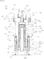
- FIG. 2 is a front cross-sectional diagram taken along the line A-A' according to the disclosure illustrated in FIG. 1
- FIG. 3 is a diagram illustrating the flow of the fuel gas in the disclosure illustrated in FIG. 2
- FIG. 4 is a diagram illustrating the flow of the exhaust gas in the disclosure illustrated in FIG. 2
- FIG. 5 is a diagram illustrating the flow of a heat transfer fluid in the disclosure illustrated in FIG. 2
- FIGS. 6 and 7 are diagrams illustrating another form of a burner in the present disclosure
- FIG. 8 is a diagram illustrating still another form of the burner in the present disclosure.
- the placement position of an inlet or an outlet may be changed slightly.
- the enhancement of the thermal efficiency and the cooling capability through the flow is an important feature of the present disclosure, it may be considered that the placement position is changed within a range that may be obviously recognized by those skilled in the art.
- an embodiment of a fuel processing apparatus 100 may be configured to include an apparatus body 200, a fuel reforming part 300, a heating part 290, a CO shift-converting reaction part 400, a PROX reaction part 500, a first heat-exchanging part 610, a second heat-exchanging part 650, and a PROX cooling part 630.
- the apparatus body 200 may be generally implemented in a cylindrical shape, and made of a material having high heat resistance and high rigidity capable of withstanding high heat and impact.
- the lower end of the apparatus body 200 may be provided with a foot plate 252 having a disc shape and a plurality of support beams 251 connected with the foot plate 252 and for supporting the apparatus body 200 so that the apparatus body 200 may be stably supported.
- the fuel reforming part 300 may be disposed in a space separately defined inside the central side of the apparatus body 200.
- the fuel reforming part 300 may be configured to include a fuel gas inlet 310, a first passage 320, a reforming catalyst layer 330, and a second passage 340.
- the fuel gas inlet 310 may be disposed to be connected with the lower end of the apparatus body 200, and the first passage 320 may be connected with the fuel gas inlet 310, and disposed inside the apparatus body 200 so that the inflow fuel gas is moved upwards.
- the reforming catalyst layer 330 may be connected with the first passage 320 and disposed at the inner central side of the apparatus body 200, and the second passage 340 may be connected with the reforming catalyst layer 330, disposed at the inside of the first passage 320, and provided so that the fuel gas having passed through the reforming catalyst layer 330 is moved downwards.
- the reforming catalyst layer 330 generates the reformed gas (one form among the fuel gases) in which hydrogen and carbon monoxide have been mixed by the hydrocarbon-steam reforming reaction (endothermic reaction; suitable catalytic reaction temperature: 400 to 650 °C).
- a concept of the reformed gas is the gas having passed through the reforming reaction among the fuel gases, contains hydrogen and carbon monoxide, and refers to the fuel gas before entering the CO shift-converting catalyst layer 410 that will be described below.
- a basic chemical reaction formula is the same as CH 4 + H 2 O ⁇ CO + 3H 2 .
- each apparatus may be slightly different from each other, but it may be applied by inferring within a range that is obvious to those skilled in the art. That is, when methane and water are mixed to flow into the reforming catalyst layer 330, the chemical reaction is performed in the catalyst layer of the fuel reforming part 300 to generate hydrogen and carbon monoxide.
- the CO shift-converting reaction part 400 may be connected with the fuel reforming part 300, and disposed at the lower side of the apparatus body 200.
- the CO shift-converting reaction part 400 may be configured to include a CO shift-converting catalyst layer 410, a third passage 420, and a fourth passage 430.
- the CO shift-converting catalyst layer 410 may be disposed along the outer circumference of the fuel reforming part 300 at the lower side of the apparatus body 200, and the third passage 420 may be disposed at the lower end of the apparatus body 200 and provided to connect the second passage 340 with the CO shift-converting catalyst layer 410.
- the fourth passage 430 may connect the CO shift-converting catalyst layer 410 with the PROX reaction part 500 at the outside of the apparatus body 200, and may be provided so that the fuel gas having passed through the CO shift-converting catalyst reaction flow to the PROX reaction part 500.
- the CO shift-converting catalyst layer 410 converts the carbon monoxide of the reformed gas generated in the reforming catalyst layer 330 into carbon dioxide through the CO shift-converting reaction (exothermic reaction; suitable catalytic reaction temperature: 1 to 250 °C), thereby reducing a carbon monoxide ratio in the fuel gas.
- a chemical reaction formula is the same as CO + H 2 O ⁇ H 2 + CO 2 .
- each apparatus may be slightly different from each other, but it may be applied by inferring within a range that is obvious to those skilled in the art.
- carbon monoxide reacts with water and additionally generates hydrogen, and carbon monoxide is shift-converted into carbon dioxide through the oxidation reaction.
- the PROX reaction part 500 may be connected with the CO shift-converting reaction part 400, and disposed at the upper side of the apparatus body 200.
- the PROX reaction part 500 may be configured to include a CO removal catalyst layer 510, a PROX inlet 520, and a PROX outlet 530.
- the CO removal catalyst layer 510 may be disposed along the outer circumference of the heating part 290 at the upper side of the apparatus body 200, and the PROX inlet 520 may be disposed at one side of the CO removal catalyst layer 510, and connected with the fourth passage 430.
- the PROX outlet 530 may be disposed at the other side of the CO removal catalyst layer 510, and provided to discharge the fuel gas having passed through the CO removal catalyst reaction.
- the CO removal catalyst layer 510 converts the carbon monoxide of the fuel gas generated in the CO shift-converting catalyst layer 410 into carbon dioxide through the carbon monoxide selective oxidation reaction (preferential oxidation reaction (PROX), exothermic reaction, suitable catalytic reaction temperature: 80 to 160°C), thereby further reducing the ratio of carbon monoxide in the fuel gas.
- the target content of carbon monoxide is equal to or smaller than 10 ppm in the fuel gas.
- a chemical reaction formula is the same as 2CO + O 2 ⁇ 2CO 2 .
- each apparatus may be slightly different from each other, but it may be applied by inferring within a range that is obvious to those skilled in the art.
- carbon monoxide reacts with oxygen to be converted into carbon dioxide, and the carbon monoxide in the fuel gas is removed.
- the heating part 290 may be disposed at the upper side of the apparatus body 200 so as to heat the fuel reforming part 300.
- the heating part 290 may be configured to include a center burner 292 connected to the lower end of a burner body 291, a heat dispersing plate 293, and an exhaust gas passage 297.
- the center burner 292 may be disposed at the upper central portion of the apparatus body 200, and the heat dispersing plate 293 may be disposed at the upper end of the fuel reforming part 300 at the lower side of the burner. Then, the exhaust gas passage 297 may be disposed along the outer circumference of the fuel reforming part 300 inside the apparatus body 200.
- FIGS. 6 to 8 illustrate another form of the heating part 290.
- a side burner 294 may be additionally disposed along the circumference of the center burner 292.
- the side burner 294 may be disposed on a side pipe 294a having a ring shape formed integrally with a connection pipe 292a connected with the center burner 292. Therefore, the side burner 294 may be radially disposed in plural.
- the heat dispersing plate 293 may be simultaneously heated by the side burner 294 as well as the center burner 292, thereby heating the reforming catalyst layer 330 more uniformly.
- the side burner 294 has been disposed on the side pipe 294a with the angle ⁇ formed in the direction of the heat dispersing plate 293.
- the heat dispersing plate 293 may be formed in a hemispherical shape protruded toward the center burner 292.
- the angle formed by the side burner 294 may be formed to be perpendicular to the surface of the heat dispersing plate 293.
- the reforming catalyst layer 330 may receive heat not only at the upper portion thereof but also the side portion thereof, such that it is possible to directly receive heat in a wider region, thereby enabling the heating more uniformly.
- the side burner 294 is also angularly disposed to be perpendicular to the surface of the heat dispersing plate 293, the energy waste during heating may be minimized.
- the present disclosure may suggest various types of burner structures, and may be applied by inferring within a range that is obvious to those skilled in the art.
- the first heat-exchanging part 610 may be connected with the heating part 290, and disposed between the heating part 290 and the CO shift-converting reaction part to be heat-exchanged between the exhaust gas discharged from the heating part 290 and the CO shift-converting reaction part.
- the first heat-exchanging part 610 may be configured to include a first heat-exchanging body 611 and a first heat transfer pipe 612.
- the first heat-exchanging body 611 may be disposed along the outer circumference of the exhaust gas passage 297, and provided to be connected with the exhaust gas passage 297 through an exhaust gas connection hole 613, and the first heat transfer pipe 612 may be disposed by being wound in plural along the inner circumference of the first heat-exchanging body 611, and provided so that the heat transfer fluid flows.
- the heat transfer fluid may be water. Specifically, it may be Deionized water (DI water) from which the ion component has been removed, and used in a steam state in the present disclosure.
- DI water Deionized water
- the PROX cooling part 630 may be disposed along the inner circumference of the PROX reaction part 500 so as to cool the PROX reaction part 500.
- the PROX cooling part 630 may be configured to include a cooler 631, a cooling fluid inlet 632, and a cooling fluid outlet 633.
- the cooler 631 may be disposed along the inner circumference of the CO removal catalyst layer 510.
- the cooling fluid inlet 632 may be disposed at one side of the cooler 631 and a portion into which the heat transfer fluid flows, and the cooling fluid outlet 633 may be disposed at the other side of the cooler 631 and a portion out which the heat transfer fluid flows.
- the second heat-exchanging part 650 may be provided to be connected between the PROX cooling part 630 and the first heat-exchanging part 610 so as to be heat-exchanged between the exhaust gas and the heat transfer fluid.
- the second heat-exchanging part 650 may be configured to include a second heat-exchanging body 651 and a second heat transfer pipe 655.
- the second heat-exchanging body 651 may be disposed along the outer circumference of the first heat-exchanging body 611, and provided with an inflow hole into which the heat transfer fluid flows and an outflow hole out which the heat transfer fluid flows. Then, the second heat transfer pipe 655 may be disposed at the second heat-exchanging body 651, connected with the first heat-exchanging body 611, and provided so that the exhaust gas flows.
- the outflow hole of the second heat-exchanging body 651 may be connected with the cooling fluid inlet 632, and the cooling fluid outlet 633 may be connected with the fuel gas inlet 310.
- connection structure which will be described in detail with reference to FIGS. 4 and 5 .
- a configuration of the present disclosure is as described above, and hereinafter, the enhancement of the overall heat efficiency and the cooling performance through the operating method of the present disclosure will be described by reviewing the flow of the fuel gas, the heat transfer fluid, and the exhaust gas.
- the fuel is supplied from a fuel supply part 230, and the fuel is heated through the heat-exchange with the exhaust gas in the first heat-exchanging part 610 and mixed with the heat transfer fluid (water in a steam state) flowing out from a first outflow hole 615 to flow to the fuel gas inlet 310 disposed at the lower end of the apparatus body 200.
- the fuel is methane, and the fuel gas is in a mixed state of methane and water in the steam state.
- the fuel gas flowing into the fuel gas inlet 310 flows into the first passage 320 formed at the central side of the apparatus body 200.
- the fuel gas which has been moved upwards along the first passage 320, reaches the reforming catalyst layer 330.
- Hydrogen and carbon monoxide are generated through the reforming reaction in the reforming catalyst layer 330, as in the above chemical reaction formula.
- the heat dispersing plate 293 is heated through the ignition of the center burner 292, and the heat dispersing plate 293 transfers heat to the reforming catalyst layer 330 appropriately, such that the reforming catalyst layer 330 keeps 400 to 650°C that is the suitable reaction temperature.
- the fuel gas (reformed gas) having passed through the reforming reaction is collected in the second passage 340 formed at the inside of the first passage 320 to be moved downwards from the apparatus body 200 again.
- the third passage 420 is formed horizontally at the lower end of the second passage 340, and the fuel gas moves along the third passage 420 in the outer circumferential direction of the apparatus body 200, and then flows into the CO shift-converting catalyst layer 410.
- the carbon monoxide of the fuel gas is further shift-converted into carbon dioxide through the oxidation reaction in the CO shift-converting catalyst layer 410.
- heat is supplied from the exhaust gas flowing through the first heat-exchanging body 611 in order to form the suitable reaction temperature. Therefore, 180 to 250°C that is the suitable reaction temperature is kept.
- the fuel gas having passed through the CO shift-converting catalyst layer 410 now flows to the fourth passage 430, and flows into the CO removal catalyst layer 510 through the PROX inlet 520 connected with the fourth passage 430.
- the carbon monoxide content in the fuel gas is reduced to 10 ppm or less through the carbon monoxide selective oxidation reaction of the fuel gas in the CO removal catalyst layer 510, and the fuel gas flows into a fuel cell F through the PROX outlet 530 formed at the opposite side after flowing in the circumferential direction thereof.
- the CO removal catalyst layer 510 heat-exchanges with the cooler 631 of the PROX cooling part 630 disposed along the outer circumference of the CO removal catalyst layer 510. Since the carbon monoxide selective oxidation reaction is the exothermic reaction, heat is absorbed by the heat transfer fluid flowing through the cooler 631, thereby keeping 80 to 160°C that is the suitable reaction temperature.
- the flow of the exhaust gas is illustrated, and the heating material (methane + air) through a heating material supplying part 210 is injected into the center burner 292 through a heating material injecting port 295.
- non-reaction exhaust gas is injected from the fuel cell stack through a non-reaction raw material injecting port 296.
- the non-reaction raw material may be a mixture of hydrogen and other gases, and in the stack, typically 70 to 80% of hydrogen is consumed and 20 to 30% thereof is discharged in a non-reaction state, thereby increasing heating raw material reaction performance by injecting hydrogen therein.
- the injected heating raw material and non-reaction raw material are ignited in the center burner 292 to heat the heat dispersing plate 293 and used for forming the suitable reaction temperature of the reforming catalyst layer 330.
- the exhaust gas discharged after combustion is moved downwards along the exhaust gas passage 297 formed along the outer circumference of the first passage 320 and then flows into the first heat-exchanging body 611 through the exhaust gas connection hole 613.
- the exhaust gas moves upwards inside the first heat-exchanging body 611 and transfers heat to the CO shift-converting catalyst layer 410.
- the first heat transfer pipe 612 provided to be wound in plural in the circumference direction thereof is disposed inside the first heat-exchanging body 611, and the heat transfer fluid flows inside the first heat transfer pipe 612.
- the exhaust gas also transfers heat to the heat transfer fluid flowing inside the first heat transfer pipe 612 to heat the heat transfer fluid.
- the first heat-exchanging body 611 is connected with a second heat transfer pipe 655 by an exhaust gas connection pipe 656, and the exhaust gas flowing through the first heat-exchanging body 611 flows through the second heat transfer pipe 655, and is discharged into the atmosphere A through an exhaust gas outlet 657.
- the second heat transfer pipe 655 is disposed inside the second heat-exchanging body 651 so that heat may be transferred to the heat transfer fluid injected into the second heat-exchanging body 651 while flowing inside the second heat transfer pipe 655.
- the exhaust gas not only transfers heat to the heat transfer fluid gradually in the first and second heat-exchanging parts 610, 650, but also transfers heat to the CO shift-converting catalyst layer 410, thereby maximally recycling the waste heat of the exhaust gas.
- the heat transfer fluid is supplied through a heat transfer fluid supplying part 220.
- the heat transfer fluid used in the present disclosure is water but is not limited thereto.
- the heat transfer fluid flows into the second heat-exchanging body 651 through a second inflow hole 652. At this time, the heat transfer fluid receives heat from the exhaust gas flowing through the second heat transfer pipe 655 to be heated.
- the heat transfer fluid flows in the circumferential direction along the inside of the second heat-exchanging body 651, then is discharged through a second outflow hole 653 formed at the opposite side thereof, and flows in the direction of the cooling fluid inlet 632 connected with the second outflow hole 653.
- the cooling fluid refers to the heat transfer fluid, but since it is used to cool the CO removal catalyst layer 510, the expression of the cooling fluid is used in combination.
- the heat transfer fluid supplied to the cooling fluid inlet 632 cools the CO removal catalyst layer 510 while flowing through the circumferentially disposed cooler 631. Since the heat transfer fluid is water and the steam temperature is about 100°C, heat is taken away from the exothermic reaction of the carbon monoxide selective oxidation reaction in order to keep the suitable reaction temperature of 80 to 160°C of the CO removal catalyst layer 510.
- the heat transfer fluid flows out through the cooling fluid outlet 633 disposed at the opposite side of the cooler 631, and at this time, since the cooling fluid outlet 633 is connected with the first inflow hole 614, the heat transfer fluid flows into the first heat transfer pipe 612 through the first inflow hole 614.
- the heat transfer fluid is heated by receiving heat from the exhaust gas flowing inside the first heat-exchanging body 611 while flowing inside the first heat transfer pipe 612.
- the heat transfer fluid is discharged into the outside through the first outflow hole 615 connected with the first heat transfer pipe 612, mixed with the fuel supplied from the fuel supplying part 230 to become the fuel gas to flow into the apparatus body 200 through the fuel gas inlet 310 again.
- the heat transfer fluid receives heat from the exhaust gas while flowing through the second heat-exchanging body 651 and the first heat transfer pipe 612, except for when being initially supplied from the heat transfer fluid supplying part 220, and receives heat from the CO removal catalyst layer 510 while flowing through the cooler 631, such that most of the states may be kept in the steam state.
- the present disclosure maximally recovers the waste heat of the exhaust gas through the optimal placement and the operating method of various catalyst layers, the heat-exchange, and the cooling portions, and keeps the suitable reaction temperature of various catalyst layers, thereby enhancing the thermal efficiency and the cooling capability of the fuel processing apparatus 100.
- the present disclosure relates to a fuel processing apparatus, and there is an industrial applicability because it corresponds to the technical field applied to a fuel cell system.
Landscapes
- Chemical & Material Sciences (AREA)
- Chemical Kinetics & Catalysis (AREA)
- Organic Chemistry (AREA)
- Engineering & Computer Science (AREA)
- General Chemical & Material Sciences (AREA)
- Sustainable Energy (AREA)
- Sustainable Development (AREA)
- Electrochemistry (AREA)
- Life Sciences & Earth Sciences (AREA)
- Manufacturing & Machinery (AREA)
- Combustion & Propulsion (AREA)
- Inorganic Chemistry (AREA)
- Health & Medical Sciences (AREA)
- General Health & Medical Sciences (AREA)
- Hydrogen, Water And Hydrids (AREA)
- Fuel Cell (AREA)
Abstract
Description
- The present disclosure relates to a fuel processing apparatus, and more particularly, to a fuel processing apparatus, which is advantageous to enhance the heat transfer and the cooling efficiency through the optimal placement, stably perform the reforming reaction and the CO removing reaction, and miniaturize the apparatus.
- Generally, a fuel processing apparatus used in a fuel cell system may be configured to include a reformer, a CO shift converter, and a CO remover.
- The reformer reacts the fuel gas such as methane with steam to generate hydrogen through the endothermic reaction through a burner. Herein, the hydrogen generated in the reformer usually contains carbon monoxide.
- When the hydrogen containing such carbon monoxide is supplied to the fuel cell system as it is, poisoning may occur in the reaction catalyst inside a fuel cell, thereby deteriorating the performance of the fuel cell.
- Therefore, it is necessary to remove carbon monoxide before supplying the generated hydrogen to the fuel cell system, and at this time, the CO shift converter and the CO remover are used.
- The CO shift converter reacts carbon monoxide with steam to convert carbon monoxide into carbon dioxide, and additionally generates hydrogen. While passing through the CO shift converter, carbon monoxide contained in hydrogen is reduced from 10 ∼ 15% to 1% or less.
- Hydrogen having passed through the CO shift converter flows into the CO remover again, and converts carbon monoxide into carbon dioxide through the selective oxidation reaction with respect to carbon monoxide to be usually reduced to 10 ppm or less.
- As described above, the fuel gas from which the CO has been removed is supplied to an anode of a fuel cell stack, and air (oxygen) is supplied to a cathode, such that the electrochemical reaction is performed through an electrolyte membrane to generate a current, and additionally, water and heat are generated.
- The generated current is collected through a current collector and converted into an alternating current in an inverter to be supplied to a load, and the generated heat is stored as hot water through a heat exchanger to be also used for hot water supply and heating.
- Currently, fuel cells are being used for a wider range of applications, and advanced countries are continuously investing to improve the fuel cells and enhance the efficiency.
- KOREA also regards the fuel cell as a future eco-friendly energy source, and is actively investing in it.
- Therefore, it is continuously seeking to enhance the performance of the fuel processing apparatus for efficiently generating hydrogen, which is the main material of the fuel cell in the related technical field. The research has been continued to further miniaturize the apparatus, to enhance the thermal efficiency by recovering the waste heat of the exhaust gas between the reformer, the CO shift converter, and the CO remover internally disposed in the apparatus, and to enhance the cooling capability by the heat transfer therebetween.
- The present disclosure is intended to solve the above problem, and an object of the present disclosure is to provide to a fuel processing apparatus, which is advantageous to enhance the heat transfer and the cooling efficiency through the optimal placement, stably perform the reforming reaction and the CO removing reaction, and miniaturize the apparatus.
- The present disclosure for achieving the objects relates to a fuel processing apparatus, and may include an apparatus body, a fuel reforming part disposed at the central side of the apparatus body, a heating part disposed at the upper side of the apparatus body so as to heat the fuel reforming part, a CO shift-converting reaction part connected with the fuel reforming part, and disposed at the lower side of the apparatus body, and a PROX reaction part connected with the CO shift-converting reaction part, and disposed at the upper side of the apparatus body.
- In addition, in an embodiment of the present disclosure, the fuel reforming part may include a fuel gas inlet disposed to be connected with the lower end of the apparatus body, a first passage connected with the fuel gas inlet, and disposed inside the apparatus body so that the inflow fuel gas is moved upwards, a reforming catalyst layer connected with the first passage, and disposed at the inner central side of the apparatus body, and a second passage connected with the reforming catalyst layer, disposed at the inside of the first passage, and provided so that the fuel gas having passed through the reforming catalyst reaction is moved downwards.
- In addition, in an embodiment of the present disclosure, the CO shift-converting reaction part may include a CO shift-converting catalyst layer disposed along the outer circumference of the fuel reforming part at the lower side of the apparatus body, a third passage disposed at the lower end of the apparatus body, and for connecting the second passage with the CO shift-converting catalyst layer, and a fourth passage for connecting the CO shift-converting catalyst layer with the PROX reaction part at the outside of the apparatus body, and provided so that the fuel gas having passed through the CO shift-converting catalyst reaction flows to the PROX reaction part.
- In addition, in an embodiment of the present disclosure, the PROX reaction part may include a CO removal catalyst layer disposed along the outer circumference of the heating part at the upper side of the apparatus body, a PROX inlet disposed at one side of the CO removal catalyst layer, and connected with the fourth passage, and a PROX outlet disposed at the other side of the CO removal catalyst layer, and for discharging the fuel gas having passed through the CO removal catalyst reaction.
- In addition, in an embodiment of the present disclosure, the heating part may include a center burner disposed at the upper central portion of the apparatus body, a heat dispersing plate disposed at the upper end of the reforming catalyst layer at the lower side of the burner, and an exhaust gas passage disposed along the outer circumference of the fuel reforming part at the inside of the apparatus body.
- In addition, in an embodiment of the present disclosure, the heating part may further include a side burner disposed along the circumference of the center burner.
- In addition, in an embodiment of the present disclosure, the heat dispersing plate may have a hemispherical shape protruded toward the center burner, and the side burner may be disposed to be perpendicular to the surface of the heat dispersing plate.
- In addition, in an embodiment of the present disclosure, the fuel processing apparatus may further include a first heat-exchanging part connected with the heating part, and disposed between the heating part and the CO shift-converting reaction part so as to be heat-exchanged between the exhaust gas discharged from the heating part and the CO shift-converting reaction part.
- In addition, in an embodiment of the present disclosure, the first heat-exchanging part may include a first heat-exchanging body disposed along the outer circumference of the exhaust gas passage, and connected with the exhaust gas passage, and a first heat transfer pipe disposed to be wound in plural along the inner circumference of the first heat-exchanging body, and through which heat transfer fluid flows, and heat may be exchanged between the exhaust gas flowing through the first heat-exchanging body and the heat transfer fluid flowing through the first heat transfer pipe.
- In addition, in an embodiment of the present disclosure, the fuel processing apparatus may further include a PROX cooling part disposed along the inner circumference of the PROX reaction part so as to cool the PROX reaction part.
- In addition, in an embodiment of the present disclosure, the PROX cooling part may include a cooler disposed along the inner circumference of the CO removal catalyst layer, a cooling fluid inlet disposed at one side of the cooler, and into which the heat transfer fluid flows, and a cooling fluid outlet disposed at the other side of the cooler, and out which the heat transfer fluid flows.
- In addition, in an embodiment of the present disclosure, the fuel processing apparatus may further include a second heat-exchanging part connected between the PROX cooling part and the first heat-exchanging part so as to be heat-exchanged between the exhaust gas and the heat transfer fluid.
- In addition, in an embodiment of the present disclosure, the second heat-exchanging part may include a second heat-exchanging body disposed along the outer circumference of the first heat-exchanging body, and having an inflow hole into which the heat transfer fluid flows and an outflow hole out which the heat transfer fluid flows, and a second heat transfer pipe disposed at the second heat-exchanging body, connected with the first heat-exchanging body, and through which the exhaust gas flows.
- In addition, in an embodiment of the present disclosure, the outflow hole of the second heat-exchanging body may be configured to be connected with the cooling fluid inlet.
- In addition, in an embodiment of the present disclosure, the cooling fluid outlet may be configured to be connected with the fuel gas inlet.
- According to the present disclosure, it is possible to enhance the heat transfer by the recovery of the waste heat of the exhaust gas and the cooling efficiency of the catalyst layer in which the exothermic reaction is performed through the optimal placement of the fuel reforming part, the CO shift-converting reaction part, and the PROX reaction part.
- This makes it possible to stably perform the reforming reaction and the CO removing reaction with respect to the fuel used in the fuel cell inside the apparatus, and to ultimately enhance the performance of the apparatus.
- In addition, it is possible to miniaturize the apparatus through the optimal placement.
-
-
FIG. 1 is a perspective diagram of a fuel processing apparatus according to the present disclosure. -
FIG. 2 is a front cross-sectional diagram taken along the line A-A' according to the disclosure illustrated inFIG. 1 . -
FIG. 3 is a diagram illustrating the flow of the fuel gas in the disclosure illustrated inFIG. 2 . -
FIG. 4 is a diagram illustrating the flow of the exhaust gas in the disclosure illustrated inFIG. 2 . -
FIG. 5 is a diagram illustrating the flow of a heat transfer fluid in the disclosure illustrated inFIG. 2 . -
FIGS. 6 and7 are diagrams illustrating another form of a burner in the present disclosure. -
FIG. 8 is a diagram illustrating still another form of the burner in the present disclosure. - Hereinafter, preferred embodiments of a fuel processing apparatus according to the present disclosure will be described in detail with reference to the accompanying drawings.
-
FIG. 1 is a perspective diagram of a fuel processing apparatus according to the present disclosure,FIG. 2 is a front cross-sectional diagram taken along the line A-A' according to the disclosure illustrated inFIG. 1 ,FIG. 3 is a diagram illustrating the flow of the fuel gas in the disclosure illustrated inFIG. 2 ,FIG. 4 is a diagram illustrating the flow of the exhaust gas in the disclosure illustrated inFIG. 2 ,FIG. 5 is a diagram illustrating the flow of a heat transfer fluid in the disclosure illustrated inFIG. 2 ,FIGS. 6 and7 are diagrams illustrating another form of a burner in the present disclosure, andFIG. 8 is a diagram illustrating still another form of the burner in the present disclosure. - To facilitate understanding of the flow of the fuel gas, the heat transfer fluid, and the exhaust gas in the figure, the placement position of an inlet or an outlet may be changed slightly. However, since the enhancement of the thermal efficiency and the cooling capability through the flow is an important feature of the present disclosure, it may be considered that the placement position is changed within a range that may be obviously recognized by those skilled in the art.
- Referring to
FIGS. 1 to 5 , an embodiment of afuel processing apparatus 100 according to the present disclosure may be configured to include anapparatus body 200, afuel reforming part 300, aheating part 290, a CO shift-converting reaction part 400, aPROX reaction part 500, a first heat-exchangingpart 610, a second heat-exchangingpart 650, and aPROX cooling part 630. - Firstly, the
apparatus body 200 may be generally implemented in a cylindrical shape, and made of a material having high heat resistance and high rigidity capable of withstanding high heat and impact. In addition, the lower end of theapparatus body 200 may be provided with afoot plate 252 having a disc shape and a plurality ofsupport beams 251 connected with thefoot plate 252 and for supporting theapparatus body 200 so that theapparatus body 200 may be stably supported. - Next, referring to
FIG. 2 , thefuel reforming part 300 may be disposed in a space separately defined inside the central side of theapparatus body 200. - The
fuel reforming part 300 may be configured to include afuel gas inlet 310, afirst passage 320, a reformingcatalyst layer 330, and asecond passage 340. - The
fuel gas inlet 310 may be disposed to be connected with the lower end of theapparatus body 200, and thefirst passage 320 may be connected with thefuel gas inlet 310, and disposed inside theapparatus body 200 so that the inflow fuel gas is moved upwards. - The reforming
catalyst layer 330 may be connected with thefirst passage 320 and disposed at the inner central side of theapparatus body 200, and thesecond passage 340 may be connected with the reformingcatalyst layer 330, disposed at the inside of thefirst passage 320, and provided so that the fuel gas having passed through the reformingcatalyst layer 330 is moved downwards. - The reforming
catalyst layer 330 generates the reformed gas (one form among the fuel gases) in which hydrogen and carbon monoxide have been mixed by the hydrocarbon-steam reforming reaction (endothermic reaction; suitable catalytic reaction temperature: 400 to 650 °C). - A concept of the reformed gas is the gas having passed through the reforming reaction among the fuel gases, contains hydrogen and carbon monoxide, and refers to the fuel gas before entering the CO shift-converting
catalyst layer 410 that will be described below. - A basic chemical reaction formula is the same as CH4 + H2O → CO + 3H2. Of course, each apparatus may be slightly different from each other, but it may be applied by inferring within a range that is obvious to those skilled in the art. That is, when methane and water are mixed to flow into the reforming
catalyst layer 330, the chemical reaction is performed in the catalyst layer of thefuel reforming part 300 to generate hydrogen and carbon monoxide. - The flow of the fuel gas on the
fuel processing apparatus 100 will be described in detail with reference toFIG. 3 . - Next, the CO shift-converting
reaction part 400 may be connected with thefuel reforming part 300, and disposed at the lower side of theapparatus body 200. The CO shift-convertingreaction part 400 may be configured to include a CO shift-convertingcatalyst layer 410, athird passage 420, and afourth passage 430. - The CO shift-converting
catalyst layer 410 may be disposed along the outer circumference of thefuel reforming part 300 at the lower side of theapparatus body 200, and thethird passage 420 may be disposed at the lower end of theapparatus body 200 and provided to connect thesecond passage 340 with the CO shift-convertingcatalyst layer 410. - The
fourth passage 430 may connect the CO shift-convertingcatalyst layer 410 with thePROX reaction part 500 at the outside of theapparatus body 200, and may be provided so that the fuel gas having passed through the CO shift-converting catalyst reaction flow to thePROX reaction part 500. - The CO shift-converting
catalyst layer 410 converts the carbon monoxide of the reformed gas generated in the reformingcatalyst layer 330 into carbon dioxide through the CO shift-converting reaction (exothermic reaction; suitable catalytic reaction temperature: 1 to 250 °C), thereby reducing a carbon monoxide ratio in the fuel gas. - A chemical reaction formula is the same as CO + H2O → H2 + CO2. Of course, each apparatus may be slightly different from each other, but it may be applied by inferring within a range that is obvious to those skilled in the art.
- That is, carbon monoxide reacts with water and additionally generates hydrogen, and carbon monoxide is shift-converted into carbon dioxide through the oxidation reaction.
- Next, the
PROX reaction part 500 may be connected with the CO shift-convertingreaction part 400, and disposed at the upper side of theapparatus body 200. ThePROX reaction part 500 may be configured to include a COremoval catalyst layer 510, aPROX inlet 520, and aPROX outlet 530. - The CO
removal catalyst layer 510 may be disposed along the outer circumference of theheating part 290 at the upper side of theapparatus body 200, and thePROX inlet 520 may be disposed at one side of the COremoval catalyst layer 510, and connected with thefourth passage 430. In addition, thePROX outlet 530 may be disposed at the other side of the COremoval catalyst layer 510, and provided to discharge the fuel gas having passed through the CO removal catalyst reaction. - The CO
removal catalyst layer 510 converts the carbon monoxide of the fuel gas generated in the CO shift-convertingcatalyst layer 410 into carbon dioxide through the carbon monoxide selective oxidation reaction (preferential oxidation reaction (PROX), exothermic reaction, suitable catalytic reaction temperature: 80 to 160°C), thereby further reducing the ratio of carbon monoxide in the fuel gas. At this time, the target content of carbon monoxide is equal to or smaller than 10 ppm in the fuel gas. - A chemical reaction formula is the same as 2CO + O2 → 2CO2. Of course, each apparatus may be slightly different from each other, but it may be applied by inferring within a range that is obvious to those skilled in the art.
- That is, carbon monoxide reacts with oxygen to be converted into carbon dioxide, and the carbon monoxide in the fuel gas is removed.
- Details of the fuel gas flow in the
fuel reforming part 300, the CO shift-convertingreaction part 400, and thePROX reaction part 500 will be described with reference toFIG. 3 . - Next, referring to
FIG. 2 , theheating part 290 may be disposed at the upper side of theapparatus body 200 so as to heat thefuel reforming part 300. Theheating part 290 may be configured to include acenter burner 292 connected to the lower end of aburner body 291, aheat dispersing plate 293, and anexhaust gas passage 297. - The
center burner 292 may be disposed at the upper central portion of theapparatus body 200, and theheat dispersing plate 293 may be disposed at the upper end of thefuel reforming part 300 at the lower side of the burner. Then, theexhaust gas passage 297 may be disposed along the outer circumference of thefuel reforming part 300 inside theapparatus body 200. - Meanwhile,
FIGS. 6 to 8 illustrate another form of theheating part 290. - Firstly, referring to
FIGS. 6 and7 , aside burner 294 may be additionally disposed along the circumference of thecenter burner 292. - The
side burner 294 may be disposed on aside pipe 294a having a ring shape formed integrally with aconnection pipe 292a connected with thecenter burner 292. Therefore, theside burner 294 may be radially disposed in plural. - Through this placement, the
heat dispersing plate 293 may be simultaneously heated by theside burner 294 as well as thecenter burner 292, thereby heating the reformingcatalyst layer 330 more uniformly. - Next, referring to
FIG. 8 , it may be seen that theside burner 294 has been disposed on theside pipe 294a with the angle θ formed in the direction of theheat dispersing plate 293. At this time, theheat dispersing plate 293 may be formed in a hemispherical shape protruded toward thecenter burner 292. Herein, the angle formed by theside burner 294 may be formed to be perpendicular to the surface of theheat dispersing plate 293. - When the
heat dispersing plate 293 is formed in a hemispherical shape, the reformingcatalyst layer 330 may receive heat not only at the upper portion thereof but also the side portion thereof, such that it is possible to directly receive heat in a wider region, thereby enabling the heating more uniformly. - Since the
side burner 294 is also angularly disposed to be perpendicular to the surface of theheat dispersing plate 293, the energy waste during heating may be minimized. - As described above, the present disclosure may suggest various types of burner structures, and may be applied by inferring within a range that is obvious to those skilled in the art.
- Next, the first heat-exchanging
part 610 may be connected with theheating part 290, and disposed between theheating part 290 and the CO shift-converting reaction part to be heat-exchanged between the exhaust gas discharged from theheating part 290 and the CO shift-converting reaction part. - The first heat-exchanging
part 610 may be configured to include a first heat-exchanging body 611 and a firstheat transfer pipe 612. - The first heat-exchanging body 611 may be disposed along the outer circumference of the
exhaust gas passage 297, and provided to be connected with theexhaust gas passage 297 through an exhaustgas connection hole 613, and the firstheat transfer pipe 612 may be disposed by being wound in plural along the inner circumference of the first heat-exchanging body 611, and provided so that the heat transfer fluid flows. - Herein, the heat transfer fluid may be water. Specifically, it may be Deionized water (DI water) from which the ion component has been removed, and used in a steam state in the present disclosure.
- Next, the
PROX cooling part 630 may be disposed along the inner circumference of thePROX reaction part 500 so as to cool thePROX reaction part 500. ThePROX cooling part 630 may be configured to include a cooler 631, a coolingfluid inlet 632, and a coolingfluid outlet 633. - The cooler 631 may be disposed along the inner circumference of the CO
removal catalyst layer 510. The coolingfluid inlet 632 may be disposed at one side of the cooler 631 and a portion into which the heat transfer fluid flows, and the coolingfluid outlet 633 may be disposed at the other side of the cooler 631 and a portion out which the heat transfer fluid flows. - Next, the second heat-exchanging
part 650 may be provided to be connected between thePROX cooling part 630 and the first heat-exchangingpart 610 so as to be heat-exchanged between the exhaust gas and the heat transfer fluid. The second heat-exchangingpart 650 may be configured to include a second heat-exchangingbody 651 and a secondheat transfer pipe 655. - The second heat-exchanging
body 651 may be disposed along the outer circumference of the first heat-exchanging body 611, and provided with an inflow hole into which the heat transfer fluid flows and an outflow hole out which the heat transfer fluid flows. Then, the secondheat transfer pipe 655 may be disposed at the second heat-exchangingbody 651, connected with the first heat-exchanging body 611, and provided so that the exhaust gas flows. - Meanwhile, the outflow hole of the second heat-exchanging
body 651 may be connected with the coolingfluid inlet 632, and the coolingfluid outlet 633 may be connected with thefuel gas inlet 310. - The flow of the heat transfer fluid and the exhaust gas is guided through the connection structure, which will be described in detail with reference to
FIGS. 4 and5 . - A configuration of the present disclosure is as described above, and hereinafter, the enhancement of the overall heat efficiency and the cooling performance through the operating method of the present disclosure will be described by reviewing the flow of the fuel gas, the heat transfer fluid, and the exhaust gas.
- Firstly, referring to
FIG. 3 , the flow of the fuel gas in the present disclosure is illustrated. - The fuel is supplied from a
fuel supply part 230, and the fuel is heated through the heat-exchange with the exhaust gas in the first heat-exchangingpart 610 and mixed with the heat transfer fluid (water in a steam state) flowing out from afirst outflow hole 615 to flow to thefuel gas inlet 310 disposed at the lower end of theapparatus body 200. Herein, the fuel is methane, and the fuel gas is in a mixed state of methane and water in the steam state. - The fuel gas flowing into the
fuel gas inlet 310 flows into thefirst passage 320 formed at the central side of theapparatus body 200. The fuel gas, which has been moved upwards along thefirst passage 320, reaches the reformingcatalyst layer 330. - Hydrogen and carbon monoxide are generated through the reforming reaction in the reforming
catalyst layer 330, as in the above chemical reaction formula. At this time, in order to form the suitable reaction temperature of the reformingcatalyst layer 330, theheat dispersing plate 293 is heated through the ignition of thecenter burner 292, and theheat dispersing plate 293 transfers heat to the reformingcatalyst layer 330 appropriately, such that the reformingcatalyst layer 330 keeps 400 to 650°C that is the suitable reaction temperature. - Now, the fuel gas (reformed gas) having passed through the reforming reaction is collected in the
second passage 340 formed at the inside of thefirst passage 320 to be moved downwards from theapparatus body 200 again. - The
third passage 420 is formed horizontally at the lower end of thesecond passage 340, and the fuel gas moves along thethird passage 420 in the outer circumferential direction of theapparatus body 200, and then flows into the CO shift-convertingcatalyst layer 410. - The carbon monoxide of the fuel gas is further shift-converted into carbon dioxide through the oxidation reaction in the CO shift-converting
catalyst layer 410. At this time, heat is supplied from the exhaust gas flowing through the first heat-exchanging body 611 in order to form the suitable reaction temperature. Therefore, 180 to 250°C that is the suitable reaction temperature is kept. - The fuel gas having passed through the CO shift-converting
catalyst layer 410 now flows to thefourth passage 430, and flows into the COremoval catalyst layer 510 through thePROX inlet 520 connected with thefourth passage 430. - The carbon monoxide content in the fuel gas is reduced to 10 ppm or less through the carbon monoxide selective oxidation reaction of the fuel gas in the CO
removal catalyst layer 510, and the fuel gas flows into a fuel cell F through thePROX outlet 530 formed at the opposite side after flowing in the circumferential direction thereof. - At this time, in order to form the suitable reaction temperature of the CO
removal catalyst layer 510, the COremoval catalyst layer 510 heat-exchanges with the cooler 631 of thePROX cooling part 630 disposed along the outer circumference of the COremoval catalyst layer 510. Since the carbon monoxide selective oxidation reaction is the exothermic reaction, heat is absorbed by the heat transfer fluid flowing through the cooler 631, thereby keeping 80 to 160°C that is the suitable reaction temperature. - Next, referring to
FIGS. 4 and5 , the flow of the exhaust gas and the heat transfer fluid in the present disclosure is illustrated. - Firstly, referring to
FIG. 4 , the flow of the exhaust gas is illustrated, and the heating material (methane + air) through a heatingmaterial supplying part 210 is injected into thecenter burner 292 through a heatingmaterial injecting port 295. - Meanwhile, non-reaction exhaust gas is injected from the fuel cell stack through a non-reaction raw
material injecting port 296. The non-reaction raw material may be a mixture of hydrogen and other gases, and in the stack, typically 70 to 80% of hydrogen is consumed and 20 to 30% thereof is discharged in a non-reaction state, thereby increasing heating raw material reaction performance by injecting hydrogen therein. - The injected heating raw material and non-reaction raw material are ignited in the
center burner 292 to heat theheat dispersing plate 293 and used for forming the suitable reaction temperature of the reformingcatalyst layer 330. - The exhaust gas discharged after combustion is moved downwards along the
exhaust gas passage 297 formed along the outer circumference of thefirst passage 320 and then flows into the first heat-exchanging body 611 through the exhaustgas connection hole 613. - The exhaust gas moves upwards inside the first heat-exchanging body 611 and transfers heat to the CO shift-converting
catalyst layer 410. - Then, at this time, the first
heat transfer pipe 612 provided to be wound in plural in the circumference direction thereof is disposed inside the first heat-exchanging body 611, and the heat transfer fluid flows inside the firstheat transfer pipe 612. - The exhaust gas also transfers heat to the heat transfer fluid flowing inside the first
heat transfer pipe 612 to heat the heat transfer fluid. - The first heat-exchanging body 611 is connected with a second
heat transfer pipe 655 by an exhaustgas connection pipe 656, and the exhaust gas flowing through the first heat-exchanging body 611 flows through the secondheat transfer pipe 655, and is discharged into the atmosphere A through anexhaust gas outlet 657. - Of course, the second
heat transfer pipe 655 is disposed inside the second heat-exchangingbody 651 so that heat may be transferred to the heat transfer fluid injected into the second heat-exchangingbody 651 while flowing inside the secondheat transfer pipe 655. - Through the above-described structural flow, the exhaust gas not only transfers heat to the heat transfer fluid gradually in the first and second heat-exchanging
parts catalyst layer 410, thereby maximally recycling the waste heat of the exhaust gas. - Next, referring to
FIG. 5 , the flow of the heat transfer fluid in the present disclosure is illustrated. - Firstly, the heat transfer fluid is supplied through a heat transfer
fluid supplying part 220. The heat transfer fluid used in the present disclosure is water but is not limited thereto. - The heat transfer fluid flows into the second heat-exchanging
body 651 through asecond inflow hole 652. At this time, the heat transfer fluid receives heat from the exhaust gas flowing through the secondheat transfer pipe 655 to be heated. - Thereafter, the heat transfer fluid flows in the circumferential direction along the inside of the second heat-exchanging
body 651, then is discharged through asecond outflow hole 653 formed at the opposite side thereof, and flows in the direction of the coolingfluid inlet 632 connected with thesecond outflow hole 653. - Herein, the cooling fluid refers to the heat transfer fluid, but since it is used to cool the CO
removal catalyst layer 510, the expression of the cooling fluid is used in combination. - The heat transfer fluid supplied to the cooling
fluid inlet 632 cools the COremoval catalyst layer 510 while flowing through the circumferentially disposed cooler 631. Since the heat transfer fluid is water and the steam temperature is about 100°C, heat is taken away from the exothermic reaction of the carbon monoxide selective oxidation reaction in order to keep the suitable reaction temperature of 80 to 160°C of the COremoval catalyst layer 510. - Thereafter, the heat transfer fluid flows out through the cooling
fluid outlet 633 disposed at the opposite side of the cooler 631, and at this time, since the coolingfluid outlet 633 is connected with thefirst inflow hole 614, the heat transfer fluid flows into the firstheat transfer pipe 612 through thefirst inflow hole 614. - The heat transfer fluid is heated by receiving heat from the exhaust gas flowing inside the first heat-exchanging body 611 while flowing inside the first
heat transfer pipe 612. - Thereafter, the heat transfer fluid is discharged into the outside through the
first outflow hole 615 connected with the firstheat transfer pipe 612, mixed with the fuel supplied from thefuel supplying part 230 to become the fuel gas to flow into theapparatus body 200 through thefuel gas inlet 310 again. - Then, the above-described flow of the fuel gas proceeds.
- The heat transfer fluid receives heat from the exhaust gas while flowing through the second heat-exchanging
body 651 and the firstheat transfer pipe 612, except for when being initially supplied from the heat transferfluid supplying part 220, and receives heat from the COremoval catalyst layer 510 while flowing through the cooler 631, such that most of the states may be kept in the steam state. - As described above, the present disclosure maximally recovers the waste heat of the exhaust gas through the optimal placement and the operating method of various catalyst layers, the heat-exchange, and the cooling portions, and keeps the suitable reaction temperature of various catalyst layers, thereby enhancing the thermal efficiency and the cooling capability of the
fuel processing apparatus 100. - The above-described description is only illustrative of the specific embodiments of the fuel processing apparatus.
- Therefore, it may be easily understood by those skilled in the art that the substitution and modification of the present disclosure may be made in various forms without departing from the scope of the disclosure as defined in the following claims.
- The present disclosure relates to a fuel processing apparatus, and there is an industrial applicability because it corresponds to the technical field applied to a fuel cell system.
Claims (14)
- A fuel processing apparatus, comprising:an apparatus body;a fuel reforming part disposed at the central side of the apparatus body;a heating part disposed at the upper side of the apparatus body so as to heat the fuel reforming part;a CO shift-converting reaction part connected with the fuel reforming part, and disposed at the lower side of the apparatus body; anda PROX reaction part connected with the CO shift-converting reaction part, and disposed at the upper side of the apparatus body.
- The fuel processing apparatus of claim 1,
wherein the fuel reforming part comprises
a fuel gas inlet disposed to be connected with the lower end of the apparatus body;
a first passage connected with the fuel gas inlet, and disposed inside the apparatus body so that the inflow fuel gas is moved upwards;
a reforming catalyst layer connected with the first passage, and disposed at the inner central side of the apparatus body; and
a second passage connected with the reforming catalyst layer, disposed at the inside of the first passage, and provided so that the fuel gas having passed through the reforming catalyst reaction is moved downwards. - The fuel processing apparatus of claim 2,
wherein the CO shift-converting reaction part comprises
a CO shift-converting catalyst layer disposed along the outer circumference of the fuel reforming part at the lower side of the apparatus body;
a third passage disposed at the lower end of the apparatus body, and for connecting the second passage with the CO shift-converting catalyst layer; and
a fourth passage for connecting the CO shift-converting catalyst layer with the PROX reaction part at the outside of the apparatus body, and provided so that the fuel gas having passed through the CO shift-converting catalyst reaction flows to the PROX reaction part. - The fuel processing apparatus of claim 3,
wherein the PROX reaction part comprises
a CO removal catalyst layer disposed along the outer circumference of the heating part at the upper side of the apparatus body;
a PROX inlet disposed at one side of the CO removal catalyst layer, and connected with the fourth passage; and
a PROX outlet disposed at the other side of the CO removal catalyst layer, and for discharging the fuel gas having passed through the CO removal catalyst reaction. - The fuel processing apparatus of any one of claims 2 to 4,
wherein the heating part comprises
a center burner disposed at the upper central portion of the apparatus body;
a heat dispersing plate disposed at the upper end of the reforming catalyst layer at the lower side of the burner; and
an exhaust gas passage disposed along the outer circumference of the fuel reforming part inside the apparatus body. - The fuel processing apparatus of claim 5,
wherein the heating part further comprises a side burner disposed along the circumference of the center burner. - The fuel processing apparatus of claim 5,
wherein the heat dispersing plate has a hemispherical shape protruded toward the center burner, and the side burner is disposed to be perpendicular to the surface of the heat dispersing plate. - The fuel processing apparatus of claim 5, further comprising a first heat-exchanging part connected with the heating part, and disposed between the heating part and the CO shift-converting reaction part so as to be heat-exchanged between the exhaust gas discharged from the heating part and the CO shift-converting reaction part.
- The fuel processing apparatus of claim 8,
wherein the first heat-exchanging part comprises
a first heat-exchanging body disposed along the outer circumference of the exhaust gas passage, and connected with the exhaust gas passage; and
a first heat transfer pipe disposed to be wound in plural along the inner circumference of the first heat-exchanging body, and through which heat transfer fluid flows,
wherein heat is exchanged between the exhaust gas flowing through the first heat-exchanging body and the heat transfer fluid flowing through the first heat transfer pipe. - The fuel processing apparatus of claim 9, further comprising a PROX cooling part disposed along the inner circumference of the PROX reaction part so as to cool the PROX reaction part.
- The fuel processing apparatus of claim 10,
wherein the PROX cooling part comprises
a cooler disposed along the inner circumference of the CO removal catalyst layer;
a cooling fluid inlet disposed at one side of the cooler, and into which the heat transfer fluid flows; and
a cooling fluid outlet disposed at the other side of the cooler, and out which the heat transfer fluid flows. - The fuel processing apparatus of claim 11, further comprising a second heat-exchanging part connected between the PROX cooling part and the first heat-exchanging part so as to be heat-exchanged between the exhaust gas and the heat transfer fluid.
- The fuel processing apparatus of claim 12,
wherein the second heat-exchanging part comprises
a second heat-exchanging body disposed along the outer circumference of the first heat-exchanging body, and having an inflow hole into which the heat transfer fluid flows and an outflow hole out which the heat transfer fluid flows; and
a second heat transfer pipe disposed at the second heat-exchanging body, connected with the first heat-exchanging body, and through which the exhaust gas flows. - The fuel processing apparatus of claim 13,
wherein the outflow hole of the second heat-exchanging body is connected with the cooling fluid inlet, and the cooling fluid outlet is connected with the fuel gas inlet.
Applications Claiming Priority (2)
| Application Number | Priority Date | Filing Date | Title |
|---|---|---|---|
| KR1020160183329A KR101898788B1 (en) | 2016-12-30 | 2016-12-30 | Apparatus for processing fuel |
| PCT/KR2017/015683 WO2018124787A1 (en) | 2016-12-30 | 2017-12-28 | Fuel processing device |
Publications (3)
| Publication Number | Publication Date |
|---|---|
| EP3565045A1 true EP3565045A1 (en) | 2019-11-06 |
| EP3565045A4 EP3565045A4 (en) | 2020-09-02 |
| EP3565045B1 EP3565045B1 (en) | 2023-09-06 |
Family
ID=62709732
Family Applications (1)
| Application Number | Title | Priority Date | Filing Date |
|---|---|---|---|
| EP17888640.4A Active EP3565045B1 (en) | 2016-12-30 | 2017-12-28 | Fuel processing device |
Country Status (4)
| Country | Link |
|---|---|
| EP (1) | EP3565045B1 (en) |
| KR (1) | KR101898788B1 (en) |
| CN (1) | CN110114923B (en) |
| WO (1) | WO2018124787A1 (en) |
Cited By (1)
| Publication number | Priority date | Publication date | Assignee | Title |
|---|---|---|---|---|
| US20220162490A1 (en) * | 2020-11-25 | 2022-05-26 | Korea Institute Of Science And Technology | Hydrogen extraction reactor and hydrogen extraction process using phase change materials |
Families Citing this family (3)
| Publication number | Priority date | Publication date | Assignee | Title |
|---|---|---|---|---|
| JP6944349B2 (en) * | 2017-11-09 | 2021-10-06 | エア・ウォーター株式会社 | Hydrogen generator |
| KR20220097556A (en) | 2020-12-30 | 2022-07-08 | 아크로랩스 주식회사 | High Efficiency Fuel Treating Equipment |
| KR102563958B1 (en) | 2023-05-16 | 2023-08-09 | 아크로랩스 주식회사 | High efficiency fuel processing device |
Family Cites Families (31)
| Publication number | Priority date | Publication date | Assignee | Title |
|---|---|---|---|---|
| ZA859580B (en) * | 1985-04-25 | 1986-08-27 | Westinghouse Electric Corp | Apparatus for hydrocarbon fuel processing |
| JPS62138305A (en) * | 1985-12-10 | 1987-06-22 | Yamaha Motor Co Ltd | Device for reforming fuel for fuel cell |
| IT1261857B (en) * | 1993-10-29 | 1996-06-03 | Kinetics Technology | IMPROVEMENT IN CATALYTIC REACTORS FOR ENDOTHERMAL REACTIONS, IN PARTICULAR FOR THE PRODUCTION OF HYDROGEN. |
| ATE504097T1 (en) * | 2001-01-12 | 2011-04-15 | Eneos Celltech Co Ltd | SOLID HIGH POLYMER FUEL CELL POWER SUPPLY SYSTEM |
| KR200266785Y1 (en) * | 2001-05-17 | 2002-03-06 | 세일기건 주식회사 | Burning device for gas boiler |
| US7182921B2 (en) * | 2001-06-04 | 2007-02-27 | Tokyo Gas Co., Ltd. | Cylindrical steam reforming unit |
| DE10142999B4 (en) * | 2001-09-03 | 2006-07-06 | Zentrum für Brennstoffzellen Technik ZBT Duisburg GmbH | Highly efficient, compact reformer unit for hydrogen production from gaseous hydrocarbons in the small power range |
| JP3960002B2 (en) * | 2001-10-12 | 2007-08-15 | ダイキン工業株式会社 | Fuel cell system |
| EP1486456B1 (en) * | 2002-03-15 | 2010-06-02 | Panasonic Corporation | Reforming apparatus and operation method thereof |
| JP3719422B2 (en) * | 2002-04-15 | 2005-11-24 | 日産自動車株式会社 | Fuel reforming system |
| KR100475587B1 (en) * | 2002-10-17 | 2005-03-10 | (주)세티 | A Plate type fuel processor for fuel cell |
| CA2448715C (en) * | 2002-11-11 | 2011-07-05 | Nippon Telegraph And Telephone Corporation | Fuel cell power generating system with two fuel cells of different types and method of controlling the same |
| US6939633B2 (en) * | 2003-09-17 | 2005-09-06 | General Motors Corporation | Fuel cell shutdown and startup using a cathode recycle loop |
| CN100483824C (en) * | 2003-12-03 | 2009-04-29 | 松下电器产业株式会社 | Fuel cell system |
| JP2007055868A (en) * | 2005-08-26 | 2007-03-08 | Fuji Electric Holdings Co Ltd | Fuel reforming device |
| JP4887021B2 (en) * | 2005-10-18 | 2012-02-29 | 出光興産株式会社 | CO removing device, fuel reforming device, and fuel cell system |
| JP2008189504A (en) * | 2007-02-02 | 2008-08-21 | Idemitsu Kosan Co Ltd | Reforming unit and fuel cell system |
| KR100837679B1 (en) * | 2007-04-20 | 2008-06-13 | 지에스퓨얼셀 주식회사 | Fuel processor of fuel cell system |
| JP5154272B2 (en) * | 2007-09-27 | 2013-02-27 | 三洋電機株式会社 | Fuel cell reformer |
| JP5103236B2 (en) * | 2008-03-24 | 2012-12-19 | 三洋電機株式会社 | Reformer |
| JP5121533B2 (en) * | 2008-03-31 | 2013-01-16 | Jx日鉱日石エネルギー株式会社 | Hydrogen production apparatus and fuel cell system using the same |
| KR100998812B1 (en) * | 2008-06-13 | 2010-12-06 | 파나소닉 주식회사 | Fuel Treatment Apparatus |
| KR101062507B1 (en) * | 2008-12-08 | 2011-09-06 | 한국가스공사 | Fuel processor |
| KR20130004320A (en) * | 2010-03-04 | 2013-01-09 | 파나소닉 주식회사 | Hydrogen generator and fuel cell power generation system |
| US8545213B2 (en) * | 2010-03-09 | 2013-10-01 | Air Products And Chemicals, Inc. | Reformer and method of operating the reformer |
| KR101240849B1 (en) * | 2011-01-19 | 2013-03-07 | 현대하이스코 주식회사 | Reformer for fuel cell with excellent effect of heat exchange |
| US20120251899A1 (en) * | 2011-03-31 | 2012-10-04 | General Electric Company | Solid-oxide fuel cell high-efficiency reform-and-recirculate system |
| KR101877571B1 (en) * | 2012-07-02 | 2018-07-11 | 주식회사 두산 | dosing device to Hydrocarbon for Diesel Particulate Filter |
| DE102014100702B4 (en) * | 2014-01-22 | 2017-06-29 | Siqens Gmbh | Fuel cell system for thermally coupled reforming with reformate treatment and method |
| KR101632119B1 (en) * | 2014-11-27 | 2016-06-20 | 에이치앤파워(주) | Heat Exchanger-Type Reactor Having Plates Coated with Different Catalysts |
| CN105655612B (en) * | 2014-12-05 | 2019-09-13 | 中国科学院大连化学物理研究所 | A kind of closed Methanol cluster fuel cell hydrogen source system and hydrogen production process |
-
2016
- 2016-12-30 KR KR1020160183329A patent/KR101898788B1/en active IP Right Grant
-
2017
- 2017-12-28 CN CN201780081202.5A patent/CN110114923B/en active Active
- 2017-12-28 WO PCT/KR2017/015683 patent/WO2018124787A1/en unknown
- 2017-12-28 EP EP17888640.4A patent/EP3565045B1/en active Active
Cited By (2)
| Publication number | Priority date | Publication date | Assignee | Title |
|---|---|---|---|---|
| US20220162490A1 (en) * | 2020-11-25 | 2022-05-26 | Korea Institute Of Science And Technology | Hydrogen extraction reactor and hydrogen extraction process using phase change materials |
| US11674068B2 (en) * | 2020-11-25 | 2023-06-13 | Korea Institute Of Science And Technology | Hydrogen extraction reactor and hydrogen extraction process using phase change materials |
Also Published As
| Publication number | Publication date |
|---|---|
| KR20180078522A (en) | 2018-07-10 |
| EP3565045A4 (en) | 2020-09-02 |
| KR101898788B1 (en) | 2018-09-13 |
| EP3565045B1 (en) | 2023-09-06 |
| CN110114923A (en) | 2019-08-09 |
| WO2018124787A1 (en) | 2018-07-05 |
| CN110114923B (en) | 2022-07-22 |
Similar Documents
| Publication | Publication Date | Title |
|---|---|---|
| EP3565045A1 (en) | Fuel processing device | |
| JP4736299B2 (en) | Metamorphic equipment | |
| US9240601B2 (en) | Fuel cell module | |
| EP2008331B1 (en) | Fuel cell system | |
| CN1964121A (en) | Reformer and fuel cell system using the same | |
| US9343765B2 (en) | Fuel cell module | |
| US9246181B2 (en) | Fuel cell module | |
| JP2007128716A (en) | Fuel cell | |
| US20090280369A1 (en) | Solid oxide fuel cell steam reforming power system | |
| EP2891208B1 (en) | Fuel cell module | |
| US9537165B2 (en) | Fuel cell module | |
| JP2005166283A (en) | Hydrogen manufacturing device for fuel cell | |
| JP4210912B2 (en) | Fuel reformer and fuel cell power generator | |
| CN1937294A (en) | Fuel cell system with water separator | |
| US9515337B2 (en) | Fuel cell module | |
| KR102602831B1 (en) | Hybrid system of fuel cell | |
| EP3022790B1 (en) | Fuel cell module | |
| JP4696495B2 (en) | Fuel cell power generator | |
| KR101250418B1 (en) | fuel processor of fuel cell | |
| JP4128803B2 (en) | Fuel cell system | |
| JPH10338501A (en) | Power generating system of fuel cell | |
| EP4181248A1 (en) | Fuel cell apparatus and method for controlling the same | |
| CN105789662A (en) | Ammonia fuel cell | |
| JP5552323B2 (en) | Fuel cell system | |
| US9337506B2 (en) | Fuel cell module |
Legal Events
| Date | Code | Title | Description |
|---|---|---|---|
| STAA | Information on the status of an ep patent application or granted ep patent |
Free format text: STATUS: THE INTERNATIONAL PUBLICATION HAS BEEN MADE |
|
| PUAI | Public reference made under article 153(3) epc to a published international application that has entered the european phase |
Free format text: ORIGINAL CODE: 0009012 |
|
| STAA | Information on the status of an ep patent application or granted ep patent |
Free format text: STATUS: REQUEST FOR EXAMINATION WAS MADE |
|
| 17P | Request for examination filed |
Effective date: 20190625 |
|
| AK | Designated contracting states |
Kind code of ref document: A1 Designated state(s): AL AT BE BG CH CY CZ DE DK EE ES FI FR GB GR HR HU IE IS IT LI LT LU LV MC MK MT NL NO PL PT RO RS SE SI SK SM TR |
|
| AX | Request for extension of the european patent |
Extension state: BA ME |
|
| DAV | Request for validation of the european patent (deleted) | ||
| DAX | Request for extension of the european patent (deleted) | ||
| A4 | Supplementary search report drawn up and despatched |
Effective date: 20200803 |
|
| RIC1 | Information provided on ipc code assigned before grant |
Ipc: H01M 8/0668 20160101ALI20200728BHEP Ipc: C01B 3/38 20060101ALI20200728BHEP Ipc: C01B 3/48 20060101ALI20200728BHEP Ipc: H01M 8/0612 20160101AFI20200728BHEP Ipc: C01B 3/58 20060101ALI20200728BHEP Ipc: B01J 8/04 20060101ALI20200728BHEP |
|
| GRAP | Despatch of communication of intention to grant a patent |
Free format text: ORIGINAL CODE: EPIDOSNIGR1 |
|
| STAA | Information on the status of an ep patent application or granted ep patent |
Free format text: STATUS: GRANT OF PATENT IS INTENDED |
|
| INTG | Intention to grant announced |
Effective date: 20230316 |
|
| GRAS | Grant fee paid |
Free format text: ORIGINAL CODE: EPIDOSNIGR3 |
|
| GRAA | (expected) grant |
Free format text: ORIGINAL CODE: 0009210 |
|
| STAA | Information on the status of an ep patent application or granted ep patent |
Free format text: STATUS: THE PATENT HAS BEEN GRANTED |
|
| AK | Designated contracting states |
Kind code of ref document: B1 Designated state(s): AL AT BE BG CH CY CZ DE DK EE ES FI FR GB GR HR HU IE IS IT LI LT LU LV MC MK MT NL NO PL PT RO RS SE SI SK SM TR |
|
| REG | Reference to a national code |
Ref country code: GB Ref legal event code: FG4D |
|
| REG | Reference to a national code |
Ref country code: CH Ref legal event code: EP |
|
| REG | Reference to a national code |
Ref country code: IE Ref legal event code: FG4D |
|
| REG | Reference to a national code |
Ref country code: DE Ref legal event code: R096 Ref document number: 602017073983 Country of ref document: DE |
|
| REG | Reference to a national code |
Ref country code: LT Ref legal event code: MG9D |
|
| REG | Reference to a national code |
Ref country code: NL Ref legal event code: MP Effective date: 20230906 |
|
| PG25 | Lapsed in a contracting state [announced via postgrant information from national office to epo] |
Ref country code: GR Free format text: LAPSE BECAUSE OF FAILURE TO SUBMIT A TRANSLATION OF THE DESCRIPTION OR TO PAY THE FEE WITHIN THE PRESCRIBED TIME-LIMIT Effective date: 20231207 |
|
| PG25 | Lapsed in a contracting state [announced via postgrant information from national office to epo] |
Ref country code: SE Free format text: LAPSE BECAUSE OF FAILURE TO SUBMIT A TRANSLATION OF THE DESCRIPTION OR TO PAY THE FEE WITHIN THE PRESCRIBED TIME-LIMIT Effective date: 20230906 Ref country code: RS Free format text: LAPSE BECAUSE OF FAILURE TO SUBMIT A TRANSLATION OF THE DESCRIPTION OR TO PAY THE FEE WITHIN THE PRESCRIBED TIME-LIMIT Effective date: 20230906 Ref country code: NO Free format text: LAPSE BECAUSE OF FAILURE TO SUBMIT A TRANSLATION OF THE DESCRIPTION OR TO PAY THE FEE WITHIN THE PRESCRIBED TIME-LIMIT Effective date: 20231206 Ref country code: LV Free format text: LAPSE BECAUSE OF FAILURE TO SUBMIT A TRANSLATION OF THE DESCRIPTION OR TO PAY THE FEE WITHIN THE PRESCRIBED TIME-LIMIT Effective date: 20230906 Ref country code: LT Free format text: LAPSE BECAUSE OF FAILURE TO SUBMIT A TRANSLATION OF THE DESCRIPTION OR TO PAY THE FEE WITHIN THE PRESCRIBED TIME-LIMIT Effective date: 20230906 Ref country code: HR Free format text: LAPSE BECAUSE OF FAILURE TO SUBMIT A TRANSLATION OF THE DESCRIPTION OR TO PAY THE FEE WITHIN THE PRESCRIBED TIME-LIMIT Effective date: 20230906 Ref country code: GR Free format text: LAPSE BECAUSE OF FAILURE TO SUBMIT A TRANSLATION OF THE DESCRIPTION OR TO PAY THE FEE WITHIN THE PRESCRIBED TIME-LIMIT Effective date: 20231207 Ref country code: FI Free format text: LAPSE BECAUSE OF FAILURE TO SUBMIT A TRANSLATION OF THE DESCRIPTION OR TO PAY THE FEE WITHIN THE PRESCRIBED TIME-LIMIT Effective date: 20230906 |
|
| REG | Reference to a national code |
Ref country code: AT Ref legal event code: MK05 Ref document number: 1609734 Country of ref document: AT Kind code of ref document: T Effective date: 20230906 |
|
| PG25 | Lapsed in a contracting state [announced via postgrant information from national office to epo] |
Ref country code: NL Free format text: LAPSE BECAUSE OF FAILURE TO SUBMIT A TRANSLATION OF THE DESCRIPTION OR TO PAY THE FEE WITHIN THE PRESCRIBED TIME-LIMIT Effective date: 20230906 |
|
| PG25 | Lapsed in a contracting state [announced via postgrant information from national office to epo] |
Ref country code: IS Free format text: LAPSE BECAUSE OF FAILURE TO SUBMIT A TRANSLATION OF THE DESCRIPTION OR TO PAY THE FEE WITHIN THE PRESCRIBED TIME-LIMIT Effective date: 20240106 |
|
| PG25 | Lapsed in a contracting state [announced via postgrant information from national office to epo] |
Ref country code: AT Free format text: LAPSE BECAUSE OF FAILURE TO SUBMIT A TRANSLATION OF THE DESCRIPTION OR TO PAY THE FEE WITHIN THE PRESCRIBED TIME-LIMIT Effective date: 20230906 |
|
| PG25 | Lapsed in a contracting state [announced via postgrant information from national office to epo] |
Ref country code: ES Free format text: LAPSE BECAUSE OF FAILURE TO SUBMIT A TRANSLATION OF THE DESCRIPTION OR TO PAY THE FEE WITHIN THE PRESCRIBED TIME-LIMIT Effective date: 20230906 |
|
| PG25 | Lapsed in a contracting state [announced via postgrant information from national office to epo] |
Ref country code: SM Free format text: LAPSE BECAUSE OF FAILURE TO SUBMIT A TRANSLATION OF THE DESCRIPTION OR TO PAY THE FEE WITHIN THE PRESCRIBED TIME-LIMIT Effective date: 20230906 Ref country code: RO Free format text: LAPSE BECAUSE OF FAILURE TO SUBMIT A TRANSLATION OF THE DESCRIPTION OR TO PAY THE FEE WITHIN THE PRESCRIBED TIME-LIMIT Effective date: 20230906 Ref country code: IS Free format text: LAPSE BECAUSE OF FAILURE TO SUBMIT A TRANSLATION OF THE DESCRIPTION OR TO PAY THE FEE WITHIN THE PRESCRIBED TIME-LIMIT Effective date: 20240106 Ref country code: ES Free format text: LAPSE BECAUSE OF FAILURE TO SUBMIT A TRANSLATION OF THE DESCRIPTION OR TO PAY THE FEE WITHIN THE PRESCRIBED TIME-LIMIT Effective date: 20230906 Ref country code: EE Free format text: LAPSE BECAUSE OF FAILURE TO SUBMIT A TRANSLATION OF THE DESCRIPTION OR TO PAY THE FEE WITHIN THE PRESCRIBED TIME-LIMIT Effective date: 20230906 Ref country code: CZ Free format text: LAPSE BECAUSE OF FAILURE TO SUBMIT A TRANSLATION OF THE DESCRIPTION OR TO PAY THE FEE WITHIN THE PRESCRIBED TIME-LIMIT Effective date: 20230906 Ref country code: AT Free format text: LAPSE BECAUSE OF FAILURE TO SUBMIT A TRANSLATION OF THE DESCRIPTION OR TO PAY THE FEE WITHIN THE PRESCRIBED TIME-LIMIT Effective date: 20230906 Ref country code: SK Free format text: LAPSE BECAUSE OF FAILURE TO SUBMIT A TRANSLATION OF THE DESCRIPTION OR TO PAY THE FEE WITHIN THE PRESCRIBED TIME-LIMIT Effective date: 20230906 Ref country code: PT Free format text: LAPSE BECAUSE OF FAILURE TO SUBMIT A TRANSLATION OF THE DESCRIPTION OR TO PAY THE FEE WITHIN THE PRESCRIBED TIME-LIMIT Effective date: 20240108 |
|
| PG25 | Lapsed in a contracting state [announced via postgrant information from national office to epo] |
Ref country code: PL Free format text: LAPSE BECAUSE OF FAILURE TO SUBMIT A TRANSLATION OF THE DESCRIPTION OR TO PAY THE FEE WITHIN THE PRESCRIBED TIME-LIMIT Effective date: 20230906 Ref country code: IT Free format text: LAPSE BECAUSE OF FAILURE TO SUBMIT A TRANSLATION OF THE DESCRIPTION OR TO PAY THE FEE WITHIN THE PRESCRIBED TIME-LIMIT Effective date: 20230906 |
|
| REG | Reference to a national code |
Ref country code: DE Ref legal event code: R097 Ref document number: 602017073983 Country of ref document: DE |
|
| REG | Reference to a national code |
Ref country code: DE Ref legal event code: R119 Ref document number: 602017073983 Country of ref document: DE |
|
| PG25 | Lapsed in a contracting state [announced via postgrant information from national office to epo] |
Ref country code: DK Free format text: LAPSE BECAUSE OF FAILURE TO SUBMIT A TRANSLATION OF THE DESCRIPTION OR TO PAY THE FEE WITHIN THE PRESCRIBED TIME-LIMIT Effective date: 20230906 |
|
| PLBE | No opposition filed within time limit |
Free format text: ORIGINAL CODE: 0009261 |
|
| STAA | Information on the status of an ep patent application or granted ep patent |
Free format text: STATUS: NO OPPOSITION FILED WITHIN TIME LIMIT |
|
| PG25 | Lapsed in a contracting state [announced via postgrant information from national office to epo] |
Ref country code: DK Free format text: LAPSE BECAUSE OF FAILURE TO SUBMIT A TRANSLATION OF THE DESCRIPTION OR TO PAY THE FEE WITHIN THE PRESCRIBED TIME-LIMIT Effective date: 20230906 Ref country code: SI Free format text: LAPSE BECAUSE OF FAILURE TO SUBMIT A TRANSLATION OF THE DESCRIPTION OR TO PAY THE FEE WITHIN THE PRESCRIBED TIME-LIMIT Effective date: 20230906 |
|
| REG | Reference to a national code |
Ref country code: CH Ref legal event code: PL |
|
| 26N | No opposition filed |
Effective date: 20240607 |
|
| PG25 | Lapsed in a contracting state [announced via postgrant information from national office to epo] |
Ref country code: LU Free format text: LAPSE BECAUSE OF NON-PAYMENT OF DUE FEES Effective date: 20231228 |
|
| PG25 | Lapsed in a contracting state [announced via postgrant information from national office to epo] |
Ref country code: MC Free format text: LAPSE BECAUSE OF FAILURE TO SUBMIT A TRANSLATION OF THE DESCRIPTION OR TO PAY THE FEE WITHIN THE PRESCRIBED TIME-LIMIT Effective date: 20230906 |
|
| GBPC | Gb: european patent ceased through non-payment of renewal fee |
Effective date: 20231228 |
|
| REG | Reference to a national code |
Ref country code: BE Ref legal event code: MM Effective date: 20231231 |
|
| PG25 | Lapsed in a contracting state [announced via postgrant information from national office to epo] |
Ref country code: MC Free format text: LAPSE BECAUSE OF FAILURE TO SUBMIT A TRANSLATION OF THE DESCRIPTION OR TO PAY THE FEE WITHIN THE PRESCRIBED TIME-LIMIT Effective date: 20230906 Ref country code: LU Free format text: LAPSE BECAUSE OF NON-PAYMENT OF DUE FEES Effective date: 20231228 |