EP4180883A1 - Dispositif électronique comprenant une batterie et un module de protection - Google Patents
Dispositif électronique comprenant une batterie et un module de protection Download PDFInfo
- Publication number
- EP4180883A1 EP4180883A1 EP21208584.9A EP21208584A EP4180883A1 EP 4180883 A1 EP4180883 A1 EP 4180883A1 EP 21208584 A EP21208584 A EP 21208584A EP 4180883 A1 EP4180883 A1 EP 4180883A1
- Authority
- EP
- European Patent Office
- Prior art keywords
- electronic device
- wall
- battery
- products
- protection module
- Prior art date
- Legal status (The legal status is an assumption and is not a legal conclusion. Google has not performed a legal analysis and makes no representation as to the accuracy of the status listed.)
- Granted
Links
Images
Classifications
-
- H—ELECTRICITY
- H01—ELECTRIC ELEMENTS
- H01M—PROCESSES OR MEANS, e.g. BATTERIES, FOR THE DIRECT CONVERSION OF CHEMICAL ENERGY INTO ELECTRICAL ENERGY
- H01M10/00—Secondary cells; Manufacture thereof
- H01M10/60—Heating or cooling; Temperature control
- H01M10/61—Types of temperature control
- H01M10/613—Cooling or keeping cold
-
- G—PHYSICS
- G04—HOROLOGY
- G04C—ELECTROMECHANICAL CLOCKS OR WATCHES
- G04C10/00—Arrangements of electric power supplies in time-pieces
-
- G—PHYSICS
- G04—HOROLOGY
- G04G—ELECTRONIC TIME-PIECES
- G04G17/00—Structural details; Housings
- G04G17/02—Component assemblies
-
- C—CHEMISTRY; METALLURGY
- C09—DYES; PAINTS; POLISHES; NATURAL RESINS; ADHESIVES; COMPOSITIONS NOT OTHERWISE PROVIDED FOR; APPLICATIONS OF MATERIALS NOT OTHERWISE PROVIDED FOR
- C09K—MATERIALS FOR MISCELLANEOUS APPLICATIONS, NOT PROVIDED FOR ELSEWHERE
- C09K5/00—Heat-transfer, heat-exchange or heat-storage materials, e.g. refrigerants; Materials for the production of heat or cold by chemical reactions other than by combustion
- C09K5/16—Materials undergoing chemical reactions when used
-
- G—PHYSICS
- G04—HOROLOGY
- G04B—MECHANICALLY-DRIVEN CLOCKS OR WATCHES; MECHANICAL PARTS OF CLOCKS OR WATCHES IN GENERAL; TIME PIECES USING THE POSITION OF THE SUN, MOON OR STARS
- G04B37/00—Cases
- G04B37/18—Cases for pocket or wrist watches
-
- G—PHYSICS
- G04—HOROLOGY
- G04G—ELECTRONIC TIME-PIECES
- G04G17/00—Structural details; Housings
- G04G17/08—Housings
-
- G—PHYSICS
- G04—HOROLOGY
- G04G—ELECTRONIC TIME-PIECES
- G04G19/00—Electric power supply circuits specially adapted for use in electronic time-pieces
-
- G—PHYSICS
- G06—COMPUTING OR CALCULATING; COUNTING
- G06F—ELECTRIC DIGITAL DATA PROCESSING
- G06F1/00—Details not covered by groups G06F3/00 - G06F13/00 and G06F21/00
- G06F1/16—Constructional details or arrangements
- G06F1/1613—Constructional details or arrangements for portable computers
- G06F1/163—Wearable computers, e.g. on a belt
-
- G—PHYSICS
- G06—COMPUTING OR CALCULATING; COUNTING
- G06F—ELECTRIC DIGITAL DATA PROCESSING
- G06F1/00—Details not covered by groups G06F3/00 - G06F13/00 and G06F21/00
- G06F1/16—Constructional details or arrangements
- G06F1/1613—Constructional details or arrangements for portable computers
- G06F1/1633—Constructional details or arrangements of portable computers not specific to the type of enclosures covered by groups G06F1/1615 - G06F1/1626
- G06F1/1635—Details related to the integration of battery packs and other power supplies such as fuel cells or integrated AC adapter
-
- H—ELECTRICITY
- H01—ELECTRIC ELEMENTS
- H01M—PROCESSES OR MEANS, e.g. BATTERIES, FOR THE DIRECT CONVERSION OF CHEMICAL ENERGY INTO ELECTRICAL ENERGY
- H01M10/00—Secondary cells; Manufacture thereof
- H01M10/42—Methods or arrangements for servicing or maintenance of secondary cells or secondary half-cells
- H01M10/4235—Safety or regulating additives or arrangements in electrodes, separators or electrolyte
-
- H—ELECTRICITY
- H01—ELECTRIC ELEMENTS
- H01M—PROCESSES OR MEANS, e.g. BATTERIES, FOR THE DIRECT CONVERSION OF CHEMICAL ENERGY INTO ELECTRICAL ENERGY
- H01M10/00—Secondary cells; Manufacture thereof
- H01M10/60—Heating or cooling; Temperature control
- H01M10/65—Means for temperature control structurally associated with the cells
- H01M10/6595—Means for temperature control structurally associated with the cells by chemical reactions other than electrochemical reactions of the cells, e.g. catalytic heaters or burners
-
- H—ELECTRICITY
- H05—ELECTRIC TECHNIQUES NOT OTHERWISE PROVIDED FOR
- H05K—PRINTED CIRCUITS; CASINGS OR CONSTRUCTIONAL DETAILS OF ELECTRIC APPARATUS; MANUFACTURE OF ASSEMBLAGES OF ELECTRICAL COMPONENTS
- H05K7/00—Constructional details common to different types of electric apparatus
- H05K7/20—Modifications to facilitate cooling, ventilating, or heating
- H05K7/2089—Modifications to facilitate cooling, ventilating, or heating for power electronics, e.g. for inverters for controlling motor
-
- H—ELECTRICITY
- H05—ELECTRIC TECHNIQUES NOT OTHERWISE PROVIDED FOR
- H05K—PRINTED CIRCUITS; CASINGS OR CONSTRUCTIONAL DETAILS OF ELECTRIC APPARATUS; MANUFACTURE OF ASSEMBLAGES OF ELECTRICAL COMPONENTS
- H05K7/00—Constructional details common to different types of electric apparatus
- H05K7/20—Modifications to facilitate cooling, ventilating, or heating
- H05K7/2089—Modifications to facilitate cooling, ventilating, or heating for power electronics, e.g. for inverters for controlling motor
- H05K7/20945—Thermal management, e.g. inverter temperature control
-
- Y—GENERAL TAGGING OF NEW TECHNOLOGICAL DEVELOPMENTS; GENERAL TAGGING OF CROSS-SECTIONAL TECHNOLOGIES SPANNING OVER SEVERAL SECTIONS OF THE IPC; TECHNICAL SUBJECTS COVERED BY FORMER USPC CROSS-REFERENCE ART COLLECTIONS [XRACs] AND DIGESTS
- Y02—TECHNOLOGIES OR APPLICATIONS FOR MITIGATION OR ADAPTATION AGAINST CLIMATE CHANGE
- Y02E—REDUCTION OF GREENHOUSE GAS [GHG] EMISSIONS, RELATED TO ENERGY GENERATION, TRANSMISSION OR DISTRIBUTION
- Y02E60/00—Enabling technologies; Technologies with a potential or indirect contribution to GHG emissions mitigation
- Y02E60/10—Energy storage using batteries
Definitions
- the invention relates to the field of electronic devices equipped with batteries.
- the batteries of electronic devices can undergo thermal runaway in an unpredictable way, for example following a shock, extreme temperatures, or even production defects.
- high quality production it is common to still estimate a one to ten in a million risk of experiencing thermal runaway over the life of a battery.
- batteries from productions with high quality control standards it happens to see legal attacks against some manufacturers of electronic devices, by users who have had their wrist burned by a defective product.
- thermal runaway situation all of the chemical energy in the battery is released within seconds as thermal energy.
- a 100mAh Lithium Ion CR2032 battery can heat up to over 100°C in less than a minute.
- the temperature of the case can increase beyond the burn threshold and injure the wearer of the watch.
- the object of the invention is to remedy the aforementioned drawbacks, and aims to provide an electronic device provided with a battery, which protects the wearer of the electronic device from the risk of burns in the event of thermal runaway of the battery.
- the invention relates to an electronic device, in particular an electronic watch, comprising a housing and an electronic system arranged in the housing, the housing being provided with a housing for a battery making it possible to supply the electronic system by energy.
- the electronic device is notable in that it includes a self-contained endothermic protection module configured to automatically trip upon thermal runaway of the battery to absorb heat.
- the protection module is triggered and at least partially absorbs the heat produced by the battery.
- the user of the electronic device is protected against the risk of burns.
- the module can be adapted to existing electronic devices.
- the module is triggered automatically from a threshold temperature.
- the thermal protection module comprises two separate products before triggering, and which mix after automatic triggering.
- the two products are separated by a wall before triggering, the wall being degradable beyond a threshold temperature.
- the wall comprises a metal alloy with a low melting point.
- the two products are arranged in an enclosure placed in the housing.
- the enclosure comprises a plurality of compartments, each compartment comprising one of the two products.
- the compartments alternately comprise each product.
- the compartments are closed by a degradable wall beyond the threshold temperature.
- the wall comprises, preferably entirely, a material to be chosen from the following list: eutectic alloy of indium-titanium nitride, lead-bismuth-tin alloy of metal type Rose, Lead-Bismuth Alloy, Bismuth-Titanium Nitride Eutectic Alloy, Bismuth-Indium Eutectic Alloy.
- the wall comprises, preferably entirely, a polymer material, for example acrylonitrile butadiene styrene of the ABS type, low density polyethylene of the LDPE type, or polyvinyl chloride of the PVC type
- the endothermic protection module is arranged in the box.
- the endothermic protection module is arranged outside the box.
- the wall comprises, preferably entirely, a metal alloy with a low melting temperature
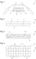
- FIG. 1 represents an electronic device 1, here a watch, comprising a case 2, in which an electronic system 3 is arranged.
- the electronic system 3 comprises, for example, an electronic quartz motor, and digital or analog display means with needles which are controlled by the electronic motor.
- the case 2 of the watch comprises a housing 14 for a battery 4 making it possible to supply the electronic system 3.
- the watch comprises an endothermic protection module 10 configured to be triggered in the event of thermal runaway of the battery 4 in order to absorb the heat.
- the protection module 10 is arranged in the housing between the battery 4 and the bottom 5 of the case 2.
- the protection module being for example arranged outside the box, against a wall corresponding to the position of the battery inside the box.
- the module In the case of a watch, the module is placed between the bottom of the case and the skin of the wearer of the watch. Thus, the wearer of the watch is protected by the module in case of runaway.
- the protection module can be placed against the battery, opposite the skin of the user for reasons of size. The heat flow is then deflected in the opposite direction to that of the user, limiting the temperature in contact with the skin.
- the module can also be arranged on an already existing electronic device, for example a mobile telephone.
- the module is fixed on the external face of the box corresponding to the position of the battery inside the box.
- Different kinds of fixing means are possible to attach the module to the face of the case, such as screws, glue resistant to high temperatures, or magnets.
- the endothermic protection module 10 is configured to trigger automatically from a threshold temperature, in order to absorb at least part of the heat given off by the battery.
- the module 10 comprises two products 7, 8, which are separated before the triggering of the module 10, and which are mixed when it is triggered.
- the mixture of the two products 7, 8 causes an endothermic chemical reaction, which makes it possible to absorb the heat given off by the battery 4.
- the products 7, 8 mix automatically from a predetermined temperature acting as a threshold value.
- the trigger temperature is above 80°C, or even above 100°C.
- the first product 7 is for example ammonium nitrate and the second product 8 is water.
- the mixture of the two products 7, 8 causes an endothermic reaction.
- the mixture of the products 7, 8 of each couple produces an endothermic reaction, which absorbs the heat given off by the battery.
- the two products 7, 8 are arranged in an enclosure 6 disposed in the housing 14.
- the two products 7, 8 are separated by a wall 9 configured to prevent mixing of the products 7, 8. It may for example be sealed.
- the wall 9 is degradable from a predetermined temperature.
- the module 10 is triggered automatically, when the temperature given off by the battery 4 exceeds the threshold value.
- the wall 9 is a membrane which disintegrates beyond said determined temperature.
- the membrane is for example a metal alloy with a low melting point, such as a Bismuth alloy, of the MCP96 ® type, which has a melting point of 100°C.
- the melting temperature serves as the threshold value. Beyond the melting point, the membrane melts and the two products can mix.
- alloys such as Indium-Titanium Nitride eutectic alloy, Lead-Bismuth-Tin alloy of Rose metal type, Lead-Bismuth alloy, Bismuth-Titanium Nitride eutectic alloy, Titanium, a eutectic Bismuth-Indium alloy.
- These alloys have a different melting temperature, 117°C for the Indium-Titanium Nitride eutectic alloy, 95°C for the Lead-Bismuth-Tin alloy of the Rose metal type, 125°C for the Lead-Bismuth alloy, 138°C for the Bismuth-Titanium Nitride eutectic alloy, 109°C for the Bismuth-Indium eutectic alloy.
- an alloy with a specific melting temperature is chosen.
- the wall has disintegrated, so that the two products 7, 8 mix to produce the endothermic reaction.
- the wall 9 can also comprise, preferably entirely, a polymer material, such as acrylonitrile butadiene styrene of the ABS type, low density polyethylene of the LDPE type, or polyvinyl chloride of the PVC type.
- a polymer material such as acrylonitrile butadiene styrene of the ABS type, low density polyethylene of the LDPE type, or polyvinyl chloride of the PVC type.
- Acrylonitrile butadiene styrene has a melting temperature of 130°C, low density polyethylene and polyvinyl chloride having a melting temperature of 100°C.
- the enclosure 13 comprises a plurality of compartments 11, 12, each compartment 11, 12 comprising one of the two products 7, 8.
- the compartments 11, 12 are smaller than in the first embodiment.
- the compartments 11, 12 alternately comprise each product 7, 8.
- Each compartment 11, 12 is closed by a wall 9 degradable at a predefined temperature.
- the walls 9 are of the same type as that of the first variant.
- the walls of each compartment degrade, so that the two products can mix. Thanks to this configuration, the mixing of the products is carried out better.
- the module according to this embodiment is more efficient, because the reaction between the products is very rapid.
Landscapes
- Engineering & Computer Science (AREA)
- Physics & Mathematics (AREA)
- General Physics & Mathematics (AREA)
- Chemical & Material Sciences (AREA)
- Chemical Kinetics & Catalysis (AREA)
- Computer Hardware Design (AREA)
- Theoretical Computer Science (AREA)
- Power Engineering (AREA)
- Microelectronics & Electronic Packaging (AREA)
- General Chemical & Material Sciences (AREA)
- Electrochemistry (AREA)
- Manufacturing & Machinery (AREA)
- Thermal Sciences (AREA)
- Human Computer Interaction (AREA)
- General Engineering & Computer Science (AREA)
- Combustion & Propulsion (AREA)
- Materials Engineering (AREA)
- Organic Chemistry (AREA)
- Battery Mounting, Suspending (AREA)
- Electric Clocks (AREA)
- Secondary Cells (AREA)
- Electromechanical Clocks (AREA)
Abstract
Description
- L'invention concerne le domaine des dispositifs électroniques munis de batteries.
- Les batteries des dispositifs électroniques, tels des montres ou des téléphones portables, peuvent subir un emballement thermique d'une façon non prédictible, par exemple suite à un choc, des températures extrêmes, voire même des défauts de production. Malgré une production de haute qualité, il est commun d'estimer toujours un risque de un à dix pour un million de faire face à un emballement thermique sur la vie d'une batterie. Malgré l'utilisation de batteries provenant de productions ayant de hauts standards sur le contrôle qualité, il arrive de voir des attaques en justices contre certains fabricants de dispositifs électroniques, par des utilisateurs ayant eu le poignet brulé par un produit défectueux.
- Dans cette situation d'emballement thermique, toute l'énergie chimique de la batterie est dégagée en quelques secondes sous forme d'énergie thermique. Par exemple, une batterie Lithium Ion CR2032 de 100mAh peut monter à plus de 100°C en moins d'une minute.
- Lorsque le dispositif électronique est en contact avec la peau, par exemple pour des produits horlogers, la température du boitier peut augmenter au-delà du seuil de brûlure et blesser le porteur de la montre.
- L'invention a pour but de remédier aux inconvénients précités, et vise à fournir un dispositif électronique muni d'une batterie, qui protège le porteur du dispositif électronique du risque de brûlure en cas d'emballement thermique de la batterie.
- A cette fin, l'invention se rapporte à un dispositif électronique, notamment une montre électronique, comprenant un boîtier et un système électronique agencé dans le boîtier, le boîtier étant muni d'un logement pour une batterie permettant d'alimenter le système électronique en énergie.
- Le dispositif électronique est remarquable en ce qu'il comprend un module de protection endothermique autonome configuré pour se déclencher automatiquement en cas d'emballement thermique de la batterie afin d'absorber la chaleur.
- Pour les occasions où une batterie dysfonctionne en chauffant très fort, le module de protection se déclenche et absorbe au moins en partie la chaleur produite par la batterie. Ainsi, l'utilisateur du dispositif électronique est protégé contre le risque de brûlure.
- Grâce à l'invention, on évite d'avoir recours à des protections thermiques complexes à mettre en œuvre, du point de vue de l'agencement interne dans le dispositif électronique. De plus, le module peut être adapté sur des dispositifs électroniques existants.
- Selon une forme de réalisation particulière de l'invention, le module se déclenche automatiquement à partir d'une température seuil.
- Selon une forme de réalisation particulière de l'invention, le module de protection thermique comprend deux produits séparés avant le déclenchement, et qui se mélangent après le déclenchement automatique.
- Selon une forme de réalisation particulière de l'invention, les deux produits sont séparés par une paroi avant le déclenchement, la paroi étant dégradable au-delà d'une température seuil.
- Selon une forme de réalisation particulière de l'invention, la paroi comprend un alliage métallique à faible température de fusion.
- Selon une forme de réalisation particulière de l'invention, les deux produits sont agencés dans une enceinte disposée dans le logement.
- Selon une forme de réalisation particulière de l'invention, l'enceinte comporte une pluralité de compartiments, chaque compartiment comportant l'un des deux produits.
- Selon une forme de réalisation particulière de l'invention, les compartiments comprennent alternativement chaque produit.
- Selon une forme de réalisation particulière de l'invention, les compartiments sont fermés par une paroi dégradable au-delà de la température seuil.
- Selon une forme de réalisation particulière de l'invention, le premier et le deuxième produit à mélanger sont à choisir parmi les couples suivants :
- nitrate d'ammonium et eau,
- chlorure de potassium et eau,
- carbonate de sodium et acide éthanoïque,
- chlorure de thionyle et sulfate de cobalt heptahydraté,
- cristaux d'hydroxyde de Baryum octohydraté et chlorure d'ammonium sec.
- Selon une forme de réalisation particulière de l'invention, la paroi comprend, de préférence en totalité, un matériau à choisir dans la liste suivante : alliage eutectique d'indium-nitrure de Titane, alliage de Plomb-Bismuth-étain de type métal de Rose, alliage de Plomb-Bismuth, alliage eutectique de Bismuth-nitrure de Titane, alliage eutectique de Bismuth-Indium.
- Selon une forme de réalisation particulière de l'invention, la paroi comprend, de préférence en totalité, un matériau polymère, par exemple l'acrylonitrile butadiène styrène de type ABS, le polyéthylène basse densité de type PEBD, ou le polychlorure de vinyle de type PVC
- Selon une forme de réalisation particulière de l'invention, le module de protection endothermique est agencé dans le boitier.
- Selon une forme de réalisation particulière de l'invention, le module de protection endothermique est agencé à l'extérieur du boitier.
- Selon une forme de réalisation particulière de l'invention, la paroi comprend, de préférence en totalité, un alliage métallique à faible température de fusion
- Les buts, avantages et caractéristiques apparaîtront à la lecture de la description détaillée qui va suivre, en référence aux dessins annexés, où :
- la
figure 1 montre une représentation schématique d'un premier mode de réalisation d'une montre électronique munie d'une batterie, et d'un module de protection thermique selon l'invention, - la
figure 2 montre une représentation schématique d'un premier mode de réalisation d'un module de protection thermique avant le déclenchement, - la
figure 3 montre une représentation schématique du premier mode de réalisation du module de protection thermique après le déclenchement, et - la
figure 4 montre une représentation schématique d'un deuxième mode de réalisation d'un module de protection thermique. - La
figure 1 représente un dispositif électronique 1, ici une montre, comprenant un boitier 2, dans lequel est agencé un système électronique 3. Le système électronique 3 comprend, par exemple, un moteur électronique à quartz, et des moyens d'affichage digitaux ou analogiques à aiguilles qui sont commandés par le moteur électronique. Le boitier 2 de la montre comprend un logement 14 pour une batterie 4 permettant d'alimenter le système électronique 3. - Selon l'invention, la montre comprend un module de protection 10 endothermique configuré pour se déclencher en cas d'emballement thermique de la batterie 4 afin absorber la chaleur.
- Dans l'exemple de la
figure 1 , le module de protection 10 est agencé dans le logement entre la batterie 4 et le fond 5 du boitier 2. - D'autres configurations sont possibles, le module de protection étant par exemple agencé à l'extérieur du boitier, contre une paroi correspondant à la position de la batterie à l'intérieur du boitier. Dans le cas d'une montre, le module est disposé entre le fond du boitier et la peau du porteur de la montre. Ainsi, le porteur de la montre est protégé par le module en cas d'emballement.
- Dans une autre configuration, le module de protection peut être disposé contre la batterie, à l'opposé de la peau de l'utilisateur pour des raisons d'encombrement. Le flux de chaleur est alors dévié dans la direction opposée de celle de l'utilisateur, limitant la température au contact de la peau.
- Le module peut aussi être agencé sur un dispositif électronique déjà existant, par exemple un téléphone portable. Le module est fixé sur la face externe du boitier correspondant à la position de la batterie à l'intérieur du boitier. Différentes sortes de moyens de fixation sont possibles pour attacher le module sur la face du boitier, tels que des vis, une colle résistant aux températures élevées, ou des aimants.
- Le module de protection endothermique 10 est configuré pour se déclencher automatiquement à partir d'une température seuil, afin d'absorber au moins en partie la chaleur dégagée par la batterie.
- A cette fin, le module 10 comprend deux produits 7, 8, qui sont séparés avant le déclenchement du module 10, et qui sont mélangés lorsqu'il se déclenche. Le mélange des deux produits 7, 8 provoque une réaction chimique endothermique, qui permet d'absorber la chaleur dégagée par la batterie 4.
- Les produits 7, 8 se mélangent automatiquement à partir d'une température prédéterminée faisant office de valeur seuil. De préférence, la température de déclenchement est au-delà de 80°C, voire au-delà de 100°C.
- Il existe différents types de produits 7, 8 que l'on peut mélanger pour obtenir une réaction endothermique. Cette réaction endothermique permet d'absorber au moins en partie la chaleur dégagée par la batterie. Même si l'énergie n'est absorbée qu'en partie, la température du fond 5 du boitier 2 diminue, de sorte que le porteur de la montre évite une brûlure, et n'a qu'une sensation de forte chaleur.
- Pour obtenir une réaction endothermique, le premier produit 7 est par exemple du nitrate d'ammonium et le deuxième produit 8 est de l'eau. Le mélange des deux produits 7, 8 provoque une réaction endothermique.
- D'autres couples de produits 7, 8 sont possibles, le premier 7 et le deuxième produit 8 à mélanger étant à choisir parmi les couples suivants :
- chlorure de potassium et eau,
- carbonate de sodium et acide éthanoïque,
- chlorure de thionyle et sulfate de cobalt heptahydraté,
- cristaux d'hydroxyde de Baryum octohydraté et chlorure d'ammonium sec.
- Le mélange des produits 7, 8 de chaque couple produit une réaction endothermique, qui absorbe la chaleur dégagée par la batterie.
- Sur la
figure 2 , les deux produits 7, 8 sont agencés dans une enceinte 6 disposée dans le logement 14. Les deux produits 7, 8 sont séparés par une paroi 9 configurée pour éviter le mélange des produits 7, 8. Elle peut par exemple être étanche. - La paroi 9 est dégradable à partir d'une température prédéterminée. Ainsi, en cas d'emballement de la température de la batterie 4, le module 10 se déclenche automatiquement, lorsque la température dégagée par la batterie 4 dépasse la valeur seuil.
- La paroi 9 est une membrane qui se désagrège au-delà de ladite température déterminée. La membrane est par exemple un alliage métallique à faible température de fusion, tel qu'un alliage de Bismuth, de type MCP96®, qui a une température de fusion de 100°C. La température de fusion fait office de valeur seuil. Au-delà de la température de fusion, la membrane fond et les deux produits peuvent se mélanger.
- D'autres alliages sont possibles, tels qu'un alliage eutectique d'indium-nitrure de Titane, un alliage de Plomb-Bismuth-étain de type métal de Rose, un alliage de Plomb-Bismuth, un alliage eutectique de Bismuth-nitrure de Titane, un alliage eutectique de Bismuth-Indium.
- Ces alliages ont une température de fusion différente, 117°C pour l'alliage eutectique d'indium-nitrure de Titane, 95°C pour l'alliage de Plomb-Bismuth-étain de type métal de Rose, 125°C pour l'alliage de Plomb-Bismuth, 138°C pour l'alliage eutectique de Bismuth-nitrure de Titane, 109°C pour l'alliage eutectique de Bismuth-Indium.
- Ainsi, en fonction de la protection que l'on souhaite, on choisit un alliage ayant une température de fusion spécifique.
- Sur la
figure 3 , la paroi s'est désagrégée, de sorte que les deux produits 7, 8 se mélange pour produire la réaction endothermique. - La paroi 9 peut aussi comprendre, de préférence en totalité, un matériau polymère, tel que l'acrylonitrile butadiène styrène de type ABS, le polyéthylène basse densité de type PEBD, ou le polychlorure de vinyle de type PVC. L'acrylonitrile butadiène styrène a une température de fusion de 130°C, le polyéthylène basse densité et le polychlorure de vinyle ayant une température de fusion de 100°C.
- Dans une variante de réalisation du module 20, représentée sur la
figure 4 , l'enceinte 13 comporte une pluralité de compartiments 11, 12, chaque compartiment 11, 12 comportant l'un des deux produits 7, 8. Les compartiments 11, 12 sont de plus petite taille que dans le premier mode de réalisation. De préférence, les compartiments 11, 12 comprennent alternativement chaque produit 7, 8. - Chaque compartiment 11, 12 est fermé par une paroi 9 dégradable à une température prédéfinie. Les parois 9 sont du même type que celle de la première variante.
- Ainsi, au-delà de la valeur seuil de température, les parois de chaque compartiment se dégradent, de sorte que les deux produits peuvent se mélanger. Grâce à cette configuration, le mélange des produits s'effectue mieux. Le module selon ce mode de réalisation est plus performant, car la réaction entre les produits est très rapide.
- Bien entendu, la présente invention ne se limite pas aux exemples illustrés, mais elle est susceptible de diverses variantes et modifications qui apparaîtront à l'homme de l'art. D'autres applications sont possibles, en dehors de l'horlogerie, tels les téléphones portables, les ordinateurs portables, ou tout autre objet électronique portable.
Claims (14)
- Dispositif électronique (1), notamment une montre électronique, comprenant un boîtier (2) et un système électronique (3) agencé dans le boîtier (2), le boîtier (2) étant muni d'un logement (14) pour une batterie (5) permettant d'alimenter le système électronique (3) en énergie, caractérisé en ce qu'il comprend un module de protection (10) endothermique autonome configuré pour se déclencher automatiquement en cas d'emballement thermique de la batterie (5) afin d'absorber la chaleur.
- Dispositif électronique selon la revendication 1, caractérisé en ce que le module (10) se déclenche automatiquement à partir d'une température seuil.
- Dispositif électronique selon la revendication 2, caractérisé en ce que le module de protection (10) comprend deux produits (7, 8) séparés avant le déclenchement, et qui se mélangent après le déclenchement automatique.
- Dispositif électronique selon la revendication 3, caractérisé en ce que les deux produits (7, 8) sont agencés dans une enceinte (6) disposée dans le boitier (2).
- Dispositif électronique selon la revendication 3 ou 4, caractérisé en ce que les deux produits (7, 8) sont séparés par une paroi (9) avant le déclenchement, la paroi (9) étant dégradable au-delà de la température seuil.
- Dispositif électronique selon la revendication 5, caractérisé en ce que l'enceinte (6) comporte une pluralité de compartiments (12, 13), chaque compartiment (12, 13) comportant l'un des deux produits (7, 8).
- Dispositif électronique selon la revendication 6, caractérisé en ce que les compartiments (12, 13) comprennent alternativement chaque produit (7, 8).
- Dispositif électronique selon la revendication 6 ou 7, caractérisé en ce que les compartiments (12, 13) sont fermés par une paroi (9) dégradable au-delà de la température seuil.
- Dispositif électronique selon l'une, quelconque, des revendications 4 à 8, caractérisé en ce que la paroi (9) comprend, de préférence en totalité, un alliage métallique à faible température de fusion.
- Dispositif électronique selon la revendication 9, caractérisé en ce que la paroi (9) comprend, de préférence en totalité, un matériau à choisir dans la liste suivante : un alliage eutectique d'indium-nitrure de Titane, un alliage de Plomb-Bismuth-étain de type métal de Rose, un alliage de Plomb-Bismuth, un alliage eutectique de Bismuth-nitrure de Titane, un alliage eutectique de Bismuth-Indium.
- Dispositif électronique selon la revendication 8, caractérisé en ce que la paroi comprend, de préférence en totalité, un matériau polymère, par exemple l'acrylonitrile butadiène styrène de type ABS, le polyéthylène basse densité de type PEBD, ou le polychlorure de vinyle de type PVC.
- Dispositif électronique selon l'une, quelconque, des revendications 3 à 8, caractérisé en ce que le premier (7) et le deuxième (8) produit à mélanger sont à choisir parmi les couples suivants :- nitrate d'ammonium et eau,- chlorure de potassium et eau,- carbonate de sodium et acide éthanoïque,- chlorure de thionyle et sulfate de cobalt heptahydraté,- cristaux d'hydroxyde de Baryum octohydraté et chlorure d'ammonium sec.
- Dispositif électronique selon l'une, quelconque, des revendications précédentes, caractérisé en ce que le module de protection (10) endothermique est agencé dans le boitier (2).
- Dispositif électronique selon l'une, quelconque, des revendications précédentes, caractérisé en ce que le module de protection endothermique est agencé à l'extérieur du boitier.
Priority Applications (8)
| Application Number | Priority Date | Filing Date | Title |
|---|---|---|---|
| FIEP21208584.9T FI4180883T3 (fi) | 2021-11-16 | 2021-11-16 | Akun ja suojausmoduulin käsittävä elektroninen laite |
| EP21208584.9A EP4180883B1 (fr) | 2021-11-16 | 2021-11-16 | Dispositif électronique comprenant une batterie et un module de protection |
| US18/049,455 US20230155204A1 (en) | 2021-11-16 | 2022-10-25 | Electronic device comprising a battery and a protection module |
| JP2022175304A JP7543370B2 (ja) | 2021-11-16 | 2022-11-01 | 電池と保護モジュールを備える電子デバイス |
| KR1020220150894A KR20230071741A (ko) | 2021-11-16 | 2022-11-11 | 배터리 및 보호 모듈을 포함하는 전자 디바이스 |
| CN202223043360.9U CN219738020U (zh) | 2021-11-16 | 2022-11-16 | 包括电池和保护模块的电子设备 |
| CN202211433727.XA CN116136658A (zh) | 2021-11-16 | 2022-11-16 | 包括电池和保护模块的电子设备 |
| KR1020250096962A KR20250114475A (ko) | 2021-11-16 | 2025-07-17 | 배터리 및 보호 모듈을 포함하는 전자 디바이스 |
Applications Claiming Priority (1)
| Application Number | Priority Date | Filing Date | Title |
|---|---|---|---|
| EP21208584.9A EP4180883B1 (fr) | 2021-11-16 | 2021-11-16 | Dispositif électronique comprenant une batterie et un module de protection |
Publications (2)
| Publication Number | Publication Date |
|---|---|
| EP4180883A1 true EP4180883A1 (fr) | 2023-05-17 |
| EP4180883B1 EP4180883B1 (fr) | 2025-07-30 |
Family
ID=78676387
Family Applications (1)
| Application Number | Title | Priority Date | Filing Date |
|---|---|---|---|
| EP21208584.9A Active EP4180883B1 (fr) | 2021-11-16 | 2021-11-16 | Dispositif électronique comprenant une batterie et un module de protection |
Country Status (6)
| Country | Link |
|---|---|
| US (1) | US20230155204A1 (fr) |
| EP (1) | EP4180883B1 (fr) |
| JP (1) | JP7543370B2 (fr) |
| KR (2) | KR20230071741A (fr) |
| CN (2) | CN116136658A (fr) |
| FI (1) | FI4180883T3 (fr) |
Families Citing this family (2)
| Publication number | Priority date | Publication date | Assignee | Title |
|---|---|---|---|---|
| FI4180883T3 (fi) * | 2021-11-16 | 2025-10-15 | Eta Sa Mft Horlogere Suisse | Akun ja suojausmoduulin käsittävä elektroninen laite |
| CN116565440B (zh) * | 2023-07-11 | 2023-11-03 | 宁德时代新能源科技股份有限公司 | 电池及用电设备 |
Citations (2)
| Publication number | Priority date | Publication date | Assignee | Title |
|---|---|---|---|---|
| CN211296765U (zh) * | 2020-03-09 | 2020-08-18 | Oppo广东移动通信有限公司 | 一种电子设备的保护壳 |
| CN112255905A (zh) * | 2020-10-22 | 2021-01-22 | 维沃移动通信有限公司 | 穿戴设备、控制方法、装置及电子设备 |
Family Cites Families (13)
| Publication number | Priority date | Publication date | Assignee | Title |
|---|---|---|---|---|
| JP4297698B2 (ja) * | 2003-02-26 | 2009-07-15 | 三洋電機株式会社 | 電池パック及び非水電解液二次電池を電源とする電子機器 |
| JP2009082810A (ja) * | 2007-09-28 | 2009-04-23 | Casio Comput Co Ltd | 断熱装置及び燃料電池システム並びに断熱容器の冷却方法 |
| US8586233B2 (en) * | 2008-09-22 | 2013-11-19 | Panasonic Corporation | Portable electronic device |
| KR101179364B1 (ko) * | 2008-09-22 | 2012-09-03 | 파나소닉 주식회사 | 휴대전자기기 |
| JP6066217B2 (ja) * | 2011-04-13 | 2017-01-25 | クライオセラピューティクス ゲーエムベーハー | システムおよびクライオエネルギーを供給するシステムを動作させる方法 |
| US9226428B2 (en) * | 2012-06-28 | 2015-12-29 | Intel Corporation | High heat capacity electronic components and methods for fabricating |
| US9608686B1 (en) * | 2015-12-03 | 2017-03-28 | Honeywell Federal Manufacturing & Technologies, Llc | Case for cooling an electronic device via an endothermic reaction |
| US10665909B2 (en) * | 2017-07-17 | 2020-05-26 | International Business Machines Corporation | Battery thermal run-away and combustion prevention system |
| CN209731895U (zh) * | 2019-01-16 | 2019-12-03 | 广东小天才科技有限公司 | 一种具有散热功能的智能主机及智能手表 |
| JP2021118162A (ja) * | 2020-01-29 | 2021-08-10 | 積水化学工業株式会社 | 耐火樹脂組成物、耐火材、耐火積層体、バッテリー、背面カバー材及び電子機器 |
| CN212011198U (zh) * | 2020-06-17 | 2020-11-24 | 谭清 | 一种穿戴设备局部隔热的散热片 |
| CN113178907A (zh) * | 2021-04-21 | 2021-07-27 | 深圳市驰普科达科技有限公司 | 一种工业电池用智能充电设备及其充电方法 |
| FI4180883T3 (fi) * | 2021-11-16 | 2025-10-15 | Eta Sa Mft Horlogere Suisse | Akun ja suojausmoduulin käsittävä elektroninen laite |
-
2021
- 2021-11-16 FI FIEP21208584.9T patent/FI4180883T3/fi active
- 2021-11-16 EP EP21208584.9A patent/EP4180883B1/fr active Active
-
2022
- 2022-10-25 US US18/049,455 patent/US20230155204A1/en active Pending
- 2022-11-01 JP JP2022175304A patent/JP7543370B2/ja active Active
- 2022-11-11 KR KR1020220150894A patent/KR20230071741A/ko not_active Ceased
- 2022-11-16 CN CN202211433727.XA patent/CN116136658A/zh active Pending
- 2022-11-16 CN CN202223043360.9U patent/CN219738020U/zh active Active
-
2025
- 2025-07-17 KR KR1020250096962A patent/KR20250114475A/ko active Pending
Patent Citations (2)
| Publication number | Priority date | Publication date | Assignee | Title |
|---|---|---|---|---|
| CN211296765U (zh) * | 2020-03-09 | 2020-08-18 | Oppo广东移动通信有限公司 | 一种电子设备的保护壳 |
| CN112255905A (zh) * | 2020-10-22 | 2021-01-22 | 维沃移动通信有限公司 | 穿戴设备、控制方法、装置及电子设备 |
Also Published As
| Publication number | Publication date |
|---|---|
| EP4180883B1 (fr) | 2025-07-30 |
| FI4180883T3 (fi) | 2025-10-15 |
| JP2023073981A (ja) | 2023-05-26 |
| CN116136658A (zh) | 2023-05-19 |
| US20230155204A1 (en) | 2023-05-18 |
| JP7543370B2 (ja) | 2024-09-02 |
| KR20230071741A (ko) | 2023-05-23 |
| KR20250114475A (ko) | 2025-07-29 |
| CN219738020U (zh) | 2023-09-22 |
Similar Documents
| Publication | Publication Date | Title |
|---|---|---|
| EP4180883B1 (fr) | Dispositif électronique comprenant une batterie et un module de protection | |
| JP2020530181A (ja) | バッテリーモジュール | |
| WO2006026233A3 (fr) | Batterie contenant li/fes2 a faible temperature | |
| SI1484088T1 (sl) | Prenosni aerosolni gasilni aparat | |
| FR2775124A1 (fr) | Accumulateur au lithium, composition cathodique et cathode pour accumulateur au lithium | |
| CN101981726A (zh) | 具有至少一个布置在一个外壳结构中的电化学电池的电池组 | |
| CH719149A2 (fr) | Dispositif électronique comprenant une batterie et un module de protection. | |
| JP2013178909A (ja) | 二次電池、それを用いた組電池、および二次電池用シート状蓄熱部材 | |
| US20170203135A1 (en) | Cellular telephone fire suppression packet | |
| EP1550733A4 (fr) | Element de fusible thermique, fusible thermique et batterie comprenant celui-ci | |
| US9128684B2 (en) | Tablet case | |
| EP3987598A1 (fr) | Batterie | |
| FR2775833A1 (fr) | Accumulateur au lithium et sa composition cathodique | |
| EP1763098A4 (fr) | Batterie de substance à action liquide | |
| CN211404542U (zh) | 一种电池帽盖 | |
| CN107275525B (zh) | 一种终端保护壳 | |
| CN113134197A (zh) | 灭火贴 | |
| CN202259558U (zh) | 一种铝壳圆柱形锂离子电池 | |
| HK40092697A (zh) | 包括电池和保护模块的电子设备 | |
| EP3524905B1 (fr) | Dispositif de refroidissement à réaction chimique endothermique | |
| EP3120292B1 (fr) | Dispositif autonome en énergie doté de moyens d'autodestruction | |
| CN205355140U (zh) | 二次电池 | |
| CN207785701U (zh) | 一种温度及压力释放的灭火装置 | |
| CN218420738U (zh) | 一种储能电池模组消防模块 | |
| JP2004186097A5 (fr) |
Legal Events
| Date | Code | Title | Description |
|---|---|---|---|
| PUAI | Public reference made under article 153(3) epc to a published international application that has entered the european phase |
Free format text: ORIGINAL CODE: 0009012 |
|
| STAA | Information on the status of an ep patent application or granted ep patent |
Free format text: STATUS: THE APPLICATION HAS BEEN PUBLISHED |
|
| AK | Designated contracting states |
Kind code of ref document: A1 Designated state(s): AL AT BE BG CH CY CZ DE DK EE ES FI FR GB GR HR HU IE IS IT LI LT LU LV MC MK MT NL NO PL PT RO RS SE SI SK SM TR |
|
| P01 | Opt-out of the competence of the unified patent court (upc) registered |
Effective date: 20230701 |
|
| STAA | Information on the status of an ep patent application or granted ep patent |
Free format text: STATUS: REQUEST FOR EXAMINATION WAS MADE |
|
| 17P | Request for examination filed |
Effective date: 20231116 |
|
| RBV | Designated contracting states (corrected) |
Designated state(s): AL AT BE BG CH CY CZ DE DK EE ES FI FR GB GR HR HU IE IS IT LI LT LU LV MC MK MT NL NO PL PT RO RS SE SI SK SM TR |
|
| GRAP | Despatch of communication of intention to grant a patent |
Free format text: ORIGINAL CODE: EPIDOSNIGR1 |
|
| STAA | Information on the status of an ep patent application or granted ep patent |
Free format text: STATUS: GRANT OF PATENT IS INTENDED |
|
| INTG | Intention to grant announced |
Effective date: 20250411 |
|
| GRAS | Grant fee paid |
Free format text: ORIGINAL CODE: EPIDOSNIGR3 |
|
| GRAA | (expected) grant |
Free format text: ORIGINAL CODE: 0009210 |
|
| STAA | Information on the status of an ep patent application or granted ep patent |
Free format text: STATUS: THE PATENT HAS BEEN GRANTED |
|
| AK | Designated contracting states |
Kind code of ref document: B1 Designated state(s): AL AT BE BG CH CY CZ DE DK EE ES FI FR GB GR HR HU IE IS IT LI LT LU LV MC MK MT NL NO PL PT RO RS SE SI SK SM TR |
|
| REG | Reference to a national code |
Ref country code: GB Ref legal event code: FG4D Free format text: NOT ENGLISH |
|
| REG | Reference to a national code |
Ref country code: CH Ref legal event code: EP |
|
| REG | Reference to a national code |
Ref country code: DE Ref legal event code: R096 Ref document number: 602021034996 Country of ref document: DE |
|
| REG | Reference to a national code |
Ref country code: IE Ref legal event code: FG4D Free format text: LANGUAGE OF EP DOCUMENT: FRENCH |
|
| REG | Reference to a national code |
Ref country code: FI Ref legal event code: FGE |
|
| REG | Reference to a national code |
Ref country code: CH Ref legal event code: U11 Free format text: ST27 STATUS EVENT CODE: U-0-0-U10-U11 (AS PROVIDED BY THE NATIONAL OFFICE) Effective date: 20251201 |
|
| REG | Reference to a national code |
Ref country code: NL Ref legal event code: MP Effective date: 20250730 |
|
| REG | Reference to a national code |
Ref country code: AT Ref legal event code: MK05 Ref document number: 1819610 Country of ref document: AT Kind code of ref document: T Effective date: 20250730 |
|
| PG25 | Lapsed in a contracting state [announced via postgrant information from national office to epo] |
Ref country code: PT Free format text: LAPSE BECAUSE OF FAILURE TO SUBMIT A TRANSLATION OF THE DESCRIPTION OR TO PAY THE FEE WITHIN THE PRESCRIBED TIME-LIMIT Effective date: 20251202 |
|
| PG25 | Lapsed in a contracting state [announced via postgrant information from national office to epo] |
Ref country code: IS Free format text: LAPSE BECAUSE OF FAILURE TO SUBMIT A TRANSLATION OF THE DESCRIPTION OR TO PAY THE FEE WITHIN THE PRESCRIBED TIME-LIMIT Effective date: 20251130 |
|
| PGFP | Annual fee paid to national office [announced via postgrant information from national office to epo] |
Ref country code: DE Payment date: 20251022 Year of fee payment: 5 |
|
| PGFP | Annual fee paid to national office [announced via postgrant information from national office to epo] |
Ref country code: GB Payment date: 20251022 Year of fee payment: 5 |
|
| PG25 | Lapsed in a contracting state [announced via postgrant information from national office to epo] |
Ref country code: NO Free format text: LAPSE BECAUSE OF FAILURE TO SUBMIT A TRANSLATION OF THE DESCRIPTION OR TO PAY THE FEE WITHIN THE PRESCRIBED TIME-LIMIT Effective date: 20251030 |
|
| REG | Reference to a national code |
Ref country code: LT Ref legal event code: MG9D |
|
| PG25 | Lapsed in a contracting state [announced via postgrant information from national office to epo] |
Ref country code: AT Free format text: LAPSE BECAUSE OF FAILURE TO SUBMIT A TRANSLATION OF THE DESCRIPTION OR TO PAY THE FEE WITHIN THE PRESCRIBED TIME-LIMIT Effective date: 20250730 |
|
| PGFP | Annual fee paid to national office [announced via postgrant information from national office to epo] |
Ref country code: FI Payment date: 20251022 Year of fee payment: 5 |
|
| PG25 | Lapsed in a contracting state [announced via postgrant information from national office to epo] |
Ref country code: NL Free format text: LAPSE BECAUSE OF FAILURE TO SUBMIT A TRANSLATION OF THE DESCRIPTION OR TO PAY THE FEE WITHIN THE PRESCRIBED TIME-LIMIT Effective date: 20250730 Ref country code: HR Free format text: LAPSE BECAUSE OF FAILURE TO SUBMIT A TRANSLATION OF THE DESCRIPTION OR TO PAY THE FEE WITHIN THE PRESCRIBED TIME-LIMIT Effective date: 20250730 |
|
| PGFP | Annual fee paid to national office [announced via postgrant information from national office to epo] |
Ref country code: FR Payment date: 20251023 Year of fee payment: 5 |
|
| PG25 | Lapsed in a contracting state [announced via postgrant information from national office to epo] |
Ref country code: GR Free format text: LAPSE BECAUSE OF FAILURE TO SUBMIT A TRANSLATION OF THE DESCRIPTION OR TO PAY THE FEE WITHIN THE PRESCRIBED TIME-LIMIT Effective date: 20251031 |
|
| PGFP | Annual fee paid to national office [announced via postgrant information from national office to epo] |
Ref country code: CH Payment date: 20251201 Year of fee payment: 5 |
|
| PG25 | Lapsed in a contracting state [announced via postgrant information from national office to epo] |
Ref country code: SE Free format text: LAPSE BECAUSE OF FAILURE TO SUBMIT A TRANSLATION OF THE DESCRIPTION OR TO PAY THE FEE WITHIN THE PRESCRIBED TIME-LIMIT Effective date: 20250730 |
|
| PG25 | Lapsed in a contracting state [announced via postgrant information from national office to epo] |
Ref country code: LV Free format text: LAPSE BECAUSE OF FAILURE TO SUBMIT A TRANSLATION OF THE DESCRIPTION OR TO PAY THE FEE WITHIN THE PRESCRIBED TIME-LIMIT Effective date: 20250730 |
|
| PG25 | Lapsed in a contracting state [announced via postgrant information from national office to epo] |
Ref country code: BG Free format text: LAPSE BECAUSE OF FAILURE TO SUBMIT A TRANSLATION OF THE DESCRIPTION OR TO PAY THE FEE WITHIN THE PRESCRIBED TIME-LIMIT Effective date: 20250730 Ref country code: PL Free format text: LAPSE BECAUSE OF FAILURE TO SUBMIT A TRANSLATION OF THE DESCRIPTION OR TO PAY THE FEE WITHIN THE PRESCRIBED TIME-LIMIT Effective date: 20250730 |
|
| PG25 | Lapsed in a contracting state [announced via postgrant information from national office to epo] |
Ref country code: RS Free format text: LAPSE BECAUSE OF FAILURE TO SUBMIT A TRANSLATION OF THE DESCRIPTION OR TO PAY THE FEE WITHIN THE PRESCRIBED TIME-LIMIT Effective date: 20251030 |
|
| PG25 | Lapsed in a contracting state [announced via postgrant information from national office to epo] |
Ref country code: ES Free format text: LAPSE BECAUSE OF FAILURE TO SUBMIT A TRANSLATION OF THE DESCRIPTION OR TO PAY THE FEE WITHIN THE PRESCRIBED TIME-LIMIT Effective date: 20250730 |
|
| PG25 | Lapsed in a contracting state [announced via postgrant information from national office to epo] |
Ref country code: RO Free format text: LAPSE BECAUSE OF FAILURE TO SUBMIT A TRANSLATION OF THE DESCRIPTION OR TO PAY THE FEE WITHIN THE PRESCRIBED TIME-LIMIT Effective date: 20250730 |
|
| PG25 | Lapsed in a contracting state [announced via postgrant information from national office to epo] |
Ref country code: SM Free format text: LAPSE BECAUSE OF FAILURE TO SUBMIT A TRANSLATION OF THE DESCRIPTION OR TO PAY THE FEE WITHIN THE PRESCRIBED TIME-LIMIT Effective date: 20250730 |
|
| PG25 | Lapsed in a contracting state [announced via postgrant information from national office to epo] |
Ref country code: DK Free format text: LAPSE BECAUSE OF FAILURE TO SUBMIT A TRANSLATION OF THE DESCRIPTION OR TO PAY THE FEE WITHIN THE PRESCRIBED TIME-LIMIT Effective date: 20250730 |
|
| PG25 | Lapsed in a contracting state [announced via postgrant information from national office to epo] |
Ref country code: IT Free format text: LAPSE BECAUSE OF FAILURE TO SUBMIT A TRANSLATION OF THE DESCRIPTION OR TO PAY THE FEE WITHIN THE PRESCRIBED TIME-LIMIT Effective date: 20250730 |
|
| PG25 | Lapsed in a contracting state [announced via postgrant information from national office to epo] |
Ref country code: CZ Free format text: LAPSE BECAUSE OF FAILURE TO SUBMIT A TRANSLATION OF THE DESCRIPTION OR TO PAY THE FEE WITHIN THE PRESCRIBED TIME-LIMIT Effective date: 20250730 |
|
| PG25 | Lapsed in a contracting state [announced via postgrant information from national office to epo] |
Ref country code: SK Free format text: LAPSE BECAUSE OF FAILURE TO SUBMIT A TRANSLATION OF THE DESCRIPTION OR TO PAY THE FEE WITHIN THE PRESCRIBED TIME-LIMIT Effective date: 20250730 Ref country code: EE Free format text: LAPSE BECAUSE OF FAILURE TO SUBMIT A TRANSLATION OF THE DESCRIPTION OR TO PAY THE FEE WITHIN THE PRESCRIBED TIME-LIMIT Effective date: 20250730 |