EP4180657B1 - Bestimmung der position eines windturbinengenerators - Google Patents
Bestimmung der position eines windturbinengenerators Download PDFInfo
- Publication number
- EP4180657B1 EP4180657B1 EP22207182.1A EP22207182A EP4180657B1 EP 4180657 B1 EP4180657 B1 EP 4180657B1 EP 22207182 A EP22207182 A EP 22207182A EP 4180657 B1 EP4180657 B1 EP 4180657B1
- Authority
- EP
- European Patent Office
- Prior art keywords
- signal
- component
- speed
- wind turbine
- determining
- Prior art date
- Legal status (The legal status is an assumption and is not a legal conclusion. Google has not performed a legal analysis and makes no representation as to the accuracy of the status listed.)
- Active
Links
Images


Classifications
-
- G—PHYSICS
- G01—MEASURING; TESTING
- G01D—MEASURING NOT SPECIALLY ADAPTED FOR A SPECIFIC VARIABLE; ARRANGEMENTS FOR MEASURING TWO OR MORE VARIABLES NOT COVERED IN A SINGLE OTHER SUBCLASS; TARIFF METERING APPARATUS; MEASURING OR TESTING NOT OTHERWISE PROVIDED FOR
- G01D5/00—Mechanical means for transferring the output of a sensing member; Means for converting the output of a sensing member to another variable where the form or nature of the sensing member does not constrain the means for converting; Transducers not specially adapted for a specific variable
- G01D5/12—Mechanical means for transferring the output of a sensing member; Means for converting the output of a sensing member to another variable where the form or nature of the sensing member does not constrain the means for converting; Transducers not specially adapted for a specific variable using electric or magnetic means
- G01D5/244—Mechanical means for transferring the output of a sensing member; Means for converting the output of a sensing member to another variable where the form or nature of the sensing member does not constrain the means for converting; Transducers not specially adapted for a specific variable using electric or magnetic means influencing characteristics of pulses or pulse trains; generating pulses or pulse trains
- G01D5/24471—Error correction
- G01D5/2448—Correction of gain, threshold, offset or phase control
-
- F—MECHANICAL ENGINEERING; LIGHTING; HEATING; WEAPONS; BLASTING
- F03—MACHINES OR ENGINES FOR LIQUIDS; WIND, SPRING, OR WEIGHT MOTORS; PRODUCING MECHANICAL POWER OR A REACTIVE PROPULSIVE THRUST, NOT OTHERWISE PROVIDED FOR
- F03D—WIND MOTORS
- F03D13/00—Assembly, mounting or commissioning of wind motors; Arrangements specially adapted for transporting wind motor components
- F03D13/20—Arrangements for mounting or supporting wind motors; Masts or towers for wind motors
-
- F—MECHANICAL ENGINEERING; LIGHTING; HEATING; WEAPONS; BLASTING
- F03—MACHINES OR ENGINES FOR LIQUIDS; WIND, SPRING, OR WEIGHT MOTORS; PRODUCING MECHANICAL POWER OR A REACTIVE PROPULSIVE THRUST, NOT OTHERWISE PROVIDED FOR
- F03D—WIND MOTORS
- F03D17/00—Monitoring or testing of wind motors, e.g. diagnostics
-
- F—MECHANICAL ENGINEERING; LIGHTING; HEATING; WEAPONS; BLASTING
- F03—MACHINES OR ENGINES FOR LIQUIDS; WIND, SPRING, OR WEIGHT MOTORS; PRODUCING MECHANICAL POWER OR A REACTIVE PROPULSIVE THRUST, NOT OTHERWISE PROVIDED FOR
- F03D—WIND MOTORS
- F03D7/00—Controlling wind motors
- F03D7/02—Controlling wind motors the wind motors having rotation axis substantially parallel to the air flow entering the rotor
- F03D7/04—Automatic control; Regulation
- F03D7/042—Automatic control; Regulation by means of an electrical or electronic controller
-
- G—PHYSICS
- G05—CONTROLLING; REGULATING
- G05D—SYSTEMS FOR CONTROLLING OR REGULATING NON-ELECTRIC VARIABLES
- G05D3/00—Control of position or direction
- G05D3/12—Control of position or direction using feedback
-
- H—ELECTRICITY
- H02—GENERATION; CONVERSION OR DISTRIBUTION OF ELECTRIC POWER
- H02P—CONTROL OR REGULATION OF ELECTRIC MOTORS, ELECTRIC GENERATORS OR DYNAMO-ELECTRIC CONVERTERS; CONTROLLING TRANSFORMERS, REACTORS OR CHOKE COILS
- H02P6/00—Arrangements for controlling synchronous motors or other dynamo-electric motors using electronic commutation dependent on the rotor position; Electronic commutators therefor
- H02P6/14—Electronic commutators
- H02P6/16—Circuit arrangements for detecting position
-
- F—MECHANICAL ENGINEERING; LIGHTING; HEATING; WEAPONS; BLASTING
- F05—INDEXING SCHEMES RELATING TO ENGINES OR PUMPS IN VARIOUS SUBCLASSES OF CLASSES F01-F04
- F05B—INDEXING SCHEME RELATING TO WIND, SPRING, WEIGHT, INERTIA OR LIKE MOTORS, TO MACHINES OR ENGINES FOR LIQUIDS COVERED BY SUBCLASSES F03B, F03D AND F03G
- F05B2270/00—Control
- F05B2270/30—Control parameters, e.g. input parameters
- F05B2270/326—Rotor angle
-
- F—MECHANICAL ENGINEERING; LIGHTING; HEATING; WEAPONS; BLASTING
- F05—INDEXING SCHEMES RELATING TO ENGINES OR PUMPS IN VARIOUS SUBCLASSES OF CLASSES F01-F04
- F05B—INDEXING SCHEME RELATING TO WIND, SPRING, WEIGHT, INERTIA OR LIKE MOTORS, TO MACHINES OR ENGINES FOR LIQUIDS COVERED BY SUBCLASSES F03B, F03D AND F03G
- F05B2270/00—Control
- F05B2270/80—Devices generating input signals, e.g. transducers, sensors, cameras or strain gauges
- F05B2270/809—Encoders
-
- Y—GENERAL TAGGING OF NEW TECHNOLOGICAL DEVELOPMENTS; GENERAL TAGGING OF CROSS-SECTIONAL TECHNOLOGIES SPANNING OVER SEVERAL SECTIONS OF THE IPC; TECHNICAL SUBJECTS COVERED BY FORMER USPC CROSS-REFERENCE ART COLLECTIONS [XRACs] AND DIGESTS
- Y02—TECHNOLOGIES OR APPLICATIONS FOR MITIGATION OR ADAPTATION AGAINST CLIMATE CHANGE
- Y02E—REDUCTION OF GREENHOUSE GAS [GHG] EMISSIONS, RELATED TO ENERGY GENERATION, TRANSMISSION OR DISTRIBUTION
- Y02E10/00—Energy generation through renewable energy sources
- Y02E10/70—Wind energy
- Y02E10/72—Wind turbines with rotation axis in wind direction
Definitions
- the invention relates to the determination of wind turbine generator position and, in particular, to the determination of angular position of a generator shaft of a wind turbine based on a signal from an encoder sensor of the wind turbine.
- Wind turbines are typically controlled to maximise energy capture and power production while minimising loads experienced by various wind turbine components.
- Wind turbine control is typically based on, inter alia, signals received from a number of sensors measuring various parameters associated with the operation of a wind turbine.
- One such sensor is an encoder sensor associated with a generator shaft of a wind turbine for measuring an angular position of the generator shaft. An angular or rotational speed of the generator shaft (or generator) may then be determined based on the encoder sensor signal.
- the generator angular position or speed may be used for various wind turbine control functions or scenarios.
- wind turbine control involves adjusting parameters such as a pitch angle of one or more wind turbine rotor blades or a current from a converter to the generator of the wind turbine.
- the generator angular position may be used by the converter that drives the generator.
- the generator angular position may be used to control speed and torque of the generator.
- the generator angular speed may be used by linear actuation control (LAC) speed controllers for full load pitch control or partial load power control of the wind turbine.
- LAC linear actuation control
- the generator angular speed may also be used for damping control of a drivetrain of the wind turbine.
- Wind turbine control functions such as the functions mentioned above have a direct impact on the loading experienced by various wind turbine components and their lifespan. It is therefore important that an accurate determination of the generator angular position and speed may be obtained for use by various wind turbine control functions.
- Imperfections or distortions associated with the encoder sensor of a wind turbine generator shaft can lead to disturbances in the sensor output signal and therefore inaccuracies in the determination of generator angular position and speed. For instance, using a position signal with such imperfections can degrade the response of a field oriented control (FOC) method used for controlling the speed and torque of the wind turbine generator.
- FOC field oriented control
- a FOC current controller needs accurate generator position tracking to properly control torque and flux components of the generator.
- a method for determining angular position of a generator shaft of a wind turbine comprises receiving a position signal, from an encoder position sensor of the wind turbine, indicative of an angular position of the generator shaft.
- the method comprises determining a compensation signal to compensate for a disturbance signal in the received position signal indicative of an imperfection associated with the encoder position sensor, and modifying the position signal by applying the determined compensation signal to the received position signal to determine angular position.
- Determining the compensation signal comprises determining a position component of the position signal.
- Determining the compensation signal comprises determining a speed signal based on the position signal, and determining a speed component associated with the disturbance signal in the speed signal.
- Determining the compensation signal comprises determining a gain of the compensation signal based on the position component and the speed component.
- oscillations in a signal received from an encoder that are caused by imperfections associated with the encoder are advantageously dampened, or compensated for, in the position domain. This is in contrast to previous approaches, where such imperfections are dealt with in the speed domain.
- This provides a (modified) position signal that can be used for accurate control of wind turbine functions that use the generator position signal, e.g. FOC for generator speed and position control.
- This also allows for determination of a generator speed signal (derived from the modified position signal), that does not include distortions or oscillations from encoder imperfections, to be used in wind turbine control functions where such a signal is needed.
- Determining the speed component may comprise applying a band pass filter to the speed signal.
- the band pass filter may have a centre frequency equal to a frequency of the disturbance signal.
- Determining the position component may comprise identifying a sine position component in the position signal, and identifying a cosine position component in the position signal.
- Determining the gain of the compensation signal may comprise determining a sine component gain which comprises multiplying the sine position component and the speed component, and determining a cosine component gain which comprises multiplying the cosine position component and the speed component.
- Determining the sine and cosine component gains may comprise applying a disturbance signal filtering function to signals obtained from the respective multiplication steps.
- the disturbance signal filtering function may include at least one of a low pass filter and an integrator.
- the compensation signal may include first and second compensation components.
- the first compensation component may be determined by multiplying sine position component and the cosine component gain.
- the second compensation component may be determined by multiplying cosine position component and the sine component gain.
- the compensation signal may be determined by minimising a cross correlation between the position components and the speed components of the frequency of the disturbance signal as part of an adaptive control loop.
- the adaptive control loop may be a mixed feedback and forward adaptive control loop.
- the position components may be determined from the received position signal as part of a feedforward step of the adaptive control loop.
- the speed signal may be determined from the modified position signal as part of a feedback step of the adaptive control loop.
- the adaptive control loop may be a feedback control loop in which the position components and the speed signal are determined from the modified position signal.
- the adaptive control loop may be a feedforward control loop in which the position components and the speed signal are determined from the received position signal.
- the disturbance signal may correspond to at least one of: mechanical outrun associated with an alignment error of the encoder position sensor and having a frequency corresponding to a mechanical speed of the generator; and, ovality distortion associated with a physical deformation of the encoder position sensor and having a frequency corresponding to twice the mechanical speed of the generator.
- the method may comprise determining a control action for controlling the wind turbine in dependence on the determined angular speed.
- the control action is for controlling at least one of: a current from a converter of the wind turbine to the generator; and, a pitch angle of one or more rotor blades of the wind turbine.
- the method comprises transmitting a control signal to control one or more components of the wind turbine in dependence on the determined control action.
- a controller for a wind turbine configured to receive a position signal, from an encoder position sensor of the wind turbine, indicative of an angular position of a generator shaft of the wind turbine.
- the controller is configured to determine a compensation signal to compensate for a disturbance signal in the received position signal indicative of an imperfection associated with the encoder position sensor, and modify the position signal by applying the determined compensation signal to the received position signal to determine angular position.
- Determine the compensation signal comprises determine a position component of the position signal.
- Determine the compensation signal comprises determine a speed signal based on the position signal, and determine a speed component associated with the disturbance signal in the speed signal.
- Determine the compensation signal comprises determine a gain of the compensation signal based on the position component and the speed component.
- a wind turbine comprising the controller described above.
- a non-transitory, computer-readable storage medium storing instructions thereon that when executed by one or more processors cause the one or more processors to execute the method described above.
- the present invention generally relates to determining the angular position (and optionally speed) of a generator shaft of a wind turbine based on an encoder sensor position signal.
- the invention provides a method for compensating for distortions in the position signal caused by imperfections in the encoder sensor so as to improve the accuracy of the angular position and/or speed determinations that may then be used in various wind turbine control functions.
- FIG. 1 schematically illustrates a wind turbine 10 in accordance with an example of the invention.
- the wind turbine 10 includes a nacelle 101 atop a tower 102, and a plurality of rotor blades 103 (typically, three) mounted to a rotor.
- the nacelle 101 houses a number of wind turbine components.
- a gearbox 104 is connected to the rotor by a rotor shaft 105, and connected to a generator - comprising a stator 106 and rotor 107 - by a generator shaft 108.
- the wind turbine 10 includes an encoder sensor 109 (or simply, encoder) associated with the generator shaft 108.
- the encoder 109 is for measuring a position of the generator shaft 108.
- the encoder 109 is a rotary encoder for monitoring the rotational motion of the generator shaft 108.
- the encoder 109 may detect changes in a magnetic position or magnetic field to provide an output representative of a positional change in the shaft 108.
- the output may be in the form of repetitive pulses that may be counted to accumulate total motion.
- the wind turbine 10 includes a controller 110 in accordance with an example of the invention.
- the illustrated example shows the controller 110 housed in the nacelle 101; however, the controller 110 may be located elsewhere in the wind turbine 10 in different examples. Alternatively, the controller 110 may be remote from the wind turbine 10 in further different examples.
- the controller 110 is configured to receive output signals from the encoder 109 indicative of a position of the generator shaft 108 as it rotates about its axis. This may be in the form of a pulse signal where the pulses are counted to determine an angular position of the generator shaft 108. The processing performed by the controller 110 will be described in greater detail below.
- the controller 110 may be in the form of any suitable computing device, for instance one or more functional units or modules implemented on one or more computer processors. Such functional units may be provided by suitable software running on any suitable computing substrate using conventional or customer processors and memory. The one or more functional units may use a common computing substrate (for example, they may run on the same server) or separate substrates, or one or both may themselves be distributed between multiple computing devices.
- a computer memory may store instructions for performing the methods performed by the controller, and the processor(s) may execute the stored instructions to perform the method.
- the nacelle 101 houses further components not shown in Figure 1 , e.g. electrical equipment including a converter that provides current to the generator 106, 107.
- FIG. 2(a) schematically illustrates an example in which an encoder is misplaced relative to the centre of a generator shaft, i.e. the generator shaft axis of rotation 201.
- the imperfection in the encoder is that it is not centred correctly relative to the generator shaft axis of rotation 201. As the generator shaft rotates, this will lead to a disturbance or distortion in the output signal of the encoder that occurs at the same frequency as the mechanical speed with locked phase. This may be referred to as the generator 1P frequency.
- a physical deformation in the encoder is another imperfection of the encoder that can lead to a disturbance in the sensor output measurement.
- This disturbance may be referred to as ovality, and occurs at a frequency twice that of the mechanical speed of the generator with locked phase.
- Figure 2(b) schematically illustrates an example in which the encoder tracks a generally oval shape as the generator shaft rotates about its axis 201, meaning that the pattern repeats twice for each rotation. This may therefore be referred to as generator 2P frequency.
- a low pass phase locked loop (PLL) function may be used for calculating generator angular speed from an encoder sensor output signal.
- PLL phase locked loop
- One or more band stop or notch filters inside the closed loop filter or PLL function may be used to remove, or compensate for, oscillations in the signal at frequencies corresponding to sensor imperfections such as those mentioned above (i.e. generator 1P, 2P frequencies).
- these previous methods make the general tuning of a generator position and speed dynamic response difficult. That is, the tuning of the compensation for encoder imperfections is relatively complex and degrades the response of generator control. This is because the overall dynamic response is dependent on the design of the particular generator under consideration.
- compensating for encoder imperfections using previous methods can lead to relatively significant phase shifts in the signal, resulting in instabilities. Specifically, the bandwidth of the position tracking may become so low that current control to the generator becomes unstable.
- this compensation approach therefore needs to be disabled in the lower speed range, i.e. lower values of the mechanical frequency.
- this compensation approach is not suitable for use with medium speed generators (where the mechanical frequency may always be significantly less than the electrical frequency).
- a medium speed generator has a relatively high number of pole pairs, such as 18 pole pairs. In this particular, therefore, the mechanical speed is 18 times lower than the electrical speed, meaning that the previous approaches for determining generator shaft would suffer from instabilities as outlined above.
- the present invention is advantageous in that a more accurate determination of generator shaft angular position, and optionally angular speed, is obtained relative to previous, known methods. This is achieved by applying an encoder imperfection compensation signal to the position signal received from the encoder, and then modifying the position signal based on the compensation signal to remove distortions or oscillations caused by encoder imperfections..
- the generator speed may then be derived from the (modified) position signal, such that the determined generator speed also does not include oscillations resulting from encoder imperfections.
- the present invention is therefore advantageous in that the encoder filter tuning becomes independent of the number of pole pairs in the generator and the speed range of the generator.
- encoder filter tuning will relate only to current control performance requirements.
- the present invention may be applied and optimised for all types of generators and encoders. Furthermore, as the encoder imperfection compensation is locked to the mechanical domain, it will only compensate for mechanical distortion. That is, the invention will not (erroneously) compensate for true speed oscillation of the generator speed.
- the present invention therefore provides for more accurate and appropriate control of wind turbine functions that use the generator shaft angular position and/or angular speed determination based on the encoder output signal. For instance, functions such as full load pitch control, partial load power control, generator speed/torque control using FOC, and drive train damping control of a wind turbine may be improved, in particular by minimising component loading to increase component lifespan.
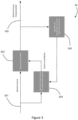
- FIG. 3 schematically illustrates a control scheme 30 implemented by the controller 110 in accordance with an example of the invention.
- the position signal 301 from the encoder 109 is received by the controller 110.
- the specification of the encoder 109 itself will define the resolution and precision of the measured rotor position.
- the controller 110 may therefore receive the encoder position signal in the form of a raw pulse count or Gamma count. This position signal is indicative of an angular position of the generator shaft 108.
- this raw position signal 301 would be provided to a low pass phase-locked loop function (or transfer function low pass filter) to determine the angular speed of the generator shaft
- a compensated or modified signal 302 (Gamma count compensated signal) is provided to a control function that uses generator position signal as an input, and/or a control block for determining the angular speed of the generator shaft 108.
- a compensation signal is applied to the position signal 301 at control block or module 303 to obtain the modified signal 302.
- the compensation signal is for modifying the raw position signal 301 to compensate for distortions in the raw position signal caused by imperfections in the encoder sensor 109.
- control block 303 is for obtaining a modified signal 302 that compensates for mechanical outrun caused by a misalignment of the encoder 109 relative to the axis of the generator shaft 108.
- control block 303 can be used for compensating to account for different or additional distortions caused by encoder imperfections, e.g. ovality.
- the high-level architecture 30 illustrated in Figure 3 indicates that the described example uses an adaptive mixed feedforward and feedback loop to compensate for mechanical outrun in the raw position signal 301 from the encoder 109.
- the raw position signal 301 is provided to a control block 304 as part of a feedforward loop.
- the control block 304 is for generating or determining the compensation signal that will be provided to the control block 303 to be applied to the position signal 301 so as to obtain the modified position signal 302.
- the compensation signal module 304 also receives a feedback signal from a further control block 305.
- control block 305 receives as input the modified position signal 302 obtained from the control block 303, and this is analysed to identify the phase and magnitude of the signal distortion caused by the encoder imperfection, e.g. the component of the signal indicative of mechanical outrun. As mentioned, this is then provided to the compensation signal module 304, which determines an oscillation signal having a determined phase and magnitude to counteract the outrun oscillation in the raw position signal 301.
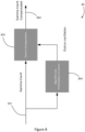
- Figure 4 illustrates a more detailed view of the high-level mixed feedforward and feedback control scheme or loop 30 of Figure 3 .
- Figure 4 also illustrates a more generalised version of the control scheme, as it provides for compensating both mechanical outrun and ovality in a position signal 301 received from the encoder 109.
- the control scheme can be further generalised to compensate for distortions in the position signal caused by further/different encoder imperfections. While the described examples target generator 1P (outrun) and 2P (ovality) frequencies, distortions at other generator frequencies (3P, 4P, etc.) may equally be compensated for in a corresponding manner.
- a first part 41 of the control loop architecture 30 relates to the determination of a compensation signal to compensate for mechanical outrun distortion in the raw position signal.
- a second part 42 of the control loop architecture 30 relates to the determination of a compensation signal to compensate for ovality distortion in the raw position signal.
- this module 304 includes two sub-modules, namely a sine-component module 3041 and a cosine-component module 3042.
- the sine-component module 3041 receives the Gamma count 301 and identifies or extracts the sine component of the signal 301.
- the cosine-component module 3042 receives the Gamma count 301 and identifies or extracts the cosine component of the signal 301.
- the modified or compensated signal 302 is provided as feedback to the outrun part 41 for the purpose of identifying the compensation gains that are to be applied to the compensation signals determined in the sub-modules 3041, 3042.
- the control module 305 includes a speed calculation sub-module 3051.
- the compensated signal 302 is received by the speed calculation sub-module 3051, which uses this received signal 302 to calculate the angular speed, e.g. by differentiating the received signal 302.
- This angular speed is then provided to a further sub-module 3052, which applies a band-pass filter having a centre frequency equal to outrun oscillations (i.e. 1P).
- the output of the sub-modules 3043, 3044 are the compensation signals to be applied to the raw position signal 301 to compensate for mechanical outrun in the raw position signal 301. Indeed, the compensation signals are combined/added to the raw position signal 301 in the module 303 (in particular, at the sub-modules 3031, 3032).
- the second, ovality part 42 of the architecture 30 has a corresponding structure to the first, outrun part 41, except that the resulting compensation signal is to compensate for ovality distortion in the raw position signal 301 (rather than outrun distortion).
- Sub-modules in the ovality part 42 performing like functions as in the outrun part 41 have been labelled with the same reference numerals.
- the sine and cosine-component modules 3041, 3042 of the ovality part 42 are applied to two times the Gamma count (position signal) 301. This is because the ovality distortion has 2P frequency.
- band-pass filter sub-module 3052 of the ovality part 42 instead of the applied band-pass filter having a centre frequency equal to outrun oscillations (i.e. 1P) as in the outrun part 41, it has a centre frequency equal to ovality oscillations (i.e. 2P). As such, this results in a filtered speed signal in the ovality part 42 that has only the ovality frequency.
- the aim of the adaptive control algorithm architecture 30 is to minimise a cross correlation of encoder distortion frequency (i.e. outrun and/or ovality frequency) between speed and position.
- encoder distortion frequency i.e. outrun and/or ovality frequency
- the mixed feedforward and feedback adaptive loop may be regarded as providing a particularly robust method for compensating for encoder imperfections.
- a determination of angular speed (based on the modified position signal 302) to be provided to control functions where generator speed is an input may be separate from the determination of angular speed in the speed calculation sub-modulation 3051.
- a single determination of angular speed based on the modified position signal 302 may be performed, where the obtained angular speed is both: provided for use in performing one or more control functions of the wind turbine; and, provided as feedback to a distortion phase and magnitude module for determining encoder imperfection compensation signals.
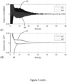
- Figure 5 shows plots of simulation results obtained when the described method is used to compensate for mechanical outrun in an output signal, received from the encoder 109, indicative of the angular position of the generator shaft 108.
- the results relate to a steady state speed of 440 rpm, with an outrun position sine component of 0.006 and an outrun position cosine component of 0.0025.
- Figure 5 shows plots of parameters illustrating how the method identifies, and compensates for, the mechanical outrun distortion over time.
- Figure 5(a) shows the sine and cosine gain components 51, 52
- Figure 5(b) shows the sine and cosine compensation components 53, 54
- Figure 5(c) shows the sine and cosine correlation components 55, 56
- Figure 5(d) shows the low-pass filtered sine and cosine correlation components 57, 58. It may be seen that the gains and compensation signals converge to optimum values over time while the cross-correlation signals are minimised.
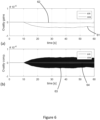
- Figures 6(a) to 6(d) show corresponding plots to Figures 5(a) to 5(d) simulation results obtained when the described method is used to compensate for ovality distortion, where parameters are indicated by reference numerals 61-68 (in a corresponding manner to reference numerals 51-58 in Figure 5 ).
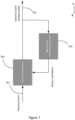
- Figure 7 schematically illustrates an alternative control scheme 70 (relative to the control scheme 30 of Figure 3 ) that may implemented by the controller 110 in accordance with an example of the invention.
- the control scheme 70 of Figure 7 is a purely feedback adaptive control loop for modifying the raw position signal 301 to obtain the modified/compensated position signal 302 that compensates for one or more encoder imperfections (e.g. outrun, ovality). That is, like in Figure 3 , the identification of gains in the scheme 70 of Figure 7 is based on a feedback loop using the modified position signal 302 (in particular, based on the calculated angular speed).
- the compensation signal in the scheme 70 of Figure 7 is also based on a feedback loop using the modified position signal 302.
- This feedback loop is represented as a single control block 704 to determine the compensation signal, which is then applied to the position signal 301 at control block 303 to obtain the modified position signal 302.
- FIG 8 schematically illustrates a further alternative control scheme 80 (relative to the control scheme 30 of Figure 3 and the control scheme 70 of Figure 7 ) that may implemented by the controller 110 in accordance with an example of the invention.
- the control scheme 80 of Figure 8 is a purely feedforward adaptive control loop for modifying the raw position signal 301 to obtain the modified/compensated position signal 302 that compensates for one or more encoder imperfections (e.g. outrun, ovality).
- the compensation signal in the scheme 80 of Figure 8 is based on a feedforward loop using the raw position signal 301.
- the identification of gains in the scheme 80 of Figure 8 is also based on a feedforward loop using the raw position signal 301.
- This feedforward loop is represented as a single control block 804 to determine the compensation signal, which is then applied to the position signal 301 at control block 303 to obtain the modified position signal 302.
- Figure 9 summarises the steps of a method 90 performed by the controller 110 for determining the angular position, and optionally speed, of the generator shaft 108 of the wind turbine 10.
- the method 90 includes receiving a position signal 301, from an encoder position sensor 109 of the wind turbine 10, indicative of an angular position of the generator shaft 108.
- the position signal 301 may be in the form of a pulse (Gamma) count signal.
- the method 90 includes determining a compensation signal to compensate for a disturbance signal in the received position signal indicative of an imperfection associated with the encoder position sensor. This may involve determining a gain of the compensation signal based on determined position and speed components from the position signal, the speed component being associated with the disturbance signal.
- the position component may include sine and cosine components of the position signal.
- the method 90 includes modifying the position signal by applying the determined compensation signal to the received position signal. This may involve adding the position and compensation signals together.
- the compensation signal may include components for compensating for one or more imperfections associated with the encoder sensor.
- the compensation signal may include components for compensating for mechanical outrun (1P frequency distortion) and/or ovality distortion (2P frequency distortion) in the position signal.
- the compensation signal may additionally or alternatively include components for compensating for different types of distortions in the position signal (e.g. 3P frequency distortion, 4P frequency distortion, etc.).
- the modified (compensated) position signal may then be provided to one or more control functions of the wind turbine 10 that use a generator position signal as an input.
- a generator speed signal may be determined as a derivative of the modified position signal.
- the generator speed signal is then optionally provided to one or more control functions of the wind turbine 10 that use a generator speed signal as an input.
- Such control functions may determine a control action for controlling the wind turbine 10 in dependence on the determined angular position and/or speed of the generator shaft 108.
- the control action could be for controlling the current from a converter of the wind turbine 10 to the generator 108, or controlling a pitch angle of the rotor blades 103.
- the method may include transmitting a control signal to a control component (e.g. a pitch actuator component for adjusting blade pitch) of the wind turbine 10 in accordance with the determined control action.
- the determination of generator shaft angular position and/or speed may also be used as part of a predictive maintenance scheme associated with the wind turbine 10.
- the encoder 109 fails then the wind turbine 10 may not be able to continue operation.
- the analysis of the method described herein can predict that an encoder is not functioning properly or will fail ahead of actually doing so, then this can minimise potential down time of the wind turbine.
- a warning signal may be raised.
- the encoder may then be checked to identify whether there is a hardware issue, e.g. a screw is loose, that is causing the relatively high distortion levels.
- the warning signal may indicate that the encoder should be checked immediately or when the wind turbine 10 is undergoing its next scheduled service. If the distortion levels are particularly high, then operation of the wind turbine 10 may be stopped until the issue is identified and corrected.
- the described method is also applicable for determining the angular position and speed of a different rotating component.
- the described method may be used to determine the angular position and/or speed of the rotor shaft.
- the described method may also be used to determine the angular position and/or speed of any suitable rotating component having an encoder for monitoring its position and providing output pulses indicative of its position.
Landscapes
- Engineering & Computer Science (AREA)
- Combustion & Propulsion (AREA)
- Life Sciences & Earth Sciences (AREA)
- Sustainable Development (AREA)
- Sustainable Energy (AREA)
- Chemical & Material Sciences (AREA)
- Mechanical Engineering (AREA)
- General Engineering & Computer Science (AREA)
- Physics & Mathematics (AREA)
- General Physics & Mathematics (AREA)
- Automation & Control Theory (AREA)
- Power Engineering (AREA)
- Wind Motors (AREA)
Claims (14)
- Verfahren zum Bestimmen einer Winkelposition einer Generatorwelle einer Windkraftanlage, wobei das Verfahren umfasst:Empfangen eines Positionssignals, das bezeichnend für eine Winkelposition der Generatorwelle ist, von einem Encoder-Positionssensor der Windkraftanlage;Bestimmen eines Kompensationssignals, um ein Störungssignal in dem empfangenen Positionssignal, das für eine Unvollkommenheit, die dem Encoder-Positionssensor zugeordnet ist, bezeichnend ist, zu kompensieren; undModifizieren des Positionssignals durch Anwenden des bestimmten Kompensationssignals auf das empfangene Positionssignal, um die Winkelposition zu bestimmen,dadurch gekennzeichnet, dassBestimmen des Kompensationssignals Folgendes umfasst:Bestimmen einer Positionskomponente des Positionssignals;Bestimmen eines Geschwindigkeitssignals basierend auf dem Positionssignal und Bestimmen einer Positionskomponente, die dem Störungssignal zugeordnet ist, in dem Geschwindigkeitssignal; undBestimmen einer Verstärkung des Kompensationssignals basierend auf der Positionskomponente und der Geschwindigkeitskomponente.
- Verfahren nach Anspruch 1, wobei Bestimmen der Geschwindigkeitskomponente Anwenden eines Bandpassfilters auf das Geschwindigkeitssignal umfasst, wobei der Bandpassfilter eine Mittenfrequenz aufweist, die gleich einer Frequenz des Störungssignals ist.
- Verfahren nach Anspruch 1 oder Anspruch 2, wobei:Bestimmen der Positionskomponente Identifizieren einer SinusPositionskomponente in dem Positionssignal und Identifizieren einer CosinusPositionskomponente in dem Positionssignal umfasst; undBestimmen der Verstärkung des Kompensationssignals Bestimmen einer Sinuskomponentenverstärkung umfasst, das Multiplizieren der Sinuspositionskomponente und der Geschwindigkeitskomponente umfasst, und Bestimmen einer Cosinuskomponentenverstärkung, das Multiplizieren der Cosinuspositionskomponente und der Geschwindigkeitskomponente umfasst.
- Verfahren nach Anspruch 3, wobei Bestimmen der Sinus- und Cosinuskomponentenverstärkungen Anwenden einer Störungssignalfilterfunktion auf Signale umfasst, die aus den jeweiligen Multiplikationsschritten erhalten werden, wobei die Störungssignalfilterfunktion mindestens einen von einem Tiefpassfilter und einem Integrator beinhaltet.
- Verfahren nach Anspruch 3 oder Anspruch 4, wobei das Kompensationssignal erste und eine zweite Kompensationskomponente beinhaltet, wobei die erste Kompensationskomponente durch Multiplizieren der Sinuspositionskomponente und der Cosinuskomponentenverstärkung bestimmt wird, und wobei die zweite Kompensationskomponente durch Multiplizieren der Cosinuspositionskomponente und der Sinuskomponentenverstärkung bestimmt wird.
- Verfahren nach Anspruch 5, wobei das Kompensationssignal durch Minimieren einer Kreuzkorrelation zwischen den Positionskomponenten und den Geschwindigkeitskomponenten der Frequenz des Störungssignals als Teil eines adaptiven Regelkreises bestimmt wird.
- Verfahren nach Anspruch 6, wobei der adaptive Regelkreis ein gemischter adaptiver Rückkopplungs- und Vorwärts-Regelkreis ist.
- Verfahren nach Anspruch 7, wobei:die Positionskomponenten aus dem empfangenen Positionssignal als Teil eines Vorsteuerschritts des adaptiven Regelkreises bestimmt werden; unddas Geschwindigkeitssignal aus dem modifizierten Positionssignal als Teil eines Rückkopplungsschritts des adaptiven Regelkreises bestimmt wird.
- Verfahren nach Anspruch 6, wobei der adaptive Regelkreis ein Rückkopplungsregelkreis ist, in dem die Positionskomponenten und das Geschwindigkeitssignal aus dem modifizierten Positionssignal bestimmt werden.
- Verfahren nach Anspruch 6, wobei der adaptive Regelkreis ein Vorwärtskopplungsregelkreis ist, in dem die Positionskomponenten und das Geschwindigkeitssignal aus dem empfangenen Positionssignal bestimmt werden.
- Verfahren nach einem vorstehenden Anspruch, wobei das Störungssignal mindestens einem entspricht von:mechanischem Nachlauf, der einem Ausrichtungsfehler des Encoder-Positionssensors zugeordnet ist und eine Frequenz aufweist, die einer mechanischen Geschwindigkeit des Generators entspricht; undOvalitätsverzerrung, die einer physischen Verformung des Encoder-Positionssensors zugeordnet ist und eine Frequenz aufweist, die der zweifachen mechanischen Geschwindigkeit des Generators entspricht.
- Verfahren nach einem vorstehenden Anspruch, wobei das Verfahren Bestimmen einer Steueraktion zum Steuern der Windkraftanlage in Abhängigkeit von der bestimmten Winkelposition umfasst; wobei die Steueraktion optional zum Steuern von mindestens einem dient von: einem Strom von einem Wandler der Windkraftanlage zu dem Generator; und einem Blattwinkel eines oder mehrerer Rotorblätter der Windkraftanlage; wobei das Verfahren weiter optional Übertragen eines Steuersignals umfasst, um eine oder mehrere Komponenten der Windkraftanlage in Abhängigkeit von der bestimmten Steueraktion zu steuern.
- Steuereinheit für eine Windkraftanlage, wobei die Steuereinheit dazu konfiguriert ist:ein Positionssignal von einem Encoder-Positionssensor der Windkraftanlage zu empfangen, das bezeichnend für eine Winkelposition einer Generatorwelle der Windkraftanlage ist;ein Kompensationssignal zu bestimmen, um ein Störungssignal in dem empfangenen Positionssignal, das bezeichnend für eine dem Encoder-Positionssensor zugeordnete Unvollkommenheit ist, zu kompensieren; unddas Positionssignal durch Anwenden des bestimmten Kompensationssignals auf das empfangene Positionssignal zu modifizieren, um die Winkelposition der Generatorwelle zu bestimmen,dadurch gekennzeichnet, dass der Schritt zum Bestimmen des Kompensationssignals Folgendes umfasst:Bestimmen einer Positionskomponente des Positionssignals;Bestimmen eines Geschwindigkeitssignals basierend auf dem Positionssignal, und Bestimmen einer Geschwindigkeitskomponente in dem Geschwindigkeitssignal, das dem Störungssignal zugeordnet ist; undBestimmen einer Verstärkung des Kompensationssignals basierend auf der Positionskomponente und der Geschwindigkeitskomponente.
- Windkraftanlage, die die Steuereinheit nach Anspruch 13 umfasst.
Applications Claiming Priority (1)
| Application Number | Priority Date | Filing Date | Title |
|---|---|---|---|
| DKPA202170562 | 2021-11-16 |
Publications (3)
| Publication Number | Publication Date |
|---|---|
| EP4180657A1 EP4180657A1 (de) | 2023-05-17 |
| EP4180657C0 EP4180657C0 (de) | 2025-05-07 |
| EP4180657B1 true EP4180657B1 (de) | 2025-05-07 |
Family
ID=84331730
Family Applications (1)
| Application Number | Title | Priority Date | Filing Date |
|---|---|---|---|
| EP22207182.1A Active EP4180657B1 (de) | 2021-11-16 | 2022-11-14 | Bestimmung der position eines windturbinengenerators |
Country Status (3)
| Country | Link |
|---|---|
| US (1) | US11815370B2 (de) |
| EP (1) | EP4180657B1 (de) |
| ES (1) | ES3029436T3 (de) |
Families Citing this family (1)
| Publication number | Priority date | Publication date | Assignee | Title |
|---|---|---|---|---|
| WO2025131201A1 (en) * | 2023-12-22 | 2025-06-26 | Vestas Wind Systems A/S | Determining rotor azimuth angle of a wind turbine |
Family Cites Families (9)
| Publication number | Priority date | Publication date | Assignee | Title |
|---|---|---|---|---|
| US6598196B1 (en) * | 2000-02-29 | 2003-07-22 | Agilent Technologies, Inc. | Technique for correcting errors in position encoders |
| JP2010130739A (ja) * | 2008-11-26 | 2010-06-10 | Hitachi Ltd | 風力発電システム |
| JP2013221404A (ja) | 2012-04-12 | 2013-10-28 | Yaskawa Electric Corp | 発電装置および発電システム |
| DE102013227055A1 (de) * | 2013-12-23 | 2015-06-25 | Robert Bosch Gmbh | Verfahren zum Bestimmen einer Drehwinkelstellung und/oder einer Drehzahl |
| US9651443B2 (en) | 2014-06-06 | 2017-05-16 | General Electric Company | System and method for protecting rotary machines |
| KR101834526B1 (ko) * | 2016-09-27 | 2018-04-19 | 성균관대학교산학협력단 | 마그네틱 엔코더의 출력 신호를 보상하는 장치 |
| US10436181B2 (en) * | 2017-02-16 | 2019-10-08 | General Electric Company | System and method for determining an estimated position of a wind turbine rotor shaft |
| US10781795B2 (en) | 2017-11-13 | 2020-09-22 | General Electric Company | Method and system for detecting a mass imbalance in a wind turbine rotor |
| US12078516B2 (en) * | 2020-12-11 | 2024-09-03 | Dmg Mori Co., Ltd. | Automatic correction method |
-
2022
- 2022-11-14 ES ES22207182T patent/ES3029436T3/es active Active
- 2022-11-14 EP EP22207182.1A patent/EP4180657B1/de active Active
- 2022-11-16 US US17/988,434 patent/US11815370B2/en active Active
Also Published As
| Publication number | Publication date |
|---|---|
| US20230152128A1 (en) | 2023-05-18 |
| EP4180657C0 (de) | 2025-05-07 |
| EP4180657A1 (de) | 2023-05-17 |
| ES3029436T3 (en) | 2025-06-24 |
| US11815370B2 (en) | 2023-11-14 |
Similar Documents
| Publication | Publication Date | Title |
|---|---|---|
| US20140167415A1 (en) | Method of wind turbine yaw angle control and wind turbine | |
| US8829699B2 (en) | Rotational speed control of a wind turbine based on rotor acceleration | |
| US11867150B2 (en) | Azimuth sensors in wind turbines | |
| US11754043B2 (en) | Method and system for controlling a wind turbine to reduce nacelle vibration | |
| EP2952860B1 (de) | System und verfahren zum schutz von rotierenden maschinen | |
| US12281639B2 (en) | Determining wind turbine rotor speed | |
| US10436181B2 (en) | System and method for determining an estimated position of a wind turbine rotor shaft | |
| EP4180657B1 (de) | Bestimmung der position eines windturbinengenerators | |
| US9897073B2 (en) | Method for damping torsional vibrations in a power generation plant | |
| US20140020465A1 (en) | Monitoring arrangement | |
| CN118414488A (zh) | 基于塔架测量值的风力涡轮机回旋模式控制 | |
| EP4448957B1 (de) | Windturbinenrotorblattwinkelverstellungssteuerung zur turmermüdungsverringerung | |
| US11237068B2 (en) | Method and device for the torque measurement in the drive train of a wind energy facility | |
| US20240413773A1 (en) | Control of a rotating electric machine | |
| CN115398099B (zh) | 使用修正功率参考控制风力涡轮机 | |
| EP3695112A1 (de) | Steuerungsverfahren zur steuerung einer windturbine und windturbine mit zur durchführung des steuerungsverfahrens konfigurierten steuermitteln | |
| Ono | A direct-drive motor control system and its features | |
| US12448948B1 (en) | System and method for monitoring vibrations in a drivetrain of a wind turbine | |
| WO2025131201A1 (en) | Determining rotor azimuth angle of a wind turbine | |
| JP5709646B2 (ja) | 回転角度計測方法およびエンジンバルブ制御方法 | |
| WO2024230991A1 (en) | Determining rotor electrical angle position of a wind turbine generator | |
| WO2025131200A1 (en) | Determining rotor azimuth angle of a wind turbine |
Legal Events
| Date | Code | Title | Description |
|---|---|---|---|
| PUAI | Public reference made under article 153(3) epc to a published international application that has entered the european phase |
Free format text: ORIGINAL CODE: 0009012 |
|
| STAA | Information on the status of an ep patent application or granted ep patent |
Free format text: STATUS: THE APPLICATION HAS BEEN PUBLISHED |
|
| AK | Designated contracting states |
Kind code of ref document: A1 Designated state(s): AL AT BE BG CH CY CZ DE DK EE ES FI FR GB GR HR HU IE IS IT LI LT LU LV MC ME MK MT NL NO PL PT RO RS SE SI SK SM TR |
|
| STAA | Information on the status of an ep patent application or granted ep patent |
Free format text: STATUS: REQUEST FOR EXAMINATION WAS MADE |
|
| 17P | Request for examination filed |
Effective date: 20231115 |
|
| RBV | Designated contracting states (corrected) |
Designated state(s): AL AT BE BG CH CY CZ DE DK EE ES FI FR GB GR HR HU IE IS IT LI LT LU LV MC ME MK MT NL NO PL PT RO RS SE SI SK SM TR |
|
| GRAP | Despatch of communication of intention to grant a patent |
Free format text: ORIGINAL CODE: EPIDOSNIGR1 |
|
| STAA | Information on the status of an ep patent application or granted ep patent |
Free format text: STATUS: GRANT OF PATENT IS INTENDED |
|
| GRAS | Grant fee paid |
Free format text: ORIGINAL CODE: EPIDOSNIGR3 |
|
| INTG | Intention to grant announced |
Effective date: 20250227 |
|
| GRAA | (expected) grant |
Free format text: ORIGINAL CODE: 0009210 |
|
| STAA | Information on the status of an ep patent application or granted ep patent |
Free format text: STATUS: THE PATENT HAS BEEN GRANTED |
|
| AK | Designated contracting states |
Kind code of ref document: B1 Designated state(s): AL AT BE BG CH CY CZ DE DK EE ES FI FR GB GR HR HU IE IS IT LI LT LU LV MC ME MK MT NL NO PL PT RO RS SE SI SK SM TR |
|
| REG | Reference to a national code |
Ref country code: GB Ref legal event code: FG4D |
|
| REG | Reference to a national code |
Ref country code: CH Ref legal event code: EP |
|
| REG | Reference to a national code |
Ref country code: DE Ref legal event code: R096 Ref document number: 602022014197 Country of ref document: DE |
|
| REG | Reference to a national code |
Ref country code: IE Ref legal event code: FG4D |
|
| REG | Reference to a national code |
Ref country code: ES Ref legal event code: FG2A Ref document number: 3029436 Country of ref document: ES Kind code of ref document: T3 Effective date: 20250624 |
|
| U01 | Request for unitary effect filed |
Effective date: 20250522 |
|
| U07 | Unitary effect registered |
Designated state(s): AT BE BG DE DK EE FI FR IT LT LU LV MT NL PT RO SE SI Effective date: 20250602 |
|
| PG25 | Lapsed in a contracting state [announced via postgrant information from national office to epo] |
Ref country code: GR Free format text: LAPSE BECAUSE OF FAILURE TO SUBMIT A TRANSLATION OF THE DESCRIPTION OR TO PAY THE FEE WITHIN THE PRESCRIBED TIME-LIMIT Effective date: 20250808 Ref country code: NO Free format text: LAPSE BECAUSE OF FAILURE TO SUBMIT A TRANSLATION OF THE DESCRIPTION OR TO PAY THE FEE WITHIN THE PRESCRIBED TIME-LIMIT Effective date: 20250807 |
|
| PG25 | Lapsed in a contracting state [announced via postgrant information from national office to epo] |
Ref country code: PL Free format text: LAPSE BECAUSE OF FAILURE TO SUBMIT A TRANSLATION OF THE DESCRIPTION OR TO PAY THE FEE WITHIN THE PRESCRIBED TIME-LIMIT Effective date: 20250507 |
|
| PG25 | Lapsed in a contracting state [announced via postgrant information from national office to epo] |
Ref country code: HR Free format text: LAPSE BECAUSE OF FAILURE TO SUBMIT A TRANSLATION OF THE DESCRIPTION OR TO PAY THE FEE WITHIN THE PRESCRIBED TIME-LIMIT Effective date: 20250507 |
|
| PG25 | Lapsed in a contracting state [announced via postgrant information from national office to epo] |
Ref country code: RS Free format text: LAPSE BECAUSE OF FAILURE TO SUBMIT A TRANSLATION OF THE DESCRIPTION OR TO PAY THE FEE WITHIN THE PRESCRIBED TIME-LIMIT Effective date: 20250807 |
|
| PG25 | Lapsed in a contracting state [announced via postgrant information from national office to epo] |
Ref country code: IS Free format text: LAPSE BECAUSE OF FAILURE TO SUBMIT A TRANSLATION OF THE DESCRIPTION OR TO PAY THE FEE WITHIN THE PRESCRIBED TIME-LIMIT Effective date: 20250907 |