EP4180146A1 - Verfahren zur herstellung eines heisspressgeformten elements mit hervorragender produzierbarkeit, schweissbarkeit und formbarkeit - Google Patents
Verfahren zur herstellung eines heisspressgeformten elements mit hervorragender produzierbarkeit, schweissbarkeit und formbarkeit Download PDFInfo
- Publication number
- EP4180146A1 EP4180146A1 EP20944436.3A EP20944436A EP4180146A1 EP 4180146 A1 EP4180146 A1 EP 4180146A1 EP 20944436 A EP20944436 A EP 20944436A EP 4180146 A1 EP4180146 A1 EP 4180146A1
- Authority
- EP
- European Patent Office
- Prior art keywords
- section
- blank
- heating
- temperature
- thickness
- Prior art date
- Legal status (The legal status is an assumption and is not a legal conclusion. Google has not performed a legal analysis and makes no representation as to the accuracy of the status listed.)
- Pending
Links
Images

Classifications
-
- B—PERFORMING OPERATIONS; TRANSPORTING
- B21—MECHANICAL METAL-WORKING WITHOUT ESSENTIALLY REMOVING MATERIAL; PUNCHING METAL
- B21D—WORKING OR PROCESSING OF SHEET METAL OR METAL TUBES, RODS OR PROFILES WITHOUT ESSENTIALLY REMOVING MATERIAL; PUNCHING METAL
- B21D22/00—Shaping without cutting, by stamping, spinning, or deep-drawing
- B21D22/02—Stamping using rigid devices or tools
- B21D22/022—Stamping using rigid devices or tools by heating the blank or stamping associated with heat treatment
-
- C—CHEMISTRY; METALLURGY
- C21—METALLURGY OF IRON
- C21D—MODIFYING THE PHYSICAL STRUCTURE OF FERROUS METALS; GENERAL DEVICES FOR HEAT TREATMENT OF FERROUS OR NON-FERROUS METALS OR ALLOYS; MAKING METAL MALLEABLE, e.g. BY DECARBURISATION OR TEMPERING
- C21D1/00—General methods or devices for heat treatment, e.g. annealing, hardening, quenching or tempering
- C21D1/62—Quenching devices
- C21D1/673—Quenching devices for die quenching
-
- B—PERFORMING OPERATIONS; TRANSPORTING
- B21—MECHANICAL METAL-WORKING WITHOUT ESSENTIALLY REMOVING MATERIAL; PUNCHING METAL
- B21C—MANUFACTURE OF METAL SHEETS, WIRE, RODS, TUBES, PROFILES OR LIKE SEMI-MANUFACTURED PRODUCTS OTHERWISE THAN BY ROLLING; AUXILIARY OPERATIONS USED IN CONNECTION WITH METAL-WORKING WITHOUT ESSENTIALLY REMOVING MATERIAL
- B21C23/00—Extruding metal; Impact extrusion
- B21C23/002—Extruding materials of special alloys so far as the composition of the alloy requires or permits special extruding methods of sequences
-
- B—PERFORMING OPERATIONS; TRANSPORTING
- B21—MECHANICAL METAL-WORKING WITHOUT ESSENTIALLY REMOVING MATERIAL; PUNCHING METAL
- B21D—WORKING OR PROCESSING OF SHEET METAL OR METAL TUBES, RODS OR PROFILES WITHOUT ESSENTIALLY REMOVING MATERIAL; PUNCHING METAL
- B21D22/00—Shaping without cutting, by stamping, spinning, or deep-drawing
- B21D22/20—Deep-drawing
- B21D22/208—Deep-drawing by heating the blank or deep-drawing associated with heat treatment
-
- B—PERFORMING OPERATIONS; TRANSPORTING
- B21—MECHANICAL METAL-WORKING WITHOUT ESSENTIALLY REMOVING MATERIAL; PUNCHING METAL
- B21C—MANUFACTURE OF METAL SHEETS, WIRE, RODS, TUBES, PROFILES OR LIKE SEMI-MANUFACTURED PRODUCTS OTHERWISE THAN BY ROLLING; AUXILIARY OPERATIONS USED IN CONNECTION WITH METAL-WORKING WITHOUT ESSENTIALLY REMOVING MATERIAL
- B21C29/00—Cooling or heating extruded work or parts of the extrusion press
- B21C29/003—Cooling or heating of work
-
- B—PERFORMING OPERATIONS; TRANSPORTING
- B21—MECHANICAL METAL-WORKING WITHOUT ESSENTIALLY REMOVING MATERIAL; PUNCHING METAL
- B21D—WORKING OR PROCESSING OF SHEET METAL OR METAL TUBES, RODS OR PROFILES WITHOUT ESSENTIALLY REMOVING MATERIAL; PUNCHING METAL
- B21D37/00—Tools as parts of machines covered by this subclass
- B21D37/16—Heating or cooling
-
- B—PERFORMING OPERATIONS; TRANSPORTING
- B32—LAYERED PRODUCTS
- B32B—LAYERED PRODUCTS, i.e. PRODUCTS BUILT-UP OF STRATA OF FLAT OR NON-FLAT, e.g. CELLULAR OR HONEYCOMB, FORM
- B32B15/00—Layered products comprising a layer of metal
- B32B15/01—Layered products comprising a layer of metal all layers being exclusively metallic
- B32B15/012—Layered products comprising a layer of metal all layers being exclusively metallic one layer being formed of an iron alloy or steel, another layer being formed of aluminium or an aluminium alloy
-
- C—CHEMISTRY; METALLURGY
- C21—METALLURGY OF IRON
- C21D—MODIFYING THE PHYSICAL STRUCTURE OF FERROUS METALS; GENERAL DEVICES FOR HEAT TREATMENT OF FERROUS OR NON-FERROUS METALS OR ALLOYS; MAKING METAL MALLEABLE, e.g. BY DECARBURISATION OR TEMPERING
- C21D1/00—General methods or devices for heat treatment, e.g. annealing, hardening, quenching or tempering
- C21D1/18—Hardening; Quenching with or without subsequent tempering
-
- C—CHEMISTRY; METALLURGY
- C21—METALLURGY OF IRON
- C21D—MODIFYING THE PHYSICAL STRUCTURE OF FERROUS METALS; GENERAL DEVICES FOR HEAT TREATMENT OF FERROUS OR NON-FERROUS METALS OR ALLOYS; MAKING METAL MALLEABLE, e.g. BY DECARBURISATION OR TEMPERING
- C21D6/00—Heat treatment of ferrous alloys
-
- C—CHEMISTRY; METALLURGY
- C21—METALLURGY OF IRON
- C21D—MODIFYING THE PHYSICAL STRUCTURE OF FERROUS METALS; GENERAL DEVICES FOR HEAT TREATMENT OF FERROUS OR NON-FERROUS METALS OR ALLOYS; MAKING METAL MALLEABLE, e.g. BY DECARBURISATION OR TEMPERING
- C21D6/00—Heat treatment of ferrous alloys
- C21D6/002—Heat treatment of ferrous alloys containing Cr
-
- C—CHEMISTRY; METALLURGY
- C21—METALLURGY OF IRON
- C21D—MODIFYING THE PHYSICAL STRUCTURE OF FERROUS METALS; GENERAL DEVICES FOR HEAT TREATMENT OF FERROUS OR NON-FERROUS METALS OR ALLOYS; MAKING METAL MALLEABLE, e.g. BY DECARBURISATION OR TEMPERING
- C21D6/00—Heat treatment of ferrous alloys
- C21D6/005—Heat treatment of ferrous alloys containing Mn
-
- C—CHEMISTRY; METALLURGY
- C21—METALLURGY OF IRON
- C21D—MODIFYING THE PHYSICAL STRUCTURE OF FERROUS METALS; GENERAL DEVICES FOR HEAT TREATMENT OF FERROUS OR NON-FERROUS METALS OR ALLOYS; MAKING METAL MALLEABLE, e.g. BY DECARBURISATION OR TEMPERING
- C21D6/00—Heat treatment of ferrous alloys
- C21D6/008—Heat treatment of ferrous alloys containing Si
-
- C—CHEMISTRY; METALLURGY
- C21—METALLURGY OF IRON
- C21D—MODIFYING THE PHYSICAL STRUCTURE OF FERROUS METALS; GENERAL DEVICES FOR HEAT TREATMENT OF FERROUS OR NON-FERROUS METALS OR ALLOYS; MAKING METAL MALLEABLE, e.g. BY DECARBURISATION OR TEMPERING
- C21D7/00—Modifying the physical properties of iron or steel by deformation
- C21D7/13—Modifying the physical properties of iron or steel by deformation by hot working
-
- C—CHEMISTRY; METALLURGY
- C21—METALLURGY OF IRON
- C21D—MODIFYING THE PHYSICAL STRUCTURE OF FERROUS METALS; GENERAL DEVICES FOR HEAT TREATMENT OF FERROUS OR NON-FERROUS METALS OR ALLOYS; MAKING METAL MALLEABLE, e.g. BY DECARBURISATION OR TEMPERING
- C21D8/00—Modifying the physical properties by deformation combined with, or followed by, heat treatment
-
- C—CHEMISTRY; METALLURGY
- C21—METALLURGY OF IRON
- C21D—MODIFYING THE PHYSICAL STRUCTURE OF FERROUS METALS; GENERAL DEVICES FOR HEAT TREATMENT OF FERROUS OR NON-FERROUS METALS OR ALLOYS; MAKING METAL MALLEABLE, e.g. BY DECARBURISATION OR TEMPERING
- C21D9/00—Heat treatment, e.g. annealing, hardening, quenching or tempering, adapted for particular articles; Furnaces therefor
- C21D9/46—Heat treatment, e.g. annealing, hardening, quenching or tempering, adapted for particular articles; Furnaces therefor for sheet metals
-
- C—CHEMISTRY; METALLURGY
- C21—METALLURGY OF IRON
- C21D—MODIFYING THE PHYSICAL STRUCTURE OF FERROUS METALS; GENERAL DEVICES FOR HEAT TREATMENT OF FERROUS OR NON-FERROUS METALS OR ALLOYS; MAKING METAL MALLEABLE, e.g. BY DECARBURISATION OR TEMPERING
- C21D9/00—Heat treatment, e.g. annealing, hardening, quenching or tempering, adapted for particular articles; Furnaces therefor
- C21D9/52—Heat treatment, e.g. annealing, hardening, quenching or tempering, adapted for particular articles; Furnaces therefor for wires; for strips ; for rods of unlimited length
- C21D9/54—Furnaces for treating strips or wire
- C21D9/56—Continuous furnaces for strip or wire
-
- C—CHEMISTRY; METALLURGY
- C22—METALLURGY; FERROUS OR NON-FERROUS ALLOYS; TREATMENT OF ALLOYS OR NON-FERROUS METALS
- C22C—ALLOYS
- C22C21/00—Alloys based on aluminium
- C22C21/02—Alloys based on aluminium with silicon as the next major constituent
-
- C—CHEMISTRY; METALLURGY
- C22—METALLURGY; FERROUS OR NON-FERROUS ALLOYS; TREATMENT OF ALLOYS OR NON-FERROUS METALS
- C22C—ALLOYS
- C22C38/00—Ferrous alloys, e.g. steel alloys
- C22C38/18—Ferrous alloys, e.g. steel alloys containing chromium
- C22C38/32—Ferrous alloys, e.g. steel alloys containing chromium with boron
-
- C—CHEMISTRY; METALLURGY
- C23—COATING METALLIC MATERIAL; COATING MATERIAL WITH METALLIC MATERIAL; CHEMICAL SURFACE TREATMENT; DIFFUSION TREATMENT OF METALLIC MATERIAL; COATING BY VACUUM EVAPORATION, BY SPUTTERING, BY ION IMPLANTATION OR BY CHEMICAL VAPOUR DEPOSITION, IN GENERAL; INHIBITING CORROSION OF METALLIC MATERIAL OR INCRUSTATION IN GENERAL
- C23C—COATING METALLIC MATERIAL; COATING MATERIAL WITH METALLIC MATERIAL; SURFACE TREATMENT OF METALLIC MATERIAL BY DIFFUSION INTO THE SURFACE, BY CHEMICAL CONVERSION OR SUBSTITUTION; COATING BY VACUUM EVAPORATION, BY SPUTTERING, BY ION IMPLANTATION OR BY CHEMICAL VAPOUR DEPOSITION, IN GENERAL
- C23C2/00—Hot-dipping or immersion processes for applying the coating material in the molten state without affecting the shape; Apparatus therefor
- C23C2/04—Hot-dipping or immersion processes for applying the coating material in the molten state without affecting the shape; Apparatus therefor characterised by the coating material
- C23C2/12—Aluminium or alloys based thereon
-
- C—CHEMISTRY; METALLURGY
- C23—COATING METALLIC MATERIAL; COATING MATERIAL WITH METALLIC MATERIAL; CHEMICAL SURFACE TREATMENT; DIFFUSION TREATMENT OF METALLIC MATERIAL; COATING BY VACUUM EVAPORATION, BY SPUTTERING, BY ION IMPLANTATION OR BY CHEMICAL VAPOUR DEPOSITION, IN GENERAL; INHIBITING CORROSION OF METALLIC MATERIAL OR INCRUSTATION IN GENERAL
- C23C—COATING METALLIC MATERIAL; COATING MATERIAL WITH METALLIC MATERIAL; SURFACE TREATMENT OF METALLIC MATERIAL BY DIFFUSION INTO THE SURFACE, BY CHEMICAL CONVERSION OR SUBSTITUTION; COATING BY VACUUM EVAPORATION, BY SPUTTERING, BY ION IMPLANTATION OR BY CHEMICAL VAPOUR DEPOSITION, IN GENERAL
- C23C2/00—Hot-dipping or immersion processes for applying the coating material in the molten state without affecting the shape; Apparatus therefor
- C23C2/26—After-treatment
- C23C2/28—Thermal after-treatment, e.g. treatment in oil bath
- C23C2/29—Cooling or quenching
-
- C—CHEMISTRY; METALLURGY
- C23—COATING METALLIC MATERIAL; COATING MATERIAL WITH METALLIC MATERIAL; CHEMICAL SURFACE TREATMENT; DIFFUSION TREATMENT OF METALLIC MATERIAL; COATING BY VACUUM EVAPORATION, BY SPUTTERING, BY ION IMPLANTATION OR BY CHEMICAL VAPOUR DEPOSITION, IN GENERAL; INHIBITING CORROSION OF METALLIC MATERIAL OR INCRUSTATION IN GENERAL
- C23C—COATING METALLIC MATERIAL; COATING MATERIAL WITH METALLIC MATERIAL; SURFACE TREATMENT OF METALLIC MATERIAL BY DIFFUSION INTO THE SURFACE, BY CHEMICAL CONVERSION OR SUBSTITUTION; COATING BY VACUUM EVAPORATION, BY SPUTTERING, BY ION IMPLANTATION OR BY CHEMICAL VAPOUR DEPOSITION, IN GENERAL
- C23C28/00—Coating for obtaining at least two superposed coatings either by methods not provided for in a single one of groups C23C2/00 - C23C26/00 or by combinations of methods provided for in subclasses C23C and C25C or C25D
- C23C28/02—Coating for obtaining at least two superposed coatings either by methods not provided for in a single one of groups C23C2/00 - C23C26/00 or by combinations of methods provided for in subclasses C23C and C25C or C25D only coatings only including layers of metallic material
- C23C28/021—Coating for obtaining at least two superposed coatings either by methods not provided for in a single one of groups C23C2/00 - C23C26/00 or by combinations of methods provided for in subclasses C23C and C25C or C25D only coatings only including layers of metallic material including at least one metal alloy layer
-
- C—CHEMISTRY; METALLURGY
- C23—COATING METALLIC MATERIAL; COATING MATERIAL WITH METALLIC MATERIAL; CHEMICAL SURFACE TREATMENT; DIFFUSION TREATMENT OF METALLIC MATERIAL; COATING BY VACUUM EVAPORATION, BY SPUTTERING, BY ION IMPLANTATION OR BY CHEMICAL VAPOUR DEPOSITION, IN GENERAL; INHIBITING CORROSION OF METALLIC MATERIAL OR INCRUSTATION IN GENERAL
- C23C—COATING METALLIC MATERIAL; COATING MATERIAL WITH METALLIC MATERIAL; SURFACE TREATMENT OF METALLIC MATERIAL BY DIFFUSION INTO THE SURFACE, BY CHEMICAL CONVERSION OR SUBSTITUTION; COATING BY VACUUM EVAPORATION, BY SPUTTERING, BY ION IMPLANTATION OR BY CHEMICAL VAPOUR DEPOSITION, IN GENERAL
- C23C28/00—Coating for obtaining at least two superposed coatings either by methods not provided for in a single one of groups C23C2/00 - C23C26/00 or by combinations of methods provided for in subclasses C23C and C25C or C25D
- C23C28/02—Coating for obtaining at least two superposed coatings either by methods not provided for in a single one of groups C23C2/00 - C23C26/00 or by combinations of methods provided for in subclasses C23C and C25C or C25D only coatings only including layers of metallic material
- C23C28/028—Including graded layers in composition or in physical properties, e.g. density, porosity, grain size
-
- C—CHEMISTRY; METALLURGY
- C23—COATING METALLIC MATERIAL; COATING MATERIAL WITH METALLIC MATERIAL; CHEMICAL SURFACE TREATMENT; DIFFUSION TREATMENT OF METALLIC MATERIAL; COATING BY VACUUM EVAPORATION, BY SPUTTERING, BY ION IMPLANTATION OR BY CHEMICAL VAPOUR DEPOSITION, IN GENERAL; INHIBITING CORROSION OF METALLIC MATERIAL OR INCRUSTATION IN GENERAL
- C23C—COATING METALLIC MATERIAL; COATING MATERIAL WITH METALLIC MATERIAL; SURFACE TREATMENT OF METALLIC MATERIAL BY DIFFUSION INTO THE SURFACE, BY CHEMICAL CONVERSION OR SUBSTITUTION; COATING BY VACUUM EVAPORATION, BY SPUTTERING, BY ION IMPLANTATION OR BY CHEMICAL VAPOUR DEPOSITION, IN GENERAL
- C23C30/00—Coating with metallic material characterised only by the composition of the metallic material, i.e. not characterised by the coating process
-
- C—CHEMISTRY; METALLURGY
- C22—METALLURGY; FERROUS OR NON-FERROUS ALLOYS; TREATMENT OF ALLOYS OR NON-FERROUS METALS
- C22C—ALLOYS
- C22C38/00—Ferrous alloys, e.g. steel alloys
- C22C38/001—Ferrous alloys, e.g. steel alloys containing N
-
- C—CHEMISTRY; METALLURGY
- C22—METALLURGY; FERROUS OR NON-FERROUS ALLOYS; TREATMENT OF ALLOYS OR NON-FERROUS METALS
- C22C—ALLOYS
- C22C38/00—Ferrous alloys, e.g. steel alloys
- C22C38/002—Ferrous alloys, e.g. steel alloys containing In, Mg, or other elements not provided for in one single group C22C38/001 - C22C38/60
-
- C—CHEMISTRY; METALLURGY
- C22—METALLURGY; FERROUS OR NON-FERROUS ALLOYS; TREATMENT OF ALLOYS OR NON-FERROUS METALS
- C22C—ALLOYS
- C22C38/00—Ferrous alloys, e.g. steel alloys
- C22C38/02—Ferrous alloys, e.g. steel alloys containing silicon
-
- C—CHEMISTRY; METALLURGY
- C22—METALLURGY; FERROUS OR NON-FERROUS ALLOYS; TREATMENT OF ALLOYS OR NON-FERROUS METALS
- C22C—ALLOYS
- C22C38/00—Ferrous alloys, e.g. steel alloys
- C22C38/04—Ferrous alloys, e.g. steel alloys containing manganese
-
- C—CHEMISTRY; METALLURGY
- C22—METALLURGY; FERROUS OR NON-FERROUS ALLOYS; TREATMENT OF ALLOYS OR NON-FERROUS METALS
- C22C—ALLOYS
- C22C38/00—Ferrous alloys, e.g. steel alloys
- C22C38/06—Ferrous alloys, e.g. steel alloys containing aluminium
Definitions
- This application relates to a method of manufacturing hot press-formed member having excellent productivity, weldability and formability
- high-strength steel utilizing a hot press forming method has been actively applied.
- heating and quenching processes of a material are necessarily required.
- An aluminum plated steel material or aluminum alloy plated steel material is used to prevent scale from occurring at high temperatures.
- An aluminum plated steel material or an aluminum alloy plated steel material has an issue on melting of a plating layer during rapid heating, and is generally heated at a low rate in an atmospheric heating furnace.
- heating is performed in a furnace set to the same atmospheric temperature or performed in a continuous heating furnace such as a roller hearth furnace having a plurality of heating zones in such a manner that an atmospheric temperature is sequentially increased.
- heating is performed at a slow rate, and thus, heating should be performed in a heating furnace for a certain period of time to secure time required to reach a target temperature.
- productivity may be deteriorated due to an increase in maintaining time in the heating furnace.
- a heating temperature may be increased to reduce in-furnace maintenance time.
- the heating temperature is increased, and thus, a thickness of a diffusion layer in an alloy layer is increased to cause poor weldability.
- An aspect of the present disclosure is to provide a method of manufacturing a hot press-formed member having improved productivity, weldability, and formability.
- a method of manufacturing a hot press-formed member comprises heating a blank of an aluminum-based plated steel sheet in a heating furnace, removing the heated blank from the heating furnace and conveying the removed blank between an upper mold portion and a lower mold portion of a mold, mounted on a press, to be seated; and performing a forming process after the upper mold portion of the mold is in contact with the seated blank.
- the heating furnace is a continuous heating furnace comprising section A, section B, and section C provided in a conveying direction of a blank.
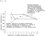
- Heating in section A satisfies conditions specified by a figure 'abcde' having cumulative in-furnace maintaining times and in-furnace atmospheric temperature coordinates of approximately a(0.2 min, 750°C), b(1.0 min, 750°C), c(1.0 min, 800°C), d(1.5 min, 900°C), and e(0.2 min, 900°C).
- Heating in section B satisfies conditions specified by a figure ⁇ fghi' having cumulative in-furnace maintaining times and atmospheric temperature coordinates of approximately f 1.3 + t ⁇ 1.2 0.6 ⁇ 0.5 min , 930 ° C , g 3.8 + t ⁇ 1.2 0.6 ⁇ 0.5 min , 930 ° C , h 3.3 + t ⁇ 1.2 0.6 ⁇ 0.5 min , 960 ° C , and i 0.8 + t ⁇ 1.2 0.6 ⁇ 0.5 min , 960 ° C .
- Heating in section C satisfies conditions specified by a figure 'jklm' having cumulative in-furnace maintaining times and atmospheric temperature coordinates of approximately j 3.7 + t ⁇ 1.2 0.6 min , 870 ° C , k 11.7 + t ⁇ 1.2 0.6 ⁇ 2 min , 870 ° C , l 7.03 + t ⁇ 1.2 0.6 ⁇ 2 min , 940 ° C , and m 2.53 + t ⁇ 1.2 0.6 min , 940 ° C .
- a highest atmospheric temperature of section C is lower than a highest atmospheric temperature of section B. Relational Expression 1 is satisfied.
- a time required before the forming process is performed after the blank is seated is two seconds or less.
- T denotes a sum of time required for conveying and seating a blank and time required before forming is performed after the blank is seated and a unit thereof second (s)
- t denotes a thickness of a blank and a unit thereof is millimeters (mm)
- temp denotes a furnace extraction temperature and a unit thereof is degrees Celsius (°C).
- a method of manufacturing a hot press-formed member having improved productivity, weldability, and formability could be provided.
- a method of manufacturing a hot press-formed member may comprise heating a blank of an aluminum-based plated steel sheet in a heating furnace, removing the heated blank from the heating furnace and conveying the removed blank between an upper mold portion and a lower mold portion of a mold, mounted on a press, to be seated, and performing a forming process after the upper mold portion of the mold is in contact with the seated blank.
- the method of manufacturing a hot press-formed member may further comprise an in-mold cooling step, in which the upper mold portion of the mold reaches a press bottom dead center and is then maintained to quench a formed material, and a step of removing a cooled formed member.
- the aluminum-based plated steel sheet may be an aluminum plated steel sheet or an aluminum alloy plated steel sheet.
- a plating layer may comprise, by weight percentage (wt%), 5 to 11% of silicon (Si), 4.5% or less of iron (Fe), and a balance of aluminum (Al) and unavoidable impurities.
- a base steel sheet may include, by wt%, 0.1 to 0.5% of carbon (C), 0.1 to 2% of silicon (Si), 0.5 to 3% of manganese (Mn), 0.01 to 0.5% of chromium (Cr), 0.001 to 1.0% of aluminum (Al), 0.05% or less of phosphorus (P), 0.02% or less of sulfur (S), 0.02% or less of nitrogen (N), 0.002 to 0.005% of boron (B), and a balance of iron (Fe) and unavoidable impurities.
- C carbon
- Si silicon
- Mn manganese
- Cr chromium
- Al aluminum
- P phosphorus
- S sulfur
- N nitrogen
- B boron
- Fe iron
- the heating furnace may be a continuous heating furnace comprising section A, section B, and section C provided sequentially in a conveying direction of the blank.
- section A, section B, and section C do not need to be provided adjacent to each other in the conveying direction of the blank, and have only to satisfy the above sequence in the conveying direction of the blank.
- each of section A, section B, and section C may include a single heating zone, or a plurality of heating zones may be included in each of section A, section B, and section C.
- An additional section, set to a temperature between pre-step and post-step temperature ranges, may be further provided between the respective sections (for example, between sections A and B or between sections B and C).
- heating is performed in a heating furnace set to the same atmospheric temperature, or heating is performed in such a manner that an atmospheric temperature is sequentially increased by a continuous heating furnace such as a roller hearth furnace having a plurality of heating zones.
- heating in a heating furnace is necessarily performed for a certain period of time to secure time required to reach a target temperature.
- productivity may be deteriorated due to an increase in maintaining time in the heating furnace.
- the present inventors found that when an atmospheric temperature is set to be high while increasing a temperature of section B, heating is performed more rapidly than a conventional heating furnace setting method, and thus, in-furnace maintaining time may be reduced to improve productivity.
- the present inventors found that when the temperature of section C in a subsequent process is set to be lower than the temperature of section B, the above-described process, a final heating temperature is set to be low, and thus, poor weldability may be addressed.
- a factor, determining the above-mentioned productivity may be significant reduction of time required to reach 900°C, significant reduction of time required for a temperature of a material to reach a take-out temperature of the heating furnace in a section in which a material is removed from the heating furnace, or whether overall cumulative maintaining time in the heating furnace until the material is removed of the heating furnace is less than or equal to time for which a diffusion layer has a thickness of 15 um.
- productivity may be improved.
- section B set to the above-mentioned high temperature is too wide, the thickness of the diffusion layer may be increased as time required to be heated and maintained at a high temperature is significantly reduced. Thus, weldability may be deteriorated.
- section B set to the high temperature is too narrow, an effect of improving productivity by a high heating rate may not be obtained.
- a large amount of energy is consumed to maintain section A, an initial section of the heating furnace, at a high temperature. At an initial stage of temperature rising, it is unnecessary to set the temperature to an unnecessarily high atmospheric temperature.
- the temperature may not be set to a high atmospheric temperature from the beginning due to heat radiation from an open structure of an injection portion of a material and injection of a cold material.
- the temperature may be set to be a relatively low temperature.
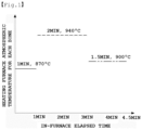
- a heating pattern illustrated in FIG. 1 was performed on an aluminum plated material having a thickness of 1.2 mm.
- a temperature was set to a relatively low temperature in consideration of energy saving and inability to be set to a high atmospheric temperature.
- the temperature was set to a highest temperature to rapidly heat the material, and thus, the material was set to reach a sufficient temperature.
- section C after the material reached the sufficient temperature, the temperature was reset to a lower temperature than that of section B.
- the material having a thickness of 1.2 mm is maintained at a temperature of 900°C at a point in time at which cumulative furnace maintaining time is 4.5 minutes.
- This result was derived from a result of heating analysis on radiation and convective heat transfer in a heating furnace atmosphere. Hereinafter, heating conditions in each section will be described in further detail.
- an atmospheric temperature in each section to be described later may refer to an atmosphere maintaining temperature in each heating zone (for example, a temperature of a region in which an actual atmospheric temperature is maintained in a single heating zone) in a heating furnace having a plurality of heating zones and being able to control atmospheric temperatures of the respective heating zones to be distinguished from each other.
- an atmosphere maintaining temperature in a single heating zone may be a temperature measured at a representative point of a region in which the actual atmospheric temperature is maintained.
- an example of the representative point may be a point disposed in a center (1/2) in a length direction, a 1/4 location in a width direction, and spaced apart from a blank location by 250 mm in a height direction with respect to a single heating zone.
- the atmospheric temperature in each section is regarded as being maintained at the atmosphere maintaining temperature in each heating zone corresponding to each section.
- cumulative in-furnace maintaining time in each section may refer to a maintaining time from a point in time at which a blank, a material, is injected into the heating furnace to a point in time at which the blank is removed of a last heating zone, among the heating zones corresponding to the above-mentioned sections.
- the heating zones may be separated by a partition wall or the like, or may be separated without a partition wall or the like. Therefore, when the heating zones may be separated by a partition wall or the like, the above-described method may be applied as it is.
- the entire heating furnace is divided into the number of n zones (for example, five or more zones) in the conveying direction of the blank.
- Each of the divided zones may be regarded as a single section.
- the entire heating furnace may be divided into 20 equal sections, and each of the 20 divided zones may be regarded as a single section.
- a temperature measured in a point disposed in a center (1/2) in a length direction, a 1/4 location in a width direction, and spaced apart from a blank location by 250 mm in a height direction may be regarded as an atmosphere maintaining temperature in each section, as described above.
- heating in section A may be set to an atmospheric temperature of about 750 to 900°C
- heating in section B may be set to an atmospheric temperature of about 930 to 960°C
- heating in section C may be set to about 870 °C and to an atmospheric temperature lower than an atmospheric temperature selected in section B.
- temperature rise may be performed more rapidly than a case in which heating is set to a uniform temperature of a final temperature, and thus, the in-furnace maintaining time may be reduced.
- formation of an excessive diffusion layer and deterioration of weldability may be prevented by controlling the heating to an appropriate range of a temperature and time at which alloying of a plating layer may be sufficiently obtained. Accordingly, a hot press forming method, capable of obtaining both excellent productivity and weldability, may be effectively provided.
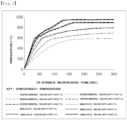
- FIG. 2 is a graph illustrating feasibility of the above-mentioned heating analysis technology and illustrating a comparison between heating analysis experimental values and analysis values under various furnace atmospheric temperature conditions for an aluminum plated material having a thickness of 1.2 mm.
- the analysis value is a result obtained by predicting such a condition using the above-mentioned analysis technique. As can be seen from FIG. 2 , it can be confirmed that the analysis value expresses the experimental value well.
- the present inventors analyzed a temperature rise pattern in various conditions to find out that a temperature rise pattern of a material is dependent on a thickness of the material, an atmospheric temperature, a maintaining time for each temperature zone, and the like.
- the present inventors found that the thickness of the material, an atmospheric temperature, a time required to stay at each atmospheric temperature are important in order to prevent a time required for staying in a high atmospheric temperature zone from excessively increasing and to avoid inability, to obtain a rapid heating effect, caused by a significantly short time required to stay in a high atmospheric temperature zone. Therefore, the present inventors have completed the present disclosure based on the fact that it is necessary to select an appropriate maintaining time depending on the thickness of the material and the atmospheric temperature. This will be described in detail below.
- the heating in section A may satisfy conditions specified by a figure ⁇ abcde' having cumulative in-furnace maintaining times and in-furnace atmospheric temperature coordinates of approximately a (0.2 min, 750°C), b(1.0min, 750°C), c(1.0min, 800°C), d(1.5min, 900°C), and e(0.2 min, 900°C).
- an atmospheric temperature in the furnace in section A may be set to, in detail, a range of about 750°C to about 900°C.
- the initial temperature rising rate may be significantly reduced to deteriorate productivity.
- the atmospheric temperature in the heating furnace in section A is set to higher than about 900°C, an initial region of the heating furnace is maintained at a high temperature to increase power consumption.
- the maintaining time in section A may be set to be short when the atmospheric temperature of section A is low and may be set to be long when the atmospheric temperature of section A is high.
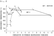
- the present inventors have intensively examined a preferable in-furnace atmospheric temperature and a preferable maintaining time for the heating in section A to find out that conditions of section A are preferably set as illustrated in FIG. 3 .
- the atmospheric temperature of section A is a low temperature of about 750°C
- the maintaining time of section A may be set to be short, in detail, about 1 minute or less.
- the maintaining time may be set to be, in detail, about 1.5 minutes or less. Meanwhile, the maintaining time in section A may be about 0.2 minute or more in consideration of a time of passing through an entrance side of the heating furnace.
- the thickness of the material may also have an effect.
- the maintaining time may be set in section A, irrespective of the thickness of the material, from a practical point of view (see FIG. 5A ).
- the heating in section B may satisfy conditions specified by a figure ⁇ fghi' having cumulative in-furnace maintaining times and atmospheric temperature coordinates of approximately f 1.3 + t ⁇ 1.2 0.6 ⁇ 0.5 min , 930 ° C , g ( 3.8 + t ⁇ 1.2 0.6 ⁇ 0.5 min , 930°C), h 3.3 + t ⁇ 1.2 0.6 ⁇ 0.5 min , 960 ° C , and i 0.8 + t ⁇ 1.2 0.6 ⁇ 0.5 min , 960°C) .
- a unit of the coordinates of the figure 'fghi' is f(1.3[min]+ ⁇ (t[mm]-1.2[mm])/0.6[mm] ⁇ 0.5[min], 930[°C]), g(3.8[Min]+ ⁇ (t[mm]-1.2[mm])/0.6[mm] ⁇ 0.5[min], 930[°C]), h(3.3[min]+ ⁇ (t[mm]-1.2[mm])/0.6[mm] ⁇ 0.5[min], 960[°C]), i(0.8[min]+ ⁇ (t[mm]-1.2[mm])/0.6[mm] ⁇ 0.5[min], 960[°C]).
- the heating in section B is heating in a region of the heating furnace in which the atmospheric temperature is highest, and affects a temperature rising rate and a maximum temperature of the material in a high-temperature region.
- the atmospheric temperature of section B When the atmospheric temperature of section B is low, the maximum temperature is decreased and the temperature rising rate is decreased. Meanwhile, when the atmospheric temperature of section B is high, the maximum temperature is increased and the temperature rising rate is also increased. Therefore, the atmospheric temperature of section B may be preferably set as high as possible. However, when the atmospheric temperature of section B is too high, the material may be heated to a significantly high temperature to deteriorate weldability. Therefore, it may be necessary to set a preferable range.
- a section from a section having an atmospheric temperature of about 930°C or higher to a section having the highest atmospheric temperature is regarded as section B.
- a section subsequent from the section, having an atmospheric temperature lower than the highest atmospheric temperature is regarded as a section distinguished from section B.
- section B has a first section B having an atmospheric temperature of about 930°C and a second section B having an atmospheric temperature of about 950°C and has a subsequent section having an atmospheric temperature of about 935°C
- a section subsequent from the section having the atmospheric temperature of about 935°C, an atmospheric temperature condition lower than the highest atmospheric temperature of about 950°C may be regarded as section C.
- the atmospheric temperature of section B may be set to a range of about 930°C to about 960°C.
- the atmospheric temperature of section B is higher than about 960°C, there is a limitation of furnace equipment, but weldability may be deteriorated because the temperature is set to be significantly high in terms of alloying of a plating layer.
- the temperature rising rate may be significantly reduced to increase a time required to reach a target temperature and to deteriorate productivity due to an increase in cycle time.
- section B not only the atmospheric temperature but also maintaining time of section B affects a temperature rising rate of a material and a maximum heating temperature of the material. For example, when the maintaining time of section B is too short, a sufficient temperature rising effect may not be obtained. In addition, when the maintaining time of section B is too long, the material may be maintained at a high temperature for a too long period of time to cause excessive alloying. Thus, the thickness of the diffusion layer may be increased to deteriorate weldability.
- a lower limit of the maintaining time in section B may be about 0.5 minute or more such that an effect of improving productivity is obtained by a high temperature rising rate.
- an upper limit of the maintaining time in section B may be about 4.8 minutes to prevent poor weldability caused by excessive alloying.
- the maintaining time of section B refers to a time for which the material is maintained in only section B, and is conceptually distinguished from the cumulative in-furnace maintaining time to be described later.
- Cumulative in-furnace maintaining time to section B may also affect the temperature rising rate of the material and the maximum heating temperature of the material in a high-temperature region. To increase the temperature to a sufficient temperature, the cumulative in-furnace maintaining time should be set to be long until the end of section B when the atmospheric temperature of section B is low and may be set to be short when the atmospheric temperature of section B is high.
- the cumulative in-furnace maintaining time refers to a cumulative in-furnace maintaining time until the end of section B, rather than a cumulative in-furnace maintaining time of section B itself.
- the cumulative in-furnace maintaining time in section B refers to a cumulative maintaining time, including all in-furnace heating maintaining times precedent to section B, for which heating is performed in the furnace until the end of section B (for example, the cumulative in-furnace maintaining time in section B refers to an in-furnace maintaining time in section A and section B when there is only section A before section B.
- the cumulative in-furnace maintaining time in section B refers to an in-furnace cumulative time including section A, the second B, and an additional section when the additional section is present between section A and section B).
- the cumulative maintaining time is important for the following reasons. For example, when the maintaining time of section A is short, the maintaining time of section B itself should be slightly long such that the temperature is increased to a sufficient temperature. Meanwhile, when the maintaining time of section A is long, the maintaining time of section B itself may be slightly short. For example, to achieve improved productivity through reduction of the heating time, a purpose of the present disclosure, it is necessary to consider not only the maintaining time of section B itself but also a time before section B.
- the B section is aimed at rapid temperature rise, and avoiding staying at the high temperature of section B for a long period of time by increasing the maintaining time of section B is preferable in terms of weldability while obtaining the same temperature rising effect. Therefore, when the effect of the material thickness is not considered based on such a result (for example, based on the material thickness of 1.2 mm), cumulative in-furnace maintaining time to section B may be maintained to a maximum of 3.8 minutes or less when a temperature of section B is about 930°C.
- a heating pattern of the material is dependent on the thickness of the material. Accordingly, the present inventors made an analysis of temperature rise on various thicknesses to find out that it is necessary to adjust a cumulative in-furnace maintaining time to section B according to a thickness, as illustrated in FIG. 5B .
- the cumulative in-furnace maintaining time to section B may have a range to be proportionally increased by about 0.5 minute as the thickness of the material is increases by 0.6 mm on the basis of the range specified by the figure 'fghi' of the material having a thickness of 1.2 mm in FIG. 3 .
- the cumulative in-furnace maintaining time to section B may have a range to be proportionally decreased by about 0.5 minute as the thickness of the material is decreased by 0.6 mm.
- a heating atmospheric temperature of section B may be set under optimized conditions based on the case, in which a material has a thickness t of 1.5 mm, in consideration of an effect on the thickness of the material.
- the atmospheric temperature of section B may be more than about 930°C to less than about 940°C.
- Section B should be set to a high atmospheric temperature to obtain a rapid temperature rise of the material, but heating may be performed at an atmospheric temperature, which is not too high, in consideration of a slight change in in-furnace maintaining time resulting from a work abnormality action in the actual production industry. Accordingly, when the thickness of the material is 1.5 mm or less, it is most advantageous, in terms of significantly reducing possibility of poor weldability, to control the atmospheric temperature of section B within the above-described range.
- the atmospheric temperature of section B may be, in more detail, more than about 930°C to less than about 935°C and, in most detail, about 931°C to 934°C.
- an effect of significantly reducing poor weldability may be further improved.
- the atmospheric temperature of section B may be more than about 930 °C to less than about 950 °C.
- Section B should be set to a high atmospheric temperature to obtain a rapid temperature rise of the material, but heating may be performed at an atmospheric temperature, which is not too high, in consideration of a slight change in in-furnace maintaining time resulting from a work abnormality action in the actual production industry. Accordingly, when the thickness of the material is greater than 1.5 mm, it is most advantageous, in terms of significantly reducing possibility of poor weldability, to control the atmospheric temperature of section B within the above-described range.
- the temperature of section B should be slightly higher than a temperature of a thin material.
- the atmospheric temperature of section B may be, in more detail, more than about 930°C to less than about 945°C and, in most detail, about 931°C to 940°C.
- weldability may be further improved.
- the atmospheric temperature of section B may be controlled to be more than about 940°C to 960°C or less from a standpoint of improving productivity by a rapid temperature rise and bendability.
- overall cumulative in-furnace maintaining time is preferably not too short, that is, as long as possible.
- the in-furnace maintaining time is preferably short from a viewpoint of productivity. Therefore, to satisfy both productivity and bendability, the temperature of section B may be increased to secure a rapid temperature rise, so that a more stable austenite structure may be secured in a heating process without increasing the overall cumulative maintaining time. As a result, more excellent bendability may be secured.
- a maximum atmospheric temperature Tb (for example, a maximum atmosphere maintaining temperature) of section B may be about 938°C or less, in more detail, about 935°C or less, and, in most detail, about 934°C or less.
- Tb for example, a maximum atmosphere maintaining temperature
- Heating in section C satisfies conditions specified by a figure 'jklm' having cumulative in-furnace maintaining times and atmospheric temperature coordinates of approximately j 3.7 + t ⁇ 1.2 0.6 min , 870 ° C , k 11.7 + t ⁇ 1.2 0.6 ⁇ 2 min , 870 ° C , l 7.03 + t ⁇ 1.2 0.6 ⁇ 2 min , 940 ° C , and m 2.53 + t ⁇ 1.2 0.6 min , 940 ° C .
- a highest atmospheric temperature (for example, a maximum atmosphere maintaining time) in section C is lower than a highest atmospheric temperature (for example, a maximum atmosphere maintaining time) in section B.
- an atmospheric temperature and a cumulative in-furnace maintaining time during heating in section C satisfy the conditions specified by a figure 'jklm' by including even an effect of the thickness of the material, and thus, both excellent productivity and weldability may be implemented.
- a unit of the coordinates of the figure 'jklm' is j(3.7[min]+ ⁇ (t[mm]-1.2[mm])/0.6[mm] ⁇ [min], 870[°C]), k(11.7[min]+ ⁇ (t[mm]-1.2[mm])/0.6[mm] ⁇ 2[min], 870[°C]), l(7.03[min]+ ⁇ (t[mm]-1.2[mm])/0.6[mm] ⁇ 2[min], 940[°C]), m(2.53[min]+ ⁇ (t[mm]-1.2[mm])/0.6[mm] ⁇ [min], 940[°C]).
- the heating in the C section affects a final maintaining temperature of the material.
- a maximum atmospheric temperature of section C is set to be lower than the maximum atmospheric temperature of section B. This is because, when the atmospheric temperature of section C is as high as in section B, the material is heated at a high temperature for a long period of time to deteriorate weldability.
- the heating in section B is set to a high temperature because it is mainly aimed at increasing the temperature rising rate of the material
- the heating in section C is preferably set to a temperature, which is not too high or low, because it is aimed at controlling the final maintaining temperature of the material.
- section C When the atmospheric temperature of section C is set to less than about 870°C, a material take-out temperature is significantly low, so that it may be cooled to a significantly low temperature in subsequent conveying and pre-forming cooling operations to significantly decrease a temperature during the forming. As a result, formability may be deteriorated.
- the atmospheric temperature of section C may be lower than the atmospheric temperature of section B in terms of improving weldability.
- the atmospheric temperature of section C may be set to be lower than a lowest atmospheric temperature (for example, a lowest atmosphere maintaining temperature) in section B.
- a lowest atmospheric temperature for example, a lowest atmosphere maintaining temperature
- section C is about 870°C or higher but may be set to lower than about 930°C (for example, less than 930°C), the first section B.
- the maximum atmospheric temperature of section C may be set to about Tb-20°C or less based on the maximum atmospheric temperature Tb of section B, or may be set to a range of about Tb-30°C or less (in this case, the maximum atmospheric temperature refers to a maximum atmosphere maintaining temperature, as described above).
- the greater a difference in temperatures between section B and section C the greater an effect of improving weldability due to a rapid temperature rise and suppression of an increase in the thickness of the diffusion layer.
- the temperature of section B should be increased while the temperature of section C should be decreased. Therefore, a range is significantly narrowed in terms of setting work conditions and it takes significantly long time to reach a temperature to section C.
- the present inventors confirmed that, when the difference in temperatures between section B and section C is about 20°C, the material reaches the temperature of section C within a short period of time (for example, about 30 seconds or less). Accordingly, the difference in temperatures between section B and section C is, in most detail, about 20°C or more and section C is, in most detail, about 870°C or more.
- the cumulative in-furnace maintaining time until the end of section C also affects the final maintaining temperature.
- the cumulative in-furnace maintaining time until the end of the C section should be set to be long.
- the cumulative in-furnace maintaining time until the end of section C may be set to be short.
- the cumulative in-furnace maintaining time until the end of section C also refers to a cumulative in-furnace maintaining time until section C, rather than a maintaining time of section C itself. In this case, the above descriptions may be equally applied to the cumulative in-furnace maintaining time.
- the cumulative maintaining time is important for the following reasons. For example, when the in-furnace maintaining time just before the C section is short, the maintaining time of section C itself needs to be slightly long for sufficient alloying. Meanwhile, when the in-furnace maintaining time just before section C is long, it is necessary to consider that the maintaining time of section C itself may be somewhat short. For example, although improvement of productivity, the purpose of the present disclosure, is implemented, not only the maintaining time of section C itself but also a time before section C needs to be considered for sufficient alloying. The cumulative in-furnace maintaining time until the end of section C was derived by analyzing various embodiments to be described in detail later.
- the cumulative in-furnace maintaining time until the end of section C may be about 3.7 to 11.7 minutes when an atmospheric temperature is about 870°C and may be about 2.53 to 7.03 minutes when an atmospheric temperature is about 940°C.
- the atmospheric temperature of section C is high, when the cumulative in-furnace maintaining time until the end of section C is too long, heating time may be significantly increased to deteriorate productivity and weldability.
- the overall cumulative in-furnace maintaining time to section C should be increased to compensate for the low atmospheric temperature of section C.
- a temperature rising pattern of the material in section C is dependent on the thickness of the material. Therefore, the present inventor made an analysis of temperature rise on various thicknesses to confirm that it was necessary to adjust the cumulative in-furnace maintaining time until the end of section C depending on a thickness, as illustrated in FIG. 5C .
- the cumulative in-furnace maintaining time until the end of section C may have a range in which a minimum maintaining time is proportionally increased by one minute and a maximum maintaining time is proportionally increased by two minutes as the thickness of the material is increases by 0.6 mm on the basis of the range specified by the figure 'jklm' of the material having a thickness of 1.2 mm in FIG. 3 .
- the cumulative in-furnace maintaining time until the end of section C may have a range in which a minimum maintaining time is proportionally decreased by one minute and a maximum maintaining time is proportionally decreased by two minutes as the thickness of the material is decreased by 0.6 mm.
- the present disclosure may meet the cumulative in-furnace maintaining time and atmospheric temperature specified by the figure 'jklm' reflecting even the above-described effect of thickness.
- the heating in section C may be performed at an atmospheric temperature of about 935°C or less, in more detail, at an atmospheric temperature of about 930°C or less.
- a maximum atmospheric temperature for example, a maximum atmosphere maintaining temperature
- productivity and weldability may be further improved.
- the maintaining time in section C may be about 0.5 minutes or more.
- the maintaining time in section C is less than about 0.5 minutes, it may not reach a final maintaining temperature, but the preset disclosure is not limited thereto.
- the atmospheric temperature of section C may be about 870°C or more to less than 880°C. This is because since alloying of the plating layer is performed significantly more rapidly when the material is maintained at a high temperature during heating, it is most advantageous, in terms of weldability, to maintain the temperature of section C, the final maintaining temperature, at about 870°C or more to less than 880°C.
- the atmospheric temperature of section C when the thickness t is greater than 1.5 mm, the atmospheric temperature of section C may be about 870°C or more to less than 900°C. This is because since alloying of the plating layer is performed significantly more rapidly when the material is maintained at a high temperature during heating, it is most advantageous, in terms of weldability, to maintain the temperature of section C, the final maintaining temperature, at about 870°C or more to less than 900°C when the thickness of the material is greater than 1.5 mm. This takes into account the fact that, when the thickness of the material is increased, the temperature of section C should be slightly higher than a temperature of a thin material.
- the maintaining time in each of section B and section C may be, in detail, about 0.5 minute to obtain an effect that the present disclosure desires.
- the maintaining time in each of section B and section C refers to maintaining time of each of section B itself and section C itself, rather than cumulative time.
- the maintaining time in at least one of section B and section C is less than about 0.5 minutes, it may be difficult to expect effects of rapid temperature rise in section B and reaching a low final maintaining temperature in section C, but the present disclosure is not necessarily limited thereto.
- the heating operation may be performed such that a value of the following Relational Expression 2 satisfies 2 or more.
- a value of Relational Expression 2 is an empirical value, a unit is not necessarily determined.
- T n denotes a heating furnace atmospheric temperature in an n-th section in a conveying direction of a blank and a unit thereof is degrees Celsius (°C)
- t n denotes a heating furnace maintaining time in the n-th section in the conveying direction of the blank and a unit thereof is minute
- t total denotes total maintaining time in the heating furnace and a unit thereof is minute
- x denotes the number of sections maintained at a specific atmospheric temperature in the heating furnace
- k is an integer of 3 in the case of a final section in section B, an integer of -1 in the case in which a section subsequent to section B,
- the n-th section in the heating furnace refers to a section maintained at a specific atmospheric temperature, and refers to a section present in n-th in the conveying direction of the blank.
- the respective sections, present in the conveying direction of the blank may be divided by atmospheric temperature.
- the furnace maintaining time in the n-th section refers to maintaining time of each section itself, rather than cumulative maintaining time in the heating furnace.
- the maintaining time in each section may refer to maintaining time in each heating zone corresponding to each section in a heating furnace, including a plurality of heating zones described above, in which atmospheric temperatures in the heating zones may be controlled to be distinguished from each other.
- time for which the material is maintained in the single heating zone may refer to time from a point in time at which a blank, a material, is injected to a point in time at which the blank is removed of the single heating zone.
- section B refers to a section from a section having an atmospheric temperature of about 930°C or more to a section having a highest atmospheric temperature
- a final section of section B refers to a section having the highest atmospheric temperature (for example, highest atmosphere maintaining temperature).
- the term "a section subsequent to section B" refers to a section, present and distinguished by a heating furnace atmospheric temperature after section B in the conveying direction of the blank, except for section B.
- section A atmospheric temperature: T1, maintaining time: t1
- section B atmospheric temperature: T2, maintaining time: t2
- a first section C atmospheric temperature: T3, maintaining time: t3
- a second section C atmospheric temperature: T4, maintaining time: t4 .
- the above-described Relational Expression 2 may be [ ⁇ (T1-870) ⁇ t1/t total ⁇ 0.1334 ⁇ 1 ⁇ + ⁇ (T2-870) ⁇ t2/t total ⁇ 0.1334 ⁇ 3 ⁇ + ⁇ (T3-870) ⁇ t3/t total ⁇ 0.1334 ⁇ (-1) ⁇ + ⁇ (T4-870) ⁇ 14/t total ⁇ 0.1334 ⁇ (-1 ) ⁇ ]/t.
- the present inventors have made an intensive examination of patterns of temperature and time of the heating furnace during a heating process to conduct additional research into a method of further improving shape precision of a product, in addition to productivity, weldability, and formability.
- the present inventors conducted research into an effect on a formed member based on a value V cal , obtained by multiplying a ratio of time occupied by each section in the overall process by a difference in the heating atmospheric temperature based on 870°C, and 0.1334.
- the value V cal is preferably large in terms of productivity in a section before a section maintained at the highest atmospheric temperature, the value V cal has a positive sign (+) (for example, k corresponds to +1) . Since an effect of the section maintained at the highest atmospheric temperature is greatest, the value Vcal is affected by (+3) times (for example, k corresponds to an integer of 3).
- the value Vcal is preferably small to reduce a thickness of a diffusion layer in terms of weldability in a section subsequent to section B, the value Vcal has a negative sign (-) .
- the present inventor found that by satisfying the value of Relational Expression 2 or more, obtained by dividing the sum of the values V cal in the respective sections by t in consideration of an effect of a thickness, it could reduce warpage of a product when the product was removed of a combination of furnace sections having appropriate conditions and was then cooled in air.
- weldability, and formability shape precision of the product may be further improved.
- a heated blank is removed of a heating furnace, and then conveyed to a mold mounted on a press.
- the blank is cooled by air cooling during such a conveying process .
- a blank supply jig evades within a process working range, and then a press slide begins to descend.
- An upper mold portion starts to be in contact with the blank after a predetermined time elapses. Forming process is substantially started after the upper mold portion is in contact with the seated blank. As describe above, a certain time is required before forming process is performed after blank is seated.
- the blank is air-cooled overall and is brought into contact with a structure such as a lifter, supporting a lower mold portion or a blank of the lower mold portion, so that quenching occurs in the contact portion.
- a structure such as a lifter, supporting a lower mold portion or a blank of the lower mold portion, so that quenching occurs in the contact portion.
- the present inventors found that not only time required for a conveying process, in which air cooling mainly occurs, but also time required before forming is performed after the blank is seated needs to be significantly reduced to secure overall safe formability. Since it is well known that quenching is important in securing physical properties in a state in which the mold is completely in close contact therewith after forming is finished, an additional description of the quenching will be omitted. In the present disclosure, the following analysis was made because the present inventors found that it is important to manage cooling time during conveying and time required before forming is performed after the blank is seated, in terms of securing physical properties and formability.
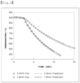
- FIG. 6 is a graph illustrating a comparison between experimental values and analysis values for temperature changes depending on times for which an aluminum plating material having a thickness of 0.9 mm and an aluminum plating material having a thickness of 1.8 mm are cooled in air after they are extracted from a heating furnace. As can be seen from FIG. 6 , the analysis values predict the experimental values well.
- Relational Expression 1 is an empirically obtained value, a unit may not be necessarily determined, and it is sufficient as long as the unit of T is second (s), the unit of t is millimeters (mm), and the unit of temp is degrees Celsius (°C).
- T may be greater than about 10 seconds, in more detail, about 11 seconds or more.
- T may be greater than about 10 seconds, in more detail, about 11 seconds or more.
- the present disclosure may be applied to even equipment including a conveying device having slightly low speed. Accordingly, since unnecessary equipment investment in not required, economical feasibility may be secured.
- a thickness t of a material may range from about 0.6 to about 2.6mm.
- the thickness t of the material is less than about 0.6mm, the material is significantly thin, causing sagging, or the like, to occur in a continuous heating furnace during conveying. Meanwhile, when the thickness t of the material is greater than about 2.6 mm, the material is too thick to easily manufacture an aluminum plating material.
- cooling includes air cooling during a conveying process and cooling by a lower mold portion before forming is performed after a blank is seated.
- a portion in contact with a structure such as a lifter, supporting a lower mold portion or a blank of the lower mold portion is cooled more rapidly than a non-contact and air-cooled portion. Therefore, the present inventor found that in terms of air cooling of the entire blank, it is sufficient to satisfy only Relational Expression 1-1 [T ⁇ 8.2 ⁇ t], but it is important to suppress an increase in the time required before forming is performed after the blank is seated on the lower mold portion and is then brought into contact with an upper mold portion.
- the time required before forming is performed after the blank is seated may be 2 seconds or less.
- the present inventors observed temperatures of a portion in contact with the lifter under a condition in which the blank is conveyed for eight seconds and is brought into contact with a lower lifter for one second, a condition in which the blank is conveyed for seven seconds and is brought into contact with the lower lifter for two seconds, and a condition in which the blank is conveyed for six seconds and is brought into contact with the lower lifter for three seconds.
- a portion of the blank in contact with the lower mold portion of the mold may be cooled to a temperature level of 650 °C determined to be unable to work in management of a conventional hot press forming process. Accordingly, there is possibility that the blank is scrapped without performing a forming operation.
- the time required before forming is performed after the blank is seated may be controlled to be, in most detail, two seconds or less while performing a process to satisfy Relational Expression 1 before the heated blank is brought into contact with the upper mold portion to start forming.
- a thickness of a plating layer of the blank may be 20 pm or more.
- the thickness of the plating layer of the blank is less than 20 ⁇ m, heating may be performed while the plating layer of the blank is thin, and alloying may be rapidly performed to allow the diffusion layer to be more rapidly increased.
- the thickness of the plating layer of the blank may be controlled to be, in detail, 20 pm or more.
- the thickness of the plated layer of the blank may be, in more detail, 25 um or more, and thus, an increase in the thickness of the diffusion layer may be suppressed to further improve weldability.
- an upper limit of the thickness of the plating layer of the blank is not necessarily limited, it may be 33 um or less, a thickness widely applied in industry, because an alloying rate of the plating layer may be reduced.
- a thickness of a diffusion layer of the formed member may be 15 um or less. Since the diffusion layer has high resistance due to poor conductivity, local heat generation occurs significantly during welding when the diffusion layer is too thick, so that spatter may occur. Therefore, the thickness of the diffusion layer may be controlled to be, in detail, 15 um or less.
- the diffusion layer of the formed member may refer to a layer including an intermetallic compound of Fe and Al, and examples of the intermetallic compound of Fe and Al may be FeAl, Fe 3 Al, and the like.
- the diffusion layer of the formed member may further include some components among components derived from the plating layer.
- a thickness of an alloy layer of the formed member may be 27 to 50 um.
- the thickness of the alloy layer of the formed member is less than 27 ⁇ m, corrosion resistance may be insufficient.
- the thickness of the alloy layer is more than 50 ⁇ m, there is a possibility that seizure of the plating layer may occur intensively in the mold during forming. From the standpoint of further improving the above-described effect, the thickness of the alloy layer of the formed member may be, in more detail, 35 to 50 um.
- the thickness of the alloy layer of the formed member refers to overall thickness of coating including the diffusion layer.
- a ratio of the thickness of the diffusion layer of the formed member to the thickness of the alloy layer of the formed member may be 0.5 or less, in more detail, 0.33 or less.
- the above-described conditions may be satisfied to prevent weldability from being deteriorated by spatter occurring as the thickness of the diffusion layer is significantly increased, as compared to the thickness of the alloy layer of the formed member.
- a plated steel sheet was obtained by dipping a base steel sheet in a plating bath Al-Si9%-Fe3%.
- the base steel sheet comprised, by weight percentage (wt%), 0.22% of carbon (C), 0.3% of silicon (Si), 1.2% of manganese (Mn), 0.2% of chromium (Cr), 0.03% of aluminum (Al), 0.01% of phosphorus (P), 0.001% of sulfur (S), N: 0.003% of nitrogen (N), 0.003% of boron (B), and a balance of iron (Fe) and unavoidable impurities.
- a blank was heated in a heating furnace to satisfy conditions listed in Tables 1 and 2 below, conveyed between an upper mold portion and a lower mold portion of a mold, and then cooled by seating the lower mold, formed and removed to manufacture a hot press-formed member.
- atmosphere maintaining temperatures in the respective zones were measured using thermocouple to list an atmosphere maintaining temperature in each section of Table 1 below.
- the maintaining time in each section was listed in Table 1 below by measuring a time from a point in time, at which the blank, a material, is charged, to a point in time at which the blank is removed, based on each heating zone corresponding each section.
- cumulative maintaining time in each section was listed in Table 1 below by measuring the point in time, at which the blank, a material, is injected into the heating furnace, to a point in time at which the blank, a material, is removed from each heating zone corresponding to each heating furnace.
- Weldability was classified as follows, based on a welding current range value during resistance welding (a range value between a minimum current value, at which a minimum nugget diameter may be secured, and a maximum current value at which spatter occurs).
- a welding current range used a correlation equation between a thickness of a diffusion layer and the welding current range.
- Formability was classified as follows, based on a blank temperature of 650°C before forming, a criterion of management for suppressing occurrence of defective products.
- Productivity was evaluated by performing classification as follows, based on a time at which a thickness of a diffusion layer, regulated to secure physical properties by an automobile company, is 15 um.
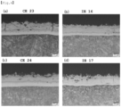
- Comparative Example 24 not satisfying the above-described heating conditions in the heating furnace and the above-described cooling conditions by a lower mold portion, it was confirmed that productivity, weldability, and formability were all deteriorated.
- Inventive Example 18 satisfying all conditions that a thickness of a plating layer of a blank was 20 um or more, a thickness of a diffusion layer thickness of a formed member was 15 pm or less, a thickness of an alloy layer of the formed member was 27 to 50 um, and a ratio of the thickness of the diffusion layer of the formed member to the thickness of the alloy layer of the blank (thickness of diffusion layer/thickness of alloy layer) was 0.33 or less, it was confirmed that weldability was improved, as compared to Inventive Example 19, not satisfying at least one of the above conditions.
- productivity was evaluated based on the following criteria depending on whether the temperature of the material reached a furnace take-up temperature.
- Bendability was evaluated using a three-point bending test, and a bending angle was measured when a maximum load occurred, and thus, classification was performed based on the following criteria.
- a method of manufacturing a hot press-formed member having improved weldability and formability may be provided.
Landscapes
- Chemical & Material Sciences (AREA)
- Engineering & Computer Science (AREA)
- Mechanical Engineering (AREA)
- Organic Chemistry (AREA)
- Materials Engineering (AREA)
- Metallurgy (AREA)
- Thermal Sciences (AREA)
- Physics & Mathematics (AREA)
- Crystallography & Structural Chemistry (AREA)
- Chemical Kinetics & Catalysis (AREA)
- Oil, Petroleum & Natural Gas (AREA)
- Shaping Metal By Deep-Drawing, Or The Like (AREA)
- Coating With Molten Metal (AREA)
- Heat Treatment Of Articles (AREA)
- Control Of Heat Treatment Processes (AREA)
- Heat Treatments In General, Especially Conveying And Cooling (AREA)
Applications Claiming Priority (3)
| Application Number | Priority Date | Filing Date | Title |
|---|---|---|---|
| KR20200085533 | 2020-07-10 | ||
| KR1020200101357A KR102240850B1 (ko) | 2020-07-10 | 2020-08-12 | 생산성, 용접성 및 성형성이 우수한 열간 프레스 성형 부재의 제조 방법 |
| PCT/KR2020/011662 WO2022010030A1 (ko) | 2020-07-10 | 2020-08-31 | 생산성, 용접성 및 성형성이 우수한 열간 프레스 성형 부재의 제조 방법 |
Publications (2)
| Publication Number | Publication Date |
|---|---|
| EP4180146A1 true EP4180146A1 (de) | 2023-05-17 |
| EP4180146A4 EP4180146A4 (de) | 2023-05-31 |
Family
ID=75743518
Family Applications (1)
| Application Number | Title | Priority Date | Filing Date |
|---|---|---|---|
| EP20944436.3A Pending EP4180146A4 (de) | 2020-07-10 | 2020-08-31 | Verfahren zur herstellung eines heisspressgeformten elements mit hervorragender produzierbarkeit, schweissbarkeit und formbarkeit |
Country Status (7)
| Country | Link |
|---|---|
| US (2) | US11590549B2 (de) |
| EP (1) | EP4180146A4 (de) |
| JP (2) | JP7558380B2 (de) |
| KR (3) | KR102240850B1 (de) |
| CN (1) | CN113909322B (de) |
| MX (2) | MX2025012896A (de) |
| WO (1) | WO2022010030A1 (de) |
Cited By (2)
| Publication number | Priority date | Publication date | Assignee | Title |
|---|---|---|---|---|
| EP4260960A4 (de) * | 2020-12-09 | 2025-01-22 | Hyundai Steel Company | Heissgeprägte komponente und verfahren zur herstellung davon |
| EP4424434A4 (de) * | 2021-10-29 | 2025-12-31 | Hyundai Steel Co | Heissgeprägte teile und herstellungsverfahren dafür |
Families Citing this family (1)
| Publication number | Priority date | Publication date | Assignee | Title |
|---|---|---|---|---|
| DE102023105207A1 (de) * | 2023-03-02 | 2024-09-05 | Thyssenkrupp Steel Europe Ag | Verfahren zum Warmpressformen mit verbesserten Eigenschaften |
Family Cites Families (18)
| Publication number | Priority date | Publication date | Assignee | Title |
|---|---|---|---|---|
| JP3863874B2 (ja) | 2003-10-02 | 2006-12-27 | 新日本製鐵株式会社 | 金属板材の熱間プレス成形装置及び熱間プレス成形方法 |
| EP4023433A1 (de) | 2006-10-30 | 2022-07-06 | ArcelorMittal | Beschichtete stahlbänder, verfahren zur herstellung davon, verfahren zur verwendung davon, daraus hergestellte stanzzuschnitte, daraus hergestellte gestanzte produkte und erzeugnisse, die solch ein gestanztes produkt enthalten |
| WO2009090443A1 (en) * | 2008-01-15 | 2009-07-23 | Arcelormittal France | Process for manufacturing stamped products, and stamped products prepared from the same |
| MX2011000056A (es) | 2008-07-11 | 2011-04-27 | Nippon Steel Corp | Lamina de acero chapada con aluminio para prensado en caliente con calentamiento rapido, proceso para producir la misma, y metodo para prensar en caliente la misma con calentamento rapido. |
| JP5304678B2 (ja) * | 2010-02-09 | 2013-10-02 | 新日鐵住金株式会社 | 熱間プレス方法、および成形品の製造方法 |
| KR101033361B1 (ko) * | 2010-06-30 | 2011-05-09 | 현대하이스코 주식회사 | 생산성을 향상시킨 열간 프레스 성형체 제조방법 |
| DE102010048209C5 (de) * | 2010-10-15 | 2016-05-25 | Benteler Automobiltechnik Gmbh | Verfahren zur Herstellung eines warmumgeformten pressgehärteten Metallbauteils |
| US20150352621A1 (en) | 2013-01-11 | 2015-12-10 | Futaba Industrial Co., Ltd. | Heating device for hot stamping |
| KR101482395B1 (ko) * | 2013-04-19 | 2015-01-13 | 주식회사 포스코 | 도금 강재의 열간 프레스 성형 장치 및 이를 이용한 성형 방법 |
| JP5825413B1 (ja) | 2014-04-23 | 2015-12-02 | Jfeスチール株式会社 | 熱間プレス成形品の製造方法 |
| HUE042089T2 (hu) | 2015-10-15 | 2019-06-28 | Automation Press And Tooling A P & T Ab | Részleges sugárzással való hevítési módszer az alakítva edzett alkatrészek gyártásához és a gyártási eljárás kialakításához |
| KR101819345B1 (ko) * | 2016-07-07 | 2018-01-17 | 주식회사 포스코 | 균열전파 저항성 및 연성이 우수한 열간성형 부재 및 이의 제조방법 |
| WO2018115914A1 (en) | 2016-12-19 | 2018-06-28 | Arcelormittal | A manufacturing process of hot press formed aluminized steel parts |
| CN108588612B (zh) * | 2018-04-28 | 2019-09-20 | 育材堂(苏州)材料科技有限公司 | 热冲压成形构件、热冲压成形用预涂镀钢板及热冲压成形工艺 |
| CN109518114A (zh) * | 2018-08-08 | 2019-03-26 | 宝山钢铁股份有限公司 | 带铝硅合金镀层的热冲压部件的制造方法及热冲压部件 |
| CN110180957B (zh) * | 2018-06-28 | 2020-11-03 | 镕凝精工新材料科技(上海)有限公司 | 一种镀锌钢板的热处理方法及热冲压工艺 |
| KR20200076071A (ko) * | 2018-12-19 | 2020-06-29 | 주식회사 포스코 | 열간 성형용 알루미늄 도금강재의 가열 방법 |
| KR102201434B1 (ko) * | 2018-12-27 | 2021-01-12 | 현대제철 주식회사 | 핫 스탬핑 부품 제조장치 및 이를 이용한 핫 스탬핑 부품 제조방법 |
-
2020
- 2020-08-12 KR KR1020200101357A patent/KR102240850B1/ko active Active
- 2020-08-31 JP JP2023501479A patent/JP7558380B2/ja active Active
- 2020-08-31 EP EP20944436.3A patent/EP4180146A4/de active Pending
- 2020-08-31 WO PCT/KR2020/011662 patent/WO2022010030A1/ko not_active Ceased
- 2020-09-01 US US17/008,827 patent/US11590549B2/en active Active
- 2020-09-02 CN CN202010911953.9A patent/CN113909322B/zh active Active
-
2021
- 2021-01-11 MX MX2025012896A patent/MX2025012896A/es unknown
- 2021-01-11 MX MX2021000379A patent/MX2021000379A/es unknown
- 2021-04-09 KR KR1020210046569A patent/KR102876450B1/ko active Active
-
2023
- 2023-01-19 US US18/098,945 patent/US12528111B2/en active Active
-
2024
- 2024-09-17 JP JP2024159923A patent/JP7755020B2/ja active Active
-
2025
- 2025-10-21 KR KR1020250152925A patent/KR20250159608A/ko active Pending
Cited By (2)
| Publication number | Priority date | Publication date | Assignee | Title |
|---|---|---|---|---|
| EP4260960A4 (de) * | 2020-12-09 | 2025-01-22 | Hyundai Steel Company | Heissgeprägte komponente und verfahren zur herstellung davon |
| EP4424434A4 (de) * | 2021-10-29 | 2025-12-31 | Hyundai Steel Co | Heissgeprägte teile und herstellungsverfahren dafür |
Also Published As
| Publication number | Publication date |
|---|---|
| US20220008978A1 (en) | 2022-01-13 |
| US11590549B2 (en) | 2023-02-28 |
| JP2023534207A (ja) | 2023-08-08 |
| KR102876450B1 (ko) | 2025-10-24 |
| MX2025012896A (es) | 2025-12-01 |
| US12528111B2 (en) | 2026-01-20 |
| CN113909322A (zh) | 2022-01-11 |
| WO2022010030A1 (ko) | 2022-01-13 |
| EP4180146A4 (de) | 2023-05-31 |
| KR102240850B1 (ko) | 2021-04-16 |
| US20230158559A1 (en) | 2023-05-25 |
| JP2025000702A (ja) | 2025-01-07 |
| CN113909322B (zh) | 2023-11-24 |
| KR20250159608A (ko) | 2025-11-11 |
| JP7558380B2 (ja) | 2024-09-30 |
| JP7755020B2 (ja) | 2025-10-15 |
| KR20220007503A (ko) | 2022-01-18 |
| MX2021000379A (es) | 2022-01-11 |
Similar Documents
| Publication | Publication Date | Title |
|---|---|---|
| US12528111B2 (en) | Method of manufacturing hot press-formed member having excellent productivity, weldability and formability | |
| TW558569B (en) | High tensile hot-rolled steel sheet having excellent strain aging hardening properties and method for producing the same | |
| TWI453300B (zh) | 熱壓用鋼板以及使用該熱壓用鋼板的熱壓部材的製造方法 | |
| JP7001197B2 (ja) | 鋼板、部材及びそれらの製造方法 | |
| TW201928085A (zh) | 鋁系鍍敷鋼板、鋁系鍍敷鋼板的製造方法及汽車用零件的製造方法 | |
| US20230321706A1 (en) | Steel strip and method of producing same | |
| JPWO2014051005A1 (ja) | 複合組織鋼板およびその製造方法 | |
| CN109642292A (zh) | 高强度钢板及其制造方法 | |
| CN111989424A (zh) | Ni扩散镀层钢板以及Ni扩散镀层钢板的制造方法 | |
| US20150376738A1 (en) | Titanium sheet | |
| JP7311068B1 (ja) | 亜鉛めっき鋼板および部材、ならびに、それらの製造方法 | |
| CN117836458A (zh) | 钢板、构件和它们的制造方法 | |
| EP2832884B1 (de) | Feuerverzinktes stahlblech zur pressformung mit ausgezeichneter kaltverformbarkeit, ausgezeichneter in-mold-härtbarkeit und ausgezeichneten oberflächeneigenschaften sowie verfahren zur herstellung davon | |
| CN113260721A (zh) | 钢板及其制造方法 | |
| CN113825846B (zh) | 生产连续铸造热轧高强度钢片产品的方法 | |
| US11560606B2 (en) | Methods of producing continuously cast hot rolled high strength steel sheet products | |
| US20260043105A1 (en) | Steel sheet having excellent powdering properties after press-hardening and method for manufacturing the same | |
| Chen et al. | Quench Rate Study on AA7075 with Advanced Aging and T6 | |
| US20260009115A1 (en) | Plated steel sheet for hot press forming having excellent surface properties and method for manufacturing same | |
| JP7662962B2 (ja) | 鋼板及びその製造方法 | |
| EP4640913A1 (de) | Aluminiumplattiertes stahlblech, heisspressformteil damit und herstellungsverfahren dafür | |
| JP2025095270A (ja) | 鋼板製造設備の制御方法および鋼板製造設備 | |
| JP2025532511A (ja) | アルミニウムめっき鋼板、それを用いた熱間成形部材及びそれらの製造方法 | |
| WO2025205979A1 (ja) | 鋼板、鋼帯およびそれらの製造方法 | |
| Lodwig | Hot dip coating of high strength low carbon steels |
Legal Events
| Date | Code | Title | Description |
|---|---|---|---|
| STAA | Information on the status of an ep patent application or granted ep patent |
Free format text: STATUS: THE INTERNATIONAL PUBLICATION HAS BEEN MADE |
|
| PUAI | Public reference made under article 153(3) epc to a published international application that has entered the european phase |
Free format text: ORIGINAL CODE: 0009012 |
|
| STAA | Information on the status of an ep patent application or granted ep patent |
Free format text: STATUS: REQUEST FOR EXAMINATION WAS MADE |
|
| 17P | Request for examination filed |
Effective date: 20230210 |
|
| AK | Designated contracting states |
Kind code of ref document: A1 Designated state(s): AL AT BE BG CH CY CZ DE DK EE ES FI FR GB GR HR HU IE IS IT LI LT LU LV MC MK MT NL NO PL PT RO RS SE SI SK SM TR |
|
| A4 | Supplementary search report drawn up and despatched |
Effective date: 20230502 |
|
| RIC1 | Information provided on ipc code assigned before grant |
Ipc: C22C 38/32 20060101ALN20230424BHEP Ipc: C22C 38/06 20060101ALN20230424BHEP Ipc: C22C 38/04 20060101ALN20230424BHEP Ipc: C22C 38/00 20060101ALN20230424BHEP Ipc: C21D 9/46 20060101ALN20230424BHEP Ipc: C22C 38/02 20060101ALN20230424BHEP Ipc: C21D 6/00 20060101ALN20230424BHEP Ipc: C21D 1/18 20060101ALN20230424BHEP Ipc: C21D 8/00 20060101ALI20230424BHEP Ipc: C22C 21/02 20060101ALI20230424BHEP Ipc: C23C 2/12 20060101ALI20230424BHEP Ipc: C21D 7/13 20060101ALI20230424BHEP Ipc: C21D 1/673 20060101ALI20230424BHEP Ipc: C23C 2/28 20060101ALI20230424BHEP Ipc: C21D 9/56 20060101ALI20230424BHEP Ipc: C23C 30/00 20060101ALI20230424BHEP Ipc: C23C 28/02 20060101AFI20230424BHEP |
|
| DAV | Request for validation of the european patent (deleted) | ||
| DAX | Request for extension of the european patent (deleted) |