EP4180108A1 - Procédé et dispositif de filtrage d'une suspension - Google Patents
Procédé et dispositif de filtrage d'une suspension Download PDFInfo
- Publication number
- EP4180108A1 EP4180108A1 EP21208017.0A EP21208017A EP4180108A1 EP 4180108 A1 EP4180108 A1 EP 4180108A1 EP 21208017 A EP21208017 A EP 21208017A EP 4180108 A1 EP4180108 A1 EP 4180108A1
- Authority
- EP
- European Patent Office
- Prior art keywords
- filter
- filtrate
- gas
- expulsion
- segments
- Prior art date
- Legal status (The legal status is an assumption and is not a legal conclusion. Google has not performed a legal analysis and makes no representation as to the accuracy of the status listed.)
- Pending
Links
- 238000000034 method Methods 0.000 title claims abstract description 29
- 239000000725 suspension Substances 0.000 title claims abstract description 22
- 238000001914 filtration Methods 0.000 title claims abstract description 20
- 239000000706 filtrate Substances 0.000 claims abstract description 206
- 239000012065 filter cake Substances 0.000 claims abstract description 43
- 238000007791 dehumidification Methods 0.000 claims abstract description 23
- 238000007599 discharging Methods 0.000 claims description 4
- 239000007789 gas Substances 0.000 description 76
- 230000015572 biosynthetic process Effects 0.000 description 8
- 239000007788 liquid Substances 0.000 description 4
- 239000007787 solid Substances 0.000 description 4
- 238000005273 aeration Methods 0.000 description 3
- 238000013461 design Methods 0.000 description 3
- 239000004744 fabric Substances 0.000 description 3
- 238000005192 partition Methods 0.000 description 3
- 239000000047 product Substances 0.000 description 3
- 230000000694 effects Effects 0.000 description 2
- 238000004519 manufacturing process Methods 0.000 description 2
- 230000000903 blocking effect Effects 0.000 description 1
- 238000007664 blowing Methods 0.000 description 1
- 230000001914 calming effect Effects 0.000 description 1
- 239000003638 chemical reducing agent Substances 0.000 description 1
- 230000000295 complement effect Effects 0.000 description 1
- 230000001419 dependent effect Effects 0.000 description 1
- 230000006866 deterioration Effects 0.000 description 1
- 230000002706 hydrostatic effect Effects 0.000 description 1
- 239000011261 inert gas Substances 0.000 description 1
- 229910052500 inorganic mineral Inorganic materials 0.000 description 1
- 238000012423 maintenance Methods 0.000 description 1
- 238000005259 measurement Methods 0.000 description 1
- 239000012528 membrane Substances 0.000 description 1
- 239000002184 metal Substances 0.000 description 1
- 239000011707 mineral Substances 0.000 description 1
- 238000012986 modification Methods 0.000 description 1
- 230000004048 modification Effects 0.000 description 1
- 239000002245 particle Substances 0.000 description 1
- 230000000149 penetrating effect Effects 0.000 description 1
- 230000035699 permeability Effects 0.000 description 1
- 238000012545 processing Methods 0.000 description 1
- 238000001228 spectrum Methods 0.000 description 1
- 239000000126 substance Substances 0.000 description 1
- 238000011144 upstream manufacturing Methods 0.000 description 1
- 238000009423 ventilation Methods 0.000 description 1
- 238000013022 venting Methods 0.000 description 1
- 239000002699 waste material Substances 0.000 description 1
Images


Classifications
-
- B—PERFORMING OPERATIONS; TRANSPORTING
- B01—PHYSICAL OR CHEMICAL PROCESSES OR APPARATUS IN GENERAL
- B01D—SEPARATION
- B01D33/00—Filters with filtering elements which move during the filtering operation
- B01D33/15—Filters with filtering elements which move during the filtering operation with rotary plane filtering surfaces
- B01D33/21—Filters with filtering elements which move during the filtering operation with rotary plane filtering surfaces with hollow filtering discs transversely mounted on a hollow rotary shaft
- B01D33/23—Construction of discs or component sectors thereof
-
- B—PERFORMING OPERATIONS; TRANSPORTING
- B01—PHYSICAL OR CHEMICAL PROCESSES OR APPARATUS IN GENERAL
- B01D—SEPARATION
- B01D33/00—Filters with filtering elements which move during the filtering operation
- B01D33/44—Regenerating the filter material in the filter
- B01D33/48—Regenerating the filter material in the filter by flushing, e.g. counter-current air-bumps
-
- B—PERFORMING OPERATIONS; TRANSPORTING
- B01—PHYSICAL OR CHEMICAL PROCESSES OR APPARATUS IN GENERAL
- B01D—SEPARATION
- B01D33/00—Filters with filtering elements which move during the filtering operation
- B01D33/70—Filters with filtering elements which move during the filtering operation having feed or discharge devices
- B01D33/74—Filters with filtering elements which move during the filtering operation having feed or discharge devices for discharging filtrate
-
- B—PERFORMING OPERATIONS; TRANSPORTING
- B01—PHYSICAL OR CHEMICAL PROCESSES OR APPARATUS IN GENERAL
- B01D—SEPARATION
- B01D35/00—Filtering devices having features not specifically covered by groups B01D24/00 - B01D33/00, or for applications not specifically covered by groups B01D24/00 - B01D33/00; Auxiliary devices for filtration; Filter housing constructions
- B01D35/16—Cleaning-out devices, e.g. for removing the cake from the filter casing or for evacuating the last remnants of liquid
Definitions
- the invention relates to a method for filtering a suspension with at least one rotating disk filter, which has a plurality of filter segments, each of which includes an inner filtrate space and is attached to a filter shaft with at least one filtrate line, which is line-connected to the filtrate spaces of the filter segments, the at least one disk filter with the filter segments runs through at least one trough with the suspension and due to an existing pressure difference, a filter cake is filtered on a filter medium of the filter segments, with filtrate entering filtrate spaces of the filter segments and being discharged via at least one filtrate discharge line on the filter shaft, and then the filtered one Filter cake on the disc filter passes through a dehumidification zone according to the preamble of claim 1.
- the invention further relates to a device for filtering a suspension with at least one rotating disk filter, which has a plurality of filter segments, each of which includes an inner filtrate space and is attached to a filter shaft with at least one filtrate outlet line, which is line-connected to the filtrate spaces of the filter segments, wherein the device is designed in such a way that the at least one disc filter with the filter segments first passes through a trough with a suspension and, due to the pressure difference that is present, a filter cake is filtered on a filter medium of the filter segments, with filtrate entering the filter chambers of the filter segments and via the at least one filtrate discharge line is discharged at the filter shaft, and then the filtered filter cake runs through a dehumidification zone on the at least one disc filter, according to the preamble of claim 10.
- Rotary filters are widely used to filter suspension in the chemical and processing industries.
- the spectrum of suspension properties is broad. There are quickly settling suspensions that also filter quickly or those that are so fine-grained that no air can escape through the filter cake to dehumidify.
- the capillary inlet pressure is not exceeded by the applied pressure difference.
- the invention relates in particular to disc filters, which are also increasingly used for fine-grained suspensions, waste streams, thin sludges, often referred to as tailings.
- the disc filters which are used both as a vacuum filter and in a boiler as a pressure filter, have a control head that connects a rotating shaft with the fixed pipes for the filtrate discharge to the outside.
- the filter shaft carries one or more (sometimes up to 14 or more) filter disks.
- Each disc usually has 10 to 48 filter cells. Exceptions prove the rule. For example, there are such filters with one and two control heads.
- the DE 2804779 A1 teaches individual piping for each individual filter cell together with streamlined pipe routing.
- the filtrate line pipes for each row of cells lie concentrically one on top of the other. In most cases, however, there is only one filtrate collection tube per row of filter cells.
- Drum filters are also known, which have no gas throughput for very fine-grained products and also have to be ventilated. Inside the drum there are two filtrate collection pipes per filter cell or in one case only an external filtrate discharge pipe into the main control head, while on the opposite side a small control head lets air in at the other end of the cell in front of the cake outlet.
- the drum filter differs from a disc filter in that the filter cells run largely horizontally lengthwise, so that cell access is possible from both sides and that the filter cloth is not attached as a bag.
- the disc filter cell differs significantly from the drum filter cell, since the back of the filter cell, which faces the inside of the drum, can be fitted with more than one filtrate tube. This means that air can be introduced via separate pipes in the drum filter, which is useful for removing the filtrate. With known disk filters, on the other hand, this is not possible because a cell only has one connection to the outside.
- Filter cakes which have no or only very low permeability for dehumidifying gas at the available pressure difference, make the filtrate outflow from the filter cells, ie the emptying of the same, considerably more difficult.
- drum filters With drum filters, this problem can be solved with a second, so-called aeration control head.
- the drum filter has the additional advantage that the aeration control head can be connected directly to the end of the cell, which means that the cells can be aerated very effectively.
- an aeration control head is also possible with a disk filter, but this increases the manufacturing costs and the susceptibility to maintenance filters clearly.
- the connection to the cell ends is not possible or only possible with considerable additional effort, which drives up the production costs even further.
- the invention is based on the object of specifying a method and a device in which a particularly efficient emptying of the filtrate is made possible by means of a disc filter with a further simple structure.
- the method according to the invention is characterized in that after the initial filtration of the filter cake and before and/or during the dehumidification of the filter cake, a drive gas is introduced into the filtrate space of the respective filter segment by means of a controllable gas supply device in a defined manner, through which the filtrate is driven out of the filtrate space of the filter segment into which at least one filtrate discharge is supported.
- One aspect of the invention relates to a controllable gas supply device, in particular an addition to the control head of disk filters.
- This gas supply device means that the filtrate, which during filtration flows through the filter cake and through the filter medium into the filtrate space behind the filter medium of the filter segment, also called panel, chamber or similar, is accelerated by the expulsion gas and thus in a shorter time than gets into the filtrate discharge line or the filtrate pipe system and then in particular into the control head of the disc filter without the gas supply device.
- This makes it possible to operate the disc filter at a higher speed. This in turn leads to the performance or the Throughput of the disc filter or the filter device increases overall.
- improved cake residue dehumidification is possible thanks to the new type of cell emptying.
- a preferred process variant of the invention is that after passing through the dehumidification zone, an exhaust gas is introduced under pressure into the respective filtrate space, the filter cake which has been filtered on being loosened from the filter medium and blown off.
- the ejection gas is introduced into the filtrate chamber at a higher pressure than the previously introduced ejection gas, causing the filter cake to be blown off and released from the outside of the filter medium.
- any gases including different gases, such as an inert gas for sensitive products, can be used to expel the filtrate from the filtrate space and to eject or blow off the filter cake.
- the expulsion gas and the exhaust gas it is particularly expedient for the expulsion gas and the exhaust gas to be the same and, in particular, for air to be used. This is particularly cost-effective and environmentally friendly.
- a further advantageous method variant of the invention consists in that the expulsion gas is continuously introduced into the respective filtrate space over the period of time during which the filtrate is expelled. This can preferably be done via a separate feed line into the filtrate space or via a correspondingly large dimensioning of the filtrate discharge line with a corresponding design of the control head.
- the expulsion gas is introduced at the beginning of the expulsion into the respective filtrate space for a period of time that is shorter than the duration of the expulsion.
- This can be achieved in particular by introducing a pressurized expulsion gas into the filtrate chamber for a predetermined period of time, so that a compressed gas bubble forms in the filtrate chamber when the introduction is complete.
- This pressurized gas bubble with increased pressure ensures that sufficient pressure is exerted on the filtrate remaining in the filtrate space, so that the residual filtrate is pushed out of the filtrate space into the filtrate discharge line at an accelerated rate.
- this can be achieved in particular in that the time span is limited by the filtrate filling a supply opening for the expulsion gas in the respective filtrate space. This can be done in particular when the filtrate discharge line to the respective filtrate space is used to supply the expulsion gas.
- the supply of expulsion gas is significantly impeded by the filling or blocking of the supply opening.
- a disk filter rotating clockwise is chosen for description.
- a pressure (or vacuum) is set in the control head chambers for cake formation and dehumidification of the disc filter, which causes a pressure difference to arise across the filter medium, which in cake formation causes a layer of solids (usually called filter cake) to form on the surface of the filter medium. forms and the liquid (usually called filtrate) flows through the filter media into the space behind.
- the filter cell At the end of the cake formation (approx. 8 o'clock position) the filter cell is thus partly with stripping gas and the remaining part with filtrate at a pressure p1 filled.
- the filtrate is essentially on the side facing away from the filtrate outlet.
- the filtrate collects at the outlet of the filter segment and the gaseous medium flows and collects on the opposite side.
- the end of the filtrate tubing system that connects to this segment now connects to the dehumidification zone chamber in the control head.
- a lower pressure p2 is set therein than prevails in the filter segment at this point in time (p3).
- the gas content at increased pressure p3 in the filter segment expands from p3 to p2 and presses the filtrate out of the filtrate chamber into the filtrate discharge line in the direction of the control head.
- the filtrate flows accelerated through the outlet and thus arrives at the control head faster.
- the additional connection on the control head There are several options for realizing the pressure p3 in the additional connection on the control head.
- the simplest of these is a socket on the control head to which a suitable fitting (e.g. vacuum venting valve, safety valve, or similar) is attached.
- the desired pressure p3 can be set with sufficient accuracy on the fitting. If the necessary amount of air cannot be supplied in the time available, the additional connection is connected to a sufficiently large container, which in turn has a suitable fitting (e.g. pressure reducer, safety valve, vacuum ventilation valve, or similar) on the pressure p3 is held. If the necessary amount of air cannot be supplied in the time available, the additional connection is connected to a sufficiently large container that is under a pressure p4 that is greater than the pressure p3.
- the connection between the additional connection on the control head and this reservoir can be fitted with a fitting to adjust the amount of air both temporally and volumetrically as necessary.
- a further advantageous embodiment of the method according to the invention consists in that the expulsion gas is introduced into the filter segment via a separate feed line and via at least one filtrate outlet line.
- the respective line can be part of the gas supply device, which in particular comprises a compressed gas reservoir or a compressed gas tank.
- the lines are connected in particular via a so-called control head, which connects the lines in the rotating filter shaft to the fixed lines on the stator of the control head. In this way, a reliable supply and discharge can be achieved.
- an expelling pressure (p3) in the filter segment for expelling the filtrate is greater than a filtration pressure (p1) and the dehumidification pressure (p2) in the filter segment. In this way, the filtrate can be expelled more quickly than in a conventional filter process.
- the ejection pressure (p3) in the filter segment can be lower than an ejection pressure of the ejection gas for detaching the filter cake.
- the ejection pressure is set in such a way that the cake is not prematurely ejected from the filter medium.
- the filter cake is only released after the dehumidification zone in a cake removal zone by introducing the exhaust gas with a correspondingly higher release pressure.
- the device according to the invention is characterized in that a gas supply device is provided, with which after the initial filtration of the filter cake, before and/or during the dehumidification of the filter cake in the filtrate space of the respective filter segment, an expulsion gas can be introduced in a defined manner, through which expulsion of the filtrate from the filtrate space of the filter segment into the filtrate discharge is supported.
- the device according to the invention can be used in particular to carry out the method described above and is designed for this purpose.
- the advantages described above can be achieved in this way.
- a preferred embodiment of the device according to the invention consists in that a control head for discharging filtrate and/or supplying and/or discharging gas is arranged on at least one end area of the filter shaft.
- Control heads are preferably arranged on both end regions of the rotatably mounted and drivable filter shaft.
- a first control head can be designed to supply the expulsion gas or the expulsion gas.
- a second control head can be provided in particular for draining off the filtrate. If necessary, the expanded expulsion gas can then also be vented or discharged at the same time via this second control head.
- the control head has a stationary stator and a rotor rotating with the filter shaft, fluid-tight line connections being formed between the stator and the rotor.
- the collecting tube i.e. the filtrate discharge
- the emptying time is significantly reduced.
- a shorter emptying time means a shorter process time, which is positive for the throughput of the filter.
- no or significantly less filtrate is blown back into the filter cake in the event of compressed air recoil (better residual moisture in the cake).
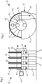
- a device 10 for filtering a suspension is in connection with the Figures 1 to 4 explained.
- a total of four disc filters 20 are arranged on a common filter shaft 30, which is driven in rotation by a drive 31.
- the disk filters 20 are each immersed in a semi-circular trough 12 which is filled with a suspension to be filtered via a supply line 32 .
- Each disk filter 20 is divided into a large number of chamber-like filter segments 22 which are provided with a filter medium 26, for example a filter cloth or a filter membrane, at least on their side surfaces. Due to an existing pressure difference, the suspension is sucked into the trough 12 , with liquid from the suspension penetrating the filter medium 26 as so-called filtrate and entering an inner filtrate space 24 of the respective filter segment 22 . At the same time, solid particles from the suspension settle on the outside of the filter medium 26 as a so-called filter cake.
- a filter medium 26 for example a filter cloth or a filter membrane
- the filter shaft 30 is driven clockwise, with the respective disc filter 20 on exits the filter trough 12 at a 9 o'clock position.
- the inner filtrate space 24 of the respective filter segment 22 compared to the ambient atmosphere, which can also be a pressure space, so that basically residual liquid in the filtered filter cake is sucked into the filtrate space 24 and filtrate into the respective filtrate space 24 is passed from the filter segment 22 into a filtrate discharge line 34 on the filter shaft 30 .
- the filtrate discharge line 34 can be designed as a collecting pipe to which a large number of filter segments 22 of the parallel disk filters 20 and in particular all filter segments 22 are connected in the same angular position via a respective passage opening 36 in a line-connected manner.
- Several filtrate discharge lines 34 for filter segments 22 can be provided in the different angular positions in the filter shaft 30 .
- the filtrate can thus be discharged from the individual filter segments 22 via the respective filtrate discharge line 34 to a basically known control head 50 .
- the control head 50 basically has a rotor rotating with the filter shaft 30 and a stationary stator. In the exemplary embodiment shown, the control head 50 has two outlets 52 for the filtrate on the stator of the control head 50 .
- a removal device for removing the filter cake from the disc filters 20 with a removal 18 can be provided between a 1 o'clock position and a 3 o'clock position. After the cake has been removed, the respective filter segment 22 can be immersed again in the suspension in the trough 12 for a further filtration step.
- the filtrate drain is in figure 5 represented by two black arrows.
- a stator of the control head 50 is shown schematically, individual zones being provided for feeds and discharges.
- a supply opening for the expulsion gas from the gas supply device 40 for entry into the filter segment 22 located in this angular position is provided approximately at the 9 o'clock position. In a 2 o'clock position there can be a supply for an exhaust gas for blowing off the filter cake. Areas in between can have openings for filtrate removal, which is indicated by black arrows.
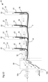
- FIG. 7 and 8 an embodiment of a device 10 according to the invention is shown, in which a total of five disc filters 20 are arranged on a filter shaft 30 with a filtrate discharge line 34 .
- a total of five disc filters 20 are arranged on a filter shaft 30 with a filtrate discharge line 34 .
- only individual filter segments 22 are shown from the disc filters 20, in which an emptying according to the principle set out above according to figures 5 and 6 he follows.
- the filtrate 5 is discharged and the expulsion gas is supplied via the same collecting pipe of the respective filtrate discharge line 34.
- a single control head 50 is provided on only one side of the filter shaft 30, via which the expulsion gas is supplied and the filtrate 5 is discharged.
- FIG 9 Another possible embodiment variant of the invention is shown, wherein expulsion gas is fed continuously via the filtrate discharge line 34 into the filtrate space 24 of a filter segment 22 in the emptying zone. Simultaneously, with the supply of the expulsion gas, a continuous removal and expulsion of the filtrate 5 from the filtrate chamber 24 into the filtrate discharge line 34 is effected, as illustrated in FIG figure 9 is shown.
- a dividing wall 38 made of sheet metal, for example, can be drawn into the filtrate discharge line 34 and has sections 39 that extend into the area of the passage opening 36 at the foot of the filter segments 22 .
- the partition wall 38 is shown in Fig figure 10 also shown separate from the filtrate line 34 .
- the partition wall 38 allows two separate areas to be created within the filtrate discharge line 34, with an area for conducting the filtrate 5 and an area separate therefrom being formed as part of the gas supply device 40 for supplying the expulsion gas into the filtrate space 24 of the filter segment 22.
- a calming zone can be formed in the collecting tube, in which the expulsion gas can be conducted into the filtrate chambers 24 in the opposite direction to the filtrate flow.
- the sections 39 of the partition wall 38 can also be made longer and extend into the filtrate chambers 24 of the filter segments 22 .
- a kind of chimney effect can be produced, with the lighter phase, namely the expulsion gas, being able to rise particularly well.
- FIG 11 Another possible embodiment of a device 10 according to the invention for filtration is in figure 11 shown schematically, with a control head 50 with a stator 54 and a rotor 56, both the expulsion gas is supplied via a first connection 52a and the filtrate 5 can be discharged via a second connection 52b together with the outflowing gas.
- Expulsion gas is routed via the first connection 52a to a supply line 42 as part of the gas supply device 40 to the opposite end of the collecting tube of the filtrate outlet line 34 and introduced into the filtrate line 34 .
- the expulsion gas can rise through the passages 36 in the respective filtrate spaces 24 and thereby Expel remaining filtrate 5 in the filtrate chambers 24 of the disk filter 20 downwards into the filtrate line 34 . From there, the filtrate 5 is conducted with the expanded expulsion gas to the second outlet 52b on the stator 54 of the control head 50.
- FIG 12 a part of the control head 50 provided for this purpose with the stator 54 is shown in more detail.
- a slot is provided in an inner area for supplying the expulsion gas to the stator 54 when it is transferred to the rotor 56, which slot is connected to the gas supply device 40 with a control valve 44 for supplying the expulsion gas.
- Filtrate can be discharged via further openings on the stator 54 of the control head 50, which is indicated by black arrows.
- a discharge gas for throwing off the filter cake can be conducted into the filtrate chamber 24 via a further opening approximately at the 2 o'clock position.
- FIG 13 is a to figure 11 similar device 10 with a one-sided control head 50, with an expulsion gas being introduced via a first connection 52a through a hose-like supply line 42 as part of the gas supply device 40 within the filtrate discharge line 34 via individual hoses 43 into the respective filtrate space 24 of a filter segment 22 of a disc filter 20.
- the individual hose 43 can extend far into the interior of the filtrate space 24 in order to bring about a reliable expulsion of filtrate 5 from above to the respective passage opening 36 in the filter segment 22 .
- the filtrate 5 with expanded expulsion gas is then discharged via the control head 50 via a second outlet 52b.
- the hose can also be routed outside of the filter discharge line 34 and can be implemented by sealed individual passages from the outside into the through-openings 36 or filter segments 22 (eg with plug-in connections).
- FIG figure 14 Another possible embodiment variant of a device 10 according to the invention for filtration is shown schematically in FIG figure 14 shown, with a gas supply device 40 having a control valve 44 being arranged on the outer circumference of each filter segment 22 .
- gas under pressure can be introduced from the outside into the filtrate space 24 .
- filtrate 5 located in the filtrate space 24 can be efficiently discharged downwards to the respective filtrate pipe.
Landscapes
- Chemical & Material Sciences (AREA)
- Chemical Kinetics & Catalysis (AREA)
- Filtration Of Liquid (AREA)
Priority Applications (1)
| Application Number | Priority Date | Filing Date | Title |
|---|---|---|---|
| EP21208017.0A EP4180108A1 (fr) | 2021-11-12 | 2021-11-12 | Procédé et dispositif de filtrage d'une suspension |
Applications Claiming Priority (1)
| Application Number | Priority Date | Filing Date | Title |
|---|---|---|---|
| EP21208017.0A EP4180108A1 (fr) | 2021-11-12 | 2021-11-12 | Procédé et dispositif de filtrage d'une suspension |
Publications (1)
| Publication Number | Publication Date |
|---|---|
| EP4180108A1 true EP4180108A1 (fr) | 2023-05-17 |
Family
ID=78617317
Family Applications (1)
| Application Number | Title | Priority Date | Filing Date |
|---|---|---|---|
| EP21208017.0A Pending EP4180108A1 (fr) | 2021-11-12 | 2021-11-12 | Procédé et dispositif de filtrage d'une suspension |
Country Status (1)
| Country | Link |
|---|---|
| EP (1) | EP4180108A1 (fr) |
Cited By (1)
| Publication number | Priority date | Publication date | Assignee | Title |
|---|---|---|---|---|
| CN118122020A (zh) * | 2024-05-10 | 2024-06-04 | 赣州新磁稀土产业有限公司 | 一种稀土加工用稀土磁性过滤处理装置 |
Citations (4)
| Publication number | Priority date | Publication date | Assignee | Title |
|---|---|---|---|---|
| DE340183C (de) * | 1918-12-22 | 1921-09-03 | Hans Jung | Verfahren und Vorrichtung zum ununterbrochenen Filtrieren und verschiedenartigen Behandeln des Filtergutes ohne Zellenteilung des Pressraumes und Waschung der Filterflaechen im Gegenstrom |
| DE2804779A1 (de) | 1978-02-04 | 1979-08-09 | Krauss Maffei Ag | Mehrscheiben-drehfilter |
| DE3616201A1 (de) * | 1986-05-14 | 1987-11-19 | Kloeckner Humboldt Deutz Ag | Drehfilter |
| WO2020185484A1 (fr) * | 2019-03-08 | 2020-09-17 | Benesi Steve C | Appareil de filtre, secteurs de disque de filtre, éléments de filtre et utilisations |
-
2021
- 2021-11-12 EP EP21208017.0A patent/EP4180108A1/fr active Pending
Patent Citations (4)
| Publication number | Priority date | Publication date | Assignee | Title |
|---|---|---|---|---|
| DE340183C (de) * | 1918-12-22 | 1921-09-03 | Hans Jung | Verfahren und Vorrichtung zum ununterbrochenen Filtrieren und verschiedenartigen Behandeln des Filtergutes ohne Zellenteilung des Pressraumes und Waschung der Filterflaechen im Gegenstrom |
| DE2804779A1 (de) | 1978-02-04 | 1979-08-09 | Krauss Maffei Ag | Mehrscheiben-drehfilter |
| DE3616201A1 (de) * | 1986-05-14 | 1987-11-19 | Kloeckner Humboldt Deutz Ag | Drehfilter |
| WO2020185484A1 (fr) * | 2019-03-08 | 2020-09-17 | Benesi Steve C | Appareil de filtre, secteurs de disque de filtre, éléments de filtre et utilisations |
Cited By (1)
| Publication number | Priority date | Publication date | Assignee | Title |
|---|---|---|---|---|
| CN118122020A (zh) * | 2024-05-10 | 2024-06-04 | 赣州新磁稀土产业有限公司 | 一种稀土加工用稀土磁性过滤处理装置 |
Similar Documents
| Publication | Publication Date | Title |
|---|---|---|
| EP0654294B1 (fr) | Procédé et dispositif de filtration de particules solides de liquides et le rinçage du filtre à contre-courant | |
| EP1583597B9 (fr) | Dispositif de filtrage | |
| EP0572369A2 (fr) | Dispositif de filtration à nettoyage par contre-courant pour la filtration des liquides ayant haute viscosité | |
| EP1592489A2 (fr) | Dispositif de filtration et procede de filtration | |
| CH668195A5 (de) | Filterpresse fuer die anschwemmfiltration. | |
| EP0086770B1 (fr) | Dispositif de filtration, spéciallement adapté pour la fitration de boissons | |
| DE10340366B4 (de) | Filtervorrichtung | |
| EP4180108A1 (fr) | Procédé et dispositif de filtrage d'une suspension | |
| DE3107639C2 (fr) | ||
| EP0540546B1 (fr) | Dispositif de filtration pour matiere thermoplastique | |
| DE102010019873B4 (de) | Filtrationsvorrichtung | |
| EP2896444A1 (fr) | Dispositif et procédé destinés à filtrer un liquide à l'aide d'un dispositif de nettoyage sans interruption de processus | |
| EP0178389A2 (fr) | Filtre-presse à chambres | |
| DE1611068A1 (de) | Rueckspuelfilter | |
| AT391818B (de) | Filtervorrichtung | |
| CH705773A2 (de) | Schubzentrifuge und Verfahren zum Betreiben einer Schubzentrifuge. | |
| DE3622103A1 (de) | Scheiben - membran - pressfilter | |
| DE1536826C3 (de) | Filtervorrichtung | |
| DE102022127838A1 (de) | Klärschlammfilter mit mechanischer Abreinigung und einem integrierten mechanischen Austragsystem | |
| DE1875987U (de) | Dekantier- und/oder siebzentrifuge. | |
| DE3430992C2 (de) | Filtervorrichtung | |
| EP3098215B1 (fr) | Dispositif et procede de traitement d'acide terephtalique | |
| DE3617054C2 (de) | Eindicker | |
| AT508753B1 (de) | Drehfilter | |
| DE29518534U1 (de) | Filter zum kontinuierlichen Filtern von Feststoffe aufweisenden Flüssigkeiten |
Legal Events
| Date | Code | Title | Description |
|---|---|---|---|
| PUAI | Public reference made under article 153(3) epc to a published international application that has entered the european phase |
Free format text: ORIGINAL CODE: 0009012 |
|
| STAA | Information on the status of an ep patent application or granted ep patent |
Free format text: STATUS: THE APPLICATION HAS BEEN PUBLISHED |
|
| AK | Designated contracting states |
Kind code of ref document: A1 Designated state(s): AL AT BE BG CH CY CZ DE DK EE ES FI FR GB GR HR HU IE IS IT LI LT LU LV MC MK MT NL NO PL PT RO RS SE SI SK SM TR |
|
| STAA | Information on the status of an ep patent application or granted ep patent |
Free format text: STATUS: REQUEST FOR EXAMINATION WAS MADE |
|
| 17P | Request for examination filed |
Effective date: 20231030 |
|
| RBV | Designated contracting states (corrected) |
Designated state(s): AL AT BE BG CH CY CZ DE DK EE ES FI FR GB GR HR HU IE IS IT LI LT LU LV MC MK MT NL NO PL PT RO RS SE SI SK SM TR |
|
| STAA | Information on the status of an ep patent application or granted ep patent |
Free format text: STATUS: EXAMINATION IS IN PROGRESS |
|
| 17Q | First examination report despatched |
Effective date: 20240722 |