EP4180000B1 - Medizinische armvorrichtung - Google Patents
Medizinische armvorrichtung Download PDFInfo
- Publication number
- EP4180000B1 EP4180000B1 EP21837986.5A EP21837986A EP4180000B1 EP 4180000 B1 EP4180000 B1 EP 4180000B1 EP 21837986 A EP21837986 A EP 21837986A EP 4180000 B1 EP4180000 B1 EP 4180000B1
- Authority
- EP
- European Patent Office
- Prior art keywords
- axis
- pulley
- rerouting
- motor
- rotation
- Prior art date
- Legal status (The legal status is an assumption and is not a legal conclusion. Google has not performed a legal analysis and makes no representation as to the accuracy of the status listed.)
- Active
Links
Images












Classifications
-
- A—HUMAN NECESSITIES
- A61—MEDICAL OR VETERINARY SCIENCE; HYGIENE
- A61B—DIAGNOSIS; SURGERY; IDENTIFICATION
- A61B34/00—Computer-aided surgery; Manipulators or robots specially adapted for use in surgery
- A61B34/30—Surgical robots
-
- A—HUMAN NECESSITIES
- A61—MEDICAL OR VETERINARY SCIENCE; HYGIENE
- A61B—DIAGNOSIS; SURGERY; IDENTIFICATION
- A61B90/00—Instruments, implements or accessories specially adapted for surgery or diagnosis and not covered by any of the groups A61B1/00 - A61B50/00, e.g. for luxation treatment or for protecting wound edges
- A61B90/50—Supports for surgical instruments, e.g. articulated arms
-
- A—HUMAN NECESSITIES
- A61—MEDICAL OR VETERINARY SCIENCE; HYGIENE
- A61B—DIAGNOSIS; SURGERY; IDENTIFICATION
- A61B34/00—Computer-aided surgery; Manipulators or robots specially adapted for use in surgery
- A61B34/30—Surgical robots
- A61B34/37—Leader-follower robots
-
- A—HUMAN NECESSITIES
- A61—MEDICAL OR VETERINARY SCIENCE; HYGIENE
- A61B—DIAGNOSIS; SURGERY; IDENTIFICATION
- A61B34/00—Computer-aided surgery; Manipulators or robots specially adapted for use in surgery
- A61B34/70—Manipulators specially adapted for use in surgery
-
- A—HUMAN NECESSITIES
- A61—MEDICAL OR VETERINARY SCIENCE; HYGIENE
- A61B—DIAGNOSIS; SURGERY; IDENTIFICATION
- A61B34/00—Computer-aided surgery; Manipulators or robots specially adapted for use in surgery
- A61B34/70—Manipulators specially adapted for use in surgery
- A61B34/71—Manipulators operated by drive cable mechanisms
-
- A—HUMAN NECESSITIES
- A61—MEDICAL OR VETERINARY SCIENCE; HYGIENE
- A61B—DIAGNOSIS; SURGERY; IDENTIFICATION
- A61B34/00—Computer-aided surgery; Manipulators or robots specially adapted for use in surgery
- A61B34/30—Surgical robots
- A61B2034/305—Details of wrist mechanisms at distal ends of robotic arms
Definitions
- the present disclosure relates to a medical arm device used, for example, for supporting a medical instrument.
- An object of the present disclosure is to provide a medical arm device that is compact and includes a tip part in which a multi-degree-of-freedom active joint is condensed with a high torque so as to be able to hold a medical instrument such as an endoscope.
- Fig. 1 illustrates an appearance configuration example of a medical arm device 100 applied to laparoscopic surgery.
- the illustrated medical arm device 100 has a structure in which an arm having a multi-link structure supports an endoscope at a tip part, and orthogonal rotation axes of three degrees of freedom for determining an attitude of the endoscope are intensively disposed.
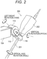
- Fig. 2 illustrates an enlarged structure of the tip part of the medical arm device 100 that supports the endoscope 200.
- the endoscope 200 includes a lens barrel 201 inserted into a body cavity of a patient at a tip, and a camera head 202 connected to a proximal end of the lens barrel 201.
- the lens barrel 201 may be either a rigid mirror including a rigid lens barrel or a flexible mirror including a flexible lens barrel.
- An optical system and an imaging element are disposed in the camera head 202. Reflected light (observation light) from an observation target such as a surgical site is imaged on the imaging element by the optical system.
- the tip part of the medical arm device 100 may support a medical instrument other than the endoscope 200.
- a structure in which the roll axis wire 503 is wound around the roll axis pulley 1101 will be specifically described.
- the two-groove pulley 1102 that is rotatable around a rotation axis parallel to the pitch axis 114 on the root side of the pitch axis 114 and accommodates rotation around the pitch axis 114
- the two-groove pulley 1103 that is rotatable around the pitch axis 114 and changes the path along the pitch axis 114
- two rerouting pulleys 1104 and 1105 that change the path of the roll axis wire 503 between the pitch axis and the yaw axis
- a two-groove pulley 1106 coaxial with the yaw axis 115 that changes the path along the yaw axis 115
- two rerouting pulleys 1107 and 1108 that change the path of the roll axis wire 503 between the
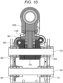
- the two-groove pulley 1102 is rotatably supported around a rotation axis parallel to the pitch axis 114 by the shaft 704 on the root side of the pitch axis 114, and the two-groove pulley 1103 is rotatably supported around the pitch axis 114 by the shaft 703 coaxial with the pitch axis 114 (See the above and Fig. 10 .).
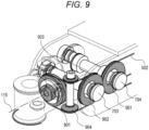
- the rerouting pulleys 1104 and 1105 are respectively supported on side surfaces on an opposite side of the pitch axis component 701 (not illustrated in Figs. 8 and 9 ) so as to be rotatable on the identical axis around an axis orthogonal to the pitch axis 114 and the yaw axis 115.
- the two-groove pulley 1106 is supported on a tip surface of the pitch axis component 701 via a bearing so as to be rotatable around the yaw axis 115 (See Fig. 10 .).
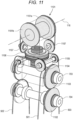
- the rerouting pulley 1107 is supported on a side surface of the second connection part 1002 (not illustrated in Figs. 11 and 12 ) so as to be rotatable around an axis parallel to the roll axis 116.
- the reroute 1108 is supported on a side surface of the second connection part 1002 (not illustrated in Figs. 11 and 12 ) so as to be rotatable around an axis orthogonal to the roll axis 116.
- the roll axis wire 503 comes out of the output axis pulley 613 (not illustrated in Figs. 11 and 12 ) of the roll axis motor 603, the roll axis wire is wound around the rerouting pulley to change the route along the pitch axis by winding the two-groove pulley 1102 on the root side and the two-groove pulley 1103 coaxial with the pitch axis 114 in this order from the longitudinal direction (or the pitch axis direction) of the fourth link 104, then wound around the rerouting pulley 1104 to change the path from the pitch axis direction to the yaw axis direction, then wound around the two-groove pulley 1106 to change the path along the yaw axis, further wound around the rerouting pulley 1107 to change the path from the yaw axis direction to the roll axis direction, and wound around one pulley 1101a of the roll axis pull
- the roll axis pulley 1101 includes a set of pulleys 1101a and 1101b, but may be a two-groove pulley similarly to the yaw axis.
- the rotation movable range around the roll axis 116 is ⁇ 170 deg.
- a diameter of the set of pulleys 1101a and 1101b of the roll axis pulley 1101 needs to be the same. It is preferable that these diameters are larger because a larger transmission torque can be handled.
- the path is changed from the yaw axis direction to the pitch axis direction by the rerouting pulley 1104 while being wound around a groove inside the two-groove pulley 1103, and on the backward path side of the roll axis wire 503, the path is changed from the pitch axis direction to the yaw direction by the rerouting pulley 1105, and then the roll axis wire is wound around the outside of the two-groove pulley 1104.
- the diameter of each groove of the two-groove pulley 1103 coaxial with the pitch axis 114 is the same, and it is further preferable that the diameter is the same as that of the yaw axis pulley 801 in terms of design.
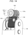
- the rerouting pulley 1107 is disposed to move from the side surface of the second connection part 1002 facing the roll axis 116 to the side surface of the second connection part 1002 facing a direction orthogonal to the roll axis 116.
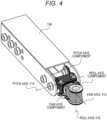
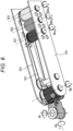
- Fig. 6 illustrates an example in which the pitch axis motor 601, the yaw axis motor 602, and the roll axis motor 603 are disposed in this order from the tip side, but the order of disposing these motors may be changed. However, it is preferable to dispose the heavy motors in this order from the root side (or the proximal end side) because the output required for driving the three degrees of freedom of the tip part can be reduced.
- the roll axis 116 is used for the optical axis rotation of the endoscope 200 (See Fig. 2 .), a small torque is sufficient, and there is no problem in design even if the group of pulleys for driving around the roll axis 116 is disposed on the outermost side.
- the two-groove pulley 901 is used on a front side (proximal end side) of the pitch axis 114 in order to make the yaw axis wire 502 accommodate the rotation around the pitch axis 114.
- the two-groove pulley 1102 is used on the front side (proximal end side) of the pitch axis 114 in order to make the roll axis wire 503 accommodate the rotation around the pitch axis 114.
- Both of these two two-groove pulleys 901 and 1102 are supported by the shaft 704 parallel to the pitch axis 114.
- the two-groove pulleys 901 and 1102 accommodating the pitch axis rotation are preferably close to the two-groove pulleys 902 and 1103 coaxial with the pitch axis, respectively, but may be slightly separated from each other.
- the two-groove pulleys 901 and 1102 accommodating the pitch axis rotation are disposed close to the two-groove pulleys 902 and 1103 coaxial with the pitch axis, respectively.
- These two-groove pulleys 901 and 1102 for accommodating the pitch axis rotation may not be of the same diameter.
- the two-groove pulleys 901 and 1102 for accommodating the pitch axis rotation are both rotatably supported by the shaft 702 that is coaxial with the pitch axis 114, but may also be supported by shafts that are different from each other. Furthermore, the shaft supporting the two-groove pulley 901 and the shaft supporting the two-groove pulley 1102 may not have the identical axis. In a case where the shaft supporting the two-groove pulley 901 and the shaft supporting the two-groove pulley 1102 are separated, there is an advantage that the layout of the wiring to the tip is easily designed.
- the two-groove pulley 902 is used to change the path of the yaw axis wire 502 along the pitch axis 114.
- the two-groove pulley 1103 is used to change the path of the roll axis wire 503 along the pitch axis 114. Both of these two two-groove pulleys 902 and 1103 are supported by the shaft 703 coaxial with the pitch axis 114.
- These two-groove pulleys 902 and 1103 for accommodating the pitch axis rotation may not be of the same diameter. Furthermore, none of these two-groove pulleys 902 and 1103 for accommodating the pitch axis rotation may have the same diameter as the pulley 702 for driving the pitch axis.
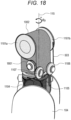
- the forward path and the backward path of the roll axis wire 503 are respectively wound around the set of pulleys 1101a and 1101b rotatably attached around the roll axis 116 at both ends of the structure body 1101 including a hollow cylinder.
- a two-groove pulley may be attached to one side of the hollow cylindrical structure body 1101, and the forward path and the backward path of the roll axis wire 503 may be wound around each groove of the two-groove pulley.
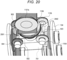
- Fig. 20 illustrates an enlarged structure for realizing the rotational degree of freedom around the yaw axis 115 in the tip part of the medical arm device 100.
- the yaw axis pulley 801 is supported on a tip surface of the pitch axis component 701 so as to be rotatable coaxially with the yaw axis 115.
- the two-groove pulley 1106 and the yaw axis pulley 801 are supported on the tip surface of the pitch axis component 701 so as to be rotatable coaxially with the yaw axis 115.
- a pair of the rerouting pulleys 903 and 904 for rerouting the pitch axis wire 501 between the yaw axis and the pitch axis is supported on the side surface of the pitch axis component 701.
- the two rerouting pulleys 903 and 904 having different diameters are disposed on the identical axis in order to smoothly reroute the yaw axis wire 502 and wind the yaw axis wire around the yaw axis pulley 801 compatible with the two-groove pulley 902 rotating around the pitch axis 114.
- the two rerouting pulleys 903 and 904 are rotatably supported by a shaft 2001 constituting the identical axis.
- a pair of the rerouting pulleys 1104 and 1105 for rerouting the roll axis wire 503 between the yaw axis and the pitch axis are supported on side surfaces on an opposite side of the pitch axis component 701.
- the two rerouting pulleys 1104 and 1105 having different diameters are disposed on the identical axis in order to smoothly reroute the roll axis wire 503 and wind the wire around the two-groove pulley 1106 which is compatible with the two-groove pulley 1103 rotating around the pitch axis 114.
- the two rerouting pulleys 1104 and 1105 are rotatably supported by a shaft 2002 constituting the identical axis.
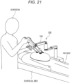
- Fig. 21 illustrates an example of how the medical arm device 100 illustrated in Fig. 1 corresponds to a surgical procedure.
- the medical arm device 100 is installed on an opposite side of the surgeon across a surgical bed. Then, the surgeon performs laparoscopic surgery on a patient on the surgical bed while observing the state of a surgical site in an abdominal cavity observed using an endoscope (not illustrated) held at the tip of the medical arm device 100.
- the tip part can realize a small and lightweight structure by intensively disposing orthogonal rotation axes of three degrees of freedom that determine the attitude of the endoscope, and can avoid interference with the surgeon's hand or arm.
- the tip part with three degrees of freedom not only the tip part with three degrees of freedom but also the fourth link 104 supporting the tip part is in an interference region with the surgeon's hand or arm. Therefore, it can be said that it is desirable to design the fourth link 104 with a reduced diameter in order to avoid collision with the surgeon's hand or arm.
- a wire transmission mechanism is used to transmit the rotation of each of the motors 2401 to 2403 to the tip part side, the wire transmission mechanism is not illustrated in Figs. 24 and 25 for simplification of the drawings.
- the wire transmission mechanism it is possible to transmit the rotation of each of the motors 2401 to 2403 with high accuracy by suppressing the occurrence of backlash with high efficiency of the driving force of the actuator. Since the load torque of each rotation mechanism of three degrees of freedom of the tip part is relatively small, it is possible to cover low strength which is a disadvantage of the wire transmission mechanism.
- each of the motors 2401 to 2403 is disposed on the root side of the fourth link 104 while being separated from the actual joint position of the tip part, the tip part is reduced in weight, and the torque required for the rotational drive of the fourth link 104 can be reduced, which contributes to downsizing of the entire medical arm device 100.
- a difference between the arrangement example of the actuators illustrated in Figs. 28 and 29 and the arrangement example of the actuators illustrated in Fig. 6 is that a part of a section on the tip part side where the three motors 2801 to 2803 are not disposed in the fourth link 104 is reduced in diameter.
- the motor 3004 for rotating the fourth link 104 around the pitch axis cannot be disposed in the third joint part 113. Therefore, in the arrangement example of the actuators illustrated in Figs. 30 and 31 , the motor 3004 for driving the third joint part 113 is disposed outside the third joint part 113 (on an opposite side of the fourth link 104). Then, a rotational force of the motor 3004 is transmitted to the third joint part 113 accommodating the third motor 3003 using a steel belt 3005 to realize the rotation of the fourth link 104 around the pitch axis.
- the third joint part 113 has a hollow cylindrical structure having a central axis in the pitch axis direction, and is joined and integrated with an inner wall of the fourth link 104.
- the third motor 3003 and the motor 3004 are fixed to a frame of the third link 103.
- the third motor 3003 is disposed in the hollow cylinder of the third joint part 113 such that the rotation axis coincides with a joint axis of the third joint part 113, and is rotatably supported around the joint axis via a bearing.
- Figs. 32 and 33 illustrate an example in which all three motors 3201 to 3203 that drive the respective rotation mechanisms of the tip part having the three rotation mechanisms are disposed on the fourth link 104 with the output axis direction aligned with the longitudinal direction of the fourth link 104, and a motor 3204 for driving the third joint part 113 is disposed outside the third joint part 113 (on an opposite side of the fourth link 104).
- Fig. 32 illustrates a state viewed from a direction of a side surface of the motor 3204
- Fig. 33 illustrates a state viewed from a direction of a rotation axis of the motor 3204.
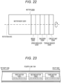
- all of the three motors 3201 to 3203 are cylindrical electromagnetic actuators elongated in the output axis direction as illustrated in Fig. 22 .
- the arrangement example of the actuators illustrated in Figs. 32 and 33 is common to the arrangement example of the actuators illustrated in Figs. 30 and 31 in that the motor 3204 for driving the third joint part 113 is disposed outside the third joint part 113 (on an opposite side of the fourth link 104).
- the arrangement example of the actuators illustrated in Figs. 32 and 33 is different from the example illustrated in Figs. 30 and 31 in that the first to third motors 3201 to 3201 are disposed in the fourth link 104 and none of the actuators is disposed in the third joint part 113.
- the entire fourth link 104 can be reduced in diameter by disposing all the motors 3201 to 3203 on the fourth link 104 with the output axis direction aligned with the longitudinal direction of the fourth link 104. Furthermore, by not disposing any motor in the third joint part 113, the third joint part 113 is downsized, so that a small diameter part of the fourth link 104 can be secured in a long section.
- the third joint part 113 is a rotation mechanism that rotates the fourth link 104 around the vertical rotation axis (alternatively, the pitch axis) on the root side (described above).
- the third joint part 113 has a hollow cylindrical structure having a central axis in the pitch axis direction, and is joined and integrated with an inner wall of the fourth link 104.
- the third joint part 113 is supported by the third link 103 via a bearing disposed in the hollow cylinder so as to be rotatable around the joint axis.
- An output axis pulley 3206 of the motor 3204 includes a hollow cylinder that covers an outer periphery of the motor 3204. Then, a steel belt 3205 is wound around the third joint part 113 and the output axis pulley 3206. Therefore, the rotation of the motor 3204 is transmitted to the third joint axis 113 via the steel belt 3205, and the fourth link 104 can be rotated around the joint axis of the third joint part 113 (around the pitch axis or around the vertical rotation axis). Furthermore, by using the steel belt 3205 including a metal plate such as stainless steel for the transmission mechanism of the rotation of the motor 3204, it is possible to perform drive transmission with high strength, wide movable range, high efficiency, and high accuracy without rattling.
- a transmission mechanism for transmitting a rotational force of each of the motors to the tip part is required.
- a driving force of the actuator is transmitted with high efficiency and with high accuracy while suppressing the occurrence of backlash. Since the load torque of each rotation mechanism of three degrees of freedom of the tip part is relatively small, it is possible to cover low strength which is a disadvantage of the wire transmission mechanism. Furthermore, it is possible to maximally utilize small and lightweight drive transmission which is an advantage of the wire transmission mechanism.
- a rotational force of the motor is extracted using a wire wound around the output axis pulley attached to an output axis of the motor. Then, the position and direction of the pitch axis or the roll axis of the wire are changed appropriately using the rerouting pulley to avoid interference with other motors and other components existing between the output axis pulley and the tip part, and the motor and the target component are connected by the wire.
- Figs. 34 and 35 illustrate a configuration example of a wire transmission mechanism in a case where all three motors 3401 to 3403 described in section O-1 described above are disposed with the output axis direction aligned with the longitudinal direction of the fourth link 104. However, in Figs. 34 and 35 , a rotational position of the fourth link 104 around the longitudinal axis is changed by 90 degrees.
- a position of a wire 3410 wound around an output axis pulley 3411 of the first motor 3401 in the fourth link 104 is adjusted via a rerouting pulley 3412 on a forward path side and a rerouting pulley 3413 on a backward path side, and is directed toward the tip part side. Furthermore, a position of a wire 3420 wound around an output axis pulley 3421 of the second motor 3402 in the fourth link 104 is adjusted via a rerouting pulley 3422 on a forward path side and a rerouting pulley 3423 on a backward path side.
- the wire 3420 is disposed so as not to interfere with the wire 3410 by changing the rotational position of the rerouting pulleys 3422 and 3423 around the longitudinal axis only by 180 degrees with respect to the rerouting pulleys 3412 and 3413. Furthermore, a position of a wire 3430 wound around an output axis pulley 3431 of the third motor 3403 in the fourth link 104 is adjusted via a rerouting pulley 3432 on a forward path side and a rerouting pulley 3433 on a backward path side.
- the rerouting pulleys 3432 and 3433 are disposed at the same rotational position around the longitudinal axis as the rerouting pulleys 3412 and 3413, and at different positions in a radial direction (or width direction) the wire 3430 is disposed so as not to interfere with the wire 3410.
- Figs. 36 and 37 illustrate a configuration example of a wire transmission mechanism in a case where, out of three motors 3601 to 3603 described in section O -2 described above, the first motor 3601 and the second motor 3602 are disposed with the output axis direction aligned with the longitudinal direction of the fourth link 04, and the third motor 3603 on the root side is disposed with the output axis direction oriented in a direction orthogonal to the longitudinal direction of the fourth link 104.
- a rotational position of the fourth link 104 around the longitudinal axis is changed by 90 degrees.
- a position of a wire 3610 wound around an output axis pulley 3611 of the first motor 3601 in the fourth link 104 is adjusted via a rerouting pulley 3612 on a forward path side and a rerouting pulley 3613 on a backward path side, and is directed toward the tip part side. Furthermore, a position of a wire 3620 wound around an output axis pulley 3621 of the second motor 3602 in the fourth link 104 is adjusted via a rerouting pulley 3622 on a forward path side and a rerouting pulley 3623 on a backward path side. Similarly to the example illustrated in Figs.
- a position of a wire 3810 wound around an output axis pulley 3811 of the first motor 3801 in the fourth link 104 is adjusted via a rerouting pulley 3812 on a forward path side and a rerouting pulley 3813 on a backward path side, and is directed toward the tip part side. Furthermore, an output axis of the second motor 3802 is orthogonal to the longitudinal direction of the fourth link 104, and an output axis pulley 3821 of the second motor 3802 is disposed in a direction opposite to the wire 3810.
- a wire 3820 wound around the output axis pulley 3821 can be wired in the fourth link 104 so as to avoid interference with the first motor 3801, the wire 3810, and the like disposed on the tip side.
- a pulley (not illustrated) for changing the path or adjusting the position may be further disposed on at least one of a forward path side or a backward path side of the wire 3820.
- an output axis of the third motor 3803 is orthogonal to the longitudinal direction of the fourth link 104, and an output axis pulley 3831 of the third motor 3803 is disposed in the same direction as the output axis pulley 3821 of the second motor 3802.
- a position of the output axis pulley 3831 is shifted in a direction orthogonal to the longitudinal direction of the fourth link 104 so as not to overlap with the output axis pulley 3821. Therefore, the wire 3830 wound around the output axis pulley 3831 can be wired in the fourth link 104 so as to avoid interference with the first motor 3801 disposed on the tip side, the second motor 3802, each of the wires 3810 and 3820, and the like.
- a pulley (not illustrated) for changing the path or adjusting the position may be further disposed on at least one of a forward path side or a backward path side of the wire 3830.
- the embodiments in which the present disclosure is applied to a medical arm device that supports an endoscope have been mainly described, but the gist of the present disclosure is not limited thereto.
- the present disclosure can be similarly applied to a medical arm device that supports a medical instrument other than the endoscope, for example, forceps, a pneumoperitoneum tube, an energy treatment tool, tweezers, a retractor, or the like at the tip, and the attitude of the medical instrument to be supported can be determined without backlash in three orthogonal degrees of freedom.
Landscapes
- Health & Medical Sciences (AREA)
- Surgery (AREA)
- Life Sciences & Earth Sciences (AREA)
- Engineering & Computer Science (AREA)
- Medical Informatics (AREA)
- General Health & Medical Sciences (AREA)
- Biomedical Technology (AREA)
- Heart & Thoracic Surgery (AREA)
- Nuclear Medicine, Radiotherapy & Molecular Imaging (AREA)
- Molecular Biology (AREA)
- Animal Behavior & Ethology (AREA)
- Veterinary Medicine (AREA)
- Public Health (AREA)
- Robotics (AREA)
- Oral & Maxillofacial Surgery (AREA)
- Pathology (AREA)
- Manipulator (AREA)
- Endoscopes (AREA)
Claims (11)
- Medizinische Armvorrichtung (100), umfassend:einen ersten Armteil, der einen Spitzenteil einschließt, der ein medizinisches Instrument (200) hält, und eine Verbindung (104), die den Spitzenteil stützt; undeinen zweiten Armteil, der den ersten Armteil stützt, wobeider Spitzenteil Folgendes einschließteine Struktur, bei der drei Drehachsen in der Reihenfolge einer Drehachse (116) um eine Längsachse des medizinischen Instruments (200), einer Gierachse (115), die das medizinische Instrument (200) in Bezug auf eine Spitze der Verbindung (104) nach links und rechts dreht, und einer Nickachse (114), die das medizinische Instrument (200) in Bezug auf die Spitze der Verbindung (104) in der Reihenfolge von einem äußersten Spitzenteil nach oben und unten dreht, angeordnet sind, undwobei an der Verbindung (104) ein erster Draht (502) zur Drehübertragung der Gierachse (115), ein zweiter Draht (503) zur Drehübertragung der Rollachse (116), eine erste Umlenkrolle, die den ersten Draht (502) zwischen der Nickachse (114) und der Gierachse (115) umleitet, eine zweite Umlenkrolle, die den zweiten Draht (503) zwischen der Nickachse (114) und der Gierachse (115) umleitet, und eine dritte Umlenkrolle, die den zweiten Draht (503) zwischen der Gierachse (115) und der Rollachse (116) umleitet, angeordnet sind;wobei mindestens eine der ersten Umlenkrolle oder der zweiten Umlenkrolle einen Satz von Umlenkrollen mit unterschiedlichen Durchmessern einschließt, die auf einer identischen Achse auf einer gegenüberliegenden Seite eines Strukturkörpers angeordnet sind, der um die Nickachse (114) rotiert; undwobei die medizinische Armvorrichtung (100) ferner mindestens eines der folgenden Elemente umfasst: einen dritten Draht zur Drehübertragung der Nickachse, einen Verbindungsmechanismus, einen Getriebemechanismus oder einen Motor, der die Nickachse (114) direkt dreht.
- Medizinische Armvorrichtung nach Anspruch 1, wobei
der Spitzenteil eine Struktur einschließt, bei der jedes der den drei Drehachsen entsprechenden Verbindungselemente direkt verbunden ist. - Medizinische Armvorrichtung nach Anspruch 2, wobei
der Spitzenteil eine Struktur einschließt, bei der ein Abstand zwischen einer Verbindung, die der Rollachse entspricht, und einer Verbindung, die der Nickachse entspricht, einen Abstand aufweist, der keine Störungen verursacht, wenn sich der Spitzenteil um die Nickachse dreht. - Medizinische Armvorrichtung nach Anspruch 1, wobeieine Welle, die eine identische Achse der ersten Umlenkrolle oder der zweiten Umlenkrolle bildet, einen Kollisionsvermeidungsteil mit einer Gierachsenrolle einschließt, um die der erste Draht gewickelt ist, um sich um die Gierachse zu drehen, wobeider Interferenzvermeidungsteil einen Teil mit kleinem Durchmesser oder einen Teil mit D-Schnittstruktur in einem zentralen Teil der Welle einschließt.
- Medizinische Armvorrichtung nach Anspruch 1, ferner umfassendeine Interferenzvermeidungsstruktur, die eine Interferenz zwischen der zweiten Umlenkrolle und der dritten Umlenkrolle während der Drehung um die Gierachse vermeidet, wobeidie Struktur zur Vermeidung von Interferenzen entweder i) einen Satz von Umlenkrollen, die die zweite Umlenkrolle bilden und so angeordnet sind, dass die Drehachsen des Satzes von Umlenkrollen einander kreuzen oder ii) eine Struktur einschließt, bei der eine Vielzahl von Rollen, die die dritte Umlenkrolle bilden, in einem vorgegebenen Bereich auf konzentrierte Weise angeordnet sind.
- Medizinische Armvorrichtung nach Anspruch 1, ferner umfassend
einen Nickachsen-Aktuator, der eine Antriebskraft um die Nickachse liefert, einen Gierachsen-Aktuator, der eine Antriebskraft um die Gierachse liefert, und einen Rollachsen-Aktuator, der eine Antriebskraft um die Rollachse liefert. - Medizinische Armvorrichtung nach Anspruch 6, ferner umfassend
einen Ein-Drehung-Absolutwertgeber, der jeweils für den Nickachsen-Aktuator, den Gierachsen-Aktuator und den Rollachsen-Aktuator verwendet wird. - Medizinische Armvorrichtung nach Anspruch 7, wobeidie Rollachse einen Drehbewegungsbereich von mehr als einer Umdrehung hat unddie Lage des Spitzenteils dabei eindeutig aus einem Messwert des Absolutwertgebers unter Verwendung einer auf der Vorwärtskinematik basierenden Korrekturformel abgeleitet wird.
- Medizinische Armvorrichtung nach Anspruch 8, wobei
ein Durchmesser einer Ausgangsachsenrolle des Rollachsenaktuators größer oder gleich einem Durchmesser einer Rollachsenrolle ist, um die der zweite Draht gewickelt ist, um sich um die Rollachse zu drehen. - Medizinische Armvorrichtung nach Anspruch 1, ferner umfassend:
eine erste Zweirillen-Rolle, die einen Verlauf des ersten Drahtes entlang der Nickachse ändert; und eine zweite Zweirillen-Rolle, die den Verlauf des zweiten Drahtes entlang der Nickachse ändert. - Medizinische Armvorrichtung nach Anspruch 1, wobei
eine Ausgangsachsenrichtung von mindestens einem Aktuator unter einer Vielzahl von Aktuatoren, der den Spitzenteil mit einer Vielzahl von Freiheitsgraden antreibt, auf einer Wurzelseite des Verbindungsstücks so angeordnet ist, dass sie mit einer Längsrichtung des Verbindungsstücks ausgerichtet ist.
Applications Claiming Priority (2)
| Application Number | Priority Date | Filing Date | Title |
|---|---|---|---|
| JP2020118525 | 2020-07-09 | ||
| PCT/JP2021/024852 WO2022009756A1 (ja) | 2020-07-09 | 2021-06-30 | 医療用アーム装置 |
Publications (3)
| Publication Number | Publication Date |
|---|---|
| EP4180000A1 EP4180000A1 (de) | 2023-05-17 |
| EP4180000A4 EP4180000A4 (de) | 2023-12-13 |
| EP4180000B1 true EP4180000B1 (de) | 2025-01-01 |
Family
ID=79552474
Family Applications (1)
| Application Number | Title | Priority Date | Filing Date |
|---|---|---|---|
| EP21837986.5A Active EP4180000B1 (de) | 2020-07-09 | 2021-06-30 | Medizinische armvorrichtung |
Country Status (5)
| Country | Link |
|---|---|
| US (1) | US12558191B2 (de) |
| EP (1) | EP4180000B1 (de) |
| JP (1) | JP2022016327A (de) |
| CN (1) | CN115802979A (de) |
| WO (1) | WO2022009756A1 (de) |
Families Citing this family (6)
| Publication number | Priority date | Publication date | Assignee | Title |
|---|---|---|---|---|
| CN114391966B (zh) * | 2022-01-20 | 2023-09-29 | 天津大学 | 一种新型力反馈主手 |
| WO2023181296A1 (ja) * | 2022-03-24 | 2023-09-28 | リバーフィールド株式会社 | 手術支援装置 |
| CN116570328B (zh) * | 2023-07-04 | 2025-09-12 | 山东威高手术机器人有限公司 | 手术器械盒及手术器械缆线布设方法 |
| KR20250097037A (ko) * | 2023-12-21 | 2025-06-30 | 한국기술교육대학교 산학협력단 | 케이블을 이용한 밀폐형 관절 구동 장치 |
| KR20260009959A (ko) | 2024-07-12 | 2026-01-20 | 한국기계연구원 | 원격 중심운동 모듈 및 이를 포함하는 의료기기 |
| DE102025101513B3 (de) * | 2025-01-16 | 2026-02-05 | Nanyang Technological University | Gelenkanordnung mit Differentialgetriebe und Seilzug für einen Roboter sowie Roboterarm und Roboter |
Family Cites Families (15)
| Publication number | Priority date | Publication date | Assignee | Title |
|---|---|---|---|---|
| US6394998B1 (en) * | 1999-01-22 | 2002-05-28 | Intuitive Surgical, Inc. | Surgical tools for use in minimally invasive telesurgical applications |
| US6902560B1 (en) * | 2000-07-27 | 2005-06-07 | Intuitive Surgical, Inc. | Roll-pitch-roll surgical tool |
| US9002518B2 (en) * | 2003-06-30 | 2015-04-07 | Intuitive Surgical Operations, Inc. | Maximum torque driving of robotic surgical tools in robotic surgical systems |
| US9261172B2 (en) * | 2004-09-30 | 2016-02-16 | Intuitive Surgical Operations, Inc. | Multi-ply strap drive trains for surgical robotic arms |
| JP4245615B2 (ja) | 2005-03-29 | 2009-03-25 | 株式会社東芝 | マニピュレータ |
| JP4829005B2 (ja) * | 2006-05-12 | 2011-11-30 | テルモ株式会社 | マニピュレータ |
| JP2008114339A (ja) | 2006-11-06 | 2008-05-22 | Terumo Corp | マニピュレータ |
| US8444631B2 (en) * | 2007-06-14 | 2013-05-21 | Macdonald Dettwiler & Associates Inc | Surgical manipulator |
| JP5364255B2 (ja) * | 2007-10-31 | 2013-12-11 | テルモ株式会社 | 医療用マニピュレータ |
| KR101075363B1 (ko) * | 2008-10-31 | 2011-10-19 | 정창욱 | 최소 침습 수술 도구를 포함하는 수술용 로봇 시스템 |
| KR20160008169A (ko) * | 2013-03-14 | 2016-01-21 | 에스알아이 인터내셔널 | 컴팩트 로봇 리스트 |
| US10856726B2 (en) * | 2015-03-25 | 2020-12-08 | Sony Corporation | Medical support arm apparatus |
| JP2018075121A (ja) | 2016-11-08 | 2018-05-17 | ソニー株式会社 | 医療用支持アーム装置 |
| JP7118628B2 (ja) * | 2017-12-01 | 2022-08-16 | キヤノン株式会社 | ロボット装置、およびロボット装置の制御方法 |
| JP2021041038A (ja) | 2019-09-13 | 2021-03-18 | ソニー株式会社 | 術具、手術支援システム、並びに手術用操作ユニット |
-
2021
- 2021-06-30 EP EP21837986.5A patent/EP4180000B1/de active Active
- 2021-06-30 WO PCT/JP2021/024852 patent/WO2022009756A1/ja not_active Ceased
- 2021-06-30 US US17/999,707 patent/US12558191B2/en active Active
- 2021-06-30 JP JP2021109324A patent/JP2022016327A/ja active Pending
- 2021-06-30 CN CN202180047072.XA patent/CN115802979A/zh not_active Withdrawn
Also Published As
| Publication number | Publication date |
|---|---|
| JP2022016327A (ja) | 2022-01-21 |
| EP4180000A4 (de) | 2023-12-13 |
| US20230210630A1 (en) | 2023-07-06 |
| CN115802979A (zh) | 2023-03-14 |
| US12558191B2 (en) | 2026-02-24 |
| WO2022009756A1 (ja) | 2022-01-13 |
| EP4180000A1 (de) | 2023-05-17 |
Similar Documents
| Publication | Publication Date | Title |
|---|---|---|
| US12558191B2 (en) | Medical arm device | |
| EP2052675B1 (de) | Steueranordnung | |
| JP6560338B2 (ja) | 可変入口ガイド構成を有する外科用システム | |
| JP3944108B2 (ja) | 医療用マニピュレータの動力伝達機構およびマニピュレータ | |
| US7344494B2 (en) | Endoscope with variable direction of view module | |
| US7435216B2 (en) | Robotized laparoscopic system | |
| CN108309458B (zh) | 偏移遥控中心的操纵器 | |
| EP3320873A1 (de) | Chirurgischer roboter | |
| RU2715684C1 (ru) | Автономный мобильный модуль роботизированного хирургического инструмента | |
| EP3964159A1 (de) | Redundante achse und freiheitsgrad für hardware-beschränkten remotecenter-robotermanipulator | |
| CN116098713B (zh) | 主手手腕、主操作设备及手术机器人 | |
| WO2008157225A1 (en) | Robotic manipulator with remote center of motion and compact drive | |
| US12220196B2 (en) | Surgical tool, surgery support system, and surgical operating unit | |
| US20210170608A1 (en) | Passive joint device, cable guide, and power transmission mechanism | |
| WO2021213751A1 (en) | Surgical robotic system comprising strut assembly | |
| KR20130075932A (ko) | 와이어 길이 자동 보상 장치 및 이를 포함하는 수술용 도구 | |
| WO2026007445A1 (zh) | 手术器械传动结构和手术系统 | |
| CN119388481A (zh) | 解耦式两转远程运动中心机构、机器人和空间望远镜系统 | |
| GB2602024A (en) | Endoscope | |
| EP4588453A1 (de) | Robotermanipulator, gelenkstruktur und chirurgischer roboter | |
| CN118217023A (zh) | 平衡组件、竖直轴及手术机器人 | |
| JP4309896B2 (ja) | マニピュレーター | |
| RU2754219C1 (ru) | Манипулятор роботизированного хирургического комплекса | |
| US20250162138A1 (en) | Arm device and cable deceleration device | |
| CN223068588U (zh) | 平衡组件、竖直轴及手术机器人 |
Legal Events
| Date | Code | Title | Description |
|---|---|---|---|
| STAA | Information on the status of an ep patent application or granted ep patent |
Free format text: STATUS: THE INTERNATIONAL PUBLICATION HAS BEEN MADE |
|
| PUAI | Public reference made under article 153(3) epc to a published international application that has entered the european phase |
Free format text: ORIGINAL CODE: 0009012 |
|
| STAA | Information on the status of an ep patent application or granted ep patent |
Free format text: STATUS: REQUEST FOR EXAMINATION WAS MADE |
|
| 17P | Request for examination filed |
Effective date: 20230124 |
|
| AK | Designated contracting states |
Kind code of ref document: A1 Designated state(s): AL AT BE BG CH CY CZ DE DK EE ES FI FR GB GR HR HU IE IS IT LI LT LU LV MC MK MT NL NO PL PT RO RS SE SI SK SM TR |
|
| DAV | Request for validation of the european patent (deleted) | ||
| DAX | Request for extension of the european patent (deleted) | ||
| A4 | Supplementary search report drawn up and despatched |
Effective date: 20231115 |
|
| RIC1 | Information provided on ipc code assigned before grant |
Ipc: A61B 34/00 20160101ALI20231109BHEP Ipc: A61B 34/37 20160101ALI20231109BHEP Ipc: A61B 34/30 20160101ALI20231109BHEP Ipc: A61B 90/50 20160101AFI20231109BHEP |
|
| GRAP | Despatch of communication of intention to grant a patent |
Free format text: ORIGINAL CODE: EPIDOSNIGR1 |
|
| STAA | Information on the status of an ep patent application or granted ep patent |
Free format text: STATUS: GRANT OF PATENT IS INTENDED |
|
| INTG | Intention to grant announced |
Effective date: 20240809 |
|
| GRAS | Grant fee paid |
Free format text: ORIGINAL CODE: EPIDOSNIGR3 |
|
| GRAA | (expected) grant |
Free format text: ORIGINAL CODE: 0009210 |
|
| STAA | Information on the status of an ep patent application or granted ep patent |
Free format text: STATUS: THE PATENT HAS BEEN GRANTED |
|
| AK | Designated contracting states |
Kind code of ref document: B1 Designated state(s): AL AT BE BG CH CY CZ DE DK EE ES FI FR GB GR HR HU IE IS IT LI LT LU LV MC MK MT NL NO PL PT RO RS SE SI SK SM TR |
|
| P01 | Opt-out of the competence of the unified patent court (upc) registered |
Free format text: CASE NUMBER: APP_62147/2024 Effective date: 20241121 |
|
| REG | Reference to a national code |
Ref country code: GB Ref legal event code: FG4D |
|
| REG | Reference to a national code |
Ref country code: DE Ref legal event code: R096 Ref document number: 602021024462 Country of ref document: DE |
|
| P01 | Opt-out of the competence of the unified patent court (upc) registered |
Free format text: CASE NUMBER: APP_62147/2024 Effective date: 20241121 |
|
| REG | Reference to a national code |
Ref country code: CH Ref legal event code: EP |
|
| REG | Reference to a national code |
Ref country code: IE Ref legal event code: FG4D |
|
| REG | Reference to a national code |
Ref country code: LT Ref legal event code: MG9D |
|
| REG | Reference to a national code |
Ref country code: NL Ref legal event code: MP Effective date: 20250101 |
|
| REG | Reference to a national code |
Ref country code: AT Ref legal event code: MK05 Ref document number: 1755482 Country of ref document: AT Kind code of ref document: T Effective date: 20250101 |
|
| PG25 | Lapsed in a contracting state [announced via postgrant information from national office to epo] |
Ref country code: NL Free format text: LAPSE BECAUSE OF FAILURE TO SUBMIT A TRANSLATION OF THE DESCRIPTION OR TO PAY THE FEE WITHIN THE PRESCRIBED TIME-LIMIT Effective date: 20250101 |
|
| PG25 | Lapsed in a contracting state [announced via postgrant information from national office to epo] |
Ref country code: FI Free format text: LAPSE BECAUSE OF FAILURE TO SUBMIT A TRANSLATION OF THE DESCRIPTION OR TO PAY THE FEE WITHIN THE PRESCRIBED TIME-LIMIT Effective date: 20250101 |
|
| PG25 | Lapsed in a contracting state [announced via postgrant information from national office to epo] |
Ref country code: PL Free format text: LAPSE BECAUSE OF FAILURE TO SUBMIT A TRANSLATION OF THE DESCRIPTION OR TO PAY THE FEE WITHIN THE PRESCRIBED TIME-LIMIT Effective date: 20250101 |
|
| PGFP | Annual fee paid to national office [announced via postgrant information from national office to epo] |
Ref country code: DE Payment date: 20250520 Year of fee payment: 5 |
|
| PG25 | Lapsed in a contracting state [announced via postgrant information from national office to epo] |
Ref country code: ES Free format text: LAPSE BECAUSE OF FAILURE TO SUBMIT A TRANSLATION OF THE DESCRIPTION OR TO PAY THE FEE WITHIN THE PRESCRIBED TIME-LIMIT Effective date: 20250101 |
|
| PGFP | Annual fee paid to national office [announced via postgrant information from national office to epo] |
Ref country code: GB Payment date: 20250520 Year of fee payment: 5 |
|
| PG25 | Lapsed in a contracting state [announced via postgrant information from national office to epo] |
Ref country code: NO Free format text: LAPSE BECAUSE OF FAILURE TO SUBMIT A TRANSLATION OF THE DESCRIPTION OR TO PAY THE FEE WITHIN THE PRESCRIBED TIME-LIMIT Effective date: 20250401 Ref country code: IS Free format text: LAPSE BECAUSE OF FAILURE TO SUBMIT A TRANSLATION OF THE DESCRIPTION OR TO PAY THE FEE WITHIN THE PRESCRIBED TIME-LIMIT Effective date: 20250501 |
|
| PG25 | Lapsed in a contracting state [announced via postgrant information from national office to epo] |
Ref country code: HR Free format text: LAPSE BECAUSE OF FAILURE TO SUBMIT A TRANSLATION OF THE DESCRIPTION OR TO PAY THE FEE WITHIN THE PRESCRIBED TIME-LIMIT Effective date: 20250101 |
|
| PG25 | Lapsed in a contracting state [announced via postgrant information from national office to epo] |
Ref country code: PT Free format text: LAPSE BECAUSE OF FAILURE TO SUBMIT A TRANSLATION OF THE DESCRIPTION OR TO PAY THE FEE WITHIN THE PRESCRIBED TIME-LIMIT Effective date: 20250502 Ref country code: LV Free format text: LAPSE BECAUSE OF FAILURE TO SUBMIT A TRANSLATION OF THE DESCRIPTION OR TO PAY THE FEE WITHIN THE PRESCRIBED TIME-LIMIT Effective date: 20250101 |
|
| PG25 | Lapsed in a contracting state [announced via postgrant information from national office to epo] |
Ref country code: GR Free format text: LAPSE BECAUSE OF FAILURE TO SUBMIT A TRANSLATION OF THE DESCRIPTION OR TO PAY THE FEE WITHIN THE PRESCRIBED TIME-LIMIT Effective date: 20250402 Ref country code: BG Free format text: LAPSE BECAUSE OF FAILURE TO SUBMIT A TRANSLATION OF THE DESCRIPTION OR TO PAY THE FEE WITHIN THE PRESCRIBED TIME-LIMIT Effective date: 20250101 |
|
| PG25 | Lapsed in a contracting state [announced via postgrant information from national office to epo] |
Ref country code: AT Free format text: LAPSE BECAUSE OF FAILURE TO SUBMIT A TRANSLATION OF THE DESCRIPTION OR TO PAY THE FEE WITHIN THE PRESCRIBED TIME-LIMIT Effective date: 20250101 |
|
| PG25 | Lapsed in a contracting state [announced via postgrant information from national office to epo] |
Ref country code: CZ Free format text: LAPSE BECAUSE OF FAILURE TO SUBMIT A TRANSLATION OF THE DESCRIPTION OR TO PAY THE FEE WITHIN THE PRESCRIBED TIME-LIMIT Effective date: 20250101 |
|
| PG25 | Lapsed in a contracting state [announced via postgrant information from national office to epo] |
Ref country code: SE Free format text: LAPSE BECAUSE OF FAILURE TO SUBMIT A TRANSLATION OF THE DESCRIPTION OR TO PAY THE FEE WITHIN THE PRESCRIBED TIME-LIMIT Effective date: 20250101 |
|
| REG | Reference to a national code |
Ref country code: DE Ref legal event code: R097 Ref document number: 602021024462 Country of ref document: DE |
|
| PG25 | Lapsed in a contracting state [announced via postgrant information from national office to epo] |
Ref country code: SM Free format text: LAPSE BECAUSE OF FAILURE TO SUBMIT A TRANSLATION OF THE DESCRIPTION OR TO PAY THE FEE WITHIN THE PRESCRIBED TIME-LIMIT Effective date: 20250101 |
|
| PG25 | Lapsed in a contracting state [announced via postgrant information from national office to epo] |
Ref country code: DK Free format text: LAPSE BECAUSE OF FAILURE TO SUBMIT A TRANSLATION OF THE DESCRIPTION OR TO PAY THE FEE WITHIN THE PRESCRIBED TIME-LIMIT Effective date: 20250101 |
|
| PG25 | Lapsed in a contracting state [announced via postgrant information from national office to epo] |
Ref country code: IT Free format text: LAPSE BECAUSE OF FAILURE TO SUBMIT A TRANSLATION OF THE DESCRIPTION OR TO PAY THE FEE WITHIN THE PRESCRIBED TIME-LIMIT Effective date: 20250101 |
|
| PG25 | Lapsed in a contracting state [announced via postgrant information from national office to epo] |
Ref country code: EE Free format text: LAPSE BECAUSE OF FAILURE TO SUBMIT A TRANSLATION OF THE DESCRIPTION OR TO PAY THE FEE WITHIN THE PRESCRIBED TIME-LIMIT Effective date: 20250101 |
|
| PG25 | Lapsed in a contracting state [announced via postgrant information from national office to epo] |
Ref country code: RO Free format text: LAPSE BECAUSE OF FAILURE TO SUBMIT A TRANSLATION OF THE DESCRIPTION OR TO PAY THE FEE WITHIN THE PRESCRIBED TIME-LIMIT Effective date: 20250101 |
|
| PG25 | Lapsed in a contracting state [announced via postgrant information from national office to epo] |
Ref country code: SK Free format text: LAPSE BECAUSE OF FAILURE TO SUBMIT A TRANSLATION OF THE DESCRIPTION OR TO PAY THE FEE WITHIN THE PRESCRIBED TIME-LIMIT Effective date: 20250101 |
|
| PLBE | No opposition filed within time limit |
Free format text: ORIGINAL CODE: 0009261 |
|
| STAA | Information on the status of an ep patent application or granted ep patent |
Free format text: STATUS: NO OPPOSITION FILED WITHIN TIME LIMIT |
|
| REG | Reference to a national code |
Ref country code: CH Ref legal event code: L10 Free format text: ST27 STATUS EVENT CODE: U-0-0-L10-L00 (AS PROVIDED BY THE NATIONAL OFFICE) Effective date: 20251112 |
|
| 26N | No opposition filed |
Effective date: 20251002 |
|
| REG | Reference to a national code |
Ref country code: CH Ref legal event code: H13 Free format text: ST27 STATUS EVENT CODE: U-0-0-H10-H13 (AS PROVIDED BY THE NATIONAL OFFICE) Effective date: 20260127 |
|
| PG25 | Lapsed in a contracting state [announced via postgrant information from national office to epo] |
Ref country code: MC Free format text: LAPSE BECAUSE OF FAILURE TO SUBMIT A TRANSLATION OF THE DESCRIPTION OR TO PAY THE FEE WITHIN THE PRESCRIBED TIME-LIMIT Effective date: 20250101 |
|
| PG25 | Lapsed in a contracting state [announced via postgrant information from national office to epo] |
Ref country code: LU Free format text: LAPSE BECAUSE OF NON-PAYMENT OF DUE FEES Effective date: 20250630 |
|
| REG | Reference to a national code |
Ref country code: BE Ref legal event code: MM Effective date: 20250630 |
|
| PG25 | Lapsed in a contracting state [announced via postgrant information from national office to epo] |
Ref country code: IE Free format text: LAPSE BECAUSE OF NON-PAYMENT OF DUE FEES Effective date: 20250630 |
|
| PG25 | Lapsed in a contracting state [announced via postgrant information from national office to epo] |
Ref country code: BE Free format text: LAPSE BECAUSE OF NON-PAYMENT OF DUE FEES Effective date: 20250630 |
|
| PG25 | Lapsed in a contracting state [announced via postgrant information from national office to epo] |
Ref country code: FR Free format text: LAPSE BECAUSE OF NON-PAYMENT OF DUE FEES Effective date: 20250630 |
|
| PG25 | Lapsed in a contracting state [announced via postgrant information from national office to epo] |
Ref country code: CH Free format text: LAPSE BECAUSE OF NON-PAYMENT OF DUE FEES Effective date: 20250630 |