EP4178479B1 - Leicht herzustellende autoklavierbare led für optische verfolgung - Google Patents
Leicht herzustellende autoklavierbare led für optische verfolgung Download PDFInfo
- Publication number
- EP4178479B1 EP4178479B1 EP21763163.9A EP21763163A EP4178479B1 EP 4178479 B1 EP4178479 B1 EP 4178479B1 EP 21763163 A EP21763163 A EP 21763163A EP 4178479 B1 EP4178479 B1 EP 4178479B1
- Authority
- EP
- European Patent Office
- Prior art keywords
- window panel
- surgical
- data
- patient
- surgeon
- Prior art date
- Legal status (The legal status is an assumption and is not a legal conclusion. Google has not performed a legal analysis and makes no representation as to the accuracy of the status listed.)
- Active
Links
Images


Classifications
-
- A—HUMAN NECESSITIES
- A61—MEDICAL OR VETERINARY SCIENCE; HYGIENE
- A61B—DIAGNOSIS; SURGERY; IDENTIFICATION
- A61B34/00—Computer-aided surgery; Manipulators or robots specially adapted for use in surgery
- A61B34/20—Surgical navigation systems; Devices for tracking or guiding surgical instruments, e.g. for frameless stereotaxis
-
- A—HUMAN NECESSITIES
- A61—MEDICAL OR VETERINARY SCIENCE; HYGIENE
- A61B—DIAGNOSIS; SURGERY; IDENTIFICATION
- A61B34/00—Computer-aided surgery; Manipulators or robots specially adapted for use in surgery
- A61B34/10—Computer-aided planning, simulation or modelling of surgical operations
-
- A—HUMAN NECESSITIES
- A61—MEDICAL OR VETERINARY SCIENCE; HYGIENE
- A61B—DIAGNOSIS; SURGERY; IDENTIFICATION
- A61B90/00—Instruments, implements or accessories specially adapted for surgery or diagnosis and not covered by any of the groups A61B1/00 - A61B50/00, e.g. for luxation treatment or for protecting wound edges
- A61B90/36—Image-producing devices or illumination devices not otherwise provided for
- A61B90/37—Surgical systems with images on a monitor during operation
-
- A—HUMAN NECESSITIES
- A61—MEDICAL OR VETERINARY SCIENCE; HYGIENE
- A61B—DIAGNOSIS; SURGERY; IDENTIFICATION
- A61B90/00—Instruments, implements or accessories specially adapted for surgery or diagnosis and not covered by any of the groups A61B1/00 - A61B50/00, e.g. for luxation treatment or for protecting wound edges
- A61B90/39—Markers, e.g. radio-opaque or breast lesions markers
-
- A—HUMAN NECESSITIES
- A61—MEDICAL OR VETERINARY SCIENCE; HYGIENE
- A61B—DIAGNOSIS; SURGERY; IDENTIFICATION
- A61B90/00—Instruments, implements or accessories specially adapted for surgery or diagnosis and not covered by any of the groups A61B1/00 - A61B50/00, e.g. for luxation treatment or for protecting wound edges
- A61B90/90—Identification means for patients or instruments, e.g. tags
- A61B90/94—Identification means for patients or instruments, e.g. tags coded with symbols, e.g. text
- A61B90/96—Identification means for patients or instruments, e.g. tags coded with symbols, e.g. text using barcodes
-
- G—PHYSICS
- G16—INFORMATION AND COMMUNICATION TECHNOLOGY [ICT] SPECIALLY ADAPTED FOR SPECIFIC APPLICATION FIELDS
- G16H—HEALTHCARE INFORMATICS, i.e. INFORMATION AND COMMUNICATION TECHNOLOGY [ICT] SPECIALLY ADAPTED FOR THE HANDLING OR PROCESSING OF MEDICAL OR HEALTHCARE DATA
- G16H10/00—ICT specially adapted for the handling or processing of patient-related medical or healthcare data
- G16H10/20—ICT specially adapted for the handling or processing of patient-related medical or healthcare data for electronic clinical trials or questionnaires
-
- G—PHYSICS
- G16—INFORMATION AND COMMUNICATION TECHNOLOGY [ICT] SPECIALLY ADAPTED FOR SPECIFIC APPLICATION FIELDS
- G16H—HEALTHCARE INFORMATICS, i.e. INFORMATION AND COMMUNICATION TECHNOLOGY [ICT] SPECIALLY ADAPTED FOR THE HANDLING OR PROCESSING OF MEDICAL OR HEALTHCARE DATA
- G16H10/00—ICT specially adapted for the handling or processing of patient-related medical or healthcare data
- G16H10/60—ICT specially adapted for the handling or processing of patient-related medical or healthcare data for patient-specific data, e.g. for electronic patient records
-
- G—PHYSICS
- G16—INFORMATION AND COMMUNICATION TECHNOLOGY [ICT] SPECIALLY ADAPTED FOR SPECIFIC APPLICATION FIELDS
- G16H—HEALTHCARE INFORMATICS, i.e. INFORMATION AND COMMUNICATION TECHNOLOGY [ICT] SPECIALLY ADAPTED FOR THE HANDLING OR PROCESSING OF MEDICAL OR HEALTHCARE DATA
- G16H20/00—ICT specially adapted for therapies or health-improving plans, e.g. for handling prescriptions, for steering therapy or for monitoring patient compliance
- G16H20/40—ICT specially adapted for therapies or health-improving plans, e.g. for handling prescriptions, for steering therapy or for monitoring patient compliance relating to mechanical, radiation or invasive therapies, e.g. surgery, laser therapy, dialysis or acupuncture
-
- G—PHYSICS
- G16—INFORMATION AND COMMUNICATION TECHNOLOGY [ICT] SPECIALLY ADAPTED FOR SPECIFIC APPLICATION FIELDS
- G16H—HEALTHCARE INFORMATICS, i.e. INFORMATION AND COMMUNICATION TECHNOLOGY [ICT] SPECIALLY ADAPTED FOR THE HANDLING OR PROCESSING OF MEDICAL OR HEALTHCARE DATA
- G16H30/00—ICT specially adapted for the handling or processing of medical images
- G16H30/20—ICT specially adapted for the handling or processing of medical images for handling medical images, e.g. DICOM, HL7 or PACS
-
- G—PHYSICS
- G16—INFORMATION AND COMMUNICATION TECHNOLOGY [ICT] SPECIALLY ADAPTED FOR SPECIFIC APPLICATION FIELDS
- G16H—HEALTHCARE INFORMATICS, i.e. INFORMATION AND COMMUNICATION TECHNOLOGY [ICT] SPECIALLY ADAPTED FOR THE HANDLING OR PROCESSING OF MEDICAL OR HEALTHCARE DATA
- G16H30/00—ICT specially adapted for the handling or processing of medical images
- G16H30/40—ICT specially adapted for the handling or processing of medical images for processing medical images, e.g. editing
-
- G—PHYSICS
- G16—INFORMATION AND COMMUNICATION TECHNOLOGY [ICT] SPECIALLY ADAPTED FOR SPECIFIC APPLICATION FIELDS
- G16H—HEALTHCARE INFORMATICS, i.e. INFORMATION AND COMMUNICATION TECHNOLOGY [ICT] SPECIALLY ADAPTED FOR THE HANDLING OR PROCESSING OF MEDICAL OR HEALTHCARE DATA
- G16H40/00—ICT specially adapted for the management or administration of healthcare resources or facilities; ICT specially adapted for the management or operation of medical equipment or devices
- G16H40/60—ICT specially adapted for the management or administration of healthcare resources or facilities; ICT specially adapted for the management or operation of medical equipment or devices for the operation of medical equipment or devices
- G16H40/67—ICT specially adapted for the management or administration of healthcare resources or facilities; ICT specially adapted for the management or operation of medical equipment or devices for the operation of medical equipment or devices for remote operation
-
- G—PHYSICS
- G16—INFORMATION AND COMMUNICATION TECHNOLOGY [ICT] SPECIALLY ADAPTED FOR SPECIFIC APPLICATION FIELDS
- G16H—HEALTHCARE INFORMATICS, i.e. INFORMATION AND COMMUNICATION TECHNOLOGY [ICT] SPECIALLY ADAPTED FOR THE HANDLING OR PROCESSING OF MEDICAL OR HEALTHCARE DATA
- G16H50/00—ICT specially adapted for medical diagnosis, medical simulation or medical data mining; ICT specially adapted for detecting, monitoring or modelling epidemics or pandemics
- G16H50/20—ICT specially adapted for medical diagnosis, medical simulation or medical data mining; ICT specially adapted for detecting, monitoring or modelling epidemics or pandemics for computer-aided diagnosis, e.g. based on medical expert systems
-
- G—PHYSICS
- G16—INFORMATION AND COMMUNICATION TECHNOLOGY [ICT] SPECIALLY ADAPTED FOR SPECIFIC APPLICATION FIELDS
- G16H—HEALTHCARE INFORMATICS, i.e. INFORMATION AND COMMUNICATION TECHNOLOGY [ICT] SPECIALLY ADAPTED FOR THE HANDLING OR PROCESSING OF MEDICAL OR HEALTHCARE DATA
- G16H50/00—ICT specially adapted for medical diagnosis, medical simulation or medical data mining; ICT specially adapted for detecting, monitoring or modelling epidemics or pandemics
- G16H50/30—ICT specially adapted for medical diagnosis, medical simulation or medical data mining; ICT specially adapted for detecting, monitoring or modelling epidemics or pandemics for calculating health indices; for individual health risk assessment
-
- G—PHYSICS
- G16—INFORMATION AND COMMUNICATION TECHNOLOGY [ICT] SPECIALLY ADAPTED FOR SPECIFIC APPLICATION FIELDS
- G16H—HEALTHCARE INFORMATICS, i.e. INFORMATION AND COMMUNICATION TECHNOLOGY [ICT] SPECIALLY ADAPTED FOR THE HANDLING OR PROCESSING OF MEDICAL OR HEALTHCARE DATA
- G16H50/00—ICT specially adapted for medical diagnosis, medical simulation or medical data mining; ICT specially adapted for detecting, monitoring or modelling epidemics or pandemics
- G16H50/50—ICT specially adapted for medical diagnosis, medical simulation or medical data mining; ICT specially adapted for detecting, monitoring or modelling epidemics or pandemics for simulation or modelling of medical disorders
-
- G—PHYSICS
- G16—INFORMATION AND COMMUNICATION TECHNOLOGY [ICT] SPECIALLY ADAPTED FOR SPECIFIC APPLICATION FIELDS
- G16H—HEALTHCARE INFORMATICS, i.e. INFORMATION AND COMMUNICATION TECHNOLOGY [ICT] SPECIALLY ADAPTED FOR THE HANDLING OR PROCESSING OF MEDICAL OR HEALTHCARE DATA
- G16H50/00—ICT specially adapted for medical diagnosis, medical simulation or medical data mining; ICT specially adapted for detecting, monitoring or modelling epidemics or pandemics
- G16H50/70—ICT specially adapted for medical diagnosis, medical simulation or medical data mining; ICT specially adapted for detecting, monitoring or modelling epidemics or pandemics for mining of medical data, e.g. analysing previous cases of other patients
-
- G—PHYSICS
- G16—INFORMATION AND COMMUNICATION TECHNOLOGY [ICT] SPECIALLY ADAPTED FOR SPECIFIC APPLICATION FIELDS
- G16H—HEALTHCARE INFORMATICS, i.e. INFORMATION AND COMMUNICATION TECHNOLOGY [ICT] SPECIALLY ADAPTED FOR THE HANDLING OR PROCESSING OF MEDICAL OR HEALTHCARE DATA
- G16H70/00—ICT specially adapted for the handling or processing of medical references
- G16H70/20—ICT specially adapted for the handling or processing of medical references relating to practices or guidelines
-
- G—PHYSICS
- G16—INFORMATION AND COMMUNICATION TECHNOLOGY [ICT] SPECIALLY ADAPTED FOR SPECIFIC APPLICATION FIELDS
- G16H—HEALTHCARE INFORMATICS, i.e. INFORMATION AND COMMUNICATION TECHNOLOGY [ICT] SPECIALLY ADAPTED FOR THE HANDLING OR PROCESSING OF MEDICAL OR HEALTHCARE DATA
- G16H80/00—ICT specially adapted for facilitating communication between medical practitioners or patients, e.g. for collaborative diagnosis, therapy or health monitoring
-
- A—HUMAN NECESSITIES
- A61—MEDICAL OR VETERINARY SCIENCE; HYGIENE
- A61B—DIAGNOSIS; SURGERY; IDENTIFICATION
- A61B34/00—Computer-aided surgery; Manipulators or robots specially adapted for use in surgery
- A61B34/10—Computer-aided planning, simulation or modelling of surgical operations
- A61B2034/101—Computer-aided simulation of surgical operations
- A61B2034/102—Modelling of surgical devices, implants or prosthesis
-
- A—HUMAN NECESSITIES
- A61—MEDICAL OR VETERINARY SCIENCE; HYGIENE
- A61B—DIAGNOSIS; SURGERY; IDENTIFICATION
- A61B34/00—Computer-aided surgery; Manipulators or robots specially adapted for use in surgery
- A61B34/10—Computer-aided planning, simulation or modelling of surgical operations
- A61B2034/101—Computer-aided simulation of surgical operations
- A61B2034/105—Modelling of the patient, e.g. for ligaments or bones
-
- A—HUMAN NECESSITIES
- A61—MEDICAL OR VETERINARY SCIENCE; HYGIENE
- A61B—DIAGNOSIS; SURGERY; IDENTIFICATION
- A61B34/00—Computer-aided surgery; Manipulators or robots specially adapted for use in surgery
- A61B34/20—Surgical navigation systems; Devices for tracking or guiding surgical instruments, e.g. for frameless stereotaxis
- A61B2034/2046—Tracking techniques
- A61B2034/2048—Tracking techniques using an accelerometer or inertia sensor
-
- A—HUMAN NECESSITIES
- A61—MEDICAL OR VETERINARY SCIENCE; HYGIENE
- A61B—DIAGNOSIS; SURGERY; IDENTIFICATION
- A61B34/00—Computer-aided surgery; Manipulators or robots specially adapted for use in surgery
- A61B34/20—Surgical navigation systems; Devices for tracking or guiding surgical instruments, e.g. for frameless stereotaxis
- A61B2034/2046—Tracking techniques
- A61B2034/2051—Electromagnetic tracking systems
-
- A—HUMAN NECESSITIES
- A61—MEDICAL OR VETERINARY SCIENCE; HYGIENE
- A61B—DIAGNOSIS; SURGERY; IDENTIFICATION
- A61B34/00—Computer-aided surgery; Manipulators or robots specially adapted for use in surgery
- A61B34/20—Surgical navigation systems; Devices for tracking or guiding surgical instruments, e.g. for frameless stereotaxis
- A61B2034/2046—Tracking techniques
- A61B2034/2055—Optical tracking systems
-
- A—HUMAN NECESSITIES
- A61—MEDICAL OR VETERINARY SCIENCE; HYGIENE
- A61B—DIAGNOSIS; SURGERY; IDENTIFICATION
- A61B34/00—Computer-aided surgery; Manipulators or robots specially adapted for use in surgery
- A61B34/25—User interfaces for surgical systems
- A61B2034/252—User interfaces for surgical systems indicating steps of a surgical procedure
-
- A—HUMAN NECESSITIES
- A61—MEDICAL OR VETERINARY SCIENCE; HYGIENE
- A61B—DIAGNOSIS; SURGERY; IDENTIFICATION
- A61B90/00—Instruments, implements or accessories specially adapted for surgery or diagnosis and not covered by any of the groups A61B1/00 - A61B50/00, e.g. for luxation treatment or for protecting wound edges
- A61B90/08—Accessories or related features not otherwise provided for
- A61B2090/0813—Accessories designed for easy sterilising, i.e. re-usable
-
- A—HUMAN NECESSITIES
- A61—MEDICAL OR VETERINARY SCIENCE; HYGIENE
- A61B—DIAGNOSIS; SURGERY; IDENTIFICATION
- A61B90/00—Instruments, implements or accessories specially adapted for surgery or diagnosis and not covered by any of the groups A61B1/00 - A61B50/00, e.g. for luxation treatment or for protecting wound edges
- A61B90/36—Image-producing devices or illumination devices not otherwise provided for
- A61B2090/363—Use of fiducial points
-
- A—HUMAN NECESSITIES
- A61—MEDICAL OR VETERINARY SCIENCE; HYGIENE
- A61B—DIAGNOSIS; SURGERY; IDENTIFICATION
- A61B90/00—Instruments, implements or accessories specially adapted for surgery or diagnosis and not covered by any of the groups A61B1/00 - A61B50/00, e.g. for luxation treatment or for protecting wound edges
- A61B90/36—Image-producing devices or illumination devices not otherwise provided for
- A61B90/37—Surgical systems with images on a monitor during operation
- A61B2090/372—Details of monitor hardware
-
- A—HUMAN NECESSITIES
- A61—MEDICAL OR VETERINARY SCIENCE; HYGIENE
- A61B—DIAGNOSIS; SURGERY; IDENTIFICATION
- A61B90/00—Instruments, implements or accessories specially adapted for surgery or diagnosis and not covered by any of the groups A61B1/00 - A61B50/00, e.g. for luxation treatment or for protecting wound edges
- A61B90/39—Markers, e.g. radio-opaque or breast lesions markers
- A61B2090/3937—Visible markers
- A61B2090/3945—Active visible markers, e.g. light emitting diodes
-
- A—HUMAN NECESSITIES
- A61—MEDICAL OR VETERINARY SCIENCE; HYGIENE
- A61B—DIAGNOSIS; SURGERY; IDENTIFICATION
- A61B90/00—Instruments, implements or accessories specially adapted for surgery or diagnosis and not covered by any of the groups A61B1/00 - A61B50/00, e.g. for luxation treatment or for protecting wound edges
- A61B90/39—Markers, e.g. radio-opaque or breast lesions markers
- A61B2090/3983—Reference marker arrangements for use with image guided surgery
-
- A—HUMAN NECESSITIES
- A61—MEDICAL OR VETERINARY SCIENCE; HYGIENE
- A61B—DIAGNOSIS; SURGERY; IDENTIFICATION
- A61B90/00—Instruments, implements or accessories specially adapted for surgery or diagnosis and not covered by any of the groups A61B1/00 - A61B50/00, e.g. for luxation treatment or for protecting wound edges
- A61B90/50—Supports for surgical instruments, e.g. articulated arms
- A61B2090/502—Headgear, e.g. helmet, spectacles
-
- G—PHYSICS
- G06—COMPUTING OR CALCULATING; COUNTING
- G06N—COMPUTING ARRANGEMENTS BASED ON SPECIFIC COMPUTATIONAL MODELS
- G06N20/00—Machine learning
-
- Y—GENERAL TAGGING OF NEW TECHNOLOGICAL DEVELOPMENTS; GENERAL TAGGING OF CROSS-SECTIONAL TECHNOLOGIES SPANNING OVER SEVERAL SECTIONS OF THE IPC; TECHNICAL SUBJECTS COVERED BY FORMER USPC CROSS-REFERENCE ART COLLECTIONS [XRACs] AND DIGESTS
- Y02—TECHNOLOGIES OR APPLICATIONS FOR MITIGATION OR ADAPTATION AGAINST CLIMATE CHANGE
- Y02A—TECHNOLOGIES FOR ADAPTATION TO CLIMATE CHANGE
- Y02A90/00—Technologies having an indirect contribution to adaptation to climate change
- Y02A90/10—Information and communication technologies [ICT] supporting adaptation to climate change, e.g. for weather forecasting or climate simulation
Definitions
- the present disclosure relates generally to methods, systems, and apparatuses for optical tracking.
- the disclosed techniques may be applied to, for example, shoulder, hip, and knee arthroplasties, as well as other surgical interventions such as arthroscopic procedures, spinal procedures, maxillofacial procedures, rotator cuff procedures, ligament repair and replacement procedures.
- the present disclosure relates to systems and apparatuses comprising an autoclavable LED marker configured to facilitate optical tracking with high localization accuracy.
- Fiducial markers may be coupled to an object of interest and serve as optical references to be tracked by the system.
- fiducial markers comprise light emitting diodes (LEDs) that emit light to be tracked by an optical tracking device of the system, e.g., a camera. The system determines the location of the object of interest based on continuous monitoring of the emitted light.
- LEDs light emitting diodes
- the fiducial markers which are generally packaged independently and coupled to a housing or support, may be designed for long-term use and re-use in surgical settings. However, in order to be used in this manner, the fiducial markers must be designed to withstand autoclave cycles in order to meet the sterilization requirements of the operating room environment. While designs for sealed autoclavable LEDs have been proposed (see for example, DE 10 2015 103 331 B4 and DE 20 2010 000 518 U1 ), encapsulation of the light source often results in undesirable optical effects. Generally, designing autoclavable LEDs for optical tracking has been difficult without sacrificing metrological accuracy.
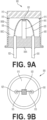
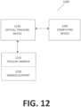
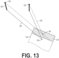
- a fiducial marker 800 may comprise a housing 805, an exit window 810, and a light source 815 and may be used in conjunction with a stereo optical tracking device 820 comprising optical sensors 825 to triangulate the location of the light source 815.
- a stereo optical tracking device 820 comprising optical sensors 825 to triangulate the location of the light source 815.
- light rays 830 when light rays 830 are emitted by the light source 815, they may undergo refraction 830A as they pass through the exit window 810 before the exiting light rays 830B reach the optical sensors 825.
- the light rays 830 do not form continuous straight lines and the amount of refraction 830A also varies based on the optical properties of the exit window 810 and the tilt angulation of the fiducial marker 800 with respect to each optical sensor 825.
- the computed location 840 of the light source 815 may be off by a significant margin from the true location. Accordingly, large metrological errors in the computation may result in unacceptable localization inaccuracy.
- Document US 2017/165006 A1 discloses a tracking device for use in a navigation system.
- the tracking device comprises a tracking head and a plurality of emitters supported by the tracking head to emit light.
- a plurality of dome-shaped lenses having arcuate inner and outer surfaces define an outer wall of uniform thickness disposed over the emitters so that light is emitted through the outer wall in a manner that minimizes light refraction.
- the invention as defined in claim 1 relates to an optical tracking system.
- the optical tracking system comprises an autoclavable fiducial marker assembly comprising: an opaque housing defining an interior cavity, a light emitting semiconductor die disposed in the interior cavity and in electrical communication with an anode and a cathode, a window panel joined to the opaque housing to enclose the interior cavity between the window panel and the opaque housing, the window panel configured to refract a plurality of light rays emitted by the light emitting semiconductor die, and a metallized coating forming a hermetic seal at an interface of the window panel and the opaque housing, wherein the fiducial marker assembly is configured to shield a peripheral edge of the window panel from the plurality of light rays; a tracking device comprising at least two optical sensors, each optical sensor configured to detect a position of a light ray of the plurality of light rays; a processor; and a non-transitory, computer-readable medium storing instructions that, when executed, cause the processor to: receive the position
- the anode and the cathode extend through the opaque housing.
- the opaque housing defines a notch configured to receive the window panel.
- the fiducial marker assembly further comprises a rod supporting the light emitting semiconductor die proximate the window panel.
- the rod comprises a heat sink configured to discharge heat from the light emitting semiconductor die.
- a diameter of the light emitting semiconductor die is greater than or equal to a diameter of the rod.
- a thermal expansion coefficient of each of the opaque housing, the window panel, and the rod are substantially equal.
- the opaque housing comprises a nickel-cobalt ferrous alloy; the window panel comprises an aluminum oxide; and the rod comprises a nickel-cobalt ferrous alloy.
- the metallized coating forms a ring extending radially inward from the interface to cover a portion of the window panel, wherein the ring is configured to shield the peripheral edge of the window panel from the plurality of light rays.
- the metallized coating comprises solder.
- the anode and the cathode extend through the opaque housing.
- the window panel defines a notch configured to secure the light emitting diode within a marker support.
- the window panel comprises a light-absorbing layer affixed on an interior face of the window panel facing the metallized coating.
- the window panel comprises an aluminum oxide.
- the opaque housing comprises a nickel-cobalt ferrous alloy.
- a method of tracking an object comprises coupling a fiducial marker assembly to the object, wherein the fiducial marker assembly comprises: an opaque housing defining an interior cavity, a light emitting semiconductor die disposed in the interior cavity and in electrical communication with an anode and a cathode, a window panel joined to the opaque housing to enclose the interior cavity between the window panel and the opaque housing, the window panel configured to refract a plurality of light rays emitted by the light emitting semiconductor die, and a metallized coating forming a hermetic seal at an interface of the window panel and the opaque housing, wherein the fiducial marker assembly is configured to shield a peripheral edge of the window panel from the plurality of light rays; detecting, by each of two or more optical sensors, a position of a light ray of the plurality of light rays; receiving, by a processor, the detected position of the light ray from each of the two or more optical sensors; adjusting, by the processor,
- the term "implant” is used to refer to a prosthetic device or structure manufactured to replace or enhance a biological structure.
- a prosthetic acetabular cup (implant) is used to replace or enhance a patients worn or damaged acetabulum.
- implant is generally considered to denote a man-made structure (as contrasted with a transplant), for the purposes of this specification an implant can include a biological tissue or material transplanted to replace or enhance a biological structure.
- real-time is used to refer to calculations or operations performed on-the-fly as events occur or input is received by the operable system.
- real-time is not intended to preclude operations that cause some latency between input and response, so long as the latency is an unintended consequence induced by the performance characteristics of the machine.
- NAVIO is a registered trademark of BLUE BELT TECHNOLOGIES, INC. of Pittsburgh, PA, which is a subsidiary of SMITH & NEPHEW, INC. of Memphis, TN.
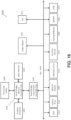
- FIG. 1 provides an illustration of an example computer-assisted surgical system (CASS) 100, according to some embodiments.
- the CASS uses computers, robotics, and imaging technology to aid surgeons in performing orthopedic surgery procedures such as total knee arthroplasty (TKA) or total hip arthroplasty (THA).
- TKA total knee arthroplasty
- THA total hip arthroplasty
- surgical navigation systems can aid surgeons in locating patient anatomical structures, guiding surgical instruments, and implanting medical devices with a high degree of accuracy.
- Surgical navigation systems such as the CASS 100 often employ various forms of computing technology to perform a wide variety of standard and minimally invasive surgical procedures and techniques.
- these systems allow surgeons to more accurately plan, track and navigate the placement of instruments and implants relative to the body of a patient, as well as conduct pre-operative and intra-operative body imaging.
- An Effector Platform 105 positions surgical tools relative to a patient during surgery.
- the exact components of the Effector Platform 105 will vary, depending on the embodiment employed.
- the Effector Platform 105 may include an End Effector 105B that holds surgical tools or instruments during their use.
- the End Effector 105B may be a handheld device or instrument used by the surgeon (e.g., a NAVIO ® hand piece or a cutting guide or jig) or, alternatively, the End Effector 105B can include a device or instrument held or positioned by a Robotic Arm 105A. While one Robotic Arm 105A is illustrated in FIG. 1 , in some embodiments there may be multiple devices.
- the Robotic Arm 105A may be mounted directly to the table T, be located next to the table T on a floor platform (not shown), mounted on a floor-to-ceiling pole, or mounted on a wall or ceiling of an operating room.
- the floor platform may be fixed or moveable.
- the robotic arm 105A is mounted on a floor-to-ceiling pole located between the patient's legs or feet.
- the End Effector 105B may include a suture holder or a stapler to assist in closing wounds.
- the surgical computer 150 can drive the robotic arms 105A to work together to suture the wound at closure.
- the surgical computer 150 can drive one or more robotic arms 105A to staple the wound at closure.
- the Effector Platform 105 can include a Limb Positioner 105C for positioning the patient's limbs during surgery.
- a Limb Positioner 105C is the SMITH AND NEPHEW SPIDER2 system.
- the Limb Positioner 105C may be operated manually by the surgeon or alternatively change limb positions based on instructions received from the Surgical Computer 150 (described below). While one Limb Positioner 105C is illustrated in FIG. 1 , in some embodiments there may be multiple devices. As examples, there may be one Limb Positioner 105C on each side of the operating table T or two devices on one side of the table T.
- the Limb Positioner 105C may be mounted directly to the table T, be located next to the table T on a floor platform (not shown), mounted on a pole, or mounted on a wall or ceiling of an operating room.
- the Limb Positioner 105C can be used in non-conventional ways, such as a retractor or specific bone holder.
- the Limb Positioner 105C may include, as examples, an ankle boot, a soft tissue clamp, a bone clamp, or a soft-tissue retractor spoon, such as a hooked, curved, or angled blade.
- the Limb Positioner 105C may include a suture holder to assist in closing wounds.
- the Effector Platform 105 may include tools, such as a screwdriver, light or laser, to indicate an axis or plane, bubble level, pin driver, pin puller, plane checker, pointer, finger, or some combination thereof.
- tools such as a screwdriver, light or laser, to indicate an axis or plane, bubble level, pin driver, pin puller, plane checker, pointer, finger, or some combination thereof.
- Resection Equipment 110 performs bone or tissue resection using, for example, mechanical, ultrasonic, or laser techniques.
- Resection Equipment 110 include drilling devices, burring devices, oscillatory sawing devices, vibratory impaction devices, reamers, ultrasonic bone cutting devices, radio frequency ablation devices, reciprocating devices (such as a rasp or broach), and laser ablation systems.
- the Resection Equipment 110 is held and operated by the surgeon during surgery.
- the Effector Platform 105 may be used to hold the Resection Equipment 110 during use.
- the Effector Platform 105 also can include a cutting guide or jig 105D that is used to guide saws or drills used to resect tissue during surgery.
- Such cutting guides 105D can be formed integrally as part of the Effector Platform 105 or Robotic Arm 105A, or cutting guides can be separate structures that can be matingly and/or removably attached to the Effector Platform 105 or Robotic Arm 105A.
- the Effector Platform 105 or Robotic Arm 105A can be controlled by the CASS 100 to position a cutting guide or jig 105D adjacent to the patient's anatomy in accordance with a pre-operatively or intraoperatively developed surgical plan such that the cutting guide or jig will produce a precise bone cut in accordance with the surgical plan.
- the Tracking System 115 uses one or more sensors to collect real-time position data that locates the patient's anatomy and surgical instruments. For example, for TKA procedures, the Tracking System may provide a location and orientation of the End Effector 105B during the procedure. In addition to positional data, data from the Tracking System 115 also can be used to infer velocity/acceleration of anatomy/instrumentation, which can be used for tool control. In some embodiments, the Tracking System 115 may use a tracker array attached to the End Effector 105B to determine the location and orientation of the End Effector 105B.
- imaging devices may be of suitable resolution or have a suitable perspective on the scene to pick up information stored in quick response (QR) codes or barcodes. This can be helpful in identifying specific objects not manually registered with the system.
- the camera may be mounted on the Robotic Arm 105A.
- EM based tracking devices include one or more wire coils and a reference field generator.
- the one or more wire coils may be energized (e.g., via a wired or wireless power supply). Once energized, the coil creates an electromagnetic field that can be detected and measured (e.g., by the reference field generator or an additional device) in a manner that allows for the location and orientation of the one or more wire coils to be determined.
- a single coil such as is shown in FIG. 2 , is limited to detecting five (5) total degrees-of-freedom (DOF).
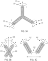
- a three coil system such as that shown in FIG. 3A is used to enable tracking in all six degrees of freedom that are possible for a rigid body moving in a three-dimensional space (i.e., forward/backward 310, up/down 320, left/right 330, roll 340, pitch 350, and yaw 360).
- the inclusion of two additional coils and the 90° offset angles at which they are positioned may require the tracking device to be much larger.
- less than three full coils may be used to track all 6DOF.
- two coils may be affixed to each other, such as is shown in FIG. 3B . Because the two coils 301B and 302B are rigidly affixed to each other, not perfectly parallel, and have locations that are known relative to each other, it is possible to determine the sixth degree of freedom 303B with this arrangement.
- two 5DOF EM sensors may be inserted into the patient (e.g., in a patient bone) at different locations and with different angular orientations (e.g., angle 303C is non-zero).
- specific objects can be manually registered by a surgeon with the system preoperatively or intraoperatively. For example, by interacting with a user interface, a surgeon may identify the starting location for a tool or a bone structure. By tracking fiducial marks associated with that tool or bone structure, or by using other conventional image tracking modalities, a processor may track that tool or bone as it moves through the environment in a three-dimensional model.
- certain markers such as fiducial marks that identify individuals, important tools, or bones in the theater may include passive or active identifiers that can be picked up by a camera or camera array associated with the tracking system.
- an IR LED can flash a pattern that conveys a unique identifier to the source of that pattern, providing a dynamic identification mark.
- one or two dimensional optical codes can be affixed to objects in the theater to provide passive identification that can occur based on image analysis. If these codes are placed asymmetrically on an object, they also can be used to determine an orientation of an object by comparing the location of the identifier with the extents of an object in an image.
- a QR code may be placed in a corner of a tool tray, allowing the orientation and identity of that tray to be tracked.
- Other tracking modalities are explained throughout.
- augmented reality headsets can be worn by surgeons and other staff to provide additional camera angles and tracking capabilities.
- certain features of objects can be tracked by registering physical properties of the object and associating them with objects that can be tracked, such as fiducial marks fixed to a tool or bone.
- objects such as fiducial marks fixed to a tool or bone.
- a surgeon may perform a manual registration process whereby a tracked tool and a tracked bone can be manipulated relative to one another.
- a three-dimensional surface can be mapped for that bone that is associated with a position and orientation relative to the frame of reference of that fiducial mark.
- a model of that surface can be tracked with an environment through extrapolation.
- the registration process that registers the CASS 100 to the relevant anatomy of the patient also can involve the use of anatomical landmarks, such as landmarks on a bone or cartilage.
- the CASS 100 can include a 3D model of the relevant bone or joint and the surgeon can intraoperatively collect data regarding the location of bony landmarks on the patient's actual bone using a probe that is connected to the CASS.
- Bony landmarks can include, for example, the medial malleolus and lateral malleolus, the ends of the proximal femur and distal tibia, and the center of the hip joint.
- the CASS 100 can compare and register the location data of bony landmarks collected by the surgeon with the probe with the location data of the same landmarks in the 3D model.
- the CASS 100 can construct a 3D model of the bone or joint without pre-operative image data by using location data of bony landmarks and the bone surface that are collected by the surgeon using a CASS probe or other means.
- the registration process also can include determining various axes of a joint.
- the surgeon can use the CASS 100 to determine the anatomical and mechanical axes of the femur and tibia.
- the surgeon and the CASS 100 can identify the center of the hip joint by moving the patient's leg in a spiral direction (i.e., circumduction) so the CASS can determine where the center of the hip joint is located.
- a Tissue Navigation System 120 (not shown in FIG. 1 ) provides the surgeon with intraoperative, real-time visualization for the patient's bone, cartilage, muscle, nervous, and/or vascular tissues surrounding the surgical area.
- tissue navigation examples include fluorescent imaging systems and ultrasound systems.
- the Display 125 provides graphical user interfaces (GUIs) that display images collected by the Tissue Navigation System 120 as well other information relevant to the surgery.
- GUIs graphical user interfaces
- the Display 125 overlays image information collected from various modalities (e.g., CT, MRI, X-ray, fluorescent, ultrasound, etc.) collected pre-operatively or intra-operatively to give the surgeon various views of the patient's anatomy as well as real-time conditions.
- the Display 125 may include, for example, one or more computer monitors.
- one or more members of the surgical staff may wear an Augmented Reality (AR) Head Mounted Device (HMD).
- AR Augmented Reality
- FIG. 1 the Surgeon 111 is wearing an AR HMD 155 that may, for example, overlay pre-operative image data on the patient or provide surgical planning suggestions.
- AR HMD 155 may, for example, overlay pre-operative image data on the patient or provide surgical planning suggestions.
- Surgical Computer 150 provides control instructions to various components of the CASS 100, collects data from those components, and provides general processing for various data needed during surgery.
- the Surgical Computer 150 is a general purpose computer.
- the Surgical Computer 150 may be a parallel computing platform that uses multiple central processing units (CPUs) or graphics processing units (GPU) to perform processing.
- the Surgical Computer 150 is connected to a remote server over one or more computer networks (e.g., the Internet).
- the remote server can be used, for example, for storage of data or execution of computationally intensive processing tasks.
- the computers can connect to the Surgical Computer 150 using a mix of technologies.
- the End Effector 105B may connect to the Surgical Computer 150 over a wired (i.e., serial) connection.
- the Tracking System 115, Tissue Navigation System 120, and Display 125 can similarly be connected to the Surgical Computer 150 using wired connections.
- the Tracking System 115, Tissue Navigation System 120, and Display 125 may connect to the Surgical Computer 150 using wireless technologies such as, without limitation, Wi-Fi, Bluetooth, Near Field Communication (NFC), or ZigBee.
- the CASS 100 may include a powered impaction device.
- Impaction devices are designed to repeatedly apply an impaction force that the surgeon can use to perform activities such as implant alignment.
- a surgeon will often insert a prosthetic acetabular cup into the implant host's acetabulum using an impaction device.
- impaction devices can be manual in nature (e.g., operated by the surgeon striking an impactor with a mallet), powered impaction devices are generally easier and quicker to use in the surgical setting.
- Powered impaction devices may be powered, for example, using a battery attached to the device. Various attachment pieces may be connected to the powered impaction device to allow the impaction force to be directed in various ways as needed during surgery. Also, in the context of hip surgeries, the CASS 100 may include a powered, robotically controlled end effector to ream the acetabulum to accommodate an acetabular cup implant.
- the patient's anatomy can be registered to the CASS 100 using CT or other image data, the identification of anatomical landmarks, tracker arrays attached to the patient's bones, and one or more cameras.
- Tracker arrays can be mounted on the iliac crest using clamps and/or bone pins and such trackers can be mounted externally through the skin or internally (either posterolaterally or anterolaterally) through the incision made to perform the THA.
- the CASS 100 can utilize one or more femoral cortical screws inserted into the proximal femur as checkpoints to aid in the registration process.
- the CASS 100 also can utilize one or more checkpoint screws inserted into the pelvis as additional checkpoints to aid in the registration process.
- Femoral tracker arrays can be secured to or mounted in the femoral cortical screws.
- the CASS 100 can employ steps where the registration is verified using a probe that the surgeon precisely places on key areas of the proximal femur and pelvis identified for the surgeon on the display 125.
- Trackers can be located on the robotic arm 105A or end effector 105B to register the arm and/or end effector to the CASS 100.
- the verification step also can utilize proximal and distal femoral checkpoints.
- the CASS 100 can utilize color prompts or other prompts to inform the surgeon that the registration process for the relevant bones and the robotic arm 105A or end effector 105B has been verified to a certain degree of accuracy (e.g., within 1mm).
- the CASS 100 can include a broach tracking option using femoral arrays to allow the surgeon to intraoperatively capture the broach position and orientation and calculate hip length and offset values for the patient. Based on information provided about the patient's hip joint and the planned implant position and orientation after broach tracking is completed, the surgeon can make modifications or adjustments to the surgical plan.
- the CASS 100 can include one or more powered reamers connected or attached to a robotic arm 105A or end effector 105B that prepares the pelvic bone to receive an acetabular implant according to a surgical plan.
- the robotic arm 105A and/or end effector 105B can inform the surgeon and/or control the power of the reamer to ensure that the acetabulum is being resected (reamed) in accordance with the surgical plan. For example, if the surgeon attempts to resect bone outside of the boundary of the bone to be resected in accordance with the surgical plan, the CASS 100 can power off the reamer or instruct the surgeon to power off the reamer.
- the CASS 100 can provide the surgeon with an option to turn off or disengage the robotic control of the reamer.
- the display 125 can depict the progress of the bone being resected (reamed) as compared to the surgical plan using different colors.
- the surgeon can view the display of the bone being resected (reamed) to guide the reamer to complete the reaming in accordance with the surgical plan.
- the CASS 100 can provide visual or audible prompts to the surgeon to warn the surgeon that resections are being made that are not in accordance with the surgical plan.
- the CASS 100 can employ a manual or powered impactor that is attached or connected to the robotic arm 105A or end effector 105B to impact trial implants and final implants into the acetabulum.
- the robotic arm 105A and/or end effector 105B can be used to guide the impactor to impact the trial and final implants into the acetabulum in accordance with the surgical plan.
- the CASS 100 can cause the position and orientation of the trial and final implants vis-à-vis the bone to be displayed to inform the surgeon as to how the trial and final implant's orientation and position compare to the surgical plan, and the display 125 can show the implant's position and orientation as the surgeon manipulates the leg and hip.
- the CASS 100 can provide the surgeon with the option of re-planning and re-doing the reaming and implant impaction by preparing a new surgical plan if the surgeon is not satisfied with the original implant position and orientation.
- the CASS 100 can develop a proposed surgical plan based on a three dimensional model of the hip joint and other information specific to the patient, such as the mechanical and anatomical axes of the leg bones, the epicondylar axis, the femoral neck axis, the dimensions (e.g., length) of the femur and hip, the midline axis of the hip joint, the ASIS axis of the hip joint, and the location of anatomical landmarks such as the lesser trochanter landmarks, the distal landmark, and the center of rotation of the hip joint.
- the CASS-developed surgical plan can provide a recommended optimal implant size and implant position and orientation based on the three dimensional model of the hip joint and other information specific to the patient.
- the CASS-developed surgical plan can include proposed details on offset values, inclination and anteversion values, center of rotation, cup size, medialization values, superior-inferior fit values, femoral stem sizing and length.
- the CASS-developed surgical plan can be viewed preoperatively and intraoperatively, and the surgeon can modify CASS-developed surgical plan preoperatively or intraoperatively.
- the CASS-developed surgical plan can display the planned resection to the hip joint and superimpose the planned implants onto the hip joint based on the planned resections.
- the CASS 100 can provide the surgeon with options for different surgical workflows that will be displayed to the surgeon based on a surgeon's preference. For example, the surgeon can choose from different workflows based on the number and types of anatomical landmarks that are checked and captured and/or the location and number of tracker arrays used in the registration process.
- a powered impaction device used with the CASS 100 may operate with a variety of different settings.
- the surgeon adjusts settings through a manual switch or other physical mechanism on the powered impaction device.
- a digital interface may be used that allows setting entry, for example, via a touchscreen on the powered impaction device. Such a digital interface may allow the available settings to vary based, for example, on the type of attachment piece connected to the power attachment device.
- the settings can be changed through communication with a robot or other computer system within the CASS 100. Such connections may be established using, for example, a Bluetooth or Wi-Fi networking module on the powered impaction device.
- the impaction device and end pieces may contain features that allow the impaction device to be aware of what end piece (cup impactor, broach handle, etc.) is attached with no action required by the surgeon, and adjust the settings accordingly. This may be achieved, for example, through a QR code, barcode, RFID tag, or other method.
- the settings include cup impaction settings (e.g., single direction, specified frequency range, specified force and/or energy range); broach impaction settings (e.g., dual direction/oscillating at a specified frequency range, specified force and/or energy range); femoral head impaction settings (e.g., single direction/single blow at a specified force or energy); and stem impaction settings (e.g., single direction at specified frequency with a specified force or energy).
- the powered impaction device includes settings related to acetabular liner impaction (e.g., single direction/single blow at a specified force or energy).
- the powered impaction device may offer settings for different bone quality based on preoperative testing/imaging/knowledge and/or intraoperative assessment by surgeon.
- the powered impactor device may have a dual function. For example, the powered impactor device not only could provide reciprocating motion to provide an impact force, but also could provide reciprocating motion for a broach or rasp.
- the powered impaction device includes feedback sensors that gather data during instrument use and send data to a computing device, such as a controller within the device or the Surgical Computer 150.
- This computing device can then record the data for later analysis and use.
- Examples of the data that may be collected include, without limitation, sound waves, the predetermined resonance frequency of each instrument, reaction force or rebound energy from patient bone, location of the device with respect to imaging (e.g., fluoro, CT, ultrasound, MRI, etc.) registered bony anatomy, and/or external strain gauges on bones.
- the computing device may execute one or more algorithms in real-time or near real-time to aid the surgeon in performing the surgical procedure. For example, in some embodiments, the computing device uses the collected data to derive information such as the proper final broach size (femur); when the stem is fully seated (femur side); or when the cup is seated (depth and/or orientation) for a THA. Once the information is known, it may be displayed for the surgeon's review, or it may be used to activate haptics or other feedback mechanisms to guide the surgical procedure.
- information such as the proper final broach size (femur); when the stem is fully seated (femur side); or when the cup is seated (depth and/or orientation) for a THA.
- the data derived from the aforementioned algorithms may be used to drive operation of the device.
- the device may automatically extend an impaction head (e.g., an end effector) moving the implant into the proper location, or turn the power off to the device once the implant is fully seated.
- the derived information may be used to automatically adjust settings for quality of bone where the powered impaction device should use less power to mitigate femoral/acetabular/pelvic fracture or damage to surrounding tissues.
- the CASS 100 includes a robotic arm 105A that serves as an interface to stabilize and hold a variety of instruments used during the surgical procedure.
- these instruments may include, without limitation, retractors, a sagittal or reciprocating saw, the reamer handle, the cup impactor, the broach handle, and the stem inserter.
- the robotic arm 105A may have multiple degrees of freedom (like a Spider device), and have the ability to be locked in place (e.g., by a press of a button, voice activation, a surgeon removing a hand from the robotic arm, or other method).
- movement of the robotic arm 105A may be effectuated by use of a control panel built into the robotic arm system.
- a display screen may include one or more input sources, such as physical buttons or a user interface having one or more icons, that direct movement of the robotic arm 105A.
- the surgeon or other healthcare professional may engage with the one or more input sources to position the robotic arm 105A when performing a surgical procedure.
- a tool or an end effector 105B attached or integrated into a robotic arm 105A may include, without limitation, a burring device, a scalpel, a cutting device, a retractor, a joint tensioning device, or the like.
- the end effector may be positioned at the end of the robotic arm 105A such that any motor control operations are performed within the robotic arm system.
- the tool may be secured at a distal end of the robotic arm 105A, but motor control operation may reside within the tool itself.
- the robotic arm 105A may be motorized internally to both stabilize the robotic arm, thereby preventing it from falling and hitting the patient, surgical table, surgical staff, etc., and to allow the surgeon to move the robotic arm without having to fully support its weight. While the surgeon is moving the robotic arm 105A, the robotic arm may provide some resistance to prevent the robotic arm from moving too fast or having too many degrees of freedom active at once.
- the position and the lock status of the robotic arm 105A may be tracked, for example, by a controller or the Surgical Computer 150.
- the robotic arm 105A can be moved by hand (e.g., by the surgeon) or with internal motors into its ideal position and orientation for the task being performed.
- the robotic arm 105A may be enabled to operate in a "free" mode that allows the surgeon to position the arm into a desired position without being restricted. While in the free mode, the position and orientation of the robotic arm 105A may still be tracked as described above. In one embodiment, certain degrees of freedom can be selectively released upon input from user (e.g., surgeon) during specified portions of the surgical plan tracked by the Surgical Computer 150.
- a robotic arm 105A or end effector 105B can include a trigger or other means to control the power of a saw or drill. Engagement of the trigger or other means by the surgeon can cause the robotic arm 105A or end effector 105B to transition from a motorized alignment mode to a mode where the saw or drill is engaged and powered on.
- the CASS 100 can include a foot pedal (not shown) that causes the system to perform certain functions when activated. For example, the surgeon can activate the foot pedal to instruct the CASS 100 to place the robotic arm 105A or end effector 105B in an automatic mode that brings the robotic arm or end effector into the proper position with respect to the patient's anatomy in order to perform the necessary resections.
- the CASS 100 also can place the robotic arm 105A or end effector 105B in a collaborative mode that allows the surgeon to manually manipulate and position the robotic arm or end effector into a particular location.
- the collaborative mode can be configured to allow the surgeon to move the robotic arm 105A or end effector 105B medially or laterally, while restricting movement in other directions.
- the robotic arm 105A or end effector 105B can include a cutting device (saw, drill, and burr) or a cutting guide or jig 105D that will guide a cutting device.
- movement of the robotic arm 105A or robotically controlled end effector 105B can be controlled entirely by the CASS 100 without any, or with only minimal, assistance or input from a surgeon or other medical professional.
- the movement of the robotic arm 105A or robotically controlled end effector 105B can be controlled remotely by a surgeon or other medical professional using a control mechanism separate from the robotic arm or robotically controlled end effector device, for example using a joystick or interactive monitor or display control device.
- a robotic arm 105A may be used for holding the retractor.
- the robotic arm 105A may be moved into the desired position by the surgeon. At that point, the robotic arm 105A may lock into place.
- the robotic arm 105A is provided with data regarding the patient's position, such that if the patient moves, the robotic arm can adjust the retractor position accordingly.
- multiple robotic arms may be used, thereby allowing multiple retractors to be held or for more than one activity to be performed simultaneously (e.g., retractor holding & reaming).
- the robotic arm 105A may also be used to help stabilize the surgeon's hand while making a femoral neck cut.
- control of the robotic arm 105A may impose certain restrictions to prevent soft tissue damage from occurring.
- the Surgical Computer 150 tracks the position of the robotic arm 105A as it operates. If the tracked location approaches an area where tissue damage is predicted, a command may be sent to the robotic arm 105A causing it to stop.
- the robotic arm 105A is automatically controlled by the Surgical Computer 150, the Surgical Computer may ensure that the robotic arm is not provided with any instructions that cause it to enter areas where soft tissue damage is likely to occur.
- the Surgical Computer 150 may impose certain restrictions on the surgeon to prevent the surgeon from reaming too far into the medial wall of the acetabulum or reaming at an incorrect angle or orientation.
- the robotic arm 105A may be used to hold a cup impactor at a desired angle or orientation during cup impaction. When the final position has been achieved, the robotic arm 105A may prevent any further seating to prevent damage to the pelvis.
- the surgeon may use the robotic arm 105A to position the broach handle at the desired position and allow the surgeon to impact the broach into the femoral canal at the desired orientation.
- the robotic arm 105A may restrict the handle to prevent further advancement of the broach.
- the robotic arm 105A may also be used for resurfacing applications.
- the robotic arm 105A may stabilize the surgeon while using traditional instrumentation and provide certain restrictions or limitations to allow for proper placement of implant components (e.g., guide wire placement, chamfer cutter, sleeve cutter, plan cutter, etc.).
- implant components e.g., guide wire placement, chamfer cutter, sleeve cutter, plan cutter, etc.
- the robotic arm 105A may stabilize the surgeon's handpiece and may impose restrictions on the handpiece to prevent the surgeon from removing unintended bone in contravention of the surgical plan.
- the robotic arm 105A may be a passive arm.
- the robotic arm 105A may be a CIRQ robot arm available from Brainlab AG.
- CIRQ is a registered trademark of Brainlab AG, Olof-Palme-Str. 9 81829, Ober, FED REP of GERMANY.
- the robotic arm 105A is an intelligent holding arm as disclosed in U.S. Patent Application No. 15/525,585 to Krinninger et al. , U.S. Patent Application No. 15/561,042 to Nowatschin et al. , U.S. Patent Application No. 15/561,048 to Nowatschin et al. , and U.S. Patent No. 10,342,636 to Nowatschin et al .
- the various services that are provided by medical professionals to treat a clinical condition are collectively referred to as an "episode of care.”
- the episode of care can include three phases: pre-operative, intra-operative, and post-operative.
- data is collected or generated that can be used to analyze the episode of care in order to understand various features of the procedure and identify patterns that may be used, for example, in training models to make decisions with minimal human intervention.
- the data collected over the episode of care may be stored at the Surgical Computer 150 or the Surgical Data Server 180 as a complete dataset.
- a dataset exists that comprises all of the data collectively pre-operatively about the patient, all of the data collected or stored by the CASS 100 intra-operatively, and any post-operative data provided by the patient or by a healthcare professional monitoring the patient.
- the data collected during the episode of care may be used to enhance performance of the surgical procedure or to provide a holistic understanding of the surgical procedure and the patient outcomes.
- the data collected over the episode of care may be used to generate a surgical plan.
- a high-level, pre-operative plan is refined intra-operatively as data is collected during surgery.
- the surgical plan can be viewed as dynamically changing in real-time or near real-time as new data is collected by the components of the CASS 100.
- pre-operative images or other input data may be used to develop a robust plan preoperatively that is simply executed during surgery.
- the data collected by the CASS 100 during surgery may be used to make recommendations that ensure that the surgeon stays within the pre-operative surgical plan. For example, if the surgeon is unsure how to achieve a certain prescribed cut or implant alignment, the Surgical Computer 150 can be queried for a recommendation.
- the pre-operative and intra-operative planning approaches can be combined such that a robust pre-operative plan can be dynamically modified, as necessary or desired, during the surgical procedure.
- a biomechanics-based model of patient anatomy contributes simulation data to be considered by the CASS 100 in developing preoperative, intraoperative, and post-operative/rehabilitation procedures to optimize implant performance outcomes for the patient.
- implants can be designed using episode of care data.
- Example data-driven techniques for designing, sizing, and fitting implants are described in U.S. Patent Application No. 13/814,531 filed August 15, 2011 and entitled “Systems and Methods for Optimizing Parameters for Orthopaedic Procedures"; U.S. Patent Application No. 14/232,958 filed July 20, 2012 and entitled “Systems and Methods for Optimizing Fit of an Implant to Anatomy”; and U.S. Patent Application No. 12/234,444 filed September 19, 2008 and entitled “Operatively Tuning Implants for Increased Performance”.
- the data can be used for educational, training, or research purposes.
- other doctors or students can remotely view surgeries in interfaces that allow them to selectively view data as it is collected from the various components of the CASS 100.
- similar interfaces may be used to "playback" a surgery for training or other educational purposes, or to identify the source of any issues or complications with the procedure.
- pre-surgery patients use a mobile application ("app") to answer questionnaires regarding their current quality of life.
- preoperative data used by the CASS 100 includes demographic, anthropometric, cultural, or other specific traits about a patient that can coincide with activity levels and specific patient activities to customize the surgical plan to the patient. For example, certain cultures or demographics may be more likely to use a toilet that requires squatting on a daily basis.
- FIG. 5A shows examples of some of the control instructions that the Surgical Computer 150 provides to other components of the CASS 100, according to some embodiments. Note that the example of FIG. 5A assumes that the components of the Effector Platform 105 are each controlled directly by the Surgical Computer 150. In embodiments where a component is manually controlled by the Surgeon 111, instructions may be provided on the Display 125 or AR HMD 155 instructing the Surgeon 111 how to move the component.
- the various components included in the Effector Platform 105 are controlled by the Surgical Computer 150 providing position commands that instruct the component where to move within a coordinate system.
- the Surgical Computer 150 provides the Effector Platform 105 with instructions defining how to react when a component of the Effector Platform 105 deviates from a surgical plan. These commands are referenced in FIG. 5A as "haptic" commands.
- the End Effector 105B may provide a force to resist movement outside of an area where resection is planned.
- Other commands that may be used by the Effector Platform 105 include vibration and audio cues.
- the end effectors 105B of the robotic arm 105A are operatively coupled with cutting guide 105D.
- the robotic arm 105A can move the end effectors 105B and the cutting guide 105D into position to match the location of the femoral or tibial cut to be performed in accordance with the surgical plan. This can reduce the likelihood of error, allowing the vision system and a processor utilizing that vision system to implement the surgical plan to place a cutting guide 105D at the precise location and orientation relative to the tibia or femur to align a cutting slot of the cutting guide with the cut to be performed according to the surgical plan.
- the cutting guide 105D may include one or more pin holes that are used by a surgeon to drill and screw or pin the cutting guide into place before performing a resection of the patient tissue using the cutting guide. This can free the robotic arm 105A or ensure that the cutting guide 105D is fully affixed without moving relative to the bone to be resected. For example, this procedure can be used to make the first distal cut of the femur during a total knee arthroplasty.
- cutting guide 105D can be fixed to the femoral head or the acetabulum for the respective hip arthroplasty resection. It should be understood that any arthroplasty that utilizes precise cuts can use the robotic arm 105A and/or cutting guide 105D in this manner.
- the Resection Equipment 110 is provided with a variety of commands to perform bone or tissue operations. As with the Effector Platform 105, position information may be provided to the Resection Equipment 110 to specify where it should be located when performing resection. Other commands provided to the Resection Equipment 110 may be dependent on the type of resection equipment. For example, for a mechanical or ultrasonic resection tool, the commands may specify the speed and frequency of the tool. For Radiofrequency Ablation (RFA) and other laser ablation tools, the commands may specify intensity and pulse duration.
- RFA Radiofrequency Ablation
- the commands may specify intensity and pulse duration.
- Some components of the CASS 100 do not need to be directly controlled by the Surgical Computer 150; rather, the Surgical Computer 150 only needs to activate the component, which then executes software locally specifying the manner in which to collect data and provide it to the Surgical Computer 150.
- the Tracking System 115 and the Tissue Navigation System 120.
- the Surgical Computer 150 provides the Display 125 with any visualization that is needed by the Surgeon 111 during surgery.
- the Surgical Computer 150 may provide instructions for displaying images, GUIs, etc. using techniques known in the art.
- the display 125 can include various portions of the workflow of a surgical plan. During the registration process, for example, the display 125 can show a preoperatively constructed 3D bone model and depict the locations of the probe as the surgeon uses the probe to collect locations of anatomical landmarks on the patient.
- the display 125 can include information about the surgical target area. For example, in connection with a TKA, the display 125 can depict the mechanical and anatomical axes of the femur and tibia.
- the display 125 can depict varus and valgus angles for the knee joint based on a surgical plan, and the CASS 100 can depict how such angles will be affected if contemplated revisions to the surgical plan are made. Accordingly, the display 125 is an interactive interface that can dynamically update and display how changes to the surgical plan would impact the procedure and the final position and orientation of implants installed on bone.
- the display 125 can depict the planned or recommended bone cuts before any cuts are performed.
- the surgeon 111 can manipulate the image display to provide different anatomical perspectives of the target area and can have the option to alter or revise the planned bone cuts based on intraoperative evaluation of the patient.
- the display 125 can depict how the chosen implants would be installed on the bone if the planned bone cuts are performed. If the surgeon 111 choses to change the previously planned bone cuts, the display 125 can depict how the revised bone cuts would change the position and orientation of the implant when installed on the bone.
- the display 125 can provide the surgeon 111 with a variety of data and information about the patient, the planned surgical intervention, and the implants. Various patient-specific information can be displayed, including real-time data concerning the patient's health such as heart rate, blood pressure, etc.
- the display 125 also can include information about the anatomy of the surgical target region including the location of landmarks, the current state of the anatomy (e.g., whether any resections have been made, the depth and angles of planned and executed bone cuts), and future states of the anatomy as the surgical plan progresses.
- the display 125 also can provide or depict additional information about the surgical target region.
- the display 125 can provide information about the gaps (e.g., gap balancing) between the femur and tibia and how such gaps will change if the planned surgical plan is carried out.
- the display 125 can provide additional relevant information about the knee joint such as data about the joint's tension (e.g., ligament laxity) and information concerning rotation and alignment of the joint.
- the display 125 can depict how the planned implants' locations and positions will affect the patient as the knee joint is flexed.
- the display 125 can depict how the use of different implants or the use of different sizes of the same implant will affect the surgical plan and preview how such implants will be positioned on the bone.
- the CASS 100 can provide such information for each of the planned bone resections in a TKA or THA.
- the CASS 100 can provide robotic control for one or more of the planned bone resections.
- the CASS 100 can provide robotic control only for the initial distal femur cut, and the surgeon 111 can manually perform other resections (anterior, posterior and chamfer cuts) using conventional means, such as a 4-in-1 cutting guide or jig 105D.
- the display 125 can employ different colors to inform the surgeon of the status of the surgical plan. For example, un-resected bone can be displayed in a first color, resected bone can be displayed in a second color, and planned resections can be displayed in a third color. Implants can be superimposed onto the bone in the display 125, and implant colors can change or correspond to different types or sizes of implants.
- the information and options depicted on the display 125 can vary depending on the type of surgical procedure being performed. Further, the surgeon 111 can request or select a particular surgical workflow display that matches or is consistent with his or her surgical plan preferences. For example, for a surgeon 111 who typically performs the tibial cuts before the femoral cuts in a TKA, the display 125 and associated workflow can be adapted to take this preference into account. The surgeon 111 also can preselect that certain steps be included or deleted from the standard surgical workflow display.
- the surgical workflow display can be organized into modules, and the surgeon can select which modules to display and the order in which the modules are provided based on the surgeon's preferences or the circumstances of a particular surgery.
- Modules directed to ligament and gap balancing can include pre- and post-resection ligament/gap balancing, and the surgeon 111 can select which modules to include in their default surgical plan workflow depending on whether they perform such ligament and gap balancing before or after (or both) bone resections are performed.
- the Surgical Computer 150 may provide images, text, etc. using the data format supported by the equipment.
- the Display 125 is a holography device such as the Microsoft HoloLens TM or Magic Leap One TM
- the Surgical Computer 150 may use the HoloLens Application Program Interface (API) to send commands specifying the position and content of holograms displayed in the field of view of the Surgeon 111.
- API HoloLens Application Program Interface
- one or more surgical planning models may be incorporated into the CASS 100 and used in the development of the surgical plans provided to the surgeon 111.
- the term "surgical planning model” refers to software that simulates the biomechanics performance of anatomy under various scenarios to determine the optimal way to perform cutting and other surgical activities. For example, for knee replacement surgeries, the surgical planning model can measure parameters for functional activities, such as deep knee bends, gait, etc., and select cut locations on the knee to optimize implant placement.
- One example of a surgical planning model is the LIFEMOD TM simulation software from SMITH AND NEPHEW, INC.
- the Surgical Computer 150 includes computing architecture that allows full execution of the surgical planning model during surgery (e.g., a GPU-based parallel processing environment).
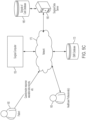
- the Surgical Computer 150 may be connected over a network to a remote computer that allows such execution, such as a Surgical Data Server 180 (see FIG. 5C ).
- a set of transfer functions are derived that simplify the mathematical operations captured by the model into one or more predictor equations. Then, rather than execute the full simulation during surgery, the predictor equations are used. Further details on the use of transfer functions are described in WIPO Publication No. 2020/037308, filed August 19, 2019.
- data is collected at a central location to provide for easier analysis and use.
- Data can be manually collected from various CASS components in some instances.
- a portable storage device e.g., USB stick
- the data can then be transferred, for example, via a desktop computer to the centralized storage.
- the Surgical Computer 150 is connected directly to the centralized storage via a Network 175 as shown in FIG. 5C .
- the Operative Patient Care System 620 employs a data collecting and management method to provide a detailed surgical case plan with distinct steps that are monitored and/or executed using a CASS 100.
- the performance of the user(s) is calculated at the completion of each step and can be used to suggest changes to the subsequent steps of the case plan.
- Case plan generation relies on a series of input data that is stored on a local or cloud-storage database. Input data can be related to both the current patient undergoing treatment and historical data from patients who have received similar treatment(s).
- This Healthcare Professional Data 625 may include, for example, a description of a known or preferred surgical technique (e.g., Cruciate Retaining (CR) vs Posterior Stabilized (PS), up- vs downsizing, tourniquet vs tourniquet-less, femoral stem style, preferred approach for THA, etc.), the level of training of the Healthcare Professional(s) 630 (e.g., years in practice, fellowship trained, where they trained, whose techniques they emulate), previous success level including historical data (outcomes, patient satisfaction), and the expected ideal outcome with respect to range of motion, days of recovery, and survivorship of the device.
- a known or preferred surgical technique e.g., Cruciate Retaining (CR) vs Posterior Stabilized (PS), up- vs downsizing, tourniquet vs tourniquet-less, femoral stem style, preferred approach for THA, etc.
- the level of training of the Healthcare Professional(s) 630 e
- the predictor equation and associated optimization can be used to generate the resection planes for use with a PSKI system.
- the predictor equation computation and optimization are completed prior to surgery.
- Patient anatomy is estimated using medical image data (x-ray, CT, MRI).
- Global optimization of the predictor equation can provide an ideal size and position of the implant components.
- Boolean intersection of the implant components and patient anatomy is defined as the resection volume.
- PSKI can be produced to remove the optimized resection envelope. In this embodiment, the surgeon cannot alter the surgical plan intraoperatively.
- predictions or recommendations made by the aforementioned machine learning models can be directly integrated into the surgical workflow.
- the Surgical Computer 150 may execute the machine learning model in the background making predictions or recommendations for upcoming actions or surgical conditions. A plurality of states can thus be predicted or recommended for each period.
- the Surgical Computer 150 may predict or recommend the state for the next 5 minutes in 30 second increments.
- the surgeon can utilize a "process display" view of the surgery that allows visualization of the future state.
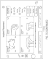
- FIG. 7C depicts a series of images that may be displayed to the surgeon depicting the implant placement interface.
- the surgeon could preview an entire surgery to confirm that the CASS-recommended plan meets the surgeon's expectations and/or requirements.
- the output of the machine learning model is the state of the CASS 100 itself, commands can be derived to control the components of the CASS to achieve each predicted state. In the extreme case, the entire surgery could thus be automated based on just the initial state information.
- an optically tracked point probe may be used to map the actual surface of the target bone that needs a new implant. Mapping is performed after removal of the defective or worn-out implant, as well as after removal of any diseased or otherwise unwanted bone. A plurality of points is collected on the bone surfaces by brushing or scraping the entirety of the remaining bone with the tip of the point probe. This is referred to as tracing or "painting" the bone. The collected points are used to create a three-dimensional model or surface map of the bone surfaces in the computerized planning system.
- the created 3D model of the remaining bone is then used as the basis for planning the procedure and necessary implant sizes.
- An alternative technique that uses X-rays to determine a 3D model is described in U.S. Patent Application No. 16/387,151, filed April 17, 2019 and entitled “Three-Dimensional Selective Bone Matching" and U.S. Patent Application No. 16/789,930, filed February 13, 2020 and entitled “Three-Dimensional Selective Bone Matching".
- the point probe painting can be used to acquire high resolution data in key areas such as the acetabular rim and acetabular fossa. This can allow a surgeon to obtain a detailed view before beginning to ream.
- the point probe may be used to identify the floor (fossa) of the acetabulum.
- the thickness of the area between the acetabulum and the medial wall could be estimated. For example, once the acetabular rim and acetabular fossa has been painted and registered to the pre-operative 3D model, the thickness can readily be estimated by comparing the location of the surface of the acetabulum to the location of the medial wall. Using this knowledge, the CASS 100 may provide alerts or other responses in the event that any surgical activity is predicted to protrude through the acetabular wall while reaming.
- the point probe may also be used to collect high resolution data of common reference points used in orienting the 3D model to the patient. For example, for pelvic plane landmarks like the ASIS and the pubic symphysis, the surgeon may use the point probe to paint the bone to represent a true pelvic plane. Given a more complete view of these landmarks, the registration software has more information to orient the 3D model.
- the point probe may also be used to collect high-resolution data describing the proximal femoral reference point that could be used to increase the accuracy of implant placement.
- GT Greater Trochanter
- the alignment is highly dependent on proper location of the GT; thus, in some embodiments, the point probe is used to paint the GT to provide a high-resolution view of the area.
- LT Lesser Trochanter
- the Dorr Classification helps to select a stem that will maximize the ability of achieving a press-fit during surgery to prevent micromotion of femoral components post-surgery and ensure optimal bony ingrowth.
- the Dorr Classification measures the ratio between the canal width at the LT and the canal width 10 cm below the LT. The accuracy of the classification is highly dependent on the correct location of the relevant anatomy. Thus, it may be advantageous to paint the LT to provide a high-resolution view of the area.
- the point probe is used to paint the femoral neck to provide high-resolution data that allows the surgeon to better understand where to make the neck cut.
- the navigation system can then guide the surgeon as they perform the neck cut.
- the femoral neck angle is measured by placing one line down the center of the femoral shaft and a second line down the center of the femoral neck.
- High-resolution femoral head neck data also could be used for a navigated resurfacing procedure where the software/hardware aids the surgeon in preparing the proximal femur and placing the femoral component.
- the femoral head and neck are not removed; rather, the head is trimmed and capped with a smooth metal covering.
- a 3D model is developed during the pre-operative stage based on 2D or 3D images of the anatomical area of interest.
- registration between the 3D model and the surgical site is performed prior to the surgical procedure.
- the registered 3D model may be used to track and measure the patient's anatomy and surgical tools intraoperatively.
- landmarks are acquired to facilitate registration of this pre-operative 3D model to the patient's anatomy.
- these points could comprise the femoral head center, distal femoral axis point, medial and lateral epicondyles, medial and lateral malleolus, proximal tibial mechanical axis point, and tibial A/P direction.
- these points could comprise the anterior superior iliac spine (ASIS), the pubic symphysis, points along the acetabular rim and within the hemisphere, the greater trochanter (GT), and the lesser trochanter (LT).
- ASIS anterior superior iliac spine
- GT greater trochanter
- LT lesser trochanter
- each pre-operative image is compared to a library of images showing "healthy" anatomy (i.e., without defects). Any significant deviations between the patient's images and the healthy images can be flagged as a potential defect. Then, during surgery, the surgeon can be warned of the possible defect via a visual alert on the display 125 of the CASS 100. The surgeon can then paint the area to provide further detail regarding the potential defect to the Surgical Computer 150.
- the surgeon may use a non-contact method for registration of bony anatomy intra-incision.
- laser scanning is employed for registration.
- a laser stripe is projected over the anatomical area of interest and the height variations of the area are detected as changes in the line.
- Other non-contact optical methods such as white light interferometry or ultrasound, may alternatively be used for surface height measurement or to register the anatomy.
- ultrasound technology may be beneficial where there is soft tissue between the registration point and the bone being registered (e.g., ASIS, pubic symphysis in hip surgeries), thereby providing for a more accurate definition of anatomic planes.
- fiducial markers comprising light emitting diodes (LEDs) to track the location of an object of interest, e.g., a patient bone or a surgical instrument.
- the LED emits light to be tracked by an optical tracking device and a computing device may determine the location of the object of interest based on continuous monitoring of the emitted light.
- standard LED housings are not suitable in this regard due to the use of autoclaving in typical sterilization procedures between uses.
- Autoclaving includes temperature cycles that place large mechanical stresses on the housing and may result in cracks in the housing. Further, steam cycles involved in autoclaving may lead to electrical failures, especially where the seal of the housing is breached. Transparency of the exit window also degrades due to the temperature and steam cycles, thus affecting metrological performance.
- the fiducial marker 900 may be a light emitting diode designed and configured to be autoclaved in accordance with standard medical sterilization procedures.
- the fiducial marker 900 may comprise an opaque housing 905, a window panel 910, a metallized coating 915, and a light emitting semiconductor die 920.
- the light emitting semiconductor die 920 may be connected to an anode 925 and a cathode 930 (e.g., via bond wires 935) that extend through a portion of the opaque housing 905.
- the fiducial marker 900 further comprises a support rod 940 for supporting the light emitting semiconductor die 920.
- FIG. 9A illustrates a side view of the fiducial marker 900.
- the opaque housing 905 may include a base 905A and a peripheral wall 905B that define an interior cavity 905C.
- the opaque housing 905 is substantially cylindrical.
- the peripheral wall 905B may form a hollow circular cross-section.
- the opaque housing 905 may form another shape.
- the base 905A and peripheral wall 905B are formed as a unitary body. However, in additional embodiments, the base 905A and the peripheral wall 905B are formed as separate components.
- the base 905A and the peripheral wall 905B may be formed from the same material or different materials and may be joined to form a fluid-tight seal capable of withstanding conditions associated with autoclaving.
- the base 905A and peripheral wall 905B may be joined by any technique known to a person having an ordinary level of skill in the art.
- the opaque housing 905 or individual components thereof comprise a material configured to be sealed to the window panel 910.
- the opaque housing 905 may be formed from Kovar, a nickel-cobalt ferrous alloy available from CRS Holdings, Inc. of Delaware, USA.
- Kovar is configured to have thermal expansion characteristics similar to glass in order to allow a tight mechanical joint to be formed between the Kovar material and glass, thereby avoiding stressing or cracking of the joint.
- the Kovar material of the opaque housing 905 may also be tailored or optimized to match the thermal expansion characteristics of the material of the window panel 910.
- the material and/or construction of the opaque housing 905 may be configured to optimize a thermal expansion coefficient of the opaque housing.
- the opaque housing 905 or individual components thereof may comprise additional or alternative materials having adjustable thermal expansion characteristics and/or being capable of forming a tight mechanical joint with the window panel 910.
- the anode 925 and the cathode 930 extend through the base 905A.
- the anode 925 and cathode 930 may each comprise a cylindrical rod extending through the base 905A.
- the anode 925 is oriented parallel to the cathode 930.
- additional shapes and configurations of the anode 925 and cathode 930 are contemplated herein.
- the anode 925 and/or the cathode 930 may be alternatively arranged on other portions of the opaque housing, e.g., the peripheral wall 905B.
- the anode 925 and cathode 930 may be formed as separate components from the base opaque housing 905.
- the anode 925 and cathode 930 may be formed from a different material than the opaque housing 905 and may be joined to form a fluid-tight seal capable of withstanding conditions associated with autoclaving.
- the anode 925 and cathode 930 may be joined to the opaque housing 905 by any technique known to a person having an ordinary level of skill in the art.
- the window panel 910 is joined to the opaque housing 905 to enclose the interior cavity 905C.
- the window panel 910 may be joined to an end of the peripheral wall 905B opposite the base 905A.
- the window panel 910 may be transparent in order to transmit light therethrough.
- the window panel 910 is fully or substantially transparent in order to minimize scattering and/or reflection of light as it passes through the window panel.
- the window panel 910 may be configured as semitransparent or translucent.
- the window panel 910 is a flat panel in order to simplify the optical effects on emitted light.
- the window panel 910 is formed as a glass from a variety of materials.
- the window panel 910 comprises aluminum oxide.
- the window panel 910 comprises aluminum(I) oxide (Al 2 O), aluminum(II) oxide (AlO), and/or aluminum(III) oxide (Al 2 O 3 ).
- the aluminum oxide(s) for the window panel 910 may be provided in a variety of forms.
- the aluminum oxide(s) may comprise alumina and/or corundum (e.g., sapphire, ruby, and the like). Additional or alternative materials may be used to form the window panel 910 to improve various characteristics of the window panel 910 as would be known to a person having any ordinary level of skill in the art.
- the material and/or construction of the window panel 910 is configured to optimize thermal expansion characteristics of the window panel 910.
- the material and/or construction of the window panel 910 may be configured to optimize a thermal expansion coefficient of the window panel 910.
- the window panel 910 is configured to have thermal expansion characteristics similar to the opaque housing 905 in order to minimize the effects of autoclaving on the construction of the fiducial marker 900. Where the thermal expansion characteristics of the components of the fiducial marker 900 are similar, the effects of the autoclaving process on the structure of the fiducial marker 900 (e.g., stresses, cracks, and the like) may be reduced or minimized.
- the window panel 910 is configured to have thermal expansion characteristics similar to one or more individual components of the opaque housing, e.g., the peripheral wall 905B to which the window panel 910 is joined.
- the window panel 910 may have a thickness configured to reduce refraction and/or scattering of light passing through the window panel 910.
- the window panel 910 has a thickness of 20 mm, 15 mm, 10 mm, 9 mm, 8 mm, 7 mm, 6 mm, 5 mm, 4 mm, 3 mm, 2 mm, 1 mm, less than 1 mm, or individual values or ranges therebetween.
- a reduced thickness of the window panel 910 may result in reduced refraction and/or scattering of light passing through the window panel 910, thus simplifying the optical corrections to be performed by the system as further discussed herein.
- a metallized coating 915 is provided at an interface of the opaque housing 905 and the window panel 910 to fuse the opaque housing 905 and the window panel 910 and form a fluid-tight seal (i.e., hermetic seal) therebetween.
- the metallized coating 915 is a material that blocks and/or absorbs light.
- the metallized coating 915 covers the entire interface between the opaque housing 905 and the window panel 910 such that the opaque housing 905 and the window panel 910 do not directly contact one another.
- the metalized coating covers the entire depicted surface of the interface.
- the metalized coating 915 covers only a portion of the interface between the opaque housing 905 and the window panel 910, e.g., a radially inward portion of the interface.
- the metallized coating 915 may extend about the entire perimeter of the window panel 910 to completely cover the interface and form a ring about a periphery of the fiducial marker 900. Accordingly, the metallized coating 915 completely seals the opaque housing 905 and the window panel 910 in a fluid-tight manner (i.e., hermetically sealing the interior cavity 905C from an external environment).
- the metallized coating 915 comprises a solder material, i.e., a fusible metal alloy configured to be melted and applied to components to create a permanent bond.
- Solder material may be applied as a metallized coating 915 using a soldering iron, soldering gun, or another tool for heating and applying the solder material.
- the metallized coating 915 comprises gold-tin solder.
- solder material known to an ordinary artisan may be used, including but not limited to soft solders, hard solders, glass solders, tin-based solders (e.g., gold-tin solders, tin-lead solders, and tin-silver-copper solders), lead-based solders, indium-based solders, and lead-free solders.
- the metallized coating 915 may comprise a plurality of layers of different materials and/or different types of solder.
- fiducial marker 900 further comprises a light-absorbing coating or layer facing the window panel 910.
- the light-absorbing coating may be affixed to an interior face of the window panel 910, i.e. between the window panel 910 and the metallized coating 915. Accordingly, light that reflects internally within the window may be absorbed by the light-absorbing coating to dampen the internal reflections and prevent additional reflections off of the metallized coating 915, thereby reducing the amount of reflections that may be detected by the system as further discussed herein.
- the light-absorbing coating is black in order to absorb light. However, materials of additional or alternate colors may be used to absorb light.
- the light-absorbing coating may be applied to the interior face of the window panel 910 prior to applying the metallized coating 915. However, the light-absorbing coating may be applied to a variety of additional or alternate surfaces in a variety of manners.
- the light emitting semiconductor die 920 may be positioned within the interior cavity 905C.
- the light emitting semiconductor die may be positioned centrally with respect to the peripheral wall 905B.
- the light emitting semiconductor die 920 may be connected to the anode 925 and the cathode 930, e.g., by bond wires 935.
- alternative means for connecting the light emitting semiconductor die 920 to the anode 925 and the cathode 930 are contemplated herein.
- the light emitting semiconductor die 920 is positioned proximate to the window panel 910 to emit light through the window panel 910 and reduce reflection of light from the light emitting semiconductor die 920 within the fiducial marker 900. For example, where the distance of the light emitting semiconductor die 920 from the window panel 910 is increased, the amount of light emitted from the light emitting semiconductor die 920 upon the base 905A and/or the peripheral wall 905B increases accordingly and may reflect off of these surfaces in different directions including through the window panel 910.
- the amount of light emitted from the light emitting semiconductor die 920 that reaches a peripheral edge of the window panel 910 increases accordingly and may reflect back into the housing and/or undergo multiple reflections within the window. Accordingly, reducing the distance of the light emitting semiconductor die 920 from the window panel 910 reduces internal light reflection, thereby simplifying the optical corrections to be performed by the system as further discussed herein.
- the support rod 940 supports the light emitting semiconductor die 920 in a position proximate the window panel 910. In some embodiments, the height of the support rod 940 is configured to minimize a distance between the light emitting semiconductor die 920 and the window panel 910. However, the height of the support rod 940 may vary. In some embodiments, the support rod 940 has a diameter matched to a diameter of the light emitting semiconductor die 920. In some embodiments, the support rod 940 has a diameter slightly greater than the diameter of the light emitting semiconductor die 920. In some embodiments, the support rod 940 has a diameter substantially equal to the diameter of the light emitting semiconductor die 920.
- the support rod 940 has a diameter less than a diameter of the light emitting semiconductor die 920.
- the amount of light reaching and/or reflecting off of the support rod 940 e.g., light emitted from the light emitting semiconductor die 920
- the support rod 940 may be formed from a variety of materials. In some embodiments, the support rod 940 is formed from any of the materials described with respect to the opaque housing 905. For example, the support rod 940 may be formed from the same material as the base 905A and/or the peripheral wall 905B. In some embodiments, the support rod 940 may be formed from a heat conducting material. Accordingly, the support rod 940 may further function as a heat sink to dissipate heat that accumulates at the light emitting semiconductor die 920. In some embodiments, the support rod 940 may be formed from a material configured for use as one of an anode and a cathode.
- the support rod 940 may replace one of the anode 925 and the cathode 930 or be configured as an extension of one of the anode 925 and the cathode 930.
- the means of connection to the anode 925 and cathode 930 may be altered accordingly.
- the support rod 940 serves as the anode 925
- the light emitting semiconductor die 920 may be directly connected to the support rod 940 without the use of a bond wire 935 and may be connected to the cathode 930 through a bond wire 935.
- a bond wire 935 may nonetheless be used to connect the light emitting semiconductor die 920 to the support rod 940.
- a bond wire 935 may connect the light emitting semiconductor die 920 (at the top of the support rod 940) to a portion of the support rod 940 near the base 905A.
- the fiducial marker 1000 may be a light emitting diode designed and configured to be autoclaved in accordance with standard medical sterilization procedures. Similar to the fiducial marker 900 of FIGS.
- the fiducial marker 1000 may comprise an opaque housing 1005 (e.g., a base 1005A, a peripheral wall 1005B, and an interior cavity 1005C), a window panel 1010, a metallized coating 1015, a light emitting semiconductor die 1020, an anode 1025 and a cathode 1030 connected to the light emitting semiconductor die 1020 via bond wires 1035, and a support rod 1040 for supporting the light emitting semiconductor die 1020.
- fiducial marker 1000 further comprises a light-absorbing coating or layer facing the window panel 1010 as described herein, e.g., a black material affixed to an interior face of the window panel 1010.
- the fiducial marker 1000 may further include features and configurations as depicted and described with respect to the fiducial marker 900 of FIGS. 9A-9B except as differentiated herein.
- the peripheral wall 1005B may include a notch 1045 on a radially inward facing surface of the peripheral wall 1005B that defines the interface of the opaque housing 1005 and the window panel 1010.
- the notch 1045 may be configured to receive a portion of the window panel 1010 therein in order to form a stable interface between the opaque housing 1005 and the window panel 1010.
- the metallized coating 1015 at the interface of the opaque housing 1005 and the window panel 1010 may cover the entire interface (i.e., the entire surface of the notch 1045) including a horizontal portion and a vertical portion of the interface.
- the notch 1045 provides a mated joint between the opaque housing 1005 and the window panel 1010 and additionally increases the surface area of the interface that may be fused by the metallized coating 1015, thereby providing a more stable joint.
- the metalized coating 1015 may cover only a portion of the interface, e.g., a horizontal portion of the interface.
- FIGS. 11A-11B a partial side view ( FIG. 11A ) and a top view ( FIG. 11B ) of an alternate embodiment of a fiducial marker for tracking an object during a surgical procedure is depicted in accordance with an embodiment.
- the fiducial marker 1100 may be a light emitting diode designed and configured to be autoclaved in accordance with standard medical sterilization procedures. Similar to the fiducial marker 1000 of FIG.
- the fiducial marker 1100 may comprise an opaque housing 1105 (e.g., a base (not shown), a peripheral wall 1105B, and an interior cavity 1105C), a window panel 1110, a metallized coating 1115, a light emitting semiconductor die 1120, an anode 1125 and a cathode 1130 connected to the light emitting semiconductor die 1120 via bond wires 1135, a support rod 1140 for supporting the light emitting semiconductor die 1120, and a notch 1145 on the peripheral wall 1105B for receiving the window panel 1110.
- an opaque housing 1105 e.g., a base (not shown), a peripheral wall 1105B, and an interior cavity 1105C
- a window panel 1110 e.g., a metallized coating 1115
- a light emitting semiconductor die 1120 e.g., an anode 1125 and a cathode 1130 connected to the light emitting semiconductor die 1120 via bond wires 1135
- a support rod 1140 for supporting
- fiducial marker 1100 further comprises a light-absorbing coating or layer facing the window panel 1110 as described herein, e.g., a black material affixed to an interior face of the window panel 1110.
- the fiducial marker 1100 may further include features and configurations as depicted and described with respect to fiducial marker 900 and/or fiducial marker 1000 except as differentiated herein.
- the window panel 1110 may include a notch 1150 on a upper peripheral surface of the window panel 1110.
- the notch 1150 may be configured to mate with a portion of a marker support 1155 to secure the fiducial marker 1100 thereto. The mating of the notch 1150 with the marker support 1155 clamps the fiducial marker into the marker support 1155 with high mechanical stability.
- the marker support 1155 may be a part of any device intended to be tracked by an optical tracking system. In some embodiments, the marker support 1155 may be a portion of a surgical instrument. In some embodiments, the marker support 1155 may be a tracking support or tracking array for attachment to a portion of a patient anatomy (e.g., a bone) or other object of interest. In some embodiments, the marker support 1155 may be a tracking support or tracking array for attachment to a location of interest, e.g. a reference point.
- the metallized coating 1115 may comprise a material that blocks and/or absorbs light and may extend beyond the interface of the opaque housing 1105 and the window panel 1110. As shown in FIGS. 11A-11B , the metallized coating 1115 forms a ring about the periphery of the window panel 1110. The ring further extends radially inwardly beyond the interface to cover a lower surface of the window panel 1110, thereby preventing transmission of light through a portion of the window panel 1110.
- the window panel 1110 and the metallized coating 1115 are configured to block light from the light emitting semiconductor die 1120 from reaching a peripheral edge of the window panel 1110 (e.g., left and right lateral sides or edges of the window panel 1110 as seen in FIG. 11A ). In other words, light that would reach the peripheral edge of the window panel 1110 is instead blocked and/or absorbed by the metallized coating 1115, thus reducing internal light reflection. Further, the window panel 1110 and the metallized coating 1115 are configured to block light from the light emitting semiconductor die 1120 from reaching the clamping parts, i.e. the notch 1150 and the marker support 1155, thus reducing reflections of light from the clamping parts.
- the clamping parts i.e. the notch 1150 and the marker support 1155
- the light may be blocked from reaching the peripheral edge of the window panel 1110, the notch 1150, and the marker support 1155 by decreasing an inner diameter of the ring formed by the metallized coating 1115, thereby increasing the coverage of the metallized coating 1115 on the window panel 1110.
- a widened ring of the metallized coating 1115 may cover a significant portion of the lower surface of the window panel.
- the window panel 1110 may also maintain an uncovered portion (i.e., defined by the inner diameter of the ring as shown in FIG. 11B ) sufficient to facilitate detection of light from the light emitting semiconductor die 1120 from an adequately wide array of angles as is necessary in a typical surgical procedure, e.g., as the marker support 1155.
- the ring has an inner diameter of 0.05 cm, 0.1 cm, 0.2 cm, 0.3 cm, 0.4 cm, 0.5 cm, 0.6 cm, 0.7 cm, 0.8 cm, 0.9 cm, 1 cm, 2 cm, 3 cm, 4 cm, 5 cm, greater than 5 cm, or individual values or ranges therebetween.
- the metallized coating 1115 covers a percentage of the lower surface of the window panel 1110, such as 5%, 10%, 20%, 30%, 40%, 50%, 60%, 70%, 80%, 90%, greater than 90%, or individual values or ranges therebetween.
- the fiducial marker 1100 is configured to prevent light from reaching the peripheral edge of the window panel 1110 and/or the clamping parts based on configuration of various parameters.
- the inner diameter of the ring of the metallized coating 1115, the thickness of the window panel 1110, the diameter of the window panel 1110, and the distance of the light emitting semiconductor die 1120 from the window panel 1110 may all have an effect on the direction and reach of the light from the light emitting semiconductor die 1120. Accordingly, these parameters may together be configured to prevent light from reaching the peripheral edge of the window panel 1110 and/or the clamping parts based on configuration of various parameters.
- fiducial markers provide significant advantages over conventional fiducial markers. For example, -the optical effects on the light from the light emitting semiconductor die are greatly simplified to facilitate calculations as further described herein. Further, the simple design of the window panel as well as other components can be achieved in manufacturing by standard techniques with acceptable tolerance. For example, a flat window panel may be manufactured by standard techniques, and minor variations in thickness of the window panel and/or the metallized coating have a negligible effect on refraction and other optical effects. Accordingly, these factors do not need to be considered or accounted for during subsequent calculations.
- the system 1200 is a surgical system or a robotic surgical system.
- the system 1200 may include a computing device 1205, an optical tracking device 1210, and one or more fiducial markers 1215.
- the fiducial marker 1215 may be any of the embodiments depicted or described herein (e.g., fiducial marker 900 of FIG. 9 , fiducial marker 1000 of FIG. 10 , or fiducial marker 1100 of FIG. 11 ).
- the fiducial marker 1215 is coupled to a marker support 1220 such as a surgical instrument, a tracking support, or a tracking array.
- the computing device 1205 is a processor, a computing device of CASS, such as 150, or other types of computing or data processing systems as described herein.
- the computing device 1205 may be in electronic communication with the optical tracking device 1210 to receive signals therefrom.
- electronic communication between the computing device 1205 and the optical tracking device 1210 may be wired.
- electronic communication between the computing device 1205 and the optical tracking device 1210 may be through a wireless transmission system.
- the optical tracking device 1210 comprises two or more optical sensors 1225 (shown in FIG. 13 ). In some embodiments, the optical tracking device 1210 comprises more than two optical sensors 1225. In some embodiments the optical sensors 1225 are cameras, although other CMOS or CCD sensors may be used. In some embodiments, the cameras are configured to detect light in a particular range of wavelengths. For example, the cameras may be configured to detect light in the near-IR spectrum, the visible spectrum, or a subset of the visible spectrum (e.g., wavelengths associated with a specific color or colors). The optical sensors 1225 of the optical tracking device 1210 may be configured to detect light emitted from the fiducial marker 1215.
- the fiducial marker 1215 includes a housing 1230, a window panel 1235, and a light source 1240.
- the light source 1240 emits light
- light rays pass through the window panel 1235 and exit the fiducial marker 1215.
- the optical sensors 1225 each perceive a position of a light ray emitted from the light source 1240.
- the light rays from the light source 1240 may be refracted as they pass through the window panel 1235 such that the light rays do not form a continuous straight line.
- FIG. 13 an illustrative computation of the location of the light source with refraction correction is depicted in accordance with an embodiment.
- the perceived position of each light ray 1245 (depicted as a broken line in FIG. 13 ) is detected by the respective optical sensor 1225 and transmitted to the computing device 1205 via electronic communication.
- the computing device 1205 calculates and applies a refraction deviation 1250 for the position of each light ray 1245, resulting in adjusted light ray positions 1255 (depicted as a solid line in FIG. 13 ) to correct for refraction.
- the refraction deviation 1250 is calculated based on a refraction index of the window panel 1235, a thickness of the window panel 1235, and an angle of the light ray 1245 to the window panel 1235.
- the angle of the light ray 1245 to the window panel varies based on the orientation of the fiducial marker 1215 with respect to each optical sensor 1225, and thus the refraction deviation 1250 may be different for each optical sensor 1225. Additional optical properties of the window panel 1235 may be included in the refraction deviation 1250 as would be known to a person having an ordinary level of skill in the art.
- the orientation of the fiducial marker 1215 with respect to each optical sensor 1225 may be determined by the computing device 1205.
- the optical tracking device 1210 may collect image information related to the fiducial marker 1215 and transmit the information to the computing device 1205.
- the computing device 1205 may determine an orientation of the fiducial marker 1215 based on the image information and a known geometry of the fiducial marker 1215. Where a marker support is used, the optical tracking device 1210 may collect image information related to the marker support 1220 and transmit the information to the computing device 1205.
- the computing device 1205 may determine an orientation of the fiducial marker 1215 based on the image information, a known geometry of the marker support 1220, and a known orientation of the fiducial marker 1215 with respect to the marker support 1220.
- an orientation sensor such as an accelerometer may be coupled to the fiducial marker 1215 and/or the marker support 1220, and the accelerometer may relay orientation information to the computing device 1205 to calculate the orientation of the fiducial marker. Additional types of orientation sensors as would be known to a person having an ordinary level of skill in the art may additionally or alternatively be used in a similar manner.
- additional systems and methods may be used to determine the orientation of the fiducial marker 1215 as would be apparent to a person having an ordinary level of skill in the art.
- the true location of the light source 1240 may be calculated by triangulation. Without correction for refraction, the location of the light source 1240 may include significant metrological error resulting in a perceived location 1260 depicted in FIG. 13 for comparison. While FIG. 13 depicts refraction deviation and correction in two dimensions, refraction occurs in three dimensions and thus significant metrological error may exist in both transverse and longitudinal directions.
- the system 1200 and techniques described herein may correct for refraction in both transverse and longitudinal directions.
- the location of the light source 1240 is calculated iteratively.
- the computing device 1205 may determine an orientation of the fiducial marker 1215 based on the image information, a known geometry of the marker support 1220, and/or a known orientation of the fiducial marker 1215 with respect to the marker support 1220.
- the computing device 1205 can calculate the location of the light source 1240 by the techniques described herein based in part on the determined orientation of the fiducial marker 1215.
- the calculated position of the light source 1240 may be used to calculate a new value for the orientation of the fiducial marker 1215.
- the new value may be used in a second iteration of the calculation of the location of the light source 1240, which may provide a more accurate result.
- This process may be repeated for any number of iterations.
- the process is repeated until a predetermined measure of accuracy is achieved.
- the process may be repeated until a change in the determined location of the light source 1240 in consecutive iterations is below a predetermined threshold.
- the location of an object of interest connected thereto may be calculated using known spatial relationships of the light source 1240 to the object of interest.
- the light source 1240 may be a known distance from the object of interest based on the dimensions and orientation of the fiducial marker 1215, the dimensions and orientation of the marker support 1220, and/or the location of coupling to the object of interest.
- the system 1200 is configured to calculate the location of the object of interest based on an algorithm comprising the techniques described herein.
- the system 1200 is configured to calculate the location of the object of interest in real-time.
- the system 1200 is configured to calculate and monitor the location of the object of interest continuously over a period of a time, e.g., the duration of a surgical procedure.
- the system 1200 is configured to calculate and monitor the location of the object of interest based on multiple fiducial markers 1215 attached thereto, e.g., two, three, four, or more fiducial markers 1215.
- multiple fiducial markers 1215 may be supported by a single marker support 1220.
- each fiducial marker 1215 may be uniquely oriented with respect to the object of interest.
- the system 1200 may select a fiducial marker 1215 for the calculation based on the tilt angulation with respect to the optical sensors 1225.
- Tilt angulation may increase localization error in a manner known to the computing device 1205 (e.g., where tilt angulation is particularly high) and thus a suitable fiducial marker 1215 for the calculation may be selected to decrease localization error.
- the calculation may be performed based on multiple fiducial markers 1215 and the calculation location from each fiducial marker 1215 may be averaged to generate a more accurate overall calculation of the location for the object of interest.
- FIGS. 14A-14C an exemplary evaluation of localization error is illustrated in accordance with an embodiment.
- FIG. 14A depicts localization error in a transverse direction
- FIG. 14B depicts location error in a longitudinal direction
- FIG. 14C depicts a total localization error.
- the solid line represents localization error as a function of mean tilt angle without correcting for refraction
- the broken line depicts localization error as a function of mean tilt angle with refraction correction by the techniques described herein.
- the localization error rises quickly above 0.1 mm for tilt angles greater than 20°. After refraction correction, a significant reduction in localization error may be achieved up to very large tilt angles.
- the system 1200 further comprises one or more displays in wired or wireless electronic communication with the computing device 1205.
- the one or more displays may display the location of the object of interest and/or related information to a user.
- the one or more displays may include a digital display. Any of the collected or calculated data described herein may be displayed to a user in real-time on the one or more displays. Further, alternate or additional information may be provided to the user within the scope of this disclosure as will be apparent to those of ordinary skill in the art.
- the display may be an external screen or monitor, a tablet, a display of a CASS, and/or an augmented reality headset worn by a user.
- Fiducial markers 900, 1000, and 1100 provide sufficiently simple designs to facilitate calculation of marker positions with an acceptable degree of accuracy. Additionally, fiducials markers 900, 1000, and 1100 include features that mitigate refraction and other optical effects in order to simplify calculations and minimize the magnitude of correction.
- a flow diagram 1500 of an illustrative method of tracking an object with a fiducial marker is depicted in accordance with an embodiment.
- a fiducial marker comprising a light source (e.g., fiducial marker 900, fiducial marker 1000, or fiducial marker 1100) is coupled 1505 to the object.
- a marker support may be used to couple 1505 the fiducial marker to the object.
- the position of a light ray emitted by the light source is detected 1510 by each of a plurality of optical sensors of an optical tracking device, and the positions of the light rays are received 1515 by a computing device from the optical tracking device.
- the position of each light ray is adjusted 1520 by the computing device based on a refraction deviation to obtain an adjusted position of each light ray.
- the location of the light source is triangulated 1525 based on the adjusted position of each light ray, and the location of the object is calculated 1530 based on the location of the light source.
- the method further comprises registering the fiducial marker with the computing device.
- the light from the light source may be detected while the object is placed in a known location such that the computing device may determine a spatial relationship between the light source and the object.
- the spatial relationship may be determined based on input from a user.
- the spatial relationship may be determined based on known parameters.
- the light source may be a known distance from the object based on the dimensions and orientation of the fiducial marker, the dimensions and orientation of the marker support, and/or the location of coupling to the object of interest. Additional registration or calibration procedures may be implemented as would be apparent to a person having an ordinary level of skill in the art.
- the method 1500 comprises coupling a plurality of fiducial markers to the object.
- each fiducial marker may be uniquely oriented with respect to the object.
- the method 1500 further comprises selecting a fiducial marker of the plurality of fiducial markers for use in the calculations based on the tilt angulation with respect to the optical sensors. Tilt angulation may increase localization error in a manner known to the computing device and thus a suitable fiducial marker may be selected to decrease localization error.
- selecting a fiducial marker comprises selecting the fiducial marker having the lowest tilt angulation.
- selecting a fiducial marker is based on a known relationship between tilt angulation and localization error.
- the method 1500 comprises calculating the location of the object as described based on each of two or more fiducial markers of the plurality of fiducial markers. In some embodiments, the calculated location of the object from each fiducial marker may be averaged to generate a more accurate overall calculation of the location for the object.
- the method 1500 further comprises displaying the location of the object and/or related information on a display.
- the one or more displays may include a digital display. Any of the collected or calculated data described herein may be displayed to a user in real-time on the one or more displays. Further, alternate or additional information may be provided to the user within the scope of this disclosure as will be apparent to those of ordinary skill in the art.
- the display may be an external screen or monitor, a tablet, a display of a CASS, and/or an augmented reality headset worn by a user.
- each object of interest comprises one or more fiducial markers coupled thereto.
- the fiducial markers for each object of interest are distinguished by a recognizable pattern or arrangement of the fiducial markers.
- the fiducial markers for each object of interest are distinguished by the wavelength of light emitted from the fiducial markers. For example, the fiducial markers for each object of interest may emit light of a different color or a different range of wavelengths. Where these distinguishing characteristics are known to the computing device (e.g., by user input, registration, or calibration procedures), each object of interest may be individually tracked simultaneously in real time.
- one or more components of the present disclosure may be used independently.
- any of the fiducial markers described herein may be implemented without a system to correct for refraction.
- the window panel may be sufficiently thin such that refraction is negligible and location may be calculated with an acceptable degree of accuracy without refraction correction.
- the methods of tracking an object as described herein may be used with other fiducial markers than those described.
- the methods, systems, and apparatuses described herein may be utilized in a wide variety of medical procedures where tracking of one or more objects may be beneficial to planning and/or executing the surgical procedure.
- the methods, system, and apparatuses may be utilized in orthopaedic procedures including joint arthroplasties, arthroscopic procedures, spinal procedures, maxillofacial procedures, rotator cuff procedures, ligament repair and replacement procedures, reconstructive surgery, otorhinolaryngological procedures, neurological procedures, and additional types of medical procedures as would be apparent to a person having an ordinary level of skill in the art.
- FIG. 16 illustrates a block diagram of an illustrative data processing system 1600 in which embodiments are implemented.
- the data processing system 1600 is an example of a computer, such as a server or client, in which computer usable code or instructions implementing the process for illustrative embodiments of the present disclosure are located.
- the data processing system 1600 may be a server computing device.
- data processing system 1600 can be implemented in a server or another similar computing device operably connected to a surgical system 100 as described above.
- the data processing system 1600 can be configured to, for example, transmit and receive information related to a patient and/or a related surgical plan with the surgical system 100.
- data processing system 1600 can employ a hub architecture including a north bridge and memory controller hub (NB/MCH) 1601 and south bridge and input/output (I/O) controller hub (SB/ICH) 1602.
- NB/MCH north bridge and memory controller hub
- SB/ICH south bridge and input/output controller hub
- Processing unit 1603, main memory 1604, and graphics processor 1605 can be connected to the NB/MCH 1601.
- Graphics processor 1605 can be connected to the NB/MCH 1601 through, for example, an accelerated graphics port (AGP).
- AGP accelerated graphics port
- a network adapter 1606 connects to the SB/ICH 1602.
- An audio adapter 1607, keyboard and mouse adapter 1608, modem 1609, read only memory (ROM) 1610, hard disk drive (HDD) 1611, optical drive (e.g., CD or DVD) 1612, universal serial bus (USB) ports and other communication ports 1613, and PCI/PCIe devices 1614 may connect to the SB/ICH 1602 through bus system 1616.
- PCI/PCIe devices 1614 may include Ethernet adapters, add-in cards, and PC cards for notebook computers.
- ROM 1610 may be, for example, a flash basic input/output system (BIOS).
- the HDD 1611 and optical drive 1612 can use an integrated drive electronics (IDE) or serial advanced technology attachment (SATA) interface.
- a super I/O (SIO) device 1615 can be connected to the SB/ICH 1602.
- An operating system can run on the processing unit 1603.
- the operating system can coordinate and provide control of various components within the data processing system 1600.
- the operating system can be a commercially available operating system.
- An object-oriented programming system such as the Java TM programming system, may run in conjunction with the operating system and provide calls to the operating system from the object-oriented programs or applications executing on the data processing system 1600.
- the data processing system 1600 can be an IBM ® eServer TM System ® running the Advanced Interactive Executive operating system or the Linux operating system.
- the data processing system 1600 can be a symmetric multiprocessor (SMP) system that can include a plurality of processors in the processing unit 1603. Alternatively, a single processor system may be employed.
- SMP symmetric multiprocessor
- Instructions for the operating system, the object-oriented programming system, and applications or programs are located on storage devices, such as the HDD 1611, and are loaded into the main memory 1604 for execution by the processing unit 1603.
- the processes for embodiments described herein can be performed by the processing unit 1603 using computer usable program code, which can be located in a memory such as, for example, main memory 1604, ROM 1610, or in one or more peripheral devices.
- a bus system 1616 can be comprised of one or more busses.
- the bus system 1616 can be implemented using any type of communication fabric or architecture that can provide for a transfer of data between different components or devices attached to the fabric or architecture.
- a communication unit such as the modem 1609 or the network adapter 1606 can include one or more devices that can be used to transmit and receive data.
- data processing system 1600 can take the form of any of a number of different data processing systems, including but not limited to, client computing devices, server computing devices, tablet computers, laptop computers, telephone or other communication devices, personal digital assistants, and the like.
- data processing system 1600 can be any known or later developed data processing system without architectural limitation.
- compositions, methods, and devices are described in terms of “comprising” various components or steps (interpreted as meaning “including, but not limited to”), the compositions, methods, and devices can also “consist essentially of” or “consist of” the various components and steps, and such terminology should be interpreted as defining essentially closed-member groups.
- a range includes each individual member.
- a group having 1-3 cells refers to groups having 1, 2, or 3 cells.
- a group having 1-5 cells refers to groups having 1, 2, 3, 4, or 5 cells, and so forth.
- the term "about,” as used herein, refers to variations in a numerical quantity that can occur, for example, through measuring or handling procedures in the real world; through inadvertent error in these procedures; through differences in the manufacture, source, or purity of compositions or reagents; and the like.
- the term “about” as used herein means greater or lesser than the value or range of values stated by 1/10 of the stated values, e.g., ⁇ 10%.
- the term “about” also refers to variations that would be recognized by one skilled in the art as being equivalent so long as such variations do not encompass known values practiced by the prior art.
- Each value or range of values preceded by the term “about” is also intended to encompass the embodiment of the stated absolute value or range of values.
Landscapes
- Health & Medical Sciences (AREA)
- Engineering & Computer Science (AREA)
- Medical Informatics (AREA)
- Public Health (AREA)
- General Health & Medical Sciences (AREA)
- Surgery (AREA)
- Life Sciences & Earth Sciences (AREA)
- Biomedical Technology (AREA)
- Nuclear Medicine, Radiotherapy & Molecular Imaging (AREA)
- Primary Health Care (AREA)
- Epidemiology (AREA)
- Pathology (AREA)
- Molecular Biology (AREA)
- Animal Behavior & Ethology (AREA)
- Veterinary Medicine (AREA)
- Heart & Thoracic Surgery (AREA)
- Data Mining & Analysis (AREA)
- Oral & Maxillofacial Surgery (AREA)
- Databases & Information Systems (AREA)
- Robotics (AREA)
- Radiology & Medical Imaging (AREA)
- Gynecology & Obstetrics (AREA)
- Bioethics (AREA)
- Business, Economics & Management (AREA)
- General Business, Economics & Management (AREA)
- Urology & Nephrology (AREA)
- Surgical Instruments (AREA)
Claims (15)
- Optisches Trackingsystem, umfassend:
eine autoklavierbare Fiducial-Marker-Anordnung (900), umfassend:ein undurchsichtiges Gehäuse (905), das einen inneren Hohlraum (905C) definiert,einen lichtemittierenden Halbleiterchip (920), angeordnet in dem inneren Hohlraum (905C) und in elektrischer Verbindung mit einer Anode (925) und einer Kathode (930),eine Fensterplatte (910), verbunden mit dem undurchsichtigen Gehäuse (905), um den inneren Hohlraum (905C) zwischen der Fensterplatte (910) und dem undurchsichtigen Gehäuse (905) einzuschließen, wobei die Fensterplatte (910) dazu ausgelegt ist, eine Vielzahl von Lichtstrahlen zu brechen, die von dem lichtemittierenden Halbleiterchip emittiert werden, undeine metallisierte Beschichtung (915), die an einer Grenzfläche der Fensterplatte (910) und des undurchsichtigen Gehäuses (905) eine hermetische Abdichtung ausbildet,wobei die Fiducial-Marker-Anordnung (900) dazu konfiguriert ist, eine Umfangskante der Fensterplatte vor der Vielzahl von Lichtstrahlen abzuschirmen;eine Trackingvorrichtung (820), umfassend mindestens zwei optische Sensoren (825), wobei jeder optische Sensor (825) dazu ausgelegt ist, eine Position eines Lichtstrahls der Vielzahl von Lichtstrahlen zu erkennen;einen Prozessor; undein nichtflüchtiges, computerlesbares Medium, auf dem Anweisungen gespeichert sind, die bei Ausführung den Prozessor veranlassen zum:Empfangen der Position jedes Lichtstrahls von jedem optischen Sensor (825),dadurch gekennzeichnet, dass auf dem nichtflüchtigen, computerlesbaren Medium Anweisungen gespeichert sind, die bei Ausführung den Prozessor veranlassen zum:Verschieben der Position jedes Lichtstrahls auf Grundlage einer berechneten Brechungsabweichung undTriangulieren der Position des lichtemittierenden Halbleiterchips (920) anhand der verschobenen Position jedes Lichtstrahls. - Optisches Trackingsystem nach Anspruch 1, wobei die berechnete Brechungsabweichung auf einem bekannten Brechungsindex der Fensterplatte (920), einer bekannten Dicke der Fensterplatte (920) und einer Ausrichtung der Fiducial-Marker-Anordnung (900) in Bezug auf jeden optischen Sensor (825) basiert.
- Optisches Trackingsystem nach Anspruch 2, wobei die Trackingvorrichtung (820) dazu ausgelegt ist, Bildinformationen zu erkennen, die sich auf die Ausrichtung des Fiducial-Markers (900) beziehen.
- Optisches Trackingsystem nach Anspruch 2, ferner umfassend einen Beschleunigungsmesser, dazu ausgelegt, Ausrichtungsinformationen zu erkennen und zu übertragen, die sich auf die Ausrichtung des Fiducial-Markers (900) beziehen.
- Optisches Trackingsystem nach Anspruch 1, wobei die metallisierte Beschichtung (915) einen Ring ausbildet, der sich von der Schnittstelle aus radial nach innen erstreckt, um einen Abschnitt der Fensterplatte abzuschirmen, wobei der Ring dazu ausgelegt ist, die Umfangskante der Fensterplatte vor der Vielzahl von Lichtstrahlen abzuschirmen.
- Optisches Trackingsystem nach Anspruch 1, wobei die metallisierte Beschichtung (915) Lötmittel umfasst.
- Optisches Trackingsystem nach Anspruch 1, wobei die Anode (925) und die Kathode (930) durch das undurchsichtige Gehäuse (905) hindurch verlaufen.
- Optisches Trackingsystem nach Anspruch 1, wobei das undurchsichtige Gehäuse (1005) eine Kerbe (1045) definiert, dazu ausgelegt, die Fensterplatte (1010) aufzunehmen.
- Optisches Trackingsystem nach Anspruch 1, wobei die Fensterplatte (1110) eine Kerbe (1150) definiert, dazu ausgelegt, den lichtemittierenden Halbleiterchip (1120) in einer Markierungshalterung (1155) zu sichern.
- Optisches Trackingsystem nach Anspruch 1, wobei die Fiducial-Marker-Anordnung (900) ferner einen Stab (940) umfasst, der den lichtemittierenden Halbleiterchip (920) in der Nähe der Fensterplatte (910) stützt.
- Optisches Trackingsystem nach Anspruch 10, wobei der Stab (945) einen Kühlkörper umfasst, dazu ausgelegt, Wärme von dem lichtemittierenden Halbleiterchip (920) abzuleiten.
- Optisches Trackingsystem nach Anspruch 10, wobei ein Durchmesser des lichtemittierenden Halbleiterchips (920) mindestens so groß ist wie ein Durchmesser des Stabs (945).
- Optisches Trackingsystem nach Anspruch 10, wobei die Wärmeausdehnungskoeffizienten des undurchsichtigen Gehäuses (905), der Fensterplatte (910) und des Stabs (945) im Wesentlichen jeweils gleich sind.
- Optisches Trackingsystem nach Anspruch 10, wobei:das undurchsichtige Gehäuse (905) eine Nickel-Kobalt-Eisenlegierung umfasst;die Fensterplatte (910) ein Aluminiumoxid umfasst; undder Stab (945) eine Nickel-Kobalt-Eisenlegierung umfasst.
- Optisches Trackingsystem nach Anspruch 1, wobei die Fensterplatte (910) eine lichtabsorbierende Schicht umfasst, die auf einer der metallisierten Beschichtung (915) zugewandten Innenseite der Fensterplatte (910) angebracht ist.
Applications Claiming Priority (2)
| Application Number | Priority Date | Filing Date | Title |
|---|---|---|---|
| US202063049319P | 2020-07-08 | 2020-07-08 | |
| PCT/US2021/040808 WO2022011090A1 (en) | 2020-07-08 | 2021-07-08 | Easy to manufacture autoclavable led for optical tracking |
Publications (2)
| Publication Number | Publication Date |
|---|---|
| EP4178479A1 EP4178479A1 (de) | 2023-05-17 |
| EP4178479B1 true EP4178479B1 (de) | 2025-03-05 |
Family
ID=77564137
Family Applications (1)
| Application Number | Title | Priority Date | Filing Date |
|---|---|---|---|
| EP21763163.9A Active EP4178479B1 (de) | 2020-07-08 | 2021-07-08 | Leicht herzustellende autoklavierbare led für optische verfolgung |
Country Status (4)
| Country | Link |
|---|---|
| US (2) | US11622817B2 (de) |
| EP (1) | EP4178479B1 (de) |
| CN (1) | CN115802973B (de) |
| WO (1) | WO2022011090A1 (de) |
Families Citing this family (1)
| Publication number | Priority date | Publication date | Assignee | Title |
|---|---|---|---|---|
| AT527065A1 (de) * | 2023-03-17 | 2024-10-15 | I T S Gmbh | Vorrichtung zur Dokumentation der Verwendung von eingesetzten Implantaten und Verfahren hierzu |
Family Cites Families (12)
| Publication number | Priority date | Publication date | Assignee | Title |
|---|---|---|---|---|
| US7160248B2 (en) * | 2002-06-06 | 2007-01-09 | Optiscope Technologies Ltd. | Optical device for viewing of cavernous and/or inaccessible spaces |
| US7147352B2 (en) | 2003-06-23 | 2006-12-12 | Howmedica Leibinger, Inc. | Precision light emitting device |
| DE202005015080U1 (de) * | 2005-09-20 | 2005-12-08 | Aesculap Ag & Co. Kg | Chirurgisches Markerelement, chirurgisches Referenzelement und chirurgisches Navigationssystem |
| JP2010251686A (ja) * | 2009-03-26 | 2010-11-04 | Harison Toshiba Lighting Corp | 発光装置及びその製造方法 |
| DE202010000518U1 (de) | 2010-03-31 | 2011-08-09 | Turck Holding Gmbh | Lampe mit einer in einem hermetisch verschlossenen Gehäuse angeordneten LED |
| CN103328922B (zh) * | 2011-01-28 | 2017-10-17 | 皇家飞利浦电子股份有限公司 | 用于光学形状感测系统中的发起点识别的参考标记 |
| DE102015103331B4 (de) | 2015-03-06 | 2016-09-29 | Schott Ag | Hermetisch abgedichtete LED-Leuchte, Verfahren zur Herstellung einer hermetisch abgedichteten LED-Leuchte sowie ärztliches Instrument umfassend eine hermetisch abgedichtete LED-Leuchte |
| EP3269323B1 (de) | 2015-08-12 | 2019-03-20 | medineering GmbH | Medizinischer haltearm mit ringförmigen led-anzeigemitteln |
| US20170086941A1 (en) | 2015-09-25 | 2017-03-30 | Atracsys | Marker for Optical Tracking System |
| WO2017100180A1 (en) | 2015-12-10 | 2017-06-15 | Stryker Corporation | Tracking devices for use in navigation systems and methods for manufacturing the same |
| US20210322148A1 (en) | 2018-08-28 | 2021-10-21 | Smith & Nephew, Inc. | Robotic assisted ligament graft placement and tensioning |
| EP3993725A1 (de) * | 2019-07-03 | 2022-05-11 | Stryker Corporation | Verfahren zur vermeidung von hindernissen für die chirurgische navigation |
-
2021
- 2021-07-08 EP EP21763163.9A patent/EP4178479B1/de active Active
- 2021-07-08 WO PCT/US2021/040808 patent/WO2022011090A1/en not_active Ceased
- 2021-07-08 US US17/632,150 patent/US11622817B2/en active Active
- 2021-07-08 CN CN202180047147.4A patent/CN115802973B/zh active Active
-
2023
- 2023-03-10 US US18/120,185 patent/US12544149B2/en active Active
Also Published As
| Publication number | Publication date |
|---|---|
| CN115802973A (zh) | 2023-03-14 |
| US11622817B2 (en) | 2023-04-11 |
| CN115802973B (zh) | 2025-10-03 |
| EP4178479A1 (de) | 2023-05-17 |
| US20220313365A1 (en) | 2022-10-06 |
| US12544149B2 (en) | 2026-02-10 |
| WO2022011090A1 (en) | 2022-01-13 |
| US20230210607A1 (en) | 2023-07-06 |
Similar Documents
| Publication | Publication Date | Title |
|---|---|---|
| EP3937825B1 (de) | Durch erweiterte realität gestützte ausrichtung eines chirurgischen instruments | |
| US12564413B2 (en) | Registration of intramedullary canal during revision total knee arthroplasty | |
| US12161568B2 (en) | Devices, systems and methods for providing instrument orientation feedback | |
| US11832893B2 (en) | Methods of accessing joints for arthroscopic procedures | |
| US12239383B2 (en) | Trial-first measuring device for use during revision total knee arthroplasty | |
| EP3962396B1 (de) | Mehrstufige positionsverfolgung | |
| US20230404684A1 (en) | Surgical assistant device | |
| US20220160440A1 (en) | Surgical assistive robot arm | |
| US20230065449A1 (en) | Improved and cass assisted osteotomies | |
| US20240000513A1 (en) | Systems and methods for fusing arthroscopic video data | |
| US20230301732A1 (en) | Robotic arm positioning and movement control | |
| US20230346478A1 (en) | Methods for protecting anatomical structures from resection and devices thereof | |
| US20220183762A1 (en) | Small form modular tracking device for computer assisted surgery | |
| EP4093300B1 (de) | Systeme zur mehrstufigen roboterunterstützten knochenpräparation für zementfreie implantate | |
| US20250009465A1 (en) | Patella tracking | |
| US11786232B1 (en) | Force-sensing joint tensioner | |
| US12544149B2 (en) | Easy to manufacture autoclavable LED for optical tracking | |
| US20240415578A1 (en) | Dual mode structured light camera | |
| US20250057543A1 (en) | Modular inserts for navigated surgical instruments | |
| US11998278B1 (en) | Intraoperative computer-aided design of bone removal based on selected geometric shapes for robotic assisted surgery | |
| WO2023091476A1 (en) | Surgical navigation conversion kit for use with robotic handpiece |
Legal Events
| Date | Code | Title | Description |
|---|---|---|---|
| STAA | Information on the status of an ep patent application or granted ep patent |
Free format text: STATUS: UNKNOWN |
|
| STAA | Information on the status of an ep patent application or granted ep patent |
Free format text: STATUS: THE INTERNATIONAL PUBLICATION HAS BEEN MADE |
|
| PUAI | Public reference made under article 153(3) epc to a published international application that has entered the european phase |
Free format text: ORIGINAL CODE: 0009012 |
|
| STAA | Information on the status of an ep patent application or granted ep patent |
Free format text: STATUS: REQUEST FOR EXAMINATION WAS MADE |
|
| 17P | Request for examination filed |
Effective date: 20221214 |
|
| AK | Designated contracting states |
Kind code of ref document: A1 Designated state(s): AL AT BE BG CH CY CZ DE DK EE ES FI FR GB GR HR HU IE IS IT LI LT LU LV MC MK MT NL NO PL PT RO RS SE SI SK SM TR |
|
| DAV | Request for validation of the european patent (deleted) | ||
| DAX | Request for extension of the european patent (deleted) | ||
| GRAP | Despatch of communication of intention to grant a patent |
Free format text: ORIGINAL CODE: EPIDOSNIGR1 |
|
| STAA | Information on the status of an ep patent application or granted ep patent |
Free format text: STATUS: GRANT OF PATENT IS INTENDED |
|
| INTG | Intention to grant announced |
Effective date: 20240924 |
|
| RAP3 | Party data changed (applicant data changed or rights of an application transferred) |
Owner name: SMITH & NEPHEW ASIA PACIFIC PTE. LIMITED Owner name: SMITH & NEPHEW ORTHOPAEDICS AG Owner name: SMITH & NEPHEW, INC. |
|
| RIC1 | Information provided on ipc code assigned before grant |
Ipc: A61B 90/00 20160101ALI20240917BHEP Ipc: A61B 34/20 20160101AFI20240917BHEP |
|
| GRAS | Grant fee paid |
Free format text: ORIGINAL CODE: EPIDOSNIGR3 |
|
| GRAA | (expected) grant |
Free format text: ORIGINAL CODE: 0009210 |
|
| STAA | Information on the status of an ep patent application or granted ep patent |
Free format text: STATUS: THE PATENT HAS BEEN GRANTED |
|
| AK | Designated contracting states |
Kind code of ref document: B1 Designated state(s): AL AT BE BG CH CY CZ DE DK EE ES FI FR GB GR HR HU IE IS IT LI LT LU LV MC MK MT NL NO PL PT RO RS SE SI SK SM TR |
|
| REG | Reference to a national code |
Ref country code: GB Ref legal event code: FG4D |
|
| REG | Reference to a national code |
Ref country code: CH Ref legal event code: EP |
|
| P01 | Opt-out of the competence of the unified patent court (upc) registered |
Free format text: CASE NUMBER: APP_6344/2025 Effective date: 20250206 |
|
| REG | Reference to a national code |
Ref country code: DE Ref legal event code: R096 Ref document number: 602021027202 Country of ref document: DE |
|
| REG | Reference to a national code |
Ref country code: IE Ref legal event code: FG4D |
|
| PG25 | Lapsed in a contracting state [announced via postgrant information from national office to epo] |
Ref country code: RS Free format text: LAPSE BECAUSE OF FAILURE TO SUBMIT A TRANSLATION OF THE DESCRIPTION OR TO PAY THE FEE WITHIN THE PRESCRIBED TIME-LIMIT Effective date: 20250605 |
|
| PG25 | Lapsed in a contracting state [announced via postgrant information from national office to epo] |
Ref country code: FI Free format text: LAPSE BECAUSE OF FAILURE TO SUBMIT A TRANSLATION OF THE DESCRIPTION OR TO PAY THE FEE WITHIN THE PRESCRIBED TIME-LIMIT Effective date: 20250305 |
|
| REG | Reference to a national code |
Ref country code: NL Ref legal event code: MP Effective date: 20250305 |
|
| PG25 | Lapsed in a contracting state [announced via postgrant information from national office to epo] |
Ref country code: ES Free format text: LAPSE BECAUSE OF FAILURE TO SUBMIT A TRANSLATION OF THE DESCRIPTION OR TO PAY THE FEE WITHIN THE PRESCRIBED TIME-LIMIT Effective date: 20250305 |
|
| PGFP | Annual fee paid to national office [announced via postgrant information from national office to epo] |
Ref country code: GB Payment date: 20250619 Year of fee payment: 5 |
|
| REG | Reference to a national code |
Ref country code: LT Ref legal event code: MG9D |
|
| PG25 | Lapsed in a contracting state [announced via postgrant information from national office to epo] |
Ref country code: NO Free format text: LAPSE BECAUSE OF FAILURE TO SUBMIT A TRANSLATION OF THE DESCRIPTION OR TO PAY THE FEE WITHIN THE PRESCRIBED TIME-LIMIT Effective date: 20250605 |
|
| PG25 | Lapsed in a contracting state [announced via postgrant information from national office to epo] |
Ref country code: HR Free format text: LAPSE BECAUSE OF FAILURE TO SUBMIT A TRANSLATION OF THE DESCRIPTION OR TO PAY THE FEE WITHIN THE PRESCRIBED TIME-LIMIT Effective date: 20250305 |
|
| PG25 | Lapsed in a contracting state [announced via postgrant information from national office to epo] |
Ref country code: LV Free format text: LAPSE BECAUSE OF FAILURE TO SUBMIT A TRANSLATION OF THE DESCRIPTION OR TO PAY THE FEE WITHIN THE PRESCRIBED TIME-LIMIT Effective date: 20250305 |
|
| PGFP | Annual fee paid to national office [announced via postgrant information from national office to epo] |
Ref country code: FR Payment date: 20250623 Year of fee payment: 5 |
|
| PG25 | Lapsed in a contracting state [announced via postgrant information from national office to epo] |
Ref country code: GR Free format text: LAPSE BECAUSE OF FAILURE TO SUBMIT A TRANSLATION OF THE DESCRIPTION OR TO PAY THE FEE WITHIN THE PRESCRIBED TIME-LIMIT Effective date: 20250606 Ref country code: BG Free format text: LAPSE BECAUSE OF FAILURE TO SUBMIT A TRANSLATION OF THE DESCRIPTION OR TO PAY THE FEE WITHIN THE PRESCRIBED TIME-LIMIT Effective date: 20250305 |
|
| REG | Reference to a national code |
Ref country code: AT Ref legal event code: MK05 Ref document number: 1772193 Country of ref document: AT Kind code of ref document: T Effective date: 20250305 |
|
| PG25 | Lapsed in a contracting state [announced via postgrant information from national office to epo] |
Ref country code: NL Free format text: LAPSE BECAUSE OF FAILURE TO SUBMIT A TRANSLATION OF THE DESCRIPTION OR TO PAY THE FEE WITHIN THE PRESCRIBED TIME-LIMIT Effective date: 20250305 |
|
| PG25 | Lapsed in a contracting state [announced via postgrant information from national office to epo] |
Ref country code: SE Free format text: LAPSE BECAUSE OF FAILURE TO SUBMIT A TRANSLATION OF THE DESCRIPTION OR TO PAY THE FEE WITHIN THE PRESCRIBED TIME-LIMIT Effective date: 20250305 |
|
| PG25 | Lapsed in a contracting state [announced via postgrant information from national office to epo] |
Ref country code: SM Free format text: LAPSE BECAUSE OF FAILURE TO SUBMIT A TRANSLATION OF THE DESCRIPTION OR TO PAY THE FEE WITHIN THE PRESCRIBED TIME-LIMIT Effective date: 20250305 |
|
| PG25 | Lapsed in a contracting state [announced via postgrant information from national office to epo] |
Ref country code: PT Free format text: LAPSE BECAUSE OF FAILURE TO SUBMIT A TRANSLATION OF THE DESCRIPTION OR TO PAY THE FEE WITHIN THE PRESCRIBED TIME-LIMIT Effective date: 20250707 |
|
| PGFP | Annual fee paid to national office [announced via postgrant information from national office to epo] |
Ref country code: DE Payment date: 20250618 Year of fee payment: 5 |
|
| PG25 | Lapsed in a contracting state [announced via postgrant information from national office to epo] |
Ref country code: PL Free format text: LAPSE BECAUSE OF FAILURE TO SUBMIT A TRANSLATION OF THE DESCRIPTION OR TO PAY THE FEE WITHIN THE PRESCRIBED TIME-LIMIT Effective date: 20250305 Ref country code: IT Free format text: LAPSE BECAUSE OF FAILURE TO SUBMIT A TRANSLATION OF THE DESCRIPTION OR TO PAY THE FEE WITHIN THE PRESCRIBED TIME-LIMIT Effective date: 20250305 |
|
| PG25 | Lapsed in a contracting state [announced via postgrant information from national office to epo] |
Ref country code: AT Free format text: LAPSE BECAUSE OF FAILURE TO SUBMIT A TRANSLATION OF THE DESCRIPTION OR TO PAY THE FEE WITHIN THE PRESCRIBED TIME-LIMIT Effective date: 20250305 |
|
| PGFP | Annual fee paid to national office [announced via postgrant information from national office to epo] |
Ref country code: CH Payment date: 20250801 Year of fee payment: 5 |
|
| PG25 | Lapsed in a contracting state [announced via postgrant information from national office to epo] |
Ref country code: CZ Free format text: LAPSE BECAUSE OF FAILURE TO SUBMIT A TRANSLATION OF THE DESCRIPTION OR TO PAY THE FEE WITHIN THE PRESCRIBED TIME-LIMIT Effective date: 20250305 Ref country code: EE Free format text: LAPSE BECAUSE OF FAILURE TO SUBMIT A TRANSLATION OF THE DESCRIPTION OR TO PAY THE FEE WITHIN THE PRESCRIBED TIME-LIMIT Effective date: 20250305 |
|
| PG25 | Lapsed in a contracting state [announced via postgrant information from national office to epo] |
Ref country code: RO Free format text: LAPSE BECAUSE OF FAILURE TO SUBMIT A TRANSLATION OF THE DESCRIPTION OR TO PAY THE FEE WITHIN THE PRESCRIBED TIME-LIMIT Effective date: 20250305 |
|
| PG25 | Lapsed in a contracting state [announced via postgrant information from national office to epo] |
Ref country code: SK Free format text: LAPSE BECAUSE OF FAILURE TO SUBMIT A TRANSLATION OF THE DESCRIPTION OR TO PAY THE FEE WITHIN THE PRESCRIBED TIME-LIMIT Effective date: 20250305 |
|
| PG25 | Lapsed in a contracting state [announced via postgrant information from national office to epo] |
Ref country code: IS Free format text: LAPSE BECAUSE OF FAILURE TO SUBMIT A TRANSLATION OF THE DESCRIPTION OR TO PAY THE FEE WITHIN THE PRESCRIBED TIME-LIMIT Effective date: 20250705 |
|
| REG | Reference to a national code |
Ref country code: DE Ref legal event code: R097 Ref document number: 602021027202 Country of ref document: DE |
|
| PLBE | No opposition filed within time limit |
Free format text: ORIGINAL CODE: 0009261 |
|
| STAA | Information on the status of an ep patent application or granted ep patent |
Free format text: STATUS: NO OPPOSITION FILED WITHIN TIME LIMIT |
|
| PG25 | Lapsed in a contracting state [announced via postgrant information from national office to epo] |
Ref country code: DK Free format text: LAPSE BECAUSE OF FAILURE TO SUBMIT A TRANSLATION OF THE DESCRIPTION OR TO PAY THE FEE WITHIN THE PRESCRIBED TIME-LIMIT Effective date: 20250305 |
|
| REG | Reference to a national code |
Ref country code: CH Ref legal event code: L10 Free format text: ST27 STATUS EVENT CODE: U-0-0-L10-L00 (AS PROVIDED BY THE NATIONAL OFFICE) Effective date: 20260114 |
|
| 26N | No opposition filed |
Effective date: 20251208 |
|
| PG25 | Lapsed in a contracting state [announced via postgrant information from national office to epo] |
Ref country code: LU Free format text: LAPSE BECAUSE OF NON-PAYMENT OF DUE FEES Effective date: 20250708 |
|
| REG | Reference to a national code |
Ref country code: BE Ref legal event code: MM Effective date: 20250731 |
|
| PG25 | Lapsed in a contracting state [announced via postgrant information from national office to epo] |
Ref country code: BE Free format text: LAPSE BECAUSE OF NON-PAYMENT OF DUE FEES Effective date: 20250731 |