EP4177429B1 - Slide rail assembly and shower room - Google Patents
Slide rail assembly and shower room Download PDFInfo
- Publication number
- EP4177429B1 EP4177429B1 EP22164280.4A EP22164280A EP4177429B1 EP 4177429 B1 EP4177429 B1 EP 4177429B1 EP 22164280 A EP22164280 A EP 22164280A EP 4177429 B1 EP4177429 B1 EP 4177429B1
- Authority
- EP
- European Patent Office
- Prior art keywords
- guiding
- limiting
- slide rail
- limiting portion
- pulley
- Prior art date
- Legal status (The legal status is an assumption and is not a legal conclusion. Google has not performed a legal analysis and makes no representation as to the accuracy of the status listed.)
- Active
Links
Images


Classifications
-
- E—FIXED CONSTRUCTIONS
- E05—LOCKS; KEYS; WINDOW OR DOOR FITTINGS; SAFES
- E05D—HINGES OR SUSPENSION DEVICES FOR DOORS, WINDOWS OR WINGS
- E05D15/00—Suspension arrangements for wings
- E05D15/06—Suspension arrangements for wings for wings sliding horizontally more or less in their own plane
- E05D15/0621—Details, e.g. suspension or supporting guides
- E05D15/0626—Details, e.g. suspension or supporting guides for wings suspended at the top
- E05D15/063—Details, e.g. suspension or supporting guides for wings suspended at the top on wheels with fixed axis
-
- E—FIXED CONSTRUCTIONS
- E05—LOCKS; KEYS; WINDOW OR DOOR FITTINGS; SAFES
- E05D—HINGES OR SUSPENSION DEVICES FOR DOORS, WINDOWS OR WINGS
- E05D15/00—Suspension arrangements for wings
- E05D15/06—Suspension arrangements for wings for wings sliding horizontally more or less in their own plane
- E05D15/0621—Details, e.g. suspension or supporting guides
- E05D15/0626—Details, e.g. suspension or supporting guides for wings suspended at the top
-
- E—FIXED CONSTRUCTIONS
- E05—LOCKS; KEYS; WINDOW OR DOOR FITTINGS; SAFES
- E05D—HINGES OR SUSPENSION DEVICES FOR DOORS, WINDOWS OR WINGS
- E05D13/00—Accessories for sliding or lifting wings, e.g. pulleys, safety catches
- E05D13/003—Anti-dropping devices
-
- E—FIXED CONSTRUCTIONS
- E05—LOCKS; KEYS; WINDOW OR DOOR FITTINGS; SAFES
- E05D—HINGES OR SUSPENSION DEVICES FOR DOORS, WINDOWS OR WINGS
- E05D15/00—Suspension arrangements for wings
- E05D15/06—Suspension arrangements for wings for wings sliding horizontally more or less in their own plane
- E05D15/0621—Details, e.g. suspension or supporting guides
- E05D15/0626—Details, e.g. suspension or supporting guides for wings suspended at the top
- E05D15/0652—Tracks
-
- E—FIXED CONSTRUCTIONS
- E05—LOCKS; KEYS; WINDOW OR DOOR FITTINGS; SAFES
- E05F—DEVICES FOR MOVING WINGS INTO OPEN OR CLOSED POSITION; CHECKS FOR WINGS; WING FITTINGS NOT OTHERWISE PROVIDED FOR, CONCERNED WITH THE FUNCTIONING OF THE WING
- E05F5/00—Braking devices, e.g. checks; Stops; Buffers
- E05F5/003—Braking devices, e.g. checks; Stops; Buffers for sliding wings
-
- A—HUMAN NECESSITIES
- A47—FURNITURE; DOMESTIC ARTICLES OR APPLIANCES; COFFEE MILLS; SPICE MILLS; SUCTION CLEANERS IN GENERAL
- A47K—SANITARY EQUIPMENT NOT OTHERWISE PROVIDED FOR; TOILET ACCESSORIES
- A47K3/00—Baths; Douches; Appurtenances therefor
- A47K3/28—Showers or bathing douches
- A47K3/30—Screens or collapsible cabinets for showers or baths
- A47K3/34—Slidable screens
-
- E—FIXED CONSTRUCTIONS
- E05—LOCKS; KEYS; WINDOW OR DOOR FITTINGS; SAFES
- E05Y—INDEXING SCHEME ASSOCIATED WITH SUBCLASSES E05D AND E05F, RELATING TO CONSTRUCTION ELEMENTS, ELECTRIC CONTROL, POWER SUPPLY, POWER SIGNAL OR TRANSMISSION, USER INTERFACES, MOUNTING OR COUPLING, DETAILS, ACCESSORIES, AUXILIARY OPERATIONS NOT OTHERWISE PROVIDED FOR, APPLICATION THEREOF
- E05Y2201/00—Constructional elements; Accessories therefor
- E05Y2201/20—Brakes; Disengaging means; Holders; Stops; Valves; Accessories therefor
- E05Y2201/21—Brakes
- E05Y2201/212—Buffers
-
- E—FIXED CONSTRUCTIONS
- E05—LOCKS; KEYS; WINDOW OR DOOR FITTINGS; SAFES
- E05Y—INDEXING SCHEME ASSOCIATED WITH SUBCLASSES E05D AND E05F, RELATING TO CONSTRUCTION ELEMENTS, ELECTRIC CONTROL, POWER SUPPLY, POWER SIGNAL OR TRANSMISSION, USER INTERFACES, MOUNTING OR COUPLING, DETAILS, ACCESSORIES, AUXILIARY OPERATIONS NOT OTHERWISE PROVIDED FOR, APPLICATION THEREOF
- E05Y2201/00—Constructional elements; Accessories therefor
- E05Y2201/20—Brakes; Disengaging means; Holders; Stops; Valves; Accessories therefor
- E05Y2201/262—Type of motion, e.g. braking
- E05Y2201/264—Type of motion, e.g. braking linear
-
- E—FIXED CONSTRUCTIONS
- E05—LOCKS; KEYS; WINDOW OR DOOR FITTINGS; SAFES
- E05Y—INDEXING SCHEME ASSOCIATED WITH SUBCLASSES E05D AND E05F, RELATING TO CONSTRUCTION ELEMENTS, ELECTRIC CONTROL, POWER SUPPLY, POWER SIGNAL OR TRANSMISSION, USER INTERFACES, MOUNTING OR COUPLING, DETAILS, ACCESSORIES, AUXILIARY OPERATIONS NOT OTHERWISE PROVIDED FOR, APPLICATION THEREOF
- E05Y2201/00—Constructional elements; Accessories therefor
- E05Y2201/40—Motors; Magnets; Springs; Weights; Accessories therefor
- E05Y2201/404—Function thereof
- E05Y2201/41—Function thereof for closing
- E05Y2201/412—Function thereof for closing for the final closing movement
-
- E—FIXED CONSTRUCTIONS
- E05—LOCKS; KEYS; WINDOW OR DOOR FITTINGS; SAFES
- E05Y—INDEXING SCHEME ASSOCIATED WITH SUBCLASSES E05D AND E05F, RELATING TO CONSTRUCTION ELEMENTS, ELECTRIC CONTROL, POWER SUPPLY, POWER SIGNAL OR TRANSMISSION, USER INTERFACES, MOUNTING OR COUPLING, DETAILS, ACCESSORIES, AUXILIARY OPERATIONS NOT OTHERWISE PROVIDED FOR, APPLICATION THEREOF
- E05Y2201/00—Constructional elements; Accessories therefor
- E05Y2201/60—Suspension or transmission members; Accessories therefor
- E05Y2201/606—Accessories therefor
- E05Y2201/61—Cooperation between suspension or transmission members
- E05Y2201/612—Cooperation between suspension or transmission members between carriers and rails
- E05Y2201/614—Anti-derailing means
-
- E—FIXED CONSTRUCTIONS
- E05—LOCKS; KEYS; WINDOW OR DOOR FITTINGS; SAFES
- E05Y—INDEXING SCHEME ASSOCIATED WITH SUBCLASSES E05D AND E05F, RELATING TO CONSTRUCTION ELEMENTS, ELECTRIC CONTROL, POWER SUPPLY, POWER SIGNAL OR TRANSMISSION, USER INTERFACES, MOUNTING OR COUPLING, DETAILS, ACCESSORIES, AUXILIARY OPERATIONS NOT OTHERWISE PROVIDED FOR, APPLICATION THEREOF
- E05Y2800/00—Details, accessories and auxiliary operations not otherwise provided for
- E05Y2800/67—Materials; Strength alteration thereof
- E05Y2800/672—Glass
-
- E—FIXED CONSTRUCTIONS
- E05—LOCKS; KEYS; WINDOW OR DOOR FITTINGS; SAFES
- E05Y—INDEXING SCHEME ASSOCIATED WITH SUBCLASSES E05D AND E05F, RELATING TO CONSTRUCTION ELEMENTS, ELECTRIC CONTROL, POWER SUPPLY, POWER SIGNAL OR TRANSMISSION, USER INTERFACES, MOUNTING OR COUPLING, DETAILS, ACCESSORIES, AUXILIARY OPERATIONS NOT OTHERWISE PROVIDED FOR, APPLICATION THEREOF
- E05Y2900/00—Application of doors, windows, wings or fittings thereof
- E05Y2900/10—Application of doors, windows, wings or fittings thereof for buildings or parts thereof
- E05Y2900/114—Application of doors, windows, wings or fittings thereof for buildings or parts thereof for showers
Definitions
- the present disclosure relates to the field of kitchen and bathroom technology, in particular to a slide rail assembly and a shower room.
- the existing shower room includes a slide rail assembly and a glass door.
- the slide rail assembly includes a slide rail and a pulley device, and a sliding chute having an upwardly opened notch protrudes from a side surface of the slide rail.
- the pulley device includes a pulley and a mounting seat. The pulley is mounted on the mounting seat, and the mounting seat is fixed on the upper portion of the glass door. The pulley is hung over the sliding chute and is movable along the sliding chute.
- Document DE202009002713U discloses an example of a slide rail assembly for a shower room or a piece of furniture.
- An embodiment of the present disclosure provides a slide rail assembly, and a pulley may not move out of a sliding chute.
- the slide rail assembly is applicable to a shower room, the safety of which is better when in use.
- An embodiment of the present disclosure provides a shower room.
- the slide rail assembly includes: a slide rail provided with a sliding chute having an upwardly opened notch and a stopper; a pulley device including a pulley and a mounting seat, the pulley being rotatably mounted on the mounting seat, and the pulley being hung over the sliding chute and movable along the sliding chute; and a limiter fixed on the mounting seat.
- the limiter is provided with a limiting portion, which is positioned below the stopper, and the stopper prevents the pulley from upwardly moving out of the sliding chute by limiting upward movement of the limiting portion.
- the slide rail is further provided with a guiding and limiting groove
- the limiter is further provided with a guiding and limiting portion.
- the guiding and limiting portion extends into the guiding and limiting groove and is movable along the guiding and limiting groove, and a groove wall of the guiding and limiting groove limits the movement of the guiding and limiting portion along a width direction of the sliding chute.
- the guiding and limiting groove is located at the top of the slide rail, the sliding chute and the stopper are located on the same side of the slide rail, and the stopper is located above the sliding chute, the limiting portion and the guiding and limiting portion are both located on the same side of the limiter, and the limiting portion is located below the guiding and limiting portion.
- the slide rail assembly further includes a damper disposed at an end of the guiding and limiting groove and used for slowing down the guiding and limiting portion when the guiding and limiting portion moves to an end of a traveling distance.
- the damper includes: a body disposed at the end of the guiding and limiting groove, the body being provided with a sliding groove; and a damping slider disposed in the sliding groove and being movable along the sliding groove.
- the guiding and limiting portion pushes the damping slider to move along the sliding groove together when the guiding and limiting portion moves to the end of the traveling distance, and the friction force between the damping slider and the sliding groove slows down the guiding and limiting portion.
- the limiting portion is a horizontally arranged limiting plate
- the guiding and limiting portion includes a horizontally arranged connecting arm and a vertically disposed guiding and limiting arm.
- An upper end of the guiding and limiting arm is connected to a side surface of the limiter by the connecting arm, and a lower end of the guiding and limiting arm extends downward into the guiding and limiting groove.
- the mounting seat includes a pulley seat, the pulley being rotatably mounted at one side of the pulley seat; and a door body connecting seat.
- the pulley seat can be horizontally swingably mounted at one side of the door body connecting seat, and the door body connecting seat is used for assembling with the door body.
- the limiter and the pulley seat are assembled together by screws.
- the slide rail assembly further includes a buffer disposed on the limiting portion for preventing the stopper from colliding with the limiting portion rigidly.
- the shower room provided by the present disclosure includes a door body and the slide rail assembly described in any of the above embodiments, and the mounting seat is assembled with the door body.
- the notch of the sliding chute in the slide rail faces upward
- the pulley of the pulley device is hung over the sliding chute
- the limiter is fixed on the mounting seat of the pulley device
- the limiting portion of the limiter is located below the stopper of the slide rail.
- the stopper limits the upward movement of the limiting portion, so that the pulley is prevented from upwardly moving out of the sliding chute from the notch of the sliding chute.
- the pulley may not upwardly move out of the sliding chute when moving along the sliding chute. Therefore, the slide rail assembly is applied to the shower room without a problem that the glass door falls and breaks, and the shower room is safer when in use.
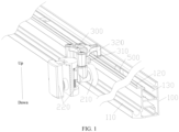
- a slide rail assembly includes: a slide rail 100 provided with a sliding chute 110 having an upwardly opened notch and a stopper 120; a pulley device including a pulley 210 and a mounting seat 220, the pulley 210 being uprightly disposed and rotatably mounted on the mounting seat 220, and the pulley 210 being hung over the sliding chute 110 and being movable along a length direction of the sliding chute 110; and a limiter 300 fixed on the mounting seat 220, the limiter 300 being provided with a limiting portion 310 which is located below the stopper 120.
- the stopper 120 prevents the pulley 210 from upwardly moving out of the sliding chute 110 by limiting the upward movement of the limiting portion 310.
- the notch of the sliding chute 110 in the slide rail 100 faces upward, the pulley 210 of the pulley device is hung over the sliding chute 110, and the limiter 300 is fixed on the mounting seat 220 of the pulley device.
- the limiting portion 310 of the limiter 300 is located below the stopper 120 of the slide rail 100, and the stopper 120 limits the upward movement of the limiting portion 310, so that the pulley 210 is prevented from upwardly moving out of the sliding chute 110 from the notch of the sliding chute 110.
- the pulley 210 may not upwardly move out of the sliding chute 110 when moving along the sliding chute 110. Therefore, the slide rail assembly is applied to a shower room without a problem that a glass door falls and breaks, and the shower room is safer when in use.
- the slide rail assembly further includes a buffer 400 disposed on the limiting portion 310 to prevent the limiting portion 310 from colliding with the stopper 120 rigidly, so that the limiter 300 and the slide rail 100 are less likely to be damaged during use.
- the buffer 400 may be disposed as a buffer sleeve, and the buffer sleeve is sleeved on the limiting portion 310, so that the buffer sleeve is not easy to fall off during use.
- the slide rail 100 is further provided with a guiding and limiting groove 130.
- the guiding and limiting groove 130 is parallel to the sliding chute 110 and has the same length as the sliding chute 110.
- the limiter 300 is further provided with a guiding and limiting portion 320 which extends into the guiding and limiting groove 130 and is movable along the guiding and limiting groove 130.
- a groove wall of the guiding and limiting groove 130 limits the guiding and limiting portion 320 to move along a width direction of the sliding chute 110, so as to prevent the pulley 210 from swinging in the width direction of the sliding chute 110, and ensure that the limiting portion 310 is always located just below the stopper 120, so that the pulley 210 is less likely to move out of the sliding chute 110 from the notch of the sliding chute 110, and the shake amount of the pulley device during use is also smaller.
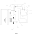
- the slide rail assembly further includes two sets of dampers 500, which are fixed at two ends of the guiding and limiting groove 130 (understood with reference to FIGS. 1 and 2 ), respectively, and are used to slow down the guiding and limiting portion 320, that is, to slow down the pulley device when the guiding and limiting portion 320 moves to the end of the traveling distance (that is, each end of the guiding and limiting groove 130).
- the two sets of dampers 500 may be two dampers 500 or four dampers 500, which can be reasonably selected according to the number of movable glass doors.
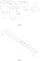
- each damper 500 includes: a body 510 fixed at the end of the guiding and limiting groove 130, the body 510 being provided with a sliding groove 511; and a damping slider 520 disposed in the sliding groove 511 and movable along the sliding groove 511.
- the sliding groove 511 is parallel to the slide rail 100, and the length of the sliding groove 511 is far less than that of the slide rail 100.
- the body 510 can be fixed on a bottom wall of the guiding and limiting groove 130 by screws or fastening screws after the determination of its position at the end of the guiding and limiting groove 130 as required.
- the guiding and limiting groove 130 may be disposed as a T-shaped groove.
- the damping slider 520 is provided with a mating notch 521.
- the guiding and limiting portion 320 may enter the sliding groove 511 and then be snapped into the mating notch 521.
- the guiding and limiting portion 320 may move out of the mating notch 521 and then slide out of the sliding groove 511, thus separating from the damper 500 and realizing quick door opening.
- the guiding and limiting groove 130 is located at the top of the slide rail 100, with the notch facing upwards, and the notch of the sliding groove 511 also faces upwards.
- the sliding chute 110 and the stopper 120 are located at the same side of the slide rail 100, and the stopper 120 is located above the sliding chute 110.
- the stopper 310 and the guiding and limiting portion 320 are both located at the same side of the limiter 300, and the limiting portion 310 is located below the guiding and limiting portion 320.
- Such structure is applied for a shower room to make the operation more simple and convenient for operators.
- the limiting portion 310 is a horizontally arranged limiting plate, which is located just below the stopper 120.
- the distance between the limiting plate and the stopper 120 is a, the depth of the pulley 210 sinking into the sliding chute 110 is b, wherein a is less than b.
- the length of the stopper 120 is the same as that of the sliding chute 110. Therefore, the pulley 210 may not upwardly move out of the sliding chute 110.
- the guiding and limiting portion 320 includes a horizontally arranged connecting arm and a vertically disposed guiding and limiting arm.
- An upper end of the guiding and limiting arm is connected to a side surface of the limiter 300 by the connecting arm, and a lower end of the guiding and limiting arm extends downward into the guiding and limiting groove 130.
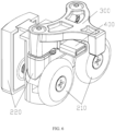
- the mounting seat 220 includes: a pulley seat 230, two sets of pulleys 210 spaced horizontally being both rotatably mounted on a side of the pulley seat 230 facing the slide rail 100; a door body connecting seat 240.
- the pulley seat 230 is located between the door body connecting seat 240 and the slide rail 100.
- the pulley seat 230 can be mounted at a side of the door body connecting seat 240 in a horizontally swinging manner by bolts, so that the angles of the two sets of pulleys 210 can be adjusted in a horizontal direction, which can better ensure the smooth movement of the two sets of pulleys 210 along the slide rail 100.
- the door body connecting seat 240 is used to be assembled with a door body to form a sliding door structure.
- the door body may be disposed as a glass door.
- the pulley device is firstly hung over the slide rail 100, then the limiter 300 is mounted on the slide rail 100, and finally, the limiter 300 and the pulley seat 230 are fixed together by screws.
- the door body connecting seat 240 includes a first connecting seat 241, a second connecting seat 242, a spacer 243 and a decorative cover 244 and the like. After the first connecting seat 241, the second connecting seat 242 and the spacer 243 are mounted on the glass door, a screw is screwed on the first connecting seat 241 after passing through the second connecting seat 242, the spacer 243 and the glass door, and finally the decorative cover 244 is mounted on the second connecting seat 242.
- a shower room (not shown in the figures) provided by the present invention includes a door body and the slide rail assembly of any of aforementioned embodiments, and the mounting seat is assembled with the door body.
- the door body is provided as a glass door.
- the notch of the sliding chute in the slide rail faces upward
- the pulley of the pulley device is hung over the sliding chute
- the limiting portion of the limiter is located below the stopper of the slide rail
- the stopper limits the upward movement of the limiting portion, so that the pulley is prevented from upwardly moving out of the sliding chute from the notch of the sliding chute, and the pulley may not upwardly move out of the sliding chute when moving along the sliding chute. Therefore, the slide rail assembly is applied to the shower room without a problem that the glass door falls and breaks, and the shower room is safer when in use.
- orientation or position relationships indicated by the terms “upper”, “lower”, “one side”, “other side”, “one end”, “other end”, “side”, “relative”, “four corners”, “periphery” and “square structure” and the like are based on the orientation or position relationships shown in the drawings, which are only for convenience of describing the present disclosure and simplifying the description, rather than indicating or implying that the structure referred has the specific orientation, or is constructed and operated in the specific orientation, and thus cannot be interpreted as a limitation on the present disclosure.
- connection In the description of the embodiments of the present disclosure, unless otherwise explicitly specified and limited, the terms “connection”, “direct connection”, “indirect connection”, “fixed connection”, “mounting” and “assembly” should be understood in a broad sense. For example, they may be fixed connection, detachable connection or integrated connection.
- mounting The terms “mounting”, “connection” and “fixed connection” may be direct connection, or indirect connection through an intermediary, or may be an internal communication between two elements.
Landscapes
- Engineering & Computer Science (AREA)
- Mechanical Engineering (AREA)
- Wing Frames And Configurations (AREA)
- Support Devices For Sliding Doors (AREA)
Applications Claiming Priority (1)
| Application Number | Priority Date | Filing Date | Title |
|---|---|---|---|
| CN202111320522.6A CN113969716B (zh) | 2021-11-09 | 2021-11-09 | 一种滑轨组件和淋浴房 |
Publications (3)
| Publication Number | Publication Date |
|---|---|
| EP4177429A1 EP4177429A1 (en) | 2023-05-10 |
| EP4177429B1 true EP4177429B1 (en) | 2024-03-06 |
| EP4177429C0 EP4177429C0 (en) | 2024-03-06 |
Family
ID=79589488
Family Applications (1)
| Application Number | Title | Priority Date | Filing Date |
|---|---|---|---|
| EP22164280.4A Active EP4177429B1 (en) | 2021-11-09 | 2022-03-25 | Slide rail assembly and shower room |
Country Status (4)
| Country | Link |
|---|---|
| EP (1) | EP4177429B1 (pl) |
| CN (1) | CN113969716B (pl) |
| ES (1) | ES2975785T3 (pl) |
| PL (1) | PL4177429T3 (pl) |
Families Citing this family (1)
| Publication number | Priority date | Publication date | Assignee | Title |
|---|---|---|---|---|
| CN113969716B (zh) * | 2021-11-09 | 2024-11-08 | 福建西河卫浴科技有限公司 | 一种滑轨组件和淋浴房 |
Family Cites Families (13)
| Publication number | Priority date | Publication date | Assignee | Title |
|---|---|---|---|---|
| DE202009002713U1 (de) * | 2009-02-25 | 2010-07-15 | Hettich-Heinze Gmbh & Co. Kg | Gleitbeschlag |
| CN201486324U (zh) * | 2009-06-29 | 2010-05-26 | 王风 | 一种淋浴房导轨 |
| JP4902772B2 (ja) * | 2010-06-15 | 2012-03-21 | 山金工業株式会社 | 脱輪防止機能を有する引戸用戸車装置及びこれを用いる引戸装置 |
| KR101068926B1 (ko) * | 2011-06-17 | 2011-10-04 | (주)메탈프린스 | 붙박이장의 내측도어용 롤러 이탈 방지장치 |
| CN203476042U (zh) * | 2013-07-30 | 2014-03-12 | 佛山市理想卫浴有限公司 | 具有自动关门功能的淋浴门组件 |
| DE102014103851B4 (de) * | 2014-03-20 | 2016-11-10 | Rennerich Gmbh | Rollenführung |
| CN207714976U (zh) * | 2017-12-29 | 2018-08-10 | 中山市瑞莎卫浴科技有限公司 | 一种淋浴房防脱轨结构 |
| CN208184496U (zh) * | 2018-03-27 | 2018-12-04 | 广东图特家居科技股份有限公司 | 滑轮导轨系统及衣柜 |
| CN110344696B (zh) * | 2019-07-05 | 2025-02-11 | 福建省德牧卫浴科技有限公司 | 一种滑轮组件 |
| CN211950062U (zh) * | 2019-12-16 | 2020-11-17 | 中山市福瑞卫浴设备有限公司 | 一种用于淋浴房的防脱跳机构 |
| CN213869418U (zh) * | 2020-10-10 | 2021-08-03 | 佛山市凯庭卫浴科技有限公司 | 一种防脱轨的淋浴房玻璃移门结构 |
| CN217028524U (zh) * | 2021-11-09 | 2022-07-22 | 福建西河卫浴科技有限公司 | 一种滑轨组件和淋浴房 |
| CN113969716B (zh) * | 2021-11-09 | 2024-11-08 | 福建西河卫浴科技有限公司 | 一种滑轨组件和淋浴房 |
-
2021
- 2021-11-09 CN CN202111320522.6A patent/CN113969716B/zh active Active
-
2022
- 2022-03-25 EP EP22164280.4A patent/EP4177429B1/en active Active
- 2022-03-25 PL PL22164280.4T patent/PL4177429T3/pl unknown
- 2022-03-25 ES ES22164280T patent/ES2975785T3/es active Active
Also Published As
| Publication number | Publication date |
|---|---|
| CN113969716A (zh) | 2022-01-25 |
| ES2975785T3 (es) | 2024-07-15 |
| CN113969716B (zh) | 2024-11-08 |
| EP4177429A1 (en) | 2023-05-10 |
| EP4177429C0 (en) | 2024-03-06 |
| PL4177429T3 (pl) | 2024-06-10 |
Similar Documents
| Publication | Publication Date | Title |
|---|---|---|
| EP2330270A2 (en) | Side hung and bottom hung double-opening window, structure, and control device thereof | |
| EP4177429B1 (en) | Slide rail assembly and shower room | |
| US20170130512A1 (en) | Sliding window arrangement | |
| US5033235A (en) | Window jamb liner with concealed spring pocket and friction slide | |
| US3328105A (en) | Self-closing, sliding door assembly | |
| CN217028524U (zh) | 一种滑轨组件和淋浴房 | |
| KR101834972B1 (ko) | 양방향 댐퍼 및 스프링부에 의하여 개폐속도조절 및 자동이송이 가능한 폴딩도어 | |
| KR101825080B1 (ko) | 걸림턱에 의하여 개폐속도조절 및 자동이송이 가능한 폴딩도어 | |
| JPS6210388A (ja) | 壁掛け家具用の扉開閉装置 | |
| CN205445252U (zh) | 家具阻尼器 | |
| AU2016100639A4 (en) | A Sliding Window Arrangement | |
| JP3532168B2 (ja) | スライドパネル式収納家具 | |
| KR101752693B1 (ko) | 속도조절용 다중 슬라이드 도어 | |
| CN223536180U (zh) | 一种高适用性带保险的限位通风器 | |
| KR20070066831A (ko) | 시스템창호 개폐장치 | |
| IE950578A1 (en) | Window structure | |
| EP0606956A1 (en) | Balance system and guide for up-and-over sectional door provided with counterweight | |
| CN213869498U (zh) | 一种升降窗扇的高低平衡调节结构 | |
| CN218563369U (zh) | 一种新型吊体 | |
| CN211923900U (zh) | 一种趟门缓冲器的防跳结构 | |
| TW201314007A (zh) | 推開窗之定位結構 | |
| CN211712413U (zh) | 一种简易安全触板装置 | |
| KR102848840B1 (ko) | 슬라이딩 댐퍼 | |
| JPH0750539Y2 (ja) | すべり出し窓のスイング装置 | |
| CN211058532U (zh) | 一种缓冲门吸 |
Legal Events
| Date | Code | Title | Description |
|---|---|---|---|
| PUAI | Public reference made under article 153(3) epc to a published international application that has entered the european phase |
Free format text: ORIGINAL CODE: 0009012 |
|
| STAA | Information on the status of an ep patent application or granted ep patent |
Free format text: STATUS: REQUEST FOR EXAMINATION WAS MADE |
|
| 17P | Request for examination filed |
Effective date: 20220325 |
|
| AK | Designated contracting states |
Kind code of ref document: A1 Designated state(s): AL AT BE BG CH CY CZ DE DK EE ES FI FR GB GR HR HU IE IS IT LI LT LU LV MC MK MT NL NO PL PT RO RS SE SI SK SM TR |
|
| GRAP | Despatch of communication of intention to grant a patent |
Free format text: ORIGINAL CODE: EPIDOSNIGR1 |
|
| STAA | Information on the status of an ep patent application or granted ep patent |
Free format text: STATUS: GRANT OF PATENT IS INTENDED |
|
| RIC1 | Information provided on ipc code assigned before grant |
Ipc: E05F 5/00 20170101ALI20230920BHEP Ipc: A47K 3/34 20060101ALI20230920BHEP Ipc: E05D 15/06 20060101AFI20230920BHEP |
|
| INTG | Intention to grant announced |
Effective date: 20231017 |
|
| GRAS | Grant fee paid |
Free format text: ORIGINAL CODE: EPIDOSNIGR3 |
|
| GRAA | (expected) grant |
Free format text: ORIGINAL CODE: 0009210 |
|
| STAA | Information on the status of an ep patent application or granted ep patent |
Free format text: STATUS: THE PATENT HAS BEEN GRANTED |
|
| AK | Designated contracting states |
Kind code of ref document: B1 Designated state(s): AL AT BE BG CH CY CZ DE DK EE ES FI FR GB GR HR HU IE IS IT LI LT LU LV MC MK MT NL NO PL PT RO RS SE SI SK SM TR |
|
| REG | Reference to a national code |
Ref country code: CH Ref legal event code: EP |
|
| REG | Reference to a national code |
Ref country code: DE Ref legal event code: R096 Ref document number: 602022002201 Country of ref document: DE |
|
| REG | Reference to a national code |
Ref country code: IE Ref legal event code: FG4D |
|
| U01 | Request for unitary effect filed |
Effective date: 20240326 |
|
| U07 | Unitary effect registered |
Designated state(s): AT BE BG DE DK EE FI FR IT LT LU LV MT NL PT SE SI Effective date: 20240405 |
|
| U20 | Renewal fee for the european patent with unitary effect paid |
Year of fee payment: 3 Effective date: 20240416 |
|
| PG25 | Lapsed in a contracting state [announced via postgrant information from national office to epo] |
Ref country code: GR Free format text: LAPSE BECAUSE OF FAILURE TO SUBMIT A TRANSLATION OF THE DESCRIPTION OR TO PAY THE FEE WITHIN THE PRESCRIBED TIME-LIMIT Effective date: 20240607 |
|
| REG | Reference to a national code |
Ref country code: ES Ref legal event code: FG2A Ref document number: 2975785 Country of ref document: ES Kind code of ref document: T3 Effective date: 20240715 |
|
| PG25 | Lapsed in a contracting state [announced via postgrant information from national office to epo] |
Ref country code: HR Free format text: LAPSE BECAUSE OF FAILURE TO SUBMIT A TRANSLATION OF THE DESCRIPTION OR TO PAY THE FEE WITHIN THE PRESCRIBED TIME-LIMIT Effective date: 20240306 Ref country code: RS Free format text: LAPSE BECAUSE OF FAILURE TO SUBMIT A TRANSLATION OF THE DESCRIPTION OR TO PAY THE FEE WITHIN THE PRESCRIBED TIME-LIMIT Effective date: 20240606 |
|
| PG25 | Lapsed in a contracting state [announced via postgrant information from national office to epo] |
Ref country code: RS Free format text: LAPSE BECAUSE OF FAILURE TO SUBMIT A TRANSLATION OF THE DESCRIPTION OR TO PAY THE FEE WITHIN THE PRESCRIBED TIME-LIMIT Effective date: 20240606 Ref country code: NO Free format text: LAPSE BECAUSE OF FAILURE TO SUBMIT A TRANSLATION OF THE DESCRIPTION OR TO PAY THE FEE WITHIN THE PRESCRIBED TIME-LIMIT Effective date: 20240606 Ref country code: HR Free format text: LAPSE BECAUSE OF FAILURE TO SUBMIT A TRANSLATION OF THE DESCRIPTION OR TO PAY THE FEE WITHIN THE PRESCRIBED TIME-LIMIT Effective date: 20240306 Ref country code: GR Free format text: LAPSE BECAUSE OF FAILURE TO SUBMIT A TRANSLATION OF THE DESCRIPTION OR TO PAY THE FEE WITHIN THE PRESCRIBED TIME-LIMIT Effective date: 20240607 |
|
| PG25 | Lapsed in a contracting state [announced via postgrant information from national office to epo] |
Ref country code: IS Free format text: LAPSE BECAUSE OF FAILURE TO SUBMIT A TRANSLATION OF THE DESCRIPTION OR TO PAY THE FEE WITHIN THE PRESCRIBED TIME-LIMIT Effective date: 20240706 |
|
| PG25 | Lapsed in a contracting state [announced via postgrant information from national office to epo] |
Ref country code: SM Free format text: LAPSE BECAUSE OF FAILURE TO SUBMIT A TRANSLATION OF THE DESCRIPTION OR TO PAY THE FEE WITHIN THE PRESCRIBED TIME-LIMIT Effective date: 20240306 |
|
| PG25 | Lapsed in a contracting state [announced via postgrant information from national office to epo] |
Ref country code: CZ Free format text: LAPSE BECAUSE OF FAILURE TO SUBMIT A TRANSLATION OF THE DESCRIPTION OR TO PAY THE FEE WITHIN THE PRESCRIBED TIME-LIMIT Effective date: 20240306 |
|
| PG25 | Lapsed in a contracting state [announced via postgrant information from national office to epo] |
Ref country code: SK Free format text: LAPSE BECAUSE OF FAILURE TO SUBMIT A TRANSLATION OF THE DESCRIPTION OR TO PAY THE FEE WITHIN THE PRESCRIBED TIME-LIMIT Effective date: 20240306 |
|
| PG25 | Lapsed in a contracting state [announced via postgrant information from national office to epo] |
Ref country code: SM Free format text: LAPSE BECAUSE OF FAILURE TO SUBMIT A TRANSLATION OF THE DESCRIPTION OR TO PAY THE FEE WITHIN THE PRESCRIBED TIME-LIMIT Effective date: 20240306 Ref country code: SK Free format text: LAPSE BECAUSE OF FAILURE TO SUBMIT A TRANSLATION OF THE DESCRIPTION OR TO PAY THE FEE WITHIN THE PRESCRIBED TIME-LIMIT Effective date: 20240306 Ref country code: RO Free format text: LAPSE BECAUSE OF FAILURE TO SUBMIT A TRANSLATION OF THE DESCRIPTION OR TO PAY THE FEE WITHIN THE PRESCRIBED TIME-LIMIT Effective date: 20240306 Ref country code: IS Free format text: LAPSE BECAUSE OF FAILURE TO SUBMIT A TRANSLATION OF THE DESCRIPTION OR TO PAY THE FEE WITHIN THE PRESCRIBED TIME-LIMIT Effective date: 20240706 Ref country code: CZ Free format text: LAPSE BECAUSE OF FAILURE TO SUBMIT A TRANSLATION OF THE DESCRIPTION OR TO PAY THE FEE WITHIN THE PRESCRIBED TIME-LIMIT Effective date: 20240306 |
|
| REG | Reference to a national code |
Ref country code: DE Ref legal event code: R097 Ref document number: 602022002201 Country of ref document: DE |
|
| PG25 | Lapsed in a contracting state [announced via postgrant information from national office to epo] |
Ref country code: MC Free format text: LAPSE BECAUSE OF FAILURE TO SUBMIT A TRANSLATION OF THE DESCRIPTION OR TO PAY THE FEE WITHIN THE PRESCRIBED TIME-LIMIT Effective date: 20240306 |
|
| PLBE | No opposition filed within time limit |
Free format text: ORIGINAL CODE: 0009261 |
|
| STAA | Information on the status of an ep patent application or granted ep patent |
Free format text: STATUS: NO OPPOSITION FILED WITHIN TIME LIMIT |
|
| PG25 | Lapsed in a contracting state [announced via postgrant information from national office to epo] |
Ref country code: IE Free format text: LAPSE BECAUSE OF NON-PAYMENT OF DUE FEES Effective date: 20240325 |
|
| PG25 | Lapsed in a contracting state [announced via postgrant information from national office to epo] |
Ref country code: MC Free format text: LAPSE BECAUSE OF FAILURE TO SUBMIT A TRANSLATION OF THE DESCRIPTION OR TO PAY THE FEE WITHIN THE PRESCRIBED TIME-LIMIT Effective date: 20240306 Ref country code: IE Free format text: LAPSE BECAUSE OF NON-PAYMENT OF DUE FEES Effective date: 20240325 |
|
| 26N | No opposition filed |
Effective date: 20241209 |
|
| PGFP | Annual fee paid to national office [announced via postgrant information from national office to epo] |
Ref country code: PL Payment date: 20250225 Year of fee payment: 4 |
|
| U20 | Renewal fee for the european patent with unitary effect paid |
Year of fee payment: 4 Effective date: 20250331 |
|
| PGFP | Annual fee paid to national office [announced via postgrant information from national office to epo] |
Ref country code: ES Payment date: 20250407 Year of fee payment: 4 |
|
| PG25 | Lapsed in a contracting state [announced via postgrant information from national office to epo] |
Ref country code: CY Free format text: LAPSE BECAUSE OF FAILURE TO SUBMIT A TRANSLATION OF THE DESCRIPTION OR TO PAY THE FEE WITHIN THE PRESCRIBED TIME-LIMIT; INVALID AB INITIO Effective date: 20220325 |
|
| REG | Reference to a national code |
Ref country code: CH Ref legal event code: H13 Free format text: ST27 STATUS EVENT CODE: U-0-0-H10-H13 (AS PROVIDED BY THE NATIONAL OFFICE) Effective date: 20251023 |
|
| PG25 | Lapsed in a contracting state [announced via postgrant information from national office to epo] |
Ref country code: TR Free format text: LAPSE BECAUSE OF FAILURE TO SUBMIT A TRANSLATION OF THE DESCRIPTION OR TO PAY THE FEE WITHIN THE PRESCRIBED TIME-LIMIT Effective date: 20240306 |
|
| PG25 | Lapsed in a contracting state [announced via postgrant information from national office to epo] |
Ref country code: CH Free format text: LAPSE BECAUSE OF NON-PAYMENT OF DUE FEES Effective date: 20250331 |