EP4177223A1 - Method of administering coagulant - Google Patents
Method of administering coagulant Download PDFInfo
- Publication number
- EP4177223A1 EP4177223A1 EP21838112.7A EP21838112A EP4177223A1 EP 4177223 A1 EP4177223 A1 EP 4177223A1 EP 21838112 A EP21838112 A EP 21838112A EP 4177223 A1 EP4177223 A1 EP 4177223A1
- Authority
- EP
- European Patent Office
- Prior art keywords
- filtration
- membrane
- coagulant
- water
- tank
- Prior art date
- Legal status (The legal status is an assumption and is not a legal conclusion. Google has not performed a legal analysis and makes no representation as to the accuracy of the status listed.)
- Pending
Links
- 239000000701 coagulant Substances 0.000 title claims abstract description 279
- 238000000034 method Methods 0.000 title claims abstract description 70
- 238000001914 filtration Methods 0.000 claims abstract description 355
- XLYOFNOQVPJJNP-UHFFFAOYSA-N water Substances O XLYOFNOQVPJJNP-UHFFFAOYSA-N 0.000 claims abstract description 345
- 239000012528 membrane Substances 0.000 claims abstract description 312
- 238000012544 monitoring process Methods 0.000 claims description 45
- 238000000605 extraction Methods 0.000 claims description 24
- 239000012466 permeate Substances 0.000 claims description 10
- 239000002351 wastewater Substances 0.000 description 128
- 206010002660 Anoxia Diseases 0.000 description 34
- 241000976983 Anoxia Species 0.000 description 34
- 206010021143 Hypoxia Diseases 0.000 description 34
- 230000007953 anoxia Effects 0.000 description 34
- 230000003247 decreasing effect Effects 0.000 description 30
- 230000004907 flux Effects 0.000 description 27
- 238000003809 water extraction Methods 0.000 description 21
- 230000035699 permeability Effects 0.000 description 15
- 239000010802 sludge Substances 0.000 description 12
- 238000013461 design Methods 0.000 description 8
- 230000000694 effects Effects 0.000 description 8
- 238000000926 separation method Methods 0.000 description 7
- 238000005406 washing Methods 0.000 description 7
- 238000010586 diagram Methods 0.000 description 5
- 244000144992 flock Species 0.000 description 4
- 230000014509 gene expression Effects 0.000 description 4
- 101150049281 PRM1 gene Proteins 0.000 description 3
- 238000009792 diffusion process Methods 0.000 description 3
- GRYLNZFGIOXLOG-UHFFFAOYSA-N Nitric acid Chemical compound O[N+]([O-])=O GRYLNZFGIOXLOG-UHFFFAOYSA-N 0.000 description 2
- 101150106023 PRM2 gene Proteins 0.000 description 2
- 230000007423 decrease Effects 0.000 description 2
- 229910017604 nitric acid Inorganic materials 0.000 description 2
- 238000012545 processing Methods 0.000 description 2
- 238000011144 upstream manufacturing Methods 0.000 description 2
- IJGRMHOSHXDMSA-UHFFFAOYSA-N Atomic nitrogen Chemical compound N#N IJGRMHOSHXDMSA-UHFFFAOYSA-N 0.000 description 1
- XKMRRTOUMJRJIA-UHFFFAOYSA-N ammonia nh3 Chemical compound N.N XKMRRTOUMJRJIA-UHFFFAOYSA-N 0.000 description 1
- 230000000903 blocking effect Effects 0.000 description 1
- 229910001873 dinitrogen Inorganic materials 0.000 description 1
- 239000012510 hollow fiber Substances 0.000 description 1
- 239000007788 liquid Substances 0.000 description 1
- 238000012986 modification Methods 0.000 description 1
- 230000004048 modification Effects 0.000 description 1
- 239000005416 organic matter Substances 0.000 description 1
- 230000002085 persistent effect Effects 0.000 description 1
- 239000000126 substance Substances 0.000 description 1
- 238000003466 welding Methods 0.000 description 1
Images



Classifications
-
- C—CHEMISTRY; METALLURGY
- C02—TREATMENT OF WATER, WASTE WATER, SEWAGE, OR SLUDGE
- C02F—TREATMENT OF WATER, WASTE WATER, SEWAGE, OR SLUDGE
- C02F1/00—Treatment of water, waste water, or sewage
- C02F1/44—Treatment of water, waste water, or sewage by dialysis, osmosis or reverse osmosis
-
- B—PERFORMING OPERATIONS; TRANSPORTING
- B01—PHYSICAL OR CHEMICAL PROCESSES OR APPARATUS IN GENERAL
- B01D—SEPARATION
- B01D61/00—Processes of separation using semi-permeable membranes, e.g. dialysis, osmosis or ultrafiltration; Apparatus, accessories or auxiliary operations specially adapted therefor
- B01D61/14—Ultrafiltration; Microfiltration
- B01D61/16—Feed pretreatment
-
- B—PERFORMING OPERATIONS; TRANSPORTING
- B01—PHYSICAL OR CHEMICAL PROCESSES OR APPARATUS IN GENERAL
- B01D—SEPARATION
- B01D61/00—Processes of separation using semi-permeable membranes, e.g. dialysis, osmosis or ultrafiltration; Apparatus, accessories or auxiliary operations specially adapted therefor
- B01D61/14—Ultrafiltration; Microfiltration
- B01D61/22—Controlling or regulating
-
- B—PERFORMING OPERATIONS; TRANSPORTING
- B01—PHYSICAL OR CHEMICAL PROCESSES OR APPARATUS IN GENERAL
- B01D—SEPARATION
- B01D65/00—Accessories or auxiliary operations, in general, for separation processes or apparatus using semi-permeable membranes
- B01D65/08—Prevention of membrane fouling or of concentration polarisation
-
- C—CHEMISTRY; METALLURGY
- C02—TREATMENT OF WATER, WASTE WATER, SEWAGE, OR SLUDGE
- C02F—TREATMENT OF WATER, WASTE WATER, SEWAGE, OR SLUDGE
- C02F1/00—Treatment of water, waste water, or sewage
- C02F1/52—Treatment of water, waste water, or sewage by flocculation or precipitation of suspended impurities
- C02F1/5209—Regulation methods for flocculation or precipitation
-
- B—PERFORMING OPERATIONS; TRANSPORTING
- B01—PHYSICAL OR CHEMICAL PROCESSES OR APPARATUS IN GENERAL
- B01D—SEPARATION
- B01D2311/00—Details relating to membrane separation process operations and control
- B01D2311/04—Specific process operations in the feed stream; Feed pretreatment
-
- B—PERFORMING OPERATIONS; TRANSPORTING
- B01—PHYSICAL OR CHEMICAL PROCESSES OR APPARATUS IN GENERAL
- B01D—SEPARATION
- B01D2311/00—Details relating to membrane separation process operations and control
- B01D2311/12—Addition of chemical agents
-
- B—PERFORMING OPERATIONS; TRANSPORTING
- B01—PHYSICAL OR CHEMICAL PROCESSES OR APPARATUS IN GENERAL
- B01D—SEPARATION
- B01D2311/00—Details relating to membrane separation process operations and control
- B01D2311/14—Pressure control
-
- B—PERFORMING OPERATIONS; TRANSPORTING
- B01—PHYSICAL OR CHEMICAL PROCESSES OR APPARATUS IN GENERAL
- B01D—SEPARATION
- B01D2311/00—Details relating to membrane separation process operations and control
- B01D2311/16—Flow or flux control
-
- B—PERFORMING OPERATIONS; TRANSPORTING
- B01—PHYSICAL OR CHEMICAL PROCESSES OR APPARATUS IN GENERAL
- B01D—SEPARATION
- B01D2311/00—Details relating to membrane separation process operations and control
- B01D2311/26—Further operations combined with membrane separation processes
- B01D2311/2642—Aggregation, sedimentation, flocculation, precipitation or coagulation
-
- B—PERFORMING OPERATIONS; TRANSPORTING
- B01—PHYSICAL OR CHEMICAL PROCESSES OR APPARATUS IN GENERAL
- B01D—SEPARATION
- B01D2315/00—Details relating to the membrane module operation
- B01D2315/06—Submerged-type; Immersion type
-
- C—CHEMISTRY; METALLURGY
- C02—TREATMENT OF WATER, WASTE WATER, SEWAGE, OR SLUDGE
- C02F—TREATMENT OF WATER, WASTE WATER, SEWAGE, OR SLUDGE
- C02F2209/00—Controlling or monitoring parameters in water treatment
- C02F2209/03—Pressure
-
- C—CHEMISTRY; METALLURGY
- C02—TREATMENT OF WATER, WASTE WATER, SEWAGE, OR SLUDGE
- C02F—TREATMENT OF WATER, WASTE WATER, SEWAGE, OR SLUDGE
- C02F2209/00—Controlling or monitoring parameters in water treatment
- C02F2209/42—Liquid level
-
- C—CHEMISTRY; METALLURGY
- C02—TREATMENT OF WATER, WASTE WATER, SEWAGE, OR SLUDGE
- C02F—TREATMENT OF WATER, WASTE WATER, SEWAGE, OR SLUDGE
- C02F2209/00—Controlling or monitoring parameters in water treatment
- C02F2209/44—Time
-
- C—CHEMISTRY; METALLURGY
- C02—TREATMENT OF WATER, WASTE WATER, SEWAGE, OR SLUDGE
- C02F—TREATMENT OF WATER, WASTE WATER, SEWAGE, OR SLUDGE
- C02F2301/00—General aspects of water treatment
- C02F2301/08—Multistage treatments, e.g. repetition of the same process step under different conditions
-
- C—CHEMISTRY; METALLURGY
- C02—TREATMENT OF WATER, WASTE WATER, SEWAGE, OR SLUDGE
- C02F—TREATMENT OF WATER, WASTE WATER, SEWAGE, OR SLUDGE
- C02F2303/00—Specific treatment goals
- C02F2303/16—Regeneration of sorbents, filters
-
- C—CHEMISTRY; METALLURGY
- C02—TREATMENT OF WATER, WASTE WATER, SEWAGE, OR SLUDGE
- C02F—TREATMENT OF WATER, WASTE WATER, SEWAGE, OR SLUDGE
- C02F3/00—Biological treatment of water, waste water, or sewage
- C02F3/30—Aerobic and anaerobic processes
- C02F3/302—Nitrification and denitrification treatment
-
- Y—GENERAL TAGGING OF NEW TECHNOLOGICAL DEVELOPMENTS; GENERAL TAGGING OF CROSS-SECTIONAL TECHNOLOGIES SPANNING OVER SEVERAL SECTIONS OF THE IPC; TECHNICAL SUBJECTS COVERED BY FORMER USPC CROSS-REFERENCE ART COLLECTIONS [XRACs] AND DIGESTS
- Y02—TECHNOLOGIES OR APPLICATIONS FOR MITIGATION OR ADAPTATION AGAINST CLIMATE CHANGE
- Y02W—CLIMATE CHANGE MITIGATION TECHNOLOGIES RELATED TO WASTEWATER TREATMENT OR WASTE MANAGEMENT
- Y02W10/00—Technologies for wastewater treatment
- Y02W10/10—Biological treatment of water, waste water, or sewage
Definitions
- the present invention relates to a method of administering a coagulant to be administered in water to be filtered at the time of performing water treatment by filtering the water to be filtered with a filter membrane.
- the membrane separation activated sludge method is known.
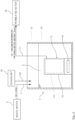
- a processing device 103 is used that provides a membrane separator 102 in a filtration tank 101.
- the membrane separator 102 includes a plurality of membrane elements 105 arranged in a casing 104, and an air diffuser 106 that diffuses air from below the membrane elements 105.
- Each of the membrane elements 105 is formed by welding a filter membrane on both front and rear surfaces of a filter plate.
- the permeated water (treated water) that permeates from the upstream side to the downstream side through a filter membrane is sent out to the outside of the filtration tank 101 through a permeated water extraction flow path 107.
- the water to be filtered 108 such as waste water, is supplied from a supply flow path 109 into the filtration tank 101, and a coagulant 110 is administered from a coagulant administration flow path 111 to the water to be filtered 108 in the filtration tank 101.
- the coagulant 110 sticks to the sludge surface, and adsorbs organic matters, such as persistent substances. Therefore, membrane blocking of the filter membranes of the membrane elements 105 can be prevented.
- An object of the present invention is to provide a method of administering a coagulant that can start administration of the coagulant at an optimum timing, and can stop the administration of the coagulant at an optimum timing after starting the administration of the coagulant.
- a method of administering a coagulant in water treatment of the present invention defines one treatment cycle as including a filtration step for using a filter membrane to filter water to be treated in a filtration tank, and a filtration stopping step for stopping filtration, and
- the larger the membrane load index the larger the amount of foulant (soluble organic matters, etc.) contained in the water to be treated.
- the permeation ratio resistance at the time when the foulant adheres to the filter membrane surfaces is increased. Therefore, the permeation resistance at the time of permeating the filter membranes is increased, and the load applied to the filter membranes is increased.
- the smaller the membrane load index the smaller the amount of the foulant contained in the water to be treated.
- the permeation ratio resistance at the time when the foulant adheres to the filter membrane surfaces is decreased. Therefore, the permeation resistance at the time of permeating the filter membranes is decreased, and the load applied to the filter membranes is decreased.
- the load applied to the filter membranes can be objectively evaluated based on the membrane load index at the time of the filtration step, and the administration of the coagulant is started by using this membrane load index as an index, the administration of the coagulant can be started at an optimum timing.
- a method of administering a coagulant in water treatment of the present invention defines one treatment cycle as including a filtration step for using a filter membrane to filter water to be treated in a filtration tank, and a filtration stopping step for stopping filtration, and
- a method of administering a coagulant in water treatment of the present invention defines one treatment cycle as including a filtration step for using a filter membrane to filter water to be treated in a filtration tank, and a filtration stopping step for stopping filtration, and repeats the treatment cycle to treat the water to be treated, wherein a membrane load index is defined as an amount of increase in transmembrane pressure per time in the filtration step,
- a method of administering a coagulant in water treatment of the present invention defines one treatment cycle as including a filtration step for using a filter membrane to filter water to be treated in a filtration tank, and a filtration stopping step for stopping filtration, and
- a method of administering a coagulant in water treatment of the present invention defines one treatment cycle as including a filtration step for using a filter membrane to filter water to be treated in a filtration tank, and a filtration stopping step for stopping filtration, and
- the larger the membrane load index the larger the amount of foulant (soluble organic matters, etc.) contained in the water to be treated.
- the permeation ratio resistance at the time when the foulant adheres to the filter membrane surfaces is increased. Therefore, the permeation resistance at the time of permeating the filter membranes is increased, and the load applied to the filter membranes is increased.
- the smaller the membrane load index the smaller the amount of foulant contained in the water to be treated.
- the permeation ratio resistance at the time when the foulant adheres to the filter membrane surfaces is decreased. Therefore, the permeation resistance at the time of permeating the filter membranes is decreased, and the load applied to the filter membranes is decreased.
- the foulant adhering to the film surfaces of the filter membranes can be removed, and the filter membranes can be washed.
- the larger the accumulated additional resistance the fewer the removal amount of the foulant removed from the filter membranes in the filtration stopping step of the treatment cycle (hereinafter referred to as the previous treatment cycle) immediately before the current treatment cycle, and the lower the washing effect of the filter membranes. Therefore, at the start of the filtration step of the current treatment cycle, the amount of the foulant remaining adhered to the filter membranes is large, and the permeability of the filter membranes is decreased.
- the smaller the accumulated additional resistance the larger the removal amount of the foulant removed from the filter membranes in the filtration stopping step of the previous treatment cycle, and the higher the washing effect of the filter membranes. Therefore, at the start of the filtration step of the current treatment cycle, the amount of the foulant remaining adhered to the filter membranes is decreased, and the permeability of the filter membranes is maintained.
- the washing effect of the filter membranes in the filtration stopping step of the previous treatment cycle can be objectively evaluated.
- the administration of the coagulant since the administration of the coagulant is started by using the membrane load index and the accumulated additional resistance as indexes, the administration of the coagulant can be started at an optimum timing.
- the membrane-filtered water amount per membrane area and per time becomes less than a third threshold value, the administration of the coagulant into the filtration tank is stopped.
- the administration of the coagulant is stopped by using the membrane-filtered water amount per membrane area and per time as the index, the administration of the coagulant can be stopped at an optimum timing after starting the administration of the coagulant.
- a method of administering a coagulant in water treatment of the present invention defines one treatment cycle as including a filtration step for using a filter membrane to filter water to be treated in a treatment tank including a filtration tank having the filter membrane, and a monitoring tank adjacent to the filtration tank, and a filtration stopping step for stopping filtration, and repeats the treatment cycle to treat the water to be treated, wherein, when an inflow of the water to be treated flowing into the treatment tank from outside exceeds an extraction amount of membrane-filtered water extracted from the filtration tank to the outside of the treatment tank, and thus a water level in the monitoring tank rises and becomes greater than or equal to a fourth threshold value, administration of the coagulant into the filtration tank is started.
- the membrane-filtered water amount (flux) per membrane area and per time is increased, so that the extraction amount of the membrane-filtered water extracted from the filtration tank to the outside of the treatment tank exceeds the inflow of the water to be treated flowing into the treatment tank from the outside.
- the administration of the coagulant can be started at an optimum timing.
- the method of administering the coagulant of the present invention it is preferable that, when the water to be treated overflowing from the filtration tank flows into the monitoring tank, and the water level in the monitoring tank becomes greater than or equal to the fourth threshold value, the administration of the coagulant into the filtration tank is started.
- the administration of the coagulant into the filtration tank is stopped.
- the membrane-filtered water amount (flux) per membrane area and per time is reduced.
- the administration of the coagulant can be stopped at an optimum timing after starting the administration of the coagulant.
- a method of administering a coagulant in water treatment of the present invention defines one treatment cycle as including a filtration step for using a filter membrane to filter water to be treated in a treatment tank including a filtration tank having the filter membrane, and a monitoring tank adjacent to the filtration tank, and a filtration stopping step for stopping filtration, and repeats the treatment cycle to treat the water to be treated, wherein, in the filtration step, when transmembrane pressure becomes greater than or equal to a sixth threshold value, administration of the coagulant into the filtration tank is started.
- the larger the transmembrane pressure the larger the load applied to the filter membrane. Therefore, the load applied to the filter membrane can be objectively evaluated based on the transmembrane pressure. Since the administration of the coagulant is started by using this transmembrane pressure as an index, the administration of the coagulant can be started at an optimum timing.
- the method of administering the coagulant of the present invention it is preferable to stop the administration of the coagulant when a predetermined time period elapses after starting the administration of the coagulant.
- the predetermined time period is a time period obtained by multiplying an actual residence time of the filtration tank in which the filter membrane is immersed by a value obtained by adding 1 to a circulation ratio
- the administration of the coagulant can be stopped at an optimum timing after starting the administration of the coagulant.
- a method of administering a coagulant in water treatment of the present invention defines one treatment cycle as including a filtration step for using a filter membrane to filter water to be treated in a filtration tank, and a filtration stopping step for stopping filtration, and repeats the treatment cycle to treat the water to be treated, wherein, in the filtration step, when a membrane-filtered water amount per membrane area and per time becomes greater than or equal to a seventh threshold value, administration of the coagulant into the filtration tank is started.
- the membrane-filtered water amount per membrane area and per time becomes less than an eighth threshold value lower than the seventh threshold value, the administration of the coagulant into the filtration tank is stopped.
- a method of administering a coagulant in water treatment of the present invention defines one treatment cycle as including a filtration step for using a filter membrane to filter water to be treated that is supplied to a treatment tank from outside, and a filtration stopping step for stopping filtration, and repeats the treatment cycle to treat the water to be treated, wherein, when an inflow of the water to be treated flowing into the treatment tank from the outside exceeds an extraction amount of membrane-filtered water that permeates the filter membrane and is extracted to the outside of the treatment tank, and thus a water level in the treatment tank rises and becomes greater than or equal to a ninth threshold value, administration of the coagulant into the treatment tank is started.
- the membrane-filtered water amount (flux) per membrane area and per time is increased, so that the extraction amount of the above-described membrane-filtered water exceeds the inflow of the above-described water to be treated.
- the administration of the coagulant can be started at an optimum timing.
- the method of administering the coagulant of the present invention it is preferable that, in the filtration step, when the water level of the water to be treated in the treatment tank becomes less than a tenth threshold value lower than the ninth threshold value, the administration of the coagulant into the treatment tank is stopped.
- the membrane-filtered water amount (flux) per membrane area and per time is reduced.
- the administration of the coagulant can be stopped at an optimum timing after starting the administration of the coagulant.
- the administration of the coagulant can be started at an optimum timing, and the administration of the coagulant can be stopped at an optimum timing after starting the administration of the coagulant.
- a treatment tank 1 is a tank that processes waste water 2 (an example of water to be filtered) including an organic matter, etc., and includes a filtration tank 3, and a monitoring tank 4 adjacent to the filtration tank 3.
- the filtration tank 3 and the monitor tank 4 are divided via an overflow weir 5.
- the waste water 2 is supplied from a supply flow path 7 to the filtration tank 3.
- the waste water 2 supplied to the filtration tank 3 overflows the overflow weir 5, and flows into the adjacent monitoring tank 4.
- a pump 8 is provided in the monitoring tank 4.
- a return flow path 9 for returning the waste water 2 in the monitoring tank 4 to the filtration tank 3 is connected to the pump 8.
- a submerged membrane separator 11 is installed in the filtration tank 3.
- the membrane separator 11 includes a plurality of membrane elements 13 provided in a casing 12, and an air diffuser 14 provided below the membrane elements 13.
- Each of the membrane elements 13 includes a filter plate, and filter membranes welded on both front and rear surfaces of the filter plate.
- the waste water 2 that permeates from a upstream side to a downstream side through the filter membranes is sent out to the outside of the filtration tank 1 as permeated water 16 through a permeated water extraction flow path 17. Additionally, a coagulant 19 is administered from a coagulant administration flow path 20 to the waste water 2 in the filtration tank 3.
- the waste water 2 is processed with the membrane separation activated sludge method by using the treatment tank 1 as described above.
- a filtration step J for using the membrane elements 13 to filter the waste water 2 in the filtration tank 3 and a filtration stopping step K for stopping filtration are defined as one treatment cycle, and the waste water 2 is treated by repeating these treatment cycles C1 to C5.
- the waste water 2 is supplied from the supply flow path 7 to the filtration tank 3, and the downstream side of the filter membranes of the membrane elements 13 are decompressed while diffusing air from the air diffuser 14 of the membrane separator 11. Accordingly, a part of the waste water 2 in the filtration tank 3 permeates the filter membranes, and is sent out to the outside of the treatment tank 1 from the permeated water extraction flow path 17 as permeated water 16.
- the waste water 2 in the filtration tank 3 overflows the overflow weir 5, and flows into the adjacent monitoring tank 4. Further, the waste water 2 in the monitoring tank 4 is returned to the filtration tank 3 through the return flow path 9 by driving the pump 8. Additionally, in the filtration stopping step K, the filtration by the membrane elements 13 is stopped while continuing air diffusion from the air diffuser 14.
- FIG. 2 is a graph showing changes in transmembrane pressure of the membrane elements 13 for each treatment cycle, and a vertical axis represents the transmembrane pressure, and a horizontal axis represents time during which treatment cycles C1, C2, C3 ... are performed.
- the amount of increase of the transmembrane pressure per time in the filtration step J is defined as a membrane load index A. That is, as shown in FIG.
- a time point at which the amount of the membrane-filtered water per time is stabilized immediately after starting the filtration step J is defined as t1
- the transmembrane pressure at this time point t1 is defined as an transmembrane pressure p1 in a beginning period
- the transmembrane pressure at a time point t2 immediately before ending the filtration step J is defined as an transmembrane pressure p2 in an end period.
- the time point t1 at which the amount of the membrane-filtered water per time immediately after starting the filtration step J is stabilized means a time point at which the amount of the membrane-filtered water per time is settled down to a predetermined flux that is set in advance.
- E1 and E2 are constants.
- F is the amount of the membrane-filtered water per unit membrane area and per unit time of the filter membrane (that is, flux [m 3 /m 2 /minute]).
- the dose of the coagulant 19 is reduced by a predetermined percentage from the initial dose D.
- the target membrane load index A2 is set to be a numerical value smaller than the predetermined membrane load index A1.
- the larger the membrane load index A the larger the amount of the foulant (soluble organic matters, etc.) contained in the waste water 2.
- the permeation ratio resistance at the time when the foulant adheres to the filter membrane surfaces is increased. Therefore, the permeation resistance at the time of permeating the filter membranes of the membrane elements 13 is increased, and the load applied to the filter membranes is increased.
- the smaller the membrane load index A the smaller the amount of the foulant contained in the waste water 2.
- the permeation ratio resistance at the time when the foulant adheres to the filter membrane surfaces is decreased. Therefore, the permeation resistance at the time of permeating the filter membranes is decreased, and the load applied to the filter membranes is decreased.
- the load applied to the filter membranes of the membrane elements 13 can be objectively evaluated based on the membrane load index A at the time of the filtration step J, and the administration of the coagulant 19 is started by using this membrane load index A as an index, the administration of the coagulant 19 can be started at an optimum timing at which the load applied to the filter membranes is increased.
- the administration of the coagulant 19 is started by using an accumulated additional resistance B as an index, in addition to the membrane load index A illustrated in the above-described first embodiment.
- the accumulated additional resistance B is obtained as follows.
- FIG. 3 is a graph illustrating changes in the permeability of filter membranes, and a vertical axis represents the permeability, and a horizontal axis represents time during which treatment cycles are performed.
- the time point at which the amount of the membrane-filtered water per time after starting the filtration step J of a currently performed treatment cycle C (n) (hereinafter referred to as the current treatment cycle C (n) ) is stabilized is defined as a first time point T1, and the permeability at the first time point T1 is defined as first permeability Prm1.
- the time point at which the amount of the membrane-filtered water per time after starting the filtration step J of a treatment cycle C (n-1) (hereinafter referred to as the previous treatment cycle C (n-1) ) immediately before the current treatment cycle C (n) is stabilized is defined as a second time point T2, and the permeability in the second time point T2 is defined as second permeability Prm2.
- the inverse number of the above-described first permeability Prm1 is defined as a first filtration resistance value
- the inverse number of the above-described second permeability Prm2 is defined as a second filtration resistance value. That is, when the transmembrane pressure at the first time point T1 is defined as a first transmembrane pressure, the value obtained by dividing the first transmembrane pressure by the flux (the amount of the membrane-filtered water per membrane area and per time) is the first filtration resistance value.
- the transmembrane pressure at the second time point T2 is defined as a second transmembrane pressure
- the value obtained by dividing the second transmembrane pressure by the flux is the second filtration resistance value.
- the accumulated additional resistance B is defined as "the value obtained by dividing the difference between the first filtration resistance value and the second filtration resistance value by the time from the second time point T2 to the first time point T1.” That is, the accumulated additional resistance B is represented by the following relational expression.
- the membrane load index A becomes greater than or equal to the predetermined membrane load index A1 (an example of the first threshold value)
- the accumulated additional resistance B obtained as described above becomes greater than or equal to the predetermined accumulated additional resistance B1 (an example of a second threshold value)
- the administration of the coagulant 19 from the coagulant administration flow path 20 into the filtration tank 3 is started.
- the dose of the coagulant 19 is reduced by a predetermined percentage from the initial dose D.
- the load applied to the filter membranes can be objectively evaluated based on the membrane load index A at the time of the filtration step.
- the air diffuser 14 diffuses air from below the membrane elements 13 in the filtration stopping step K.
- the foulant adhering to the membrane surfaces of the filter membranes can be removed, and the filter membranes can be washed.
- the washing effect of the filter membranes in the filtration stopping step K of the previous treatment cycle C (n-1) can be objectively evaluated based on the accumulated additional resistance B.
- the administration of the coagulant 19 is started by using the membrane load index A and the accumulated additional resistance B as the indexes. Therefore, the administration of the coagulant 19 can be started at an optimum timing at which the load applied to the filter membranes is increased.
- the administration of the coagulant 19 is stopped by using the membrane-filtered water amount F as the index. Therefore, after starting the administration of the coagulant 19, the administration of the coagulant 19 can be stopped at an optimum timing at which the load applied to the filter membranes is decreased.
- the difference between the first filtration resistance value and the second filtration resistance value may be defined as the accumulated additional resistance B.
- the value obtained by dividing the difference between the transmembrane pressure at the first time point T1 of the current treatment cycle C (n) and the transmembrane pressure at the second time point T2 of the previous treatment cycle C (n-1) by the time from the second time point T2 to the first time point T1 may be defined as the accumulated additional resistance B.
- the difference between the transmembrane pressure at the above-described first time point T1 and the transmembrane pressure at the above-described second time point T2 may be defined as the accumulated additional resistance B.
- the administration of the coagulant 19 is started and stopped by using the water level of the waste water 2 in the monitoring tank 4 as an index.
- the waste water 2 is filtered by using the membrane elements 13, while circulating the waste water 2 between the filtration tank 3 and the monitoring tank 4.
- the extraction flow rate per unit time of the permeated water 16 extracted from the permeated water extraction flow path 17 is defined as Q [m 3 /minute]
- the flow rate per time of the waste water 2 returned from the monitoring tank 4 to the filtration tank 3 through the return flow path 9 is defined as 3Q [m 3 /minute].
- the water level of the waste water 2 in the monitoring tank 4 is maintained between a preset first water level L1 (an example of a fourth threshold value) and a second water level L2 (an example of a fifth threshold value).
- the second water level L2 is lower than the first water level L1.
- filtration is performed by increasing the membrane-filtered water amount (flux) per membrane area and per time to the maximum design membrane-filtered water amount Qmax (the maximum flux), so that the extraction amount of the membrane-filtered water extracted from the permeated water extraction flow path 17 exceeds the inflow of the waste water 2 supplied from the supply flow path 7 to the filtration tank 3.
- the membrane-filtered water amount the load applied to the filter membranes is increased.
- the administration of the coagulant 19 can be started at an optimum timing at which the load applied to the filter membranes is increased.
- the above-described maximum membrane-filtered water amount Qmax is set to, for example, an amount larger than the above-described inflow 2Q.
- the filtration is continued by setting the membrane-filtered water amount to the maximum design membrane-filtered water amount Qmax as described above, and the water level of the waste water 2 in the monitoring tank 4 falls less than the second water level L2, the filtration is performed by reducing the membrane-filtered water amount (flux) per membrane area and per time from the maximum membrane-filtered water amount Qmax to the original extraction flow rate Q. By performing such adjustment of the membrane-filtered water amount, the load applied to the filter membrane is decreased.
- the administration of the coagulant 19 can be stopped at an optimum timing at which the load applied to the filter membranes is decreased.
- the administration of the coagulant 19 is started and stopped by using the transmembrane pressure of the filter membranes of the membrane elements 13 and the passage of a predetermined time period as indexes.
- a residence time Ts is defined by actual residence time ⁇ (circulation ratio + 1).
- the actual residence time is the time required for the coagulant 19 administered to a predetermined administration position 23 of the filtration tank 3 to flow from the filtration tank 3 over the overflow weir 5 into the monitoring tank 4, and to return from the monitoring tank 4 to the original administration position 23 of the filtration tank 3 through the return flow path 9.
- the circulation ratio is the value obtained by dividing a circulation amount by the inflow of the waste water 2 per time (that is, the circulation amount/the inflow of the waste water 2 per time).
- the above-described inflow of the waste water 2 is the amount of the waste water 2 flowing into the filtration tank 3 from the supply flow path 7. Additionally, the circulation amount is the flow rate per time of the waste water 2 that flows from the filtration tank 3 over the overflow weir 5 into the monitoring tank 4.
- the waste water 2 is filtered by using the membrane elements 13, while circulating the waste water 2 between the filtration tank 3 and the monitoring tank 4.
- the inflow per unit time of the waste water 2 supplied from the supply flow path 7 to the filtration tank 3 is defined as Q [m 3 /minute]
- the flow rate per unit time of the permeated water 16 extracted from the permeated water extraction flow path 17 is defined as Q [m 3 /minute]
- the flow rate per unit time of the waste water 2 that overflows from the filtration tank 3 and flows into the monitoring tank 4 over the overflow weir 5 is defined as 3Q [m 3 /minute]
- the flow rate per time of the waste water 2 flowing into the filtration tank 3 through the return flow path 9 from the monitoring tank 4 is defined as 3Q [m 3 /minute]
- the actual residence time is defined as 70 [minutes]
- the circulation amount is 3Q [m 3 /minute]
- the membrane-filtered water amount per time that is, the flow rate per unit time of the permeated water 16
- the filtration step when the transmembrane pressure of the filter membranes of the membrane elements 13 becomes greater than or equal to a predetermined transmembrane pressure (an example of a sixth threshold value), the administration of the coagulant 19 from the coagulant administration flow path 20 into the filtration tank 3 is started.
- a predetermined transmembrane pressure an example of a sixth threshold value
- the larger the transmembrane pressure the larger the load applied to the filter membranes. Therefore, the load applied to the filter membranes can be objectively evaluated based on the transmembrane pressure. Since the administration of the coagulant 19 is started by using this transmembrane pressure as an index, the administration of the coagulant 19 can be started at an optimum timing at which the load applied to the filter membranes is increased.
- the residence time Ts an example of the predetermined time period
- the administration of the coagulant 19 into the filtration tank 3 is stopped. Accordingly, after starting the administration of the coagulant 19, the administration of the coagulant 19 can be stopped at an optimum timing at which the load applied to the filter membranes is decreased.
- the administration of the coagulant 19 is started and stopped by using the membrane-filtered water amount per membrane area and per time (that is, the flux [m 3 /m 2 /minute]) of the filter membranes of the membrane elements 13 as an index.
- the filtration step when the above-described membrane-filtered water amount becomes greater than or equal to the preset first membrane-filtered water amount (an example of a seventh threshold value), the administration of the coagulant 19 from the coagulant administration flow path 20 into the filtration tank 3 is started.
- the preset first membrane-filtered water amount an example of a seventh threshold value
- the membrane-filtered water amount becomes less than the preset second membrane-filtered water amount (an example of an eighth threshold value)
- the administration of the coagulant 19 from the coagulant administration flow path 20 into the filtration tank 3 is stopped.
- the second membrane-filtered water amount is set to be a water amount smaller than the first membrane-filtered water amount.
- a water treatment device of sixth embodiment will be described based on FIG. 4 .
- members that are the same as the members in the aforementioned first to fifth embodiments will be denoted by the same signs, and a detailed description will be omitted.
- a treatment tank 50 includes the filtration tank 3, and an anoxia tank 51 (an example of the monitoring tank) adjacent to the filtration tank 3.
- the filtration tank 3 is an aerobic tank.
- the filtration tank 3 and the anoxia tank 51 are divided via the overflow weir 5.
- the pump 8 is provided in the anoxia tank 51.
- a delivery flow path 52 for sending the waste water 2 in the anoxia tank 51 into the filtration tank 3 is connected to the pump 8.
- the waste water 2 is supplied from the supply flow path 7 to the anoxia tank 51, and sent from the anoxia tank 51 into the filtration tank 3 through the delivery flow path 52 by the pump 8. Thereafter, a part of the waste water 2 overflows from the inside of the filtration tank 3 over the overflow weir 5 to be returned to the anoxia tank 51.
- the submerged membrane separator 11 is installed in the filtration tank 3.
- the waste water 2 is treated with the membrane separation activated sludge method by using the treatment tank 50 as described above. On this occasion, the waste water 2 is treated by defining the filtration step and the filtration stopping step as one treatment cycle, and repeating this treatment cycle.
- the waste water 2 is supplied from the supply flow path 7 to the anoxia tank 51, the waste water 2 in the anoxia tank 51 is sent from the delivery flow path 52 into the filtration tank 3 by driving the pump 8, and the downstream side of the filter membranes of the membrane elements 13 is decompressed, while diffusing air from the air diffuser 14 of the membrane separator 11. Accordingly, a part of the waste water 2 in the filtration tank 3 permeates the filter membranes, and is sent out to the outside of the treatment tank 1 from the permeated water extraction flow path 17 as the permeated water 16.
- the waste water 2 in the filtration tank 3 overflows the overflow weir 5 to be returned to the adjacent anoxia tank 51. Accordingly, the waste water 2 circulates between the filtration tank 3 and the anoxia tank 51, ammonia nitrogen in the waste water 2 is nitrified in the filtration tank 3 to become nitric acid, and the nitric acid is denitrified in the anoxia tank 51 to become nitrogen gas.
- the filtration by the membrane elements 13 is stopped, while continuing air diffusion from the air diffuser 14.
- the membrane load index A becomes greater than or equal to the predetermined membrane load index A1 (an example of the first threshold value)
- the administration of the coagulant 19 from the coagulant administration flow path 20 into the filtration tank 3 is started.
- the initial dose D of the coagulant 19 is administered.
- the dose of the coagulant 19 is reduced by a predetermined percentage from the initial dose D.
- the target membrane load index A2 is set to be a numerical value smaller than the predetermined membrane load index A1.
- the filtration step when the membrane-filtered water amount F (flux) per unit membrane area and per unit time becomes less than the predetermined membrane-filtered water amount Fs (an example of the third threshold value), the administration of the coagulant 19 from the coagulant administration flow path 20 into the filtration tank 3 is stopped.
- F membrane-filtered water amount
- the load applied to the filter membranes of the membrane elements 13 can be objectively evaluated based on the membrane load index A at the time of the filtration step, and the administration of the coagulant 19 is started by using this membrane load index A as the index. Therefore, the administration of the coagulant 19 can be started at an optimum timing.
- the administration of the coagulant 19 is stopped by using the membrane-filtered water amount F as the index. Therefore, the administration of the coagulant 19 can be stopped at an optimum timing after starting the administration of the coagulant 19.
- a seventh embodiment as the method of administering the coagulant 19, in the water treatment device shown in FIG. 4 , similar to the aforementioned second embodiment, the administration of the coagulant 19 is started by using the membrane load index A and the accumulated additional resistance B as the indexes.
- the membrane load index A becomes greater than or equal to the predetermined membrane load index A1 (an example of the first threshold value)
- the accumulated additional resistance B becomes greater than or equal to the predetermined accumulated additional resistance B1 (an example of the second threshold value)
- the dose of the coagulant 19 is reduced by a predetermined percentage from the initial dose D.
- the load applied to the filter membranes can be objectively evaluated based on the membrane load index A at the time of the filtration step, and the washing effect of the filter membranes in the filtration stopping step of the previous treatment cycle can be objectively evaluated based on the accumulated additional resistance B.
- the administration of the coagulant 19 since the administration of the coagulant 19 is started by using the membrane load index A and the accumulated additional resistance B as the indexes, the administration of the coagulant 19 can be started at an optimum timing.
- the administration of the coagulant 19 is stopped by using the membrane-filtered water amount F as the index. Therefore, after starting the administration of the coagulant 19, the administration of the coagulant 19 can be stopped at an optimum timing.
- the administration of the coagulant 19 is started and stopped by using the water level of the waste water 2 in the anoxia tank 51 (monitoring tank) as the index.
- the waste water 2 is filtered by using the membrane elements 13, while circulating the waste water 2 between the filtration tank 3 and the anoxia tank 51.
- the water level of the waste water 2 in the anoxia tank 51 is maintained between the preset first water level L1 (an example of the fourth threshold value) and the second water level L2 (an example of the fifth threshold value).
- the second water level L2 is lower than the first water level L1.
- filtration is performed by increasing the membrane-filtered water amount (flux) per membrane area and per time to the maximum design membrane-filtered water amount Qmax (the maximum flux), so that the extraction amount of the membrane-filtered water extracted from the permeated water extraction flow path 17 exceeds the inflow of the waste water 2 supplied from the supply flow path 7 to the anoxia tank 51.
- Qmax the maximum design membrane-filtered water amount
- the above-described maximum membrane-filtered water amount Qmax is set to, for example, an amount larger than the above-described inflow 2Q.
- the filtration is continued by setting the membrane-filtered water amount to the maximum design membrane-filtered water amount Qmax as described above, and the water level of the waste water 2 in the anoxia tank 51 falls less than the second water level L2, the filtration is performed by reducing the membrane-filtered water amount (flux) per membrane area and per time from the maximum membrane-filtered water amount Qmax to the original extraction flow rate Q. By performing such adjustment of the membrane-filtered water amount, the load applied to the filter membrane is decreased.
- the water level of the waste water 2 in the anoxia tank 51 becomes less than the second water level L2 as described above, by stopping the administration of the coagulant 19 from the coagulant administration flow path 20 into the filtration tank 3, after starting the administration of the coagulant 19, the administration of the coagulant 19 can be stopped at an optimum timing at which the load applied to the filter membranes is decreased.
- the administration of the coagulant 19 is started and stopped by using the transmembrane pressure of the filter membranes of the membrane elements 13 and the passage of a predetermined time period as the indexes.
- the residence time Ts is defined by the actual residence time x (the circulation ratio + 1).
- the actual residence time is the time required for the coagulant 19 administered to the predetermined administration position 23 of the filtration tank 3 to circulate in the filtration tank 3, to flow from the filtration tank 3 over the overflow weir 5 into the anoxia tank 51, and to return from the anoxia tank 51 to the original administration position 23 of the filtration tank 3 through the delivery flow path 52.
- the circulation ratio is the circulation amount/the inflow of the waste water 2 per time.
- the above-described inflow of the waste water 2 is the amount of the waste water 2 flowing into the anoxia tank 51 from the supply flow path 7. Additionally, the circulation amount is the flow rate per time of the waste water 2 flowing from the filtration tank 3 over the overflow weir 5 into the anoxia tank 51.
- the waste water 2 is filtered by using the membrane elements 13, while circulating the waste water 2 between the filtration tank 3 and the anoxia tank 51.
- the inflow per unit time of the waste water 2 supplied from the supply flow path 7 to the anoxia tank 51 is defined as Q [m 3 /minute]
- the flow rate per unit time of the permeated water 16 extracted from the permeated water extraction flow path 17 is defined as Q [m 3 /minute]
- the flow rate per time of the waste water 2 sent from the anoxia tank 51 to the filtration tank 3 through the delivery flow path 52 is defined as 4Q [m 3 /minute]
- the flow rate per unit time of the waste water 2 that overflows the overflow weir 5 from the filtration tank 3 to be returned to the anoxia tank 51 is defined as 3Q [m 3 /minute]
- the actual residence time is defined as 70 [minutes]
- the circulation amount is 3Q [m 3 /minute]
- the membrane-filtered water amount per time that is, the flow rate per unit
- the filtration step when the transmembrane pressure of the filter membranes of the membrane elements 13 becomes greater than or equal to the predetermined transmembrane pressure (an example of the sixth threshold value), the administration of the coagulant 19 from the coagulant administration flow path 20 into the filtration tank 3 is started.
- the predetermined transmembrane pressure an example of the sixth threshold value
- the larger the transmembrane pressure the larger the load applied to the filter membranes. Therefore, the load applied to the filter membranes can be objectively evaluated based on the transmembrane pressure, and since the administration of the coagulant 19 is started by using this transmembrane pressure as an index, the administration of the coagulant 19 can be started at an optimum timing at which the load applied to the filter membranes is increased.
- the residence time Ts an example of the predetermined time period
- the administration of the coagulant 19 into the filtration tank 3 is stopped. Accordingly, after starting the administration of the coagulant 19, the administration of the coagulant 19 can be stopped at an optimum timing at which the load applied to the filter membranes is decreased.
- the administration of the coagulant 19 is started and stopped by using the membrane-filtered water amount per membrane area and per time (that is, the flux [m 3 /m 2 /minute]) of the filter membranes of the membrane elements 13 as the index.
- the filtration step when the above-described membrane-filtered water amount becomes greater than or equal to the preset first membrane-filtered water amount (an example of the seventh threshold value), the administration of the coagulant 19 from the coagulant administration flow path 20 into the filtration tank 3 is started.
- the membrane-filtered water amount becomes less than the preset second membrane-filtered water amount (an example of the eighth threshold value)
- the administration of the coagulant 19 from the coagulant administration flow path 20 into the filtration tank 3 is stopped.
- the second membrane-filtered water amount is set to be a water amount smaller than the first membrane-filtered water amount.
- the treatment tank 1 does not include the monitoring tank 4 of the aforementioned first to fifth embodiments, and the anoxia tank 51 of the sixth to tenth embodiments, and the submerged membrane separator 11 is installed in the treatment tank 1.
- the waste water 2 is supplied from the supply flow path 7 to the treatment tank 1.
- the coagulant 19 is administered from the coagulant administration flow path 20 to the waste water 2 in the treatment tank 1.
- the waste water 2 is treated with the membrane separation activated sludge method by using the treatment tank 1 as described above.
- the waste water 2 is treated by defining the filtration step for filtering the waste water 2 in the treatment tank 1 by using the membrane elements 13, and the filtration stopping step for stopping the filtration as one treatment cycle, and repeating this treatment cycle.
- the waste water 2 is supplied from the supply flow path 7 to the treatment tank 1, and the downstream side of the filter membranes of the membrane elements 13 is decompressed, while diffusing air from the air diffuser 14 of the membrane separator 11. In this manner, a part of the waste water 2 in the treatment tank 1 permeates the filter membranes, and sent out to the outside of the treatment tank 1 from the permeated water extraction flow path 17 as the permeated water 16.
- the filtration by the membrane elements 13 is stopped while continuing air diffusion from the air diffuser 14.
- the water level of the waste water 2 in the treatment tank 1 is maintained between the preset first water level L1 (an example of a ninth threshold value) and the second water level L2 (an example of a tenth threshold value).
- the second water level L2 is lower than the first water level L1.
- the filtration is performed by increasing the membrane-filtered water amount (flux) per membrane area and per time to the maximum design membrane-filtered water amount Qmax (the maximum flux), and the administration of the coagulant 19 from the coagulant administration flow path 20 into the treatment tank 1 is started.
- the administration of the coagulant 19 can be started at an optimum timing at which the load applied to the filter membranes is increased.
- the above-described maximum membrane-filtered water amount Qmax is set to, for example, an amount larger than the above-described inflow 2Q.
- the extraction amount of the permeated water 16 extracted from the permeated water extraction flow path 17 to the outside of the treatment tank 1 exceeds the inflow of the waste water 2 flowing into the treatment tank 1, and the water level of the waste water 2 in the treatment tank 1 gradually falls. Then, when the water level of the waste water 2 in the treatment tank 1 becomes less than the second water level L2, the administration of the coagulant 19 from the coagulant administration flow path 20 into the treatment tank 1 is stopped, and the membrane-filtered water amount is returned to the original extraction flow rate Q from the maximum membrane-filtered water amount Qmax.
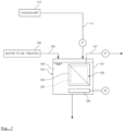
- a twelfth embodiment is a modification of the aforementioned eleventh embodiment, and as shown in FIG. 6 , the membrane separator 11 is installed to the outside of the treatment tank 1.
- the membrane separator 11 includes a plurality of membrane elements 13 provided in the casing 12.
- Each of the membrane elements 13 includes filter membranes, such as hollow fiber membranes.
- a pump 66 for supplying the waste water 2 to an inlet of the membrane separator 11 is installed at a bottom of the treatment tank 1, and an inlet-side flow path 67 is connected between the pump 66 and the inlet of the membrane separator 11.
- an outlet-side flow path 68 for returning the waste water 2 condensed within the membrane separator 11 into the treatment tank 1 is connected to an outlet of the membrane separator 11.
- the waste water 2 is treated with the membrane separation activated sludge method by using the treatment tank 1 as described above.
- the waste water 2 is treated by defining the filtration step for filtering the waste water 2 in the treatment tank 1 by using the membrane elements 13, and the filtration stopping step for stopping the filtration as one treatment cycle, and repeating this treatment cycle.
- the waste water 2 is supplied from the supply flow path 7 to the treatment tank 1, the waste water 2 in the treatment tank 1 is supplied from the inlet-side flow path 67 to the inlet of the membrane separator 11 by driving the pump 66, and the downstream side of the filter membranes of the membrane elements 13 is decompressed. Accordingly, a part of the waste water 2 permeates the filter membranes, and is sent out to the outside of the treatment tank 1 from the permeated water extraction flow path 17 as permeated water 16. On this occasion, the waste water 2 that has not permeated the filter membranes is condensed, and is returned into the treatment tank 1 from the outlet-side flow path 68.
- the filtration by the membrane elements 13 is stopped in the filtration stopping step.
- the water level of the waste water 2 in the treatment tank 1 is maintained between the preset first water level L1 (an example of the ninth threshold value) and the second water level L2 (an example of the tenth threshold value).
- the second water level L2 is lower than the first water level L1.
- the filtration is performed by increasing the membrane-filtered water amount (flux) per membrane area and per time to the maximum design membrane-filtered water amount Qmax (the maximum flux), and the administration of the coagulant 19 from the coagulant administration flow path 20 into the treatment tank 1 is started.
- the administration of the coagulant 19 can be started at an optimum timing at which the load applied to the filter membranes is increased.
- the above-described maximum membrane-filtered water amount Qmax is set to, for example, an amount larger than the above-described inflow 2Q.
- the extraction amount of the permeated water 16 extracted from the permeated water extraction flow path 17 to the outside of the treatment tank 1 exceeds the inflow of the waste water 2 flowing into the treatment tank 1, and the water level of the waste water 2 in the treatment tank 1 gradually falls. Then, when the water level of the waste water 2 in the treatment tank 1 becomes less than the second water level L2, the administration of the coagulant 19 from the coagulant administration flow path 20 into the treatment tank 1 is stopped, and the membrane-filtered water amount is returned to the original extraction flow rate Q from the maximum membrane-filtered water amount Qmax.
- the waste water 2 is listed as an example of the water to be treated, the water to be treated may be water including organic matters other than the waste-water 2, etc.
Landscapes
- Engineering & Computer Science (AREA)
- Water Supply & Treatment (AREA)
- Chemical & Material Sciences (AREA)
- Life Sciences & Earth Sciences (AREA)
- Hydrology & Water Resources (AREA)
- Environmental & Geological Engineering (AREA)
- Organic Chemistry (AREA)
- Chemical Kinetics & Catalysis (AREA)
- Separation Using Semi-Permeable Membranes (AREA)
- Separation Of Suspended Particles By Flocculating Agents (AREA)
Abstract
Description
- The present invention relates to a method of administering a coagulant to be administered in water to be filtered at the time of performing water treatment by filtering the water to be filtered with a filter membrane.
- Conventionally, as this kind of water treatment, for example, the membrane separation activated sludge method is known. In the membrane separation activated sludge method, as shown in
FIG. 7 , aprocessing device 103 is used that provides amembrane separator 102 in afiltration tank 101. - The
membrane separator 102 includes a plurality ofmembrane elements 105 arranged in acasing 104, and anair diffuser 106 that diffuses air from below themembrane elements 105. - Each of the
membrane elements 105 is formed by welding a filter membrane on both front and rear surfaces of a filter plate. The permeated water (treated water) that permeates from the upstream side to the downstream side through a filter membrane is sent out to the outside of thefiltration tank 101 through a permeated waterextraction flow path 107. Additionally, the water to be filtered 108, such as waste water, is supplied from asupply flow path 109 into thefiltration tank 101, and acoagulant 110 is administered from a coagulantadministration flow path 111 to the water to be filtered 108 in thefiltration tank 101. - Accordingly, by supplying the water to be filtered 108 from the
supply flow path 109 into thefiltration tank 101, and filtering the water to be filtered 108 in thefiltration tank 101 with themembrane elements 105, solids-liquid separation of the water to be filtered 108 into sludge and permeated water is performed, and the permeated water is extracted from the permeated waterextraction flow path 107 to the outside of thefiltration tank 101. On this occasion, the surfaces of the filter membranes of themembrane elements 105 are washed by diffusing air with theair diffuser 106. - Additionally, by administering the
coagulant 110 from the coagulantadministration flow path 111 to the water to be filtered 108 in thefiltration tank 101, the coagulant 110 sticks to the sludge surface, and adsorbs organic matters, such as persistent substances. Therefore, membrane blocking of the filter membranes of themembrane elements 105 can be prevented. - Refer to
Japanese Patent Laid-Open No. 2015-163388 A processing devices 103 as described above. - However, in the aforementioned related system, when administering the
coagulant 110 to the water to be filtered 108 in thefiltration tank 101, an optimum timing for starting administration of thecoagulant 110 is not clear. Therefore, there is a risk that the timing for starting administration of thecoagulant 110 is too early, and thecoagulant 110 is excessively administered, or that the timing for starting the administration of thecoagulant 110 is too late, and the dose of thecoagulant 110 is insufficient. - Additionally, after starting the administration of the
coagulant 110, an optimum timing for stopping the administration of thecoagulant 110 is not clear. Therefore, there is a risk that the timing for stopping the administration of thecoagulant 110 is too late, and thecoagulant 110 is excessively administered, or that the timing for stopping the administration of thecoagulant 110 is too early, and the dose of thecoagulant 110 is insufficient. - An object of the present invention is to provide a method of administering a coagulant that can start administration of the coagulant at an optimum timing, and can stop the administration of the coagulant at an optimum timing after starting the administration of the coagulant.
- A method of administering a coagulant in water treatment of the present invention defines one treatment cycle as including a filtration step for using a filter membrane to filter water to be treated in a filtration tank, and a filtration stopping step for stopping filtration, and
- repeats the treatment cycle to treat the water to be treated, wherein a membrane load index is defined as an amount of increase in transmembrane pressure per time in the filtration step, and
- administration of the coagulant into the filtration tank is started when the membrane load index becomes greater than or equal to a first threshold value.
- According to this, the larger the membrane load index, the larger the amount of foulant (soluble organic matters, etc.) contained in the water to be treated. Thus, the permeation ratio resistance at the time when the foulant adheres to the filter membrane surfaces is increased. Therefore, the permeation resistance at the time of permeating the filter membranes is increased, and the load applied to the filter membranes is increased.
- Conversely, the smaller the membrane load index, the smaller the amount of the foulant contained in the water to be treated. Thus, the permeation ratio resistance at the time when the foulant adheres to the filter membrane surfaces is decreased. Therefore, the permeation resistance at the time of permeating the filter membranes is decreased, and the load applied to the filter membranes is decreased.
- In this manner, since the load applied to the filter membranes can be objectively evaluated based on the membrane load index at the time of the filtration step, and the administration of the coagulant is started by using this membrane load index as an index, the administration of the coagulant can be started at an optimum timing.
- A method of administering a coagulant in water treatment of the present invention defines one treatment cycle as including a filtration step for using a filter membrane to filter water to be treated in a filtration tank, and a filtration stopping step for stopping filtration, and
- repeats the treatment cycle to treat the water to be treated, wherein a membrane load index is defined as an amount of increase in transmembrane pressure per time in the filtration step,
- a time point at which a membrane-filtered water amount per time after starting the filtration step of a current treatment cycle is stabilized is defined as a first time point,
- the transmembrane pressure at the first time point is defined as a first transmembrane pressure,
- a time point at which the membrane-filtered water amount per time after starting the filtration step of a treatment cycle immediately before the current treatment cycle is stabilized is defined as a second time point,
- the transmembrane pressure at the second time point is defined as a second transmembrane pressure,
- the difference between the first transmembrane pressure and the second transmembrane pressure is defined as an accumulated additional resistance, and
- when the membrane load index becomes greater than or equal to a first threshold value, and the accumulated additional resistance becomes greater than or equal to a second threshold value, administration of the coagulant into the filtration tank is started.
- A method of administering a coagulant in water treatment of the present invention defines one treatment cycle as including a filtration step for using a filter membrane to filter water to be treated in a filtration tank, and a filtration stopping step for stopping filtration, and repeats the treatment cycle to treat the water to be treated, wherein a membrane load index is defined as an amount of increase in transmembrane pressure per time in the filtration step,
- a time point at which a membrane-filtered water amount per time after starting the filtration step of a current treatment cycle is stabilized is defined as a first time point,
- the transmembrane pressure at the first time point is defined as a first transmembrane pressure,
- a time point at which the membrane-filtered water amount per time after starting the filtration step of a treatment cycle immediately before the current treatment cycle is stabilized is defined as a second time point,
- the transmembrane pressure at the second time point is defined as a second transmembrane pressure,
- a value obtained by dividing the difference between the first transmembrane pressure and the second transmembrane pressure by a time period from the second time point to the first time point is defined as an accumulated additional resistance, and when the membrane load index becomes greater than or equal to a first threshold value, and the accumulated additional resistance becomes greater than or equal to a second threshold value, administration of the coagulant into the filtration tank is started.
- A method of administering a coagulant in water treatment of the present invention defines one treatment cycle as including a filtration step for using a filter membrane to filter water to be treated in a filtration tank, and a filtration stopping step for stopping filtration, and
- repeats the treatment cycle to treat the water to be treated, wherein a membrane load index is defined as an amount of increase in transmembrane pressure per time in the filtration step,
- a time point at which a membrane-filtered water amount per time after starting the filtration step of a current treatment cycle is stabilized is defined as a first time point,
- the transmembrane pressure at the first time point is defined as a first transmembrane pressure,
- a value obtained by dividing the first transmembrane pressure by a membrane-filtered water amount per membrane area and per time is defined as a first filtration resistance value,
- a time point at which the membrane-filtered water amount per time after starting the filtration step of a treatment cycle immediately before the current treatment cycle is stabilized is defined as a second time point,
- the transmembrane pressure at the second time point is defined as a second transmembrane pressure,
- a value obtained by dividing the second transmembrane pressure by the membrane-filtered water amount per membrane area and per time is defined as a second filtration resistance value,
- the difference between the first filtration resistance value and the second filtration resistance value is defined as an accumulated additional resistance, and
- when the membrane load index becomes greater than or equal to a first threshold value, and the accumulated additional resistance becomes greater than or equal to a second threshold value, administration of the coagulant into the filtration tank is started.
- A method of administering a coagulant in water treatment of the present invention defines one treatment cycle as including a filtration step for using a filter membrane to filter water to be treated in a filtration tank, and a filtration stopping step for stopping filtration, and
- repeats the treatment cycle to treat the water to be treated, wherein a membrane load index is defined as an amount of increase in transmembrane pressure per time in the filtration step,
- a time point at which a membrane-filtered water amount per time after starting the filtration step of a current treatment cycle is stabilized is defined as a first time point,
- the transmembrane pressure at the first time point is defined as a first transmembrane pressure,
- a value obtained by dividing the first transmembrane pressure by a membrane-filtered water amount per membrane area and per time is defined as a first filtration resistance value,
- a time point at which the membrane-filtered water amount per time after starting the filtration step of a treatment cycle immediately before the current treatment cycle is stabilized is defined as a second time point,
- the transmembrane pressure at the second time point is defined as a second transmembrane pressure,
- a value obtained by dividing the second transmembrane pressure by the membrane-filtered water amount per membrane area and per time is defined as a second filtration resistance value,
- a value obtained by dividing the difference between the first filtration resistance value and the second filtration resistance value by a time period from the second time point to the first time point is defined as an accumulated additional resistance, and
- when the membrane load index becomes greater than or equal to a first threshold value, and the accumulated additional resistance becomes greater than or equal to a second threshold value, administration of the coagulant into the filtration tank is started.
- According to this, the larger the membrane load index, the larger the amount of foulant (soluble organic matters, etc.) contained in the water to be treated. Thus, the permeation ratio resistance at the time when the foulant adheres to the filter membrane surfaces is increased. Therefore, the permeation resistance at the time of permeating the filter membranes is increased, and the load applied to the filter membranes is increased.
- Conversely, the smaller the membrane load index, the smaller the amount of foulant contained in the water to be treated. Thus, the permeation ratio resistance at the time when the foulant adheres to the filter membrane surfaces is decreased. Therefore, the permeation resistance at the time of permeating the filter membranes is decreased, and the load applied to the filter membranes is decreased.
- In this manner, since the load applied to the filter membranes can be objectively evaluated based on the membrane load index at the time of the filtration step
- Additionally, by diffusing air from below the filter membranes in the filtration stopping step, the foulant adhering to the film surfaces of the filter membranes can be removed, and the filter membranes can be washed.
- On this occasion, the larger the accumulated additional resistance, the fewer the removal amount of the foulant removed from the filter membranes in the filtration stopping step of the treatment cycle (hereinafter referred to as the previous treatment cycle) immediately before the current treatment cycle, and the lower the washing effect of the filter membranes. Therefore, at the start of the filtration step of the current treatment cycle, the amount of the foulant remaining adhered to the filter membranes is large, and the permeability of the filter membranes is decreased.
- Conversely, the smaller the accumulated additional resistance, the larger the removal amount of the foulant removed from the filter membranes in the filtration stopping step of the previous treatment cycle, and the higher the washing effect of the filter membranes. Therefore, at the start of the filtration step of the current treatment cycle, the amount of the foulant remaining adhered to the filter membranes is decreased, and the permeability of the filter membranes is maintained.
- Accordingly, based on the accumulated additional resistance, the washing effect of the filter membranes in the filtration stopping step of the previous treatment cycle can be objectively evaluated.
- In this manner, since the administration of the coagulant is started by using the membrane load index and the accumulated additional resistance as indexes, the administration of the coagulant can be started at an optimum timing.
- According to the method of administering the coagulant of the present invention, it is preferable that, in the filtration step, when the membrane-filtered water amount per membrane area and per time becomes less than a third threshold value, the administration of the coagulant into the filtration tank is stopped.
- According to this, the more the membrane-filtered water amount per membrane area and per time, i.e., the flux (filtration flux), decreases, the smaller the load applied to the filter membranes, and the more the aforementioned membrane-filtered water increases, the larger the load applied to the filter membranes becomes.
- In this manner, since the administration of the coagulant is stopped by using the membrane-filtered water amount per membrane area and per time as the index, the administration of the coagulant can be stopped at an optimum timing after starting the administration of the coagulant.
- A method of administering a coagulant in water treatment of the present invention defines one treatment cycle as including a filtration step for using a filter membrane to filter water to be treated in a treatment tank including a filtration tank having the filter membrane, and a monitoring tank adjacent to the filtration tank, and a filtration stopping step for stopping filtration, and
repeats the treatment cycle to treat the water to be treated, wherein, when an inflow of the water to be treated flowing into the treatment tank from outside exceeds an extraction amount of membrane-filtered water extracted from the filtration tank to the outside of the treatment tank, and thus a water level in the monitoring tank rises and becomes greater than or equal to a fourth threshold value, administration of the coagulant into the filtration tank is started. - According to this, when the inflow of the water to be treated flowing into the treatment tank from the outside exceeds the extraction amount of the membrane-filtered water extracted from the filtration tank to the outside of the treatment tank, and thus the water level of the water to be treated in the monitoring tank rises and becomes greater than or equal to the fourth threshold value, the membrane-filtered water amount (flux) per membrane area and per time is increased, so that the extraction amount of the membrane-filtered water extracted from the filtration tank to the outside of the treatment tank exceeds the inflow of the water to be treated flowing into the treatment tank from the outside. By performing such adjustment of the membrane-filtered water amount, the load applied to the filter membrane is increased.
- Accordingly, by starting the administration of the coagulant when the water level of the water to be treated in the monitoring tank becomes greater than or equal to the fourth threshold value as described above, the administration of the coagulant can be started at an optimum timing.
- According to the method of administering the coagulant of the present invention, it is preferable that, when the water to be treated overflowing from the filtration tank flows into the monitoring tank, and
the water level in the monitoring tank becomes greater than or equal to the fourth threshold value, the administration of the coagulant into the filtration tank is started. - According to the method of administering the coagulant of the present invention, it is preferable that, in the filtration step, when the water level of the water to be treated in the monitoring tank becomes less than the fifth threshold value lower than the fourth threshold value, the administration of the coagulant into the filtration tank is stopped.
- According to this, when the extraction amount of the membrane-filtered water extracted from the filtration tank to the outside of the treatment tank exceeds the inflow of the water to be treated that flows into the treatment tank from the outside, and the water level of the water to be treated in the monitoring tank gradually descends and becomes less than the fifth threshold value, the membrane-filtered water amount (flux) per membrane area and per time is reduced. By performing such adjustment of the membrane-filtered water amount, the load applied to the filter membrane is decreased.
- Accordingly, by stopping the administration of the coagulant when the water level of the water to be treated in the monitoring tank becomes less than the fifth threshold value as described above, the administration of the coagulant can be stopped at an optimum timing after starting the administration of the coagulant.
- A method of administering a coagulant in water treatment of the present invention defines one treatment cycle as including a filtration step for using a filter membrane to filter water to be treated in a treatment tank including a filtration tank having the filter membrane, and a monitoring tank adjacent to the filtration tank, and a filtration stopping step for stopping filtration, and
repeats the treatment cycle to treat the water to be treated, wherein, in the filtration step, when transmembrane pressure becomes greater than or equal to a sixth threshold value, administration of the coagulant into the filtration tank is started. - According to this, the larger the transmembrane pressure, the larger the load applied to the filter membrane. Therefore, the load applied to the filter membrane can be objectively evaluated based on the transmembrane pressure. Since the administration of the coagulant is started by using this transmembrane pressure as an index, the administration of the coagulant can be started at an optimum timing.
- According to the method of administering the coagulant of the present invention, it is preferable to stop the administration of the coagulant when a predetermined time period elapses after starting the administration of the coagulant.
- According to the method of administering the coagulant of the present invention, it is preferable that the predetermined time period is a time period obtained by multiplying an actual residence time of the filtration tank in which the filter membrane is immersed by a value obtained by adding 1 to a circulation ratio,
- the actual residence time is a time period required for the coagulant administered to a predetermined administration position of the filtration tank to flow from the filtration tank and return to an original administration position of the filtration tank through the monitoring tank,
- the circulation ratio is a value obtained by dividing a circulation amount by an inflow of the water to be treated, and
- the circulation amount is a flow rate per time of the water to be treated flowing into the monitoring tank from the filtration tank.
- According to this, by stopping the administration of the coagulant into the filtration tank after the predetermined time period elapses after starting the administration of the coagulant, the administration of the coagulant can be stopped at an optimum timing after starting the administration of the coagulant.
- A method of administering a coagulant in water treatment of the present invention defines one treatment cycle as including a filtration step for using a filter membrane to filter water to be treated in a filtration tank, and a filtration stopping step for stopping filtration, and repeats the treatment cycle to treat the water to be treated, wherein, in the filtration step, when a membrane-filtered water amount per membrane area and per time becomes greater than or equal to a seventh threshold value, administration of the coagulant into the filtration tank is started.
- According to this, the more the membrane-filtered water amount per membrane area and per time, i.e., the flux (filtration flux), increases, the larger the load applied to the filter membranes becomes. Therefore, by starting the administration of the coagulant by using this membrane-filtered water amount as an index, the administration of the coagulant can be started at an optimum timing.
- According to the method of administering the coagulant of the present invention, it is preferable that, in the filtration step, when the membrane-filtered water amount per membrane area and per time becomes less than an eighth threshold value lower than the seventh threshold value, the administration of the coagulant into the filtration tank is stopped.
- According to this, the more the membrane-filtered water amount per membrane area and per time is decreased, the smaller the load applied to the filter membrane becomes. Therefore, by stopping the administration of the coagulant by using this membrane-filtered water amount as the index, after starting the administration of the coagulant, the administration of the coagulant can be stopped at an optimum timing.
- A method of administering a coagulant in water treatment of the present invention defines one treatment cycle as including a filtration step for using a filter membrane to filter water to be treated that is supplied to a treatment tank from outside, and a filtration stopping step for stopping filtration, and
repeats the treatment cycle to treat the water to be treated, wherein, when an inflow of the water to be treated flowing into the treatment tank from the outside exceeds an extraction amount of membrane-filtered water that permeates the filter membrane and is extracted to the outside of the treatment tank, and thus a water level in the treatment tank rises and becomes greater than or equal to a ninth threshold value, administration of the coagulant into the treatment tank is started. - According to this, when the inflow of the above-described water to be treated exceeds the extraction amount of the above-described membrane-filtered water, and the water level in the treatment tank becomes greater than or equal to the ninth threshold value, the membrane-filtered water amount (flux) per membrane area and per time is increased, so that the extraction amount of the above-described membrane-filtered water exceeds the inflow of the above-described water to be treated. By performing such adjustment of the membrane-filtered water amount, the load applied to the filter membrane is increased.
- Accordingly, by starting the administration of the coagulant when the water level in the treatment tank becomes greater than or equal to the ninth threshold value as described above, the administration of the coagulant can be started at an optimum timing.
- According to the method of administering the coagulant of the present invention, it is preferable that, in the filtration step, when the water level of the water to be treated in the treatment tank becomes less than a tenth threshold value lower than the ninth threshold value, the administration of the coagulant into the treatment tank is stopped.
- According to this, when the extraction amount of the membrane-filtered water that permeates the filter membrane and is extracted to the outside of the treatment tank exceeds the inflow of the water to be treated flowing into the treatment tank from the outside, and the water level of the water to be treated in the treatment tank gradually descends and becomes less than the tenth threshold value, the membrane-filtered water amount (flux) per membrane area and per time is reduced. By performing such adjustment of the membrane-filtered water amount, the load applied to the filter membrane is decreased.
- Accordingly, by stopping the administration of the coagulant when the water level in the treatment tank becomes less than the tenth threshold value as described above, the administration of the coagulant can be stopped at an optimum timing after starting the administration of the coagulant.
- As described above, according to the present invention, the administration of the coagulant can be started at an optimum timing, and the administration of the coagulant can be stopped at an optimum timing after starting the administration of the coagulant.
-
- [
FIG. 1] FIG. 1 is a schematic diagram of a water treatment device in first to fifth embodiments of the present invention. - [
FIG. 2] FIG. 2 is a graph showing changes in transmembrane pressure versus time, in a method of administering a coagulant using the water treatment device in the first to fifth embodiments of the present invention. - [
FIG. 3] FIG. 3 is a graph showing changes in permeability versus time, in the method of administering the coagulant using the water treatment device in the first to fifth embodiments of the present invention. - [
FIG. 4] FIG. 4 is a schematic diagram of a water treatment device in sixth to tenth embodiments of the present invention. - [
FIG. 5] FIG. 5 is a schematic diagram of a water treatment device in an eleventh embodiment of the present invention. - [
FIG. 6] FIG. 6 is a schematic diagram of a water treatment device in a twelfth embodiment of the present invention. - [
FIG. 7] FIG. 7 is a schematic diagram of a conventional water treatment device. - Hereinafter, embodiments in the present invention will be described with reference to the drawings.
- In a first embodiment, as shown in
FIG. 1 , atreatment tank 1 is a tank that processes waste water 2 (an example of water to be filtered) including an organic matter, etc., and includes afiltration tank 3, and amonitoring tank 4 adjacent to thefiltration tank 3. Thefiltration tank 3 and themonitor tank 4 are divided via an overflow weir 5. - The
waste water 2 is supplied from asupply flow path 7 to thefiltration tank 3. Thewaste water 2 supplied to thefiltration tank 3 overflows the overflow weir 5, and flows into theadjacent monitoring tank 4. Apump 8 is provided in themonitoring tank 4. Areturn flow path 9 for returning thewaste water 2 in themonitoring tank 4 to thefiltration tank 3 is connected to thepump 8. - A submerged
membrane separator 11 is installed in thefiltration tank 3. Themembrane separator 11 includes a plurality ofmembrane elements 13 provided in acasing 12, and anair diffuser 14 provided below themembrane elements 13. - Each of the
membrane elements 13 includes a filter plate, and filter membranes welded on both front and rear surfaces of the filter plate. Thewaste water 2 that permeates from a upstream side to a downstream side through the filter membranes is sent out to the outside of thefiltration tank 1 as permeatedwater 16 through a permeated waterextraction flow path 17. Additionally, acoagulant 19 is administered from a coagulantadministration flow path 20 to thewaste water 2 in thefiltration tank 3. - The
waste water 2 is processed with the membrane separation activated sludge method by using thetreatment tank 1 as described above. On this occasion, as shown inFIG. 2 , a filtration step J for using themembrane elements 13 to filter thewaste water 2 in thefiltration tank 3, and a filtration stopping step K for stopping filtration are defined as one treatment cycle, and thewaste water 2 is treated by repeating these treatment cycles C1 to C5. - In the filtration step J, the
waste water 2 is supplied from thesupply flow path 7 to thefiltration tank 3, and the downstream side of the filter membranes of themembrane elements 13 are decompressed while diffusing air from theair diffuser 14 of themembrane separator 11. Accordingly, a part of thewaste water 2 in thefiltration tank 3 permeates the filter membranes, and is sent out to the outside of thetreatment tank 1 from the permeated waterextraction flow path 17 as permeatedwater 16. - Additionally, the
waste water 2 in thefiltration tank 3 overflows the overflow weir 5, and flows into theadjacent monitoring tank 4. Further, thewaste water 2 in themonitoring tank 4 is returned to thefiltration tank 3 through thereturn flow path 9 by driving thepump 8. Additionally, in the filtration stopping step K, the filtration by themembrane elements 13 is stopped while continuing air diffusion from theair diffuser 14. - When treating the
waste water 2 by repeating the treatment cycles C1 to C5 as described above, by administering thecoagulant 19 from the coagulantadministration flow path 20 to thewaste water 2 in thefiltration tank 3, thecoagulant 19 sticks to activated sludge in thewaste water 2, and a coarse flock is formed. - Such a method of administering the
coagulant 19 will be described below. -
FIG. 2 is a graph showing changes in transmembrane pressure of themembrane elements 13 for each treatment cycle, and a vertical axis represents the transmembrane pressure, and a horizontal axis represents time during which treatment cycles C1, C2, C3 ... are performed. Here, the amount of increase of the transmembrane pressure per time in the filtration step J is defined as a membrane load index A. That is, as shown inFIG. 2 , a time point at which the amount of the membrane-filtered water per time is stabilized immediately after starting the filtration step J is defined as t1, the transmembrane pressure at this time point t1 is defined as an transmembrane pressure p1 in a beginning period, and the transmembrane pressure at a time point t2 immediately before ending the filtration step J is defined as an transmembrane pressure p2 in an end period. Then, when the difference between the transmembrane pressure p1 in the beginning period and the transmembrane pressure p2 in the end period (that is, p2 - p1) is defined as Δp, and the time between both the time points t1 and t2 is defined as Δt, the membrane load index A [Pa/minute] is represented by a relational expression:
- The time point t1 at which the amount of the membrane-filtered water per time immediately after starting the filtration step J is stabilized means a time point at which the amount of the membrane-filtered water per time is settled down to a predetermined flux that is set in advance.
- Then, when repeating the treatment cycle a plurality of times, for example, as shown in
FIG. 2 , in the treatment cycle C3, when the membrane load index A obtained as described above becomes greater than or equal to a predetermined membrane load index A1 (an example of a first threshold value), the administration of thecoagulant 19 from the coagulantadministration flow path 20 into thefiltration tank 3 is started. - At the start of the administration of the
coagulant 19, only an initial dose D [mg/liter] of thecoagulant 19 is administered. The initial dose D is represented by a relational expression:
- Here, E1 and E2 are constants. Additionally, F is the amount of the membrane-filtered water per unit membrane area and per unit time of the filter membrane (that is, flux [m3/m2/minute]).
- Thereafter, when the membrane load index A falls less than or equal to a target membrane load index A2, the dose of the
coagulant 19 is reduced by a predetermined percentage from the initial dose D. The target membrane load index A2 is set to be a numerical value smaller than the predetermined membrane load index A1. - Thereafter, in the filtration step, when a membrane-filtered water amount F (flux) per unit membrane area and per unit time becomes less than a predetermined membrane-filtered water amount Fs (an example of the third threshold value), the administration of the
coagulant 19 from the coagulantadministration flow path 20 into thefiltration tank 3 is stopped. - According to the method of administering the
coagulant 19 as described above, the larger the membrane load index A, the larger the amount of the foulant (soluble organic matters, etc.) contained in thewaste water 2. Thus, the permeation ratio resistance at the time when the foulant adheres to the filter membrane surfaces is increased. Therefore, the permeation resistance at the time of permeating the filter membranes of themembrane elements 13 is increased, and the load applied to the filter membranes is increased. - Conversely, the smaller the membrane load index A, the smaller the amount of the foulant contained in the
waste water 2. Thus, the permeation ratio resistance at the time when the foulant adheres to the filter membrane surfaces is decreased. Therefore, the permeation resistance at the time of permeating the filter membranes is decreased, and the load applied to the filter membranes is decreased. - In this manner, since the load applied to the filter membranes of the
membrane elements 13 can be objectively evaluated based on the membrane load index A at the time of the filtration step J, and the administration of thecoagulant 19 is started by using this membrane load index A as an index, the administration of thecoagulant 19 can be started at an optimum timing at which the load applied to the filter membranes is increased. - Additionally, the more the membrane-filtered water amount F at the filtration step J decreases, the smaller the load applied to the filter membranes of the
membrane elements 13, and the more the membrane-filtered water amount F increases, the larger the load applied to the filter membranes becomes. In this manner, since the administration of thecoagulant 19 is stopped by using the membrane-filtered water amount F as the index, the administration of thecoagulant 19 can be stopped at an optimum timing at which the load applied to the filter membranes is decreased. - In a method of administering the
coagulant 19 of a second embodiment, the administration of thecoagulant 19 is started by using an accumulated additional resistance B as an index, in addition to the membrane load index A illustrated in the above-described first embodiment. - The accumulated additional resistance B is obtained as follows.
-
FIG. 3 is a graph illustrating changes in the permeability of filter membranes, and a vertical axis represents the permeability, and a horizontal axis represents time during which treatment cycles are performed. The permeability is indicated by the following relational expressions.
permeability = flux/transmembrane pressure - Here, the time point at which the amount of the membrane-filtered water per time after starting the filtration step J of a currently performed treatment cycle C(n) (hereinafter referred to as the current treatment cycle C(n)) is stabilized is defined as a first time point T1, and the permeability at the first time point T1 is defined as first permeability Prm1. Additionally, the time point at which the amount of the membrane-filtered water per time after starting the filtration step J of a treatment cycle C(n-1) (hereinafter referred to as the previous treatment cycle C(n-1)) immediately before the current treatment cycle C(n) is stabilized is defined as a second time point T2, and the permeability in the second time point T2 is defined as second permeability Prm2. The inverse number of the above-described first permeability Prm1 is defined as a first filtration resistance value, and the inverse number of the above-described second permeability Prm2 is defined as a second filtration resistance value. That is, when the transmembrane pressure at the first time point T1 is defined as a first transmembrane pressure, the value obtained by dividing the first transmembrane pressure by the flux (the amount of the membrane-filtered water per membrane area and per time) is the first filtration resistance value. Additionally, when the transmembrane pressure at the second time point T2 is defined as a second transmembrane pressure, the value obtained by dividing the second transmembrane pressure by the flux (the amount of the membrane-filtered water per membrane area and per time) is the second filtration resistance value.
- When the time from the second time point T2 to the first time point T1 is defined as ΔT, the accumulated additional resistance B is defined as "the value obtained by dividing the difference between the first filtration resistance value and the second filtration resistance value by the time from the second time point T2 to the first time point T1." That is, the accumulated additional resistance B is represented by the following relational expression.

- Then, when the membrane load index A becomes greater than or equal to the predetermined membrane load index A1 (an example of the first threshold value), and when the accumulated additional resistance B obtained as described above becomes greater than or equal to the predetermined accumulated additional resistance B1 (an example of a second threshold value), the administration of the
coagulant 19 from the coagulantadministration flow path 20 into thefiltration tank 3 is started. - At the start of the administration of the
coagulant 19, only the initial dose D of thecoagulant 19 is administered, and thereafter, when the membrane load index A falls less than or equal to the target membrane load index A2, the dose of thecoagulant 19 is reduced by a predetermined percentage from the initial dose D. - Thereafter, in the filtration step, when the membrane-filtered water amount F per membrane area and per unit time becomes less than the predetermined membrane-filtered water amount Fs, the administration of the
coagulant 19 from the coagulantadministration flow path 20 into thefiltration tank 3 is stopped. - According to the method of administering the
coagulant 19 as described above, the load applied to the filter membranes can be objectively evaluated based on the membrane load index A at the time of the filtration step. - Additionally, the
air diffuser 14 diffuses air from below themembrane elements 13 in the filtration stopping step K. Thus, the foulant adhering to the membrane surfaces of the filter membranes can be removed, and the filter membranes can be washed. - On this occasion, the larger the accumulated additional resistance B, the less the removal amount of the foulant removed from the filter membranes in the filtration stopping step K of the previous treatment cycle C(n-1), and the lower the washing effect of the filter membranes. Therefore, at the start of the filtration step J of the current treatment cycle C(n), the amount of the foulant remaining adhered to the filter membranes is large, and the permeability of the filter membranes is decreased.
- Conversely, the smaller the accumulated additional resistance B, the larger the removal amount of the foulant removed from the filter membranes in the filtration stopping step K of the previous treatment cycle C(n-1), and the higher the washing effect of the filter membranes. Therefore, at the start of the filtration step J of the current treatment cycle C(n), the amount of the foulant remaining adhered to the filter membranes is decreased, and the permeability of the filter membranes is improved.
- Accordingly, the washing effect of the filter membranes in the filtration stopping step K of the previous treatment cycle C(n-1) can be objectively evaluated based on the accumulated additional resistance B.
- In this manner, the administration of the
coagulant 19 is started by using the membrane load index A and the accumulated additional resistance B as the indexes. Therefore, the administration of thecoagulant 19 can be started at an optimum timing at which the load applied to the filter membranes is increased. - Additionally, the administration of the
coagulant 19 is stopped by using the membrane-filtered water amount F as the index. Therefore, after starting the administration of thecoagulant 19, the administration of thecoagulant 19 can be stopped at an optimum timing at which the load applied to the filter membranes is decreased. - In the above-described second embodiment, the description has been given by using the value obtained by dividing the difference between the first filtration resistance value and the second filtration resistance value by the time from the second time point T2 to the first time point T1 as the accumulated additional resistance B. However, the difference between the first filtration resistance value and the second filtration resistance value may be defined as the accumulated additional resistance B. Alternatively, the value obtained by dividing the difference between the transmembrane pressure at the first time point T1 of the current treatment cycle C(n) and the transmembrane pressure at the second time point T2 of the previous treatment cycle C(n-1) by the time from the second time point T2 to the first time point T1 may be defined as the accumulated additional resistance B. Additionally, the difference between the transmembrane pressure at the above-described first time point T1 and the transmembrane pressure at the above-described second time point T2 may be defined as the accumulated additional resistance B.
- In a method of administering the
coagulant 19 of a third embodiment, as shown inFIG. 1 , the administration of thecoagulant 19 is started and stopped by using the water level of thewaste water 2 in themonitoring tank 4 as an index. - In the filtration step, the
waste water 2 is filtered by using themembrane elements 13, while circulating thewaste water 2 between thefiltration tank 3 and themonitoring tank 4. - For example, when the inflow per unit time of the
waste water 2 supplied from thesupply flow path 7 to thefiltration tank 3 is Q [m3/minute], the extraction flow rate per unit time of the permeatedwater 16 extracted from the permeated waterextraction flow path 17 is defined as Q [m3/minute], and the flow rate per time of thewaste water 2 returned from themonitoring tank 4 to thefiltration tank 3 through thereturn flow path 9 is defined as 3Q [m3/minute]. As a result, it is assumed that the flow rate per unit time of thewaste water 2 that overflows the overflow weir 5 from thefiltration tank 3 and flows out to themonitoring tank 4 is adjusted to be 3Q [m3/minute] . - On this occasion, the water level of the
waste water 2 in themonitoring tank 4 is maintained between a preset first water level L1 (an example of a fourth threshold value) and a second water level L2 (an example of a fifth threshold value). The second water level L2 is lower than the first water level L1. - Thereafter, when the inflow per unit time of the
waste water 2 supplied from thesupply flow path 7 to thefiltration tank 3 is increased from Q [m3/minute] to, for example, 2Q [m3/minute], the increase in the filtration amount cannot keep up with the increase in the inflow, and the water level of thewaste water 2 in themonitoring tank 4 rises. - Therefore, when the water level of the
waste water 2 in themonitoring tank 4 becomes greater than or equal to the first water level L1, filtration is performed by increasing the membrane-filtered water amount (flux) per membrane area and per time to the maximum design membrane-filtered water amount Qmax (the maximum flux), so that the extraction amount of the membrane-filtered water extracted from the permeated waterextraction flow path 17 exceeds the inflow of thewaste water 2 supplied from thesupply flow path 7 to thefiltration tank 3. By performing such adjustment of the membrane-filtered water amount, the load applied to the filter membranes is increased. - Accordingly, when the water level of the
waste water 2 in themonitoring tank 4 becomes greater than or equal to the first water level L1 as described above, by starting the administration of thecoagulant 19 from the coagulantadministration flow path 20 into thefiltration tank 3, the administration of thecoagulant 19 can be started at an optimum timing at which the load applied to the filter membranes is increased. In this case, although there is a certain upper limit, the above-described maximum membrane-filtered water amount Qmax is set to, for example, an amount larger than the above-described inflow 2Q. - When the filtration is continued by setting the membrane-filtered water amount to the maximum design membrane-filtered water amount Qmax as described above, and the water level of the
waste water 2 in themonitoring tank 4 falls less than the second water level L2, the filtration is performed by reducing the membrane-filtered water amount (flux) per membrane area and per time from the maximum membrane-filtered water amount Qmax to the original extraction flow rate Q. By performing such adjustment of the membrane-filtered water amount, the load applied to the filter membrane is decreased. - Accordingly, when the water level of the
waste water 2 in themonitoring tank 4 becomes less than the second water level L2 as described above, by stopping the administration of thecoagulant 19 from the coagulantadministration flow path 20 into thefiltration tank 3, after starting the administration of thecoagulant 19, the administration of thecoagulant 19 can be stopped at an optimum timing at which the load applied to the filter membranes is decreased. - In a method of administering the
coagulant 19 of a fourth embodiment, the administration of thecoagulant 19 is started and stopped by using the transmembrane pressure of the filter membranes of themembrane elements 13 and the passage of a predetermined time period as indexes. There is a residence time Ts as an example of the predetermined time period. The residence time Ts is defined by actual residence time × (circulation ratio + 1). - Here, as indicated by dotted line arrows in
FIG. 1 , the actual residence time is the time required for thecoagulant 19 administered to apredetermined administration position 23 of thefiltration tank 3 to flow from thefiltration tank 3 over the overflow weir 5 into themonitoring tank 4, and to return from themonitoring tank 4 to theoriginal administration position 23 of thefiltration tank 3 through thereturn flow path 9. - Additionally, the circulation ratio is the value obtained by dividing a circulation amount by the inflow of the
waste water 2 per time (that is, the circulation amount/the inflow of thewaste water 2 per time). The above-described inflow of thewaste water 2 is the amount of thewaste water 2 flowing into thefiltration tank 3 from thesupply flow path 7. Additionally, the circulation amount is the flow rate per time of thewaste water 2 that flows from thefiltration tank 3 over the overflow weir 5 into themonitoring tank 4. - In the filtration step, the
waste water 2 is filtered by using themembrane elements 13, while circulating thewaste water 2 between thefiltration tank 3 and themonitoring tank 4. On this occasion, for example, when the inflow per unit time of thewaste water 2 supplied from thesupply flow path 7 to thefiltration tank 3 is defined as Q [m3/minute], the flow rate per unit time of the permeatedwater 16 extracted from the permeated waterextraction flow path 17 is defined as Q [m3/minute], the flow rate per unit time of thewaste water 2 that overflows from thefiltration tank 3 and flows into themonitoring tank 4 over the overflow weir 5 is defined as 3Q [m3/minute], the flow rate per time of thewaste water 2 flowing into thefiltration tank 3 through thereturn flow path 9 from themonitoring tank 4 is defined as 3Q [m3/minute], and the actual residence time is defined as 70 [minutes], the circulation amount is 3Q [m3/minute], and the membrane-filtered water amount per time (that is, the flow rate per unit time of the permeatedwater 16 extracted from the permeated water extraction flow path 17) is Q [m3/minute]. Accordingly, the circulation ratio is 3Q/Q = 3. The residence time Ts is 70 × (3 + 1) = 280 [minutes]. - In the filtration step, when the transmembrane pressure of the filter membranes of the
membrane elements 13 becomes greater than or equal to a predetermined transmembrane pressure (an example of a sixth threshold value), the administration of thecoagulant 19 from the coagulantadministration flow path 20 into thefiltration tank 3 is started. - According to this, the larger the transmembrane pressure, the larger the load applied to the filter membranes. Therefore, the load applied to the filter membranes can be objectively evaluated based on the transmembrane pressure. Since the administration of the
coagulant 19 is started by using this transmembrane pressure as an index, the administration of thecoagulant 19 can be started at an optimum timing at which the load applied to the filter membranes is increased. - When the residence time Ts (an example of the predetermined time period) elapses after starting the administration of the
coagulant 19 in this manner, the administration of thecoagulant 19 into thefiltration tank 3 is stopped. Accordingly, after starting the administration of thecoagulant 19, the administration of thecoagulant 19 can be stopped at an optimum timing at which the load applied to the filter membranes is decreased. - In a method of administering the
coagulant 19 of a fifth embodiment, the administration of thecoagulant 19 is started and stopped by using the membrane-filtered water amount per membrane area and per time (that is, the flux [m3/m2/minute]) of the filter membranes of themembrane elements 13 as an index. - That is, in the filtration step, when the above-described membrane-filtered water amount becomes greater than or equal to the preset first membrane-filtered water amount (an example of a seventh threshold value), the administration of the
coagulant 19 from the coagulantadministration flow path 20 into thefiltration tank 3 is started. - According to this, the more the membrane-filtered water amount is increased, the larger the load applied to the filter membranes becomes. Therefore, by starting the administration of the
coagulant 19 by using this membrane-filtered water amount as the index, the administration of thecoagulant 19 can be started at an optimum timing at which the load applied to the filter membranes is increased. - Thereafter, in the filtration step, when the membrane-filtered water amount becomes less than the preset second membrane-filtered water amount (an example of an eighth threshold value), the administration of the
coagulant 19 from the coagulantadministration flow path 20 into thefiltration tank 3 is stopped. The second membrane-filtered water amount is set to be a water amount smaller than the first membrane-filtered water amount. - According to this, the more the membrane-filtered water amount is decreased, the smaller the load applied to the filter membranes becomes. Therefore, by stopping the administration of the
coagulant 19 by using this membrane-filtered water amount as the index, after starting the administration of thecoagulant 19, the administration of thecoagulant 19 can be stopped at an optimum timing at which the load applied to the filter membrane is decreased. - A water treatment device of sixth embodiment will be described based on
FIG. 4 . Note that members that are the same as the members in the aforementioned first to fifth embodiments will be denoted by the same signs, and a detailed description will be omitted. - A
treatment tank 50 includes thefiltration tank 3, and an anoxia tank 51 (an example of the monitoring tank) adjacent to thefiltration tank 3. Thefiltration tank 3 is an aerobic tank. Thefiltration tank 3 and theanoxia tank 51 are divided via the overflow weir 5. Thepump 8 is provided in theanoxia tank 51. Adelivery flow path 52 for sending thewaste water 2 in theanoxia tank 51 into thefiltration tank 3 is connected to thepump 8. - The
waste water 2 is supplied from thesupply flow path 7 to theanoxia tank 51, and sent from theanoxia tank 51 into thefiltration tank 3 through thedelivery flow path 52 by thepump 8. Thereafter, a part of thewaste water 2 overflows from the inside of thefiltration tank 3 over the overflow weir 5 to be returned to theanoxia tank 51. - The submerged
membrane separator 11 is installed in thefiltration tank 3. - The
waste water 2 is treated with the membrane separation activated sludge method by using thetreatment tank 50 as described above. On this occasion, thewaste water 2 is treated by defining the filtration step and the filtration stopping step as one treatment cycle, and repeating this treatment cycle. - In the filtration step, the
waste water 2 is supplied from thesupply flow path 7 to theanoxia tank 51, thewaste water 2 in theanoxia tank 51 is sent from thedelivery flow path 52 into thefiltration tank 3 by driving thepump 8, and the downstream side of the filter membranes of themembrane elements 13 is decompressed, while diffusing air from theair diffuser 14 of themembrane separator 11. Accordingly, a part of thewaste water 2 in thefiltration tank 3 permeates the filter membranes, and is sent out to the outside of thetreatment tank 1 from the permeated waterextraction flow path 17 as the permeatedwater 16. - Additionally, the
waste water 2 in thefiltration tank 3 overflows the overflow weir 5 to be returned to theadjacent anoxia tank 51. Accordingly, thewaste water 2 circulates between thefiltration tank 3 and theanoxia tank 51, ammonia nitrogen in thewaste water 2 is nitrified in thefiltration tank 3 to become nitric acid, and the nitric acid is denitrified in theanoxia tank 51 to become nitrogen gas. - Additionally, in the filtration stopping step, the filtration by the
membrane elements 13 is stopped, while continuing air diffusion from theair diffuser 14. - When treating the
waste water 2 by repeating the treatment cycles as described above, by administering thecoagulant 19 from the coagulantadministration flow path 20 into thewaste water 2 in thefiltration tank 3, thecoagulant 19 sticks to the activated sludge in thewaste water 2, and a coarse flock is formed. - As such a method of administering the
coagulant 19, similar to the aforementioned first embodiment, when the membrane load index A becomes greater than or equal to the predetermined membrane load index A1 (an example of the first threshold value), the administration of thecoagulant 19 from the coagulantadministration flow path 20 into thefiltration tank 3 is started. At the start of the administration of thecoagulant 19, only the initial dose D of thecoagulant 19 is administered. - Thereafter, when the membrane load index A falls less than or equal to the target membrane load index A2, the dose of the
coagulant 19 is reduced by a predetermined percentage from the initial dose D. The target membrane load index A2 is set to be a numerical value smaller than the predetermined membrane load index A1. - Thereafter, in the filtration step, when the membrane-filtered water amount F (flux) per unit membrane area and per unit time becomes less than the predetermined membrane-filtered water amount Fs (an example of the third threshold value), the administration of the
coagulant 19 from the coagulantadministration flow path 20 into thefiltration tank 3 is stopped. - According to the method of administering the
coagulant 19 as described above, the load applied to the filter membranes of themembrane elements 13 can be objectively evaluated based on the membrane load index A at the time of the filtration step, and the administration of thecoagulant 19 is started by using this membrane load index A as the index. Therefore, the administration of thecoagulant 19 can be started at an optimum timing. - Additionally, the administration of the
coagulant 19 is stopped by using the membrane-filtered water amount F as the index. Therefore, the administration of thecoagulant 19 can be stopped at an optimum timing after starting the administration of thecoagulant 19. - In a seventh embodiment, as the method of administering the
coagulant 19, in the water treatment device shown inFIG. 4 , similar to the aforementioned second embodiment, the administration of thecoagulant 19 is started by using the membrane load index A and the accumulated additional resistance B as the indexes. - That is, when the membrane load index A becomes greater than or equal to the predetermined membrane load index A1 (an example of the first threshold value), and the accumulated additional resistance B becomes greater than or equal to the predetermined accumulated additional resistance B1 (an example of the second threshold value), the administration of the
coagulant 19 from the coagulantadministration flow path 20 into thefiltration tank 3 is started. - At the start of the administration of the
coagulant 19, only the initial dose D of thecoagulant 19 is administered, and thereafter, when the membrane load index A falls less than the target membrane load index A2, the dose of thecoagulant 19 is reduced by a predetermined percentage from the initial dose D. - Thereafter, in the filtration step, when the membrane-filtered water amount F per membrane area and per unit time becomes less than the predetermined membrane-filtered water amount Fs, the administration of the
coagulant 19 from the coagulantadministration flow path 20 into thefiltration tank 3 is stopped. - According to the method of administering the
coagulant 19 as described above, the load applied to the filter membranes can be objectively evaluated based on the membrane load index A at the time of the filtration step, and the washing effect of the filter membranes in the filtration stopping step of the previous treatment cycle can be objectively evaluated based on the accumulated additional resistance B. - In this manner, since the administration of the
coagulant 19 is started by using the membrane load index A and the accumulated additional resistance B as the indexes, the administration of thecoagulant 19 can be started at an optimum timing. - Additionally, the administration of the
coagulant 19 is stopped by using the membrane-filtered water amount F as the index. Therefore, after starting the administration of thecoagulant 19, the administration of thecoagulant 19 can be stopped at an optimum timing. - In an eighth embodiment, as the method of administering the
coagulant 19, in the water treatment device shown inFIG. 4 , similar to the aforementioned third embodiment, the administration of thecoagulant 19 is started and stopped by using the water level of thewaste water 2 in the anoxia tank 51 (monitoring tank) as the index. - In the filtration step, the
waste water 2 is filtered by using themembrane elements 13, while circulating thewaste water 2 between thefiltration tank 3 and theanoxia tank 51. - For example, it is assumed that, when the inflow per unit time of the
waste water 2 supplied from thesupply flow path 7 to theanoxia tank 51 is Q [m3/minute], the flow rate per unit time of thewaste water 2 sent from theanoxia tank 51 to thefiltration tank 3 through thedelivery flow path 52 is defined as 4Q [m3/minute], the extraction flow rate per unit time of the permeatedwater 16 extracted from the permeated waterextraction flow path 17 is defined as Q [m3/minute], and the flow rate per unit time of thewaste water 2 that overflows the overflow weir 5 from thefiltration tank 3 to be returned to theanoxia tank 51 is adjusted to be 3Q [m3/minute]. - On this occasion, the water level of the
waste water 2 in theanoxia tank 51 is maintained between the preset first water level L1 (an example of the fourth threshold value) and the second water level L2 (an example of the fifth threshold value). The second water level L2 is lower than the first water level L1. - Thereafter, when the inflow per unit time of the
waste water 2 supplied from thesupply flow path 7 to theanoxia tank 51 is increased from Q [m3/minute] to, for example, 2Q [m3/minute], the increase in the filtration amount cannot keep up with the increase in the inflow, and the water level of thewaste water 2 in theanoxia tank 51 rises. - Therefore, when the water level of the
waste water 2 in theanoxia tank 51 becomes greater than or equal to the first water level L1, filtration is performed by increasing the membrane-filtered water amount (flux) per membrane area and per time to the maximum design membrane-filtered water amount Qmax (the maximum flux), so that the extraction amount of the membrane-filtered water extracted from the permeated waterextraction flow path 17 exceeds the inflow of thewaste water 2 supplied from thesupply flow path 7 to theanoxia tank 51. By performing such adjustment of the membrane-filtered water amount, the load applied to the filter membrane is increased. - Accordingly, when the water level of the
waste water 2 in theanoxia tank 51 becomes greater than or equal to the first water level L1 as described above, by starting the administration of thecoagulant 19 from the coagulantadministration flow path 20 into thefiltration tank 3, the administration of thecoagulant 19 can be started at an optimum timing at which the load applied to the filter membranes is increased. In this case, although there is a certain upper limit, the above-described maximum membrane-filtered water amount Qmax is set to, for example, an amount larger than the above-described inflow 2Q. - When the filtration is continued by setting the membrane-filtered water amount to the maximum design membrane-filtered water amount Qmax as described above, and the water level of the
waste water 2 in theanoxia tank 51 falls less than the second water level L2, the filtration is performed by reducing the membrane-filtered water amount (flux) per membrane area and per time from the maximum membrane-filtered water amount Qmax to the original extraction flow rate Q. By performing such adjustment of the membrane-filtered water amount, the load applied to the filter membrane is decreased. - Accordingly, when the water level of the
waste water 2 in theanoxia tank 51 becomes less than the second water level L2 as described above, by stopping the administration of thecoagulant 19 from the coagulantadministration flow path 20 into thefiltration tank 3, after starting the administration of thecoagulant 19, the administration of thecoagulant 19 can be stopped at an optimum timing at which the load applied to the filter membranes is decreased. - In a ninth embodiment, as the method of administering the
coagulant 19, in the water treatment device shown inFIG. 4 , similar to the aforementioned fourth embodiment, the administration of thecoagulant 19 is started and stopped by using the transmembrane pressure of the filter membranes of themembrane elements 13 and the passage of a predetermined time period as the indexes. There is the residence time Ts as an example of the predetermined time period. The residence time Ts is defined by the actual residence time x (the circulation ratio + 1). - Here, as indicated by dotted line arrows in
FIG. 4 , the actual residence time is the time required for thecoagulant 19 administered to thepredetermined administration position 23 of thefiltration tank 3 to circulate in thefiltration tank 3, to flow from thefiltration tank 3 over the overflow weir 5 into theanoxia tank 51, and to return from theanoxia tank 51 to theoriginal administration position 23 of thefiltration tank 3 through thedelivery flow path 52. - Additionally, the circulation ratio is the circulation amount/the inflow of the
waste water 2 per time. The above-described inflow of thewaste water 2 is the amount of thewaste water 2 flowing into theanoxia tank 51 from thesupply flow path 7. Additionally, the circulation amount is the flow rate per time of thewaste water 2 flowing from thefiltration tank 3 over the overflow weir 5 into theanoxia tank 51. - In the filtration step, the
waste water 2 is filtered by using themembrane elements 13, while circulating thewaste water 2 between thefiltration tank 3 and theanoxia tank 51. On this occasion, for example, when the inflow per unit time of thewaste water 2 supplied from thesupply flow path 7 to theanoxia tank 51 is defined as Q [m3/minute], the flow rate per unit time of the permeatedwater 16 extracted from the permeated waterextraction flow path 17 is defined as Q [m3/minute], the flow rate per time of thewaste water 2 sent from theanoxia tank 51 to thefiltration tank 3 through thedelivery flow path 52 is defined as 4Q [m3/minute], the flow rate per unit time of thewaste water 2 that overflows the overflow weir 5 from thefiltration tank 3 to be returned to theanoxia tank 51 is defined as 3Q [m3/minute], and the actual residence time is defined as 70 [minutes], the circulation amount is 3Q [m3/minute], and the membrane-filtered water amount per time (that is, the flow rate per unit time of the permeatedwater 16 extracted from the permeated water extraction flow path 17) is Q [m3/minute]. Accordingly, the circulation ratio is 3Q/Q = 3, and the residence time Ts is 70 × (3 + 1) = 280 [minutes]. - In the filtration step, when the transmembrane pressure of the filter membranes of the
membrane elements 13 becomes greater than or equal to the predetermined transmembrane pressure (an example of the sixth threshold value), the administration of thecoagulant 19 from the coagulantadministration flow path 20 into thefiltration tank 3 is started. - According to this, the larger the transmembrane pressure, the larger the load applied to the filter membranes. Therefore, the load applied to the filter membranes can be objectively evaluated based on the transmembrane pressure, and since the administration of the
coagulant 19 is started by using this transmembrane pressure as an index, the administration of thecoagulant 19 can be started at an optimum timing at which the load applied to the filter membranes is increased. - When the residence time Ts (an example of the predetermined time period) elapses after starting the administration of the
coagulant 19 in this manner, the administration of thecoagulant 19 into thefiltration tank 3 is stopped. Accordingly, after starting the administration of thecoagulant 19, the administration of thecoagulant 19 can be stopped at an optimum timing at which the load applied to the filter membranes is decreased. - In a tenth embodiment, as the method of administering the
coagulant 19, in the water treatment device shown inFIG. 4 , similar to the aforementioned fifth embodiment, the administration of thecoagulant 19 is started and stopped by using the membrane-filtered water amount per membrane area and per time (that is, the flux [m3/m2/minute]) of the filter membranes of themembrane elements 13 as the index. - That is, in the filtration step, when the above-described membrane-filtered water amount becomes greater than or equal to the preset first membrane-filtered water amount (an example of the seventh threshold value), the administration of the
coagulant 19 from the coagulantadministration flow path 20 into thefiltration tank 3 is started. - According to this, the more the membrane-filtered water amount is increased, the larger the load applied to the filter membranes becomes. Therefore, by starting the administration of the
coagulant 19 by using this membrane-filtered water amount as the index, the administration of thecoagulant 19 can be started at an optimum timing at which the load applied to the filter membranes is increased. - Thereafter, in the filtration step, when the membrane-filtered water amount becomes less than the preset second membrane-filtered water amount (an example of the eighth threshold value), the administration of the
coagulant 19 from the coagulantadministration flow path 20 into thefiltration tank 3 is stopped. Note that the second membrane-filtered water amount is set to be a water amount smaller than the first membrane-filtered water amount. - According to this, the more the membrane-filtered water amount is decreased, the smaller the load applied to the filter membranes becomes. Therefore, by stopping the administration of the
coagulant 19 by using this membrane-filtered water amount as the index, after starting the administration of thecoagulant 19, the administration of thecoagulant 19 can be stopped at an optimum timing at which the load applied to the filter membrane is decreased. - An eleventh embodiment will be described based on
FIG. 5 . Note that members that are the same as the members in the aforementioned first to tenth embodiments will be denoted by the same signs, and a detailed description will be omitted. - In the eleventh embodiment, as shown in
FIG. 5 , thetreatment tank 1 does not include themonitoring tank 4 of the aforementioned first to fifth embodiments, and theanoxia tank 51 of the sixth to tenth embodiments, and the submergedmembrane separator 11 is installed in thetreatment tank 1. Thewaste water 2 is supplied from thesupply flow path 7 to thetreatment tank 1. Additionally, thecoagulant 19 is administered from the coagulantadministration flow path 20 to thewaste water 2 in thetreatment tank 1. - The
waste water 2 is treated with the membrane separation activated sludge method by using thetreatment tank 1 as described above. On this occasion, thewaste water 2 is treated by defining the filtration step for filtering thewaste water 2 in thetreatment tank 1 by using themembrane elements 13, and the filtration stopping step for stopping the filtration as one treatment cycle, and repeating this treatment cycle. - In the filtration step, the
waste water 2 is supplied from thesupply flow path 7 to thetreatment tank 1, and the downstream side of the filter membranes of themembrane elements 13 is decompressed, while diffusing air from theair diffuser 14 of themembrane separator 11. In this manner, a part of thewaste water 2 in thetreatment tank 1 permeates the filter membranes, and sent out to the outside of thetreatment tank 1 from the permeated waterextraction flow path 17 as the permeatedwater 16. - Additionally, in the filtration stopping step, the filtration by the
membrane elements 13 is stopped while continuing air diffusion from theair diffuser 14. - When treating the
waste water 2 by repeating the treatment cycles as described above, by administering thecoagulant 19 from the coagulantadministration flow path 20 into thewaste water 2 in thetreatment tank 1, thecoagulant 19 sticks to the activated sludge in thewaste water 2, and a coarse flock is formed. Such a method of administering thecoagulant 19 will be described below. - For example, it is assumed that, when the inflow per unit time of the
waste water 2 supplied from thesupply flow path 7 to thetreatment tank 1 is Q [m3/minute], the extraction flow rate per unit time of the permeatedwater 16 that permeates themembrane elements 13 and is extracted from the permeated waterextraction flow path 17 to the outside of thetreatment tank 1 is adjusted to be Q [m3/minute]. - On this occasion, the water level of the
waste water 2 in thetreatment tank 1 is maintained between the preset first water level L1 (an example of a ninth threshold value) and the second water level L2 (an example of a tenth threshold value). The second water level L2 is lower than the first water level L1. - Thereafter, when the inflow per unit time of the
waste water 2 supplied from thesupply flow path 7 to thetreatment tank 1 is increased from Q [m3/minute] to, for example, 2Q [m3/minute], the increase in the filtration amount cannot keep up with the increase in the inflow, the inflow of thewaste water 2 flowing into thetreatment tank 1 exceeds the extraction amount of the permeatedwater 16 extracted from the permeated waterextraction flow path 17 to the outside of thetreatment tank 1, and the water level of thewaste water 2 in thetreatment tank 1 rises. - Therefore, when the water level of the
waste water 2 in thetreatment tank 1 becomes greater than or equal to the first water level L1, the filtration is performed by increasing the membrane-filtered water amount (flux) per membrane area and per time to the maximum design membrane-filtered water amount Qmax (the maximum flux), and the administration of thecoagulant 19 from the coagulantadministration flow path 20 into thetreatment tank 1 is started. In this manner, by starting the administration of thecoagulant 19 by using the water level of thewaste water 2 in thetreatment tank 1 as the index, the administration of thecoagulant 19 can be started at an optimum timing at which the load applied to the filter membranes is increased. In this case, although there is a certain upper limit, the above-described maximum membrane-filtered water amount Qmax is set to, for example, an amount larger than the above-described inflow 2Q. - By continuing the filtration by setting the membrane-filtered water amount to the maximum design membrane-filtered water amount Qmax as described above, the extraction amount of the permeated
water 16 extracted from the permeated waterextraction flow path 17 to the outside of thetreatment tank 1 exceeds the inflow of thewaste water 2 flowing into thetreatment tank 1, and the water level of thewaste water 2 in thetreatment tank 1 gradually falls. Then, when the water level of thewaste water 2 in thetreatment tank 1 becomes less than the second water level L2, the administration of thecoagulant 19 from the coagulantadministration flow path 20 into thetreatment tank 1 is stopped, and the membrane-filtered water amount is returned to the original extraction flow rate Q from the maximum membrane-filtered water amount Qmax. - In this manner, by stopping the administration of the
coagulant 19 by using the water level of thewaste water 2 in thetreatment tank 1 as the index, after starting the administration of thecoagulant 19, the administration of thecoagulant 19 can be stopped at an optimum timing at which the load applied to the filter membranes is decreased. - A twelfth embodiment is a modification of the aforementioned eleventh embodiment, and as shown in
FIG. 6 , themembrane separator 11 is installed to the outside of thetreatment tank 1. Themembrane separator 11 includes a plurality ofmembrane elements 13 provided in thecasing 12. Each of themembrane elements 13 includes filter membranes, such as hollow fiber membranes. - A
pump 66 for supplying thewaste water 2 to an inlet of themembrane separator 11 is installed at a bottom of thetreatment tank 1, and an inlet-side flow path 67 is connected between thepump 66 and the inlet of themembrane separator 11. - Additionally, an outlet-
side flow path 68 for returning thewaste water 2 condensed within themembrane separator 11 into thetreatment tank 1 is connected to an outlet of themembrane separator 11. - The
waste water 2 is treated with the membrane separation activated sludge method by using thetreatment tank 1 as described above. On this occasion, thewaste water 2 is treated by defining the filtration step for filtering thewaste water 2 in thetreatment tank 1 by using themembrane elements 13, and the filtration stopping step for stopping the filtration as one treatment cycle, and repeating this treatment cycle. - In the filtration step, the
waste water 2 is supplied from thesupply flow path 7 to thetreatment tank 1, thewaste water 2 in thetreatment tank 1 is supplied from the inlet-side flow path 67 to the inlet of themembrane separator 11 by driving thepump 66, and the downstream side of the filter membranes of themembrane elements 13 is decompressed. Accordingly, a part of thewaste water 2 permeates the filter membranes, and is sent out to the outside of thetreatment tank 1 from the permeated waterextraction flow path 17 as permeatedwater 16. On this occasion, thewaste water 2 that has not permeated the filter membranes is condensed, and is returned into thetreatment tank 1 from the outlet-side flow path 68. - Additionally, the filtration by the
membrane elements 13 is stopped in the filtration stopping step. - When treating the
waste water 2 by repeating the treatment cycle as described above, by administering thecoagulant 19 from the coagulantadministration flow path 20 to thewaste water 2 in thetreatment tank 1, thecoagulant 19 sticks to activated sludge in thewaste water 2, and a coarse flock is formed. - Such a method of administering the
coagulant 19 will be described below. - For example, it is assumed that, when the inflow per unit time of the
waste water 2 supplied from thesupply flow path 7 to thetreatment tank 1 is Q [m3/minute], the extraction flow rate per unit time of the permeatedwater 16 extracted from the permeated waterextraction flow path 17 is defined as Q [m3/minute], the flow rate per time of thewaste water 2 supplied to the inlet of themembrane separator 11 through the inlet-side flow path 67 from the inside of thetreatment tank 1 is defined as 3Q [m3/minute], and the flow rate per unit time of thewaste water 2 returned into thetreatment tank 1 through the outlet-side flow path 68 from the outlet of themembrane separator 11 is adjusted to be 2Q [m3/minute]. - On this occasion, the water level of the
waste water 2 in thetreatment tank 1 is maintained between the preset first water level L1 (an example of the ninth threshold value) and the second water level L2 (an example of the tenth threshold value). The second water level L2 is lower than the first water level L1. - Thereafter, when the inflow per unit time of the
waste water 2 supplied from thesupply flow path 7 to thetreatment tank 1 is increased from Q [m3/minute] to, for example, 2Q [m3/minute], the increase in the filtration amount cannot keep up with the increase in the inflow, the inflow of thewaste water 2 flowing into thetreatment tank 1 exceeds the extraction amount of the permeatedwater 16 extracted from the permeated waterextraction flow path 17 to the outside of thetreatment tank 1, and the water level of thewaste water 2 in thetreatment tank 1 rises. - Therefore, when the water level of the
waste water 2 in thetreatment tank 1 becomes greater than or equal to the first water level L1, the filtration is performed by increasing the membrane-filtered water amount (flux) per membrane area and per time to the maximum design membrane-filtered water amount Qmax (the maximum flux), and the administration of thecoagulant 19 from the coagulantadministration flow path 20 into thetreatment tank 1 is started. In this manner, by starting the administration of thecoagulant 19 by using the water level of thewaste water 2 in thetreatment tank 1 as the index, the administration of thecoagulant 19 can be started at an optimum timing at which the load applied to the filter membranes is increased. In this case, although there is a certain upper limit, the above-described maximum membrane-filtered water amount Qmax is set to, for example, an amount larger than the above-described inflow 2Q. - By continuing the filtration by setting the membrane-filtered water amount to the maximum design membrane-filtered water amount Qmax as described above, the extraction amount of the permeated
water 16 extracted from the permeated waterextraction flow path 17 to the outside of thetreatment tank 1 exceeds the inflow of thewaste water 2 flowing into thetreatment tank 1, and the water level of thewaste water 2 in thetreatment tank 1 gradually falls. Then, when the water level of thewaste water 2 in thetreatment tank 1 becomes less than the second water level L2, the administration of thecoagulant 19 from the coagulantadministration flow path 20 into thetreatment tank 1 is stopped, and the membrane-filtered water amount is returned to the original extraction flow rate Q from the maximum membrane-filtered water amount Qmax. - In this manner, by stopping the administration of the
coagulant 19 by using the water level of thewaste water 2 in thetreatment tank 1 as the index, after starting the administration of thecoagulant 19, the administration of thecoagulant 19 can be stopped at an optimum timing at which the load applied to the filter membranes is decreased. - In each of the above-described embodiments, although the
waste water 2 is listed as an example of the water to be treated, the water to be treated may be water including organic matters other than the waste-water 2, etc.
Claims (16)
- A method of administering a coagulant in water treatment, the method defining one treatment cycle as comprising a filtration step for using a filter membrane to filter water to be treated in a filtration tank, and a filtration stopping step for stopping filtration, and repeating the treatment cycle to treat the water to be treated,wherein a membrane load index is defined as an amount of increase in transmembrane pressure per time in the filtration step, andadministration of the coagulant into the filtration tank is started when the membrane load index becomes greater than or equal to a first threshold value.
- A method of administering a coagulant in water treatment, the method defining one treatment cycle as comprising a filtration step for using a filter membrane to filter water to be treated in a filtration tank, and a filtration stopping step for stopping filtration, and repeating the treatment cycle to treat the water to be treated,wherein a membrane load index is defined as an amount of increase in transmembrane pressure per time in the filtration step,a time point at which a membrane-filtered water amount per time after starting the filtration step of a current treatment cycle is stabilized is defined as a first time point,the transmembrane pressure at the first time point is defined as a first transmembrane pressure,a time point at which the membrane-filtered water amount per time after starting the filtration step of a treatment cycle immediately before the current treatment cycle is stabilized is defined as a second time point,the transmembrane pressure at the second time point is defined as a second transmembrane pressure,a difference between the first transmembrane pressure and the second transmembrane pressure is defined as an accumulated additional resistance, andwhen the membrane load index becomes greater than or equal to a first threshold value, and the accumulated additional resistance becomes greater than or equal to a second threshold value, administration of the coagulant into the filtration tank is started.
- A method of administering a coagulant in water treatment, the method defining one treatment cycle as comprising a filtration step for using a filter membrane to filter water to be treated in a filtration tank, and a filtration stopping step for stopping filtration, and repeating the treatment cycle to treat the water to be treated,wherein a membrane load index is defined as an amount of increase in transmembrane pressure per time in the filtration step,a time point at which a membrane-filtered water amount per time after starting the filtration step of a current treatment cycle is stabilized is defined as a first time point,the transmembrane pressure at the first time point is defined as a first transmembrane pressure,a time point at which the membrane-filtered water amount per time after starting the filtration step of a treatment cycle immediately before the current treatment cycle is stabilized is defined as a second time point,the transmembrane pressure at the second time point is defined as a second transmembrane pressure,a value obtained by dividing a difference between the first transmembrane pressure and the second transmembrane pressure by a time period from the second time point to the first time point is defined as an accumulated additional resistance, and when the membrane load index becomes greater than or equal to a first threshold value, and the accumulated additional resistance becomes greater than or equal to a second threshold value, administration of the coagulant into the filtration tank is started.
- A method of administering a coagulant in water treatment, the method defining one treatment cycle as comprising a filtration step for using a filter membrane to filter water to be treated in a filtration tank, and a filtration stopping step for stopping filtration, and repeating the treatment cycle to treat the water to be treated,wherein a membrane load index is defined as an amount of increase in transmembrane pressure per time in the filtration step,a time point at which a membrane-filtered water amount per time after starting the filtration step of a current treatment cycle is stabilized is defined as a first time point,the transmembrane pressure at the first time point is defined as a first transmembrane pressure,a value obtained by dividing the first transmembrane pressure by a membrane-filtered water amount per membrane area and per time is defined as a first filtration resistance value,a time point at which the membrane-filtered water amount per time after starting the filtration step of a treatment cycle immediately before the current treatment cycle is stabilized is defined as a second time point,the transmembrane pressure at the second time point is defined as a second transmembrane pressure,a value obtained by dividing the second transmembrane pressure by the membrane-filtered water amount per membrane area and per time is defined as a second filtration resistance value,a difference between the first filtration resistance value and the second filtration resistance value is defined as an accumulated additional resistance, andwhen the membrane load index becomes greater than or equal to a first threshold value, and the accumulated additional resistance becomes greater than or equal to a second threshold value, administration of the coagulant into the filtration tank is started.
- A method of administering a coagulant in water treatment, the method defining one treatment cycle as comprising a filtration step for using a filter membrane to filter water to be treated in a filtration tank, and a filtration stopping step for stopping filtration, and repeating the treatment cycle to treat the water to be treated,wherein a membrane load index is defined as an amount of increase in transmembrane pressure per time in the filtration step,a time point at which a membrane-filtered water amount per time after starting the filtration step of a current treatment cycle is stabilized is defined as a first time point,the transmembrane pressure at the first time point is defined as a first transmembrane pressure,a value obtained by dividing the first transmembrane pressure by a membrane-filtered water amount per membrane area and per time is defined as a first filtration resistance value,a time point at which the membrane-filtered water amount per time after starting the filtration step of a treatment cycle immediately before the current treatment cycle is stabilized is defined as a second time point,the transmembrane pressure at the second time point is defined as a second transmembrane pressure,a value obtained by dividing the second transmembrane pressure by the membrane-filtered water amount per membrane area and per time is defined as a second filtration resistance value,a value obtained by dividing a difference between the first filtration resistance value and the second filtration resistance value by a time period from the second time point to the first time point is defined as an accumulated additional resistance, andwhen the membrane load index becomes greater than or equal to a first threshold value, and the accumulated additional resistance becomes greater than or equal to a second threshold value, administration of the coagulant into the filtration tank is started.
- The method of administering the coagulant according to any one of claim 1 to claim 5, wherein, in the filtration step, when the membrane-filtered water amount per membrane area and per time becomes less than a third threshold value, the administration of the coagulant into the filtration tank is stopped.
- A method of administering a coagulant in water treatment, the method defining one treatment cycle as comprising a filtration step for using a filter membrane to filter water to be treated in a treatment tank including a filtration tank having the filter membrane, and a monitoring tank adjacent to the filtration tank, and a filtration stopping step for stopping filtration, andrepeating the treatment cycle to treat the water to be treated,wherein, when an inflow of the water to be treated flowing into the treatment tank from outside exceeds an extraction amount of membrane-filtered water extracted from the filtration tank to the outside of the treatment tank, and thus a water level in the monitoring tank rises and becomes greater than or equal to a fourth threshold value, administration of the coagulant into the filtration tank is started.
- The method of administering the coagulant according to claim 7, wherein, when the water to be treated overflowing from the filtration tank flows into the monitoring tank, and the water level in the monitoring tank becomes greater than or equal to the fourth threshold value, the administration of the coagulant into the filtration tank is started.
- The method of administering the coagulant according to claim 7 or claim 8, wherein, in the filtration step, when the water level of the water to be treated in the monitoring tank becomes less than a fifth threshold value lower than the fourth threshold value, the administration of the coagulant into the filtration tank is stopped.
- A method of administering a coagulant in water treatment, the method defining one treatment cycle as comprising a filtration step for using a filter membrane to filter water to be treated in a treatment tank including a filtration tank having the filter membrane, and a monitoring tank adjacent to the filtration tank, and a filtration stopping step for stopping filtration, andrepeating the treatment cycle to treat the water to be treated,wherein, in the filtration step, when an transmembrane pressure becomes greater than or equal to a sixth threshold value, administration of the coagulant into the filtration tank is started.
- The method of administering the coagulant according to claim 10, wherein, when a predetermined time period elapses after starting the administration of the coagulant, the administration of the coagulant is stopped.
- The method of administering the coagulant according to claim 11, wherein the predetermined time period is a time period obtained by multiplying an actual residence time of the filtration tank in which the filter membrane is immersed by a value obtained by adding 1 to a circulation ratio,the actual residence time is a time period required for the coagulant administered to a predetermined administration position of the filtration tank to flow from the filtration tank and return to an original administration position of the filtration tank through the monitoring tank,the circulation ratio is a value obtained by dividing a circulation amount by an inflow of the water to be treated, andthe circulation amount is a flow rate per time of the water to be treated flowing into the monitoring tank from the filtration tank.
- A method of administering a coagulant in water treatment, the method defining one treatment cycle as comprising a filtration step for using a filter membrane to filter water to be treated in a filtration tank, and a filtration stopping step for stopping filtration, and repeating the treatment cycle to treat the water to be treated,
wherein, in the filtration step, when a membrane-filtered water amount per membrane area and per time becomes greater than or equal to a seventh threshold value, administration of the coagulant into the filtration tank is started. - The method of administering the coagulant according to claim 13, wherein, in the filtration step, when the membrane-filtered water amount per membrane area and per time becomes less than an eighth threshold value lower than the seventh threshold value, the administration of the coagulant into the filtration tank is stopped.
- A method of administering a coagulant in water treatment, the method defining one treatment cycle as comprising a filtration step for using a filter membrane to filter water to be treated that is supplied to a treatment tank from outside, and a filtration stopping step for stopping filtration, andrepeating the treatment cycle to treat the water to be treated,wherein, when an inflow of the water to be treated flowing into the treatment tank from the outside exceeds an extraction amount of membrane-filtered water that permeates the filter membrane and is extracted to the outside of the treatment tank, and thus a water level in the treatment tank rises and becomes greater than or equal to a ninth threshold value, administration of the coagulant into the treatment tank is started.
- The method of administering the coagulant according to claim 15, wherein, in the filtration step, when the water level of the water to be treated in the treatment tank becomes less than a tenth threshold value lower than the ninth threshold value, the administration of the coagulant into the treatment tank is stopped.
Applications Claiming Priority (2)
| Application Number | Priority Date | Filing Date | Title |
|---|---|---|---|
| JP2020116046A JP7675505B2 (en) | 2020-07-06 | 2020-07-06 | Method of administering the flocculant |
| PCT/JP2021/025301 WO2022009833A1 (en) | 2020-07-06 | 2021-07-05 | Method of administering coagulant |
Publications (2)
| Publication Number | Publication Date |
|---|---|
| EP4177223A1 true EP4177223A1 (en) | 2023-05-10 |
| EP4177223A4 EP4177223A4 (en) | 2024-03-20 |
Family
ID=79553154
Family Applications (1)
| Application Number | Title | Priority Date | Filing Date |
|---|---|---|---|
| EP21838112.7A Pending EP4177223A4 (en) | 2020-07-06 | 2021-07-05 | Method of administering coagulant |
Country Status (5)
| Country | Link |
|---|---|
| US (1) | US20230331597A1 (en) |
| EP (1) | EP4177223A4 (en) |
| JP (1) | JP7675505B2 (en) |
| CN (1) | CN115803292A (en) |
| WO (1) | WO2022009833A1 (en) |
Families Citing this family (1)
| Publication number | Priority date | Publication date | Assignee | Title |
|---|---|---|---|---|
| JP2025083694A (en) * | 2023-11-21 | 2025-06-02 | 株式会社クボタ | Method for operating water treatment device and water treatment device |
Family Cites Families (16)
| Publication number | Priority date | Publication date | Assignee | Title |
|---|---|---|---|---|
| JPH04215887A (en) * | 1990-12-17 | 1992-08-06 | Kubota Corp | Flocculation and separation apparatus |
| JP2920803B2 (en) * | 1992-12-16 | 1999-07-19 | 株式会社クボタ | Solid-liquid separator |
| JP2004290897A (en) * | 2003-03-27 | 2004-10-21 | Toto Ltd | Organic waste treatment apparatus and operating method thereof |
| US7847061B2 (en) * | 2004-11-01 | 2010-12-07 | Nps Pharmaceuticals, Inc. | Treatment of short bowel syndrome patients with colon-in-continuity |
| JP4429207B2 (en) * | 2005-05-17 | 2010-03-10 | 株式会社日立製作所 | Water purification equipment and operation method thereof |
| FR2909903B1 (en) * | 2006-12-19 | 2009-02-27 | Degremont Sa | METHOD FOR OPTIMIZED MANAGEMENT OF A FILTRATION UNIT ON MEMBRANE, AND INSTALLATION FOR ITS IMPLEMENTATION |
| JP2008168199A (en) * | 2007-01-11 | 2008-07-24 | Hitachi Ltd | Membrane separation activated sludge apparatus and operation method thereof |
| FR2922466B1 (en) * | 2007-10-19 | 2010-06-25 | Degremont | METHOD FOR ADVANCED MANAGEMENT OF A MEMBRANE FILTRATION UNIT, AND SYSTEM FOR IMPLEMENTING THE METHOD |
| JP2009233511A (en) * | 2008-03-26 | 2009-10-15 | Toray Ind Inc | Method of operating membrane filtration system |
| US20130056412A1 (en) * | 2010-05-05 | 2013-03-07 | Sheng Chang | Mixed liquor filterability treatment in a membrane bioreactor |
| JP5782931B2 (en) * | 2011-09-05 | 2015-09-24 | 富士電機株式会社 | Water treatment method and water treatment apparatus |
| JP6441808B2 (en) * | 2013-09-30 | 2018-12-19 | 水ing株式会社 | Desalination apparatus and desalination method |
| JP6467886B2 (en) | 2014-01-31 | 2019-02-13 | 三菱ケミカル株式会社 | Waste water treatment method and waste water treatment system |
| KR101523471B1 (en) * | 2014-10-24 | 2015-05-28 | 주식회사 효성 | Apparatus for automatic control of coagulant dosing and method for automatic control of coagulant dosing using the same |
| US10576428B2 (en) * | 2016-01-25 | 2020-03-03 | The Regents Of The University Of California | Self-adaptive control and optimization of membrane filtration |
| JP7103728B2 (en) * | 2016-08-29 | 2022-07-20 | 株式会社クボタ | Operation method of membrane separation device and wastewater treatment equipment |
-
2020
- 2020-07-06 JP JP2020116046A patent/JP7675505B2/en active Active
-
2021
- 2021-07-05 CN CN202180043429.7A patent/CN115803292A/en active Pending
- 2021-07-05 WO PCT/JP2021/025301 patent/WO2022009833A1/en not_active Ceased
- 2021-07-05 EP EP21838112.7A patent/EP4177223A4/en active Pending
- 2021-07-05 US US18/013,969 patent/US20230331597A1/en active Pending
Also Published As
| Publication number | Publication date |
|---|---|
| US20230331597A1 (en) | 2023-10-19 |
| CN115803292A (en) | 2023-03-14 |
| EP4177223A4 (en) | 2024-03-20 |
| JP7675505B2 (en) | 2025-05-13 |
| WO2022009833A1 (en) | 2022-01-13 |
| JP2022013970A (en) | 2022-01-19 |
Similar Documents
| Publication | Publication Date | Title |
|---|---|---|
| JP5217159B2 (en) | Sewage treatment apparatus and method | |
| JP2002530188A (en) | Filtration of water using immersion membrane | |
| US20070187326A1 (en) | Membrane filter cleaning method and installation for implementing same | |
| US11452971B2 (en) | Method for operating membrane separation device with halt process | |
| US20230331597A1 (en) | Method of administering coagulant | |
| JP7073236B2 (en) | Organic wastewater treatment method and organic wastewater treatment equipment | |
| DE10231835B4 (en) | Process for crossflow filtration of beverages | |
| EP3608295B1 (en) | Organic wastewater treatment method and organic wastewater treatment device | |
| JP3488535B2 (en) | Chemical solution cleaning method for membrane in immersion type membrane filtration device and chemical solution cleaning device | |
| JP6664673B1 (en) | Filtration system | |
| JP2004255268A (en) | Wastewater treatment equipment | |
| JP4046445B2 (en) | Wastewater treatment method | |
| JP4885512B2 (en) | Water purification equipment and operation method thereof | |
| JP3773360B2 (en) | Septic tank with membrane separation | |
| JP2003033764A (en) | Method and apparatus for washing filtration body by using ozone | |
| JP4111579B2 (en) | Operation method and apparatus of organic sewage treatment apparatus | |
| JP2004130205A (en) | Backwashing method and backwashing device for filtration membrane using ozone-containing water | |
| JP2006205119A (en) | Method of using submerged membrane separator and submerged membrane separator | |
| JP3124197B2 (en) | Sewage treatment equipment | |
| JPH08299767A (en) | Method for washing backward pressurized hollow-fiber membrane module | |
| JP3608227B2 (en) | Membrane separator | |
| JPS5976508A (en) | Filtering device | |
| JP3414609B2 (en) | Operating method of sewage treatment equipment | |
| JP4023959B2 (en) | High-concentration wastewater treatment method | |
| JP3360953B2 (en) | Processing method and processing apparatus for photosensitive material |
Legal Events
| Date | Code | Title | Description |
|---|---|---|---|
| STAA | Information on the status of an ep patent application or granted ep patent |
Free format text: STATUS: THE INTERNATIONAL PUBLICATION HAS BEEN MADE |
|
| PUAI | Public reference made under article 153(3) epc to a published international application that has entered the european phase |
Free format text: ORIGINAL CODE: 0009012 |
|
| STAA | Information on the status of an ep patent application or granted ep patent |
Free format text: STATUS: REQUEST FOR EXAMINATION WAS MADE |
|
| 17P | Request for examination filed |
Effective date: 20230206 |
|
| AK | Designated contracting states |
Kind code of ref document: A1 Designated state(s): AL AT BE BG CH CY CZ DE DK EE ES FI FR GB GR HR HU IE IS IT LI LT LU LV MC MK MT NL NO PL PT RO RS SE SI SK SM TR |
|
| DAV | Request for validation of the european patent (deleted) | ||
| DAX | Request for extension of the european patent (deleted) | ||
| REG | Reference to a national code |
Ref country code: DE Ref legal event code: R079 Free format text: PREVIOUS MAIN CLASS: C02F0001440000 Ipc: B01D0061160000 |
|
| A4 | Supplementary search report drawn up and despatched |
Effective date: 20240215 |
|
| RIC1 | Information provided on ipc code assigned before grant |
Ipc: C02F 3/30 20230101ALN20240209BHEP Ipc: C02F 1/52 20230101ALI20240209BHEP Ipc: C02F 1/44 20230101ALI20240209BHEP Ipc: B01D 65/08 20060101ALI20240209BHEP Ipc: B01D 61/22 20060101ALI20240209BHEP Ipc: B01D 61/16 20060101AFI20240209BHEP |