EP4176754B1 - Reissverschluss mit einklemmschutz - Google Patents
Reissverschluss mit einklemmschutz Download PDFInfo
- Publication number
- EP4176754B1 EP4176754B1 EP21215949.5A EP21215949A EP4176754B1 EP 4176754 B1 EP4176754 B1 EP 4176754B1 EP 21215949 A EP21215949 A EP 21215949A EP 4176754 B1 EP4176754 B1 EP 4176754B1
- Authority
- EP
- European Patent Office
- Prior art keywords
- zipper
- chain
- top plate
- cloth
- teeth
- Prior art date
- Legal status (The legal status is an assumption and is not a legal conclusion. Google has not performed a legal analysis and makes no representation as to the accuracy of the status listed.)
- Active
Links
Images


Classifications
-
- A—HUMAN NECESSITIES
- A44—HABERDASHERY; JEWELLERY
- A44B—BUTTONS, PINS, BUCKLES, SLIDE FASTENERS, OR THE LIKE
- A44B19/00—Slide fasteners
- A44B19/24—Details
- A44B19/26—Sliders
- A44B19/265—Sliders with means for preventing the accidental intrusion of material into the slider body, e.g. with shield or guard
-
- A—HUMAN NECESSITIES
- A44—HABERDASHERY; JEWELLERY
- A44B—BUTTONS, PINS, BUCKLES, SLIDE FASTENERS, OR THE LIKE
- A44B19/00—Slide fasteners
- A44B19/02—Slide fasteners with a series of separate interlocking members secured to each stringer tape
- A44B19/08—Stringers arranged side-by-side when fastened, e.g. at least partially superposed stringers
-
- A—HUMAN NECESSITIES
- A44—HABERDASHERY; JEWELLERY
- A44B—BUTTONS, PINS, BUCKLES, SLIDE FASTENERS, OR THE LIKE
- A44B19/00—Slide fasteners
- A44B19/24—Details
-
- A—HUMAN NECESSITIES
- A44—HABERDASHERY; JEWELLERY
- A44B—BUTTONS, PINS, BUCKLES, SLIDE FASTENERS, OR THE LIKE
- A44B19/00—Slide fasteners
- A44B19/24—Details
- A44B19/26—Sliders
-
- A—HUMAN NECESSITIES
- A44—HABERDASHERY; JEWELLERY
- A44B—BUTTONS, PINS, BUCKLES, SLIDE FASTENERS, OR THE LIKE
- A44B19/00—Slide fasteners
- A44B19/24—Details
- A44B19/26—Sliders
- A44B19/30—Sliders with means for locking in position
- A44B19/301—Sliders with means for locking in position at the end of their upward travel with any suitable device, e.g. pull member combined with a press-button, a hook, a key-operated lock
-
- A—HUMAN NECESSITIES
- A44—HABERDASHERY; JEWELLERY
- A44B—BUTTONS, PINS, BUCKLES, SLIDE FASTENERS, OR THE LIKE
- A44B19/00—Slide fasteners
- A44B19/24—Details
- A44B19/26—Sliders
- A44B19/30—Sliders with means for locking in position
- A44B19/303—Self-locking sliders, e.g. slider body provided with locking projection or groove, friction means
-
- A—HUMAN NECESSITIES
- A44—HABERDASHERY; JEWELLERY
- A44B—BUTTONS, PINS, BUCKLES, SLIDE FASTENERS, OR THE LIKE
- A44B19/00—Slide fasteners
- A44B19/24—Details
- A44B19/34—Stringer tapes; Flaps secured to stringers for covering the interlocking members
Definitions
- the present invention relates to zipper technology and more particularly to an anti-pinch zipper that can prevent the zipper slider from being caught in the cloth of the garment.
- the zippers commonly used on clothing today whether they are used in the pockets of clothing, the opening of the trousers/skirts, or the two plackets of the jacket, as long as the clothing has an inner lining, when the zipper slider moves, it may clamp the fabric inside, causing the zipper slider to move unevenly. If it is seriously involved in the inner fabric, the entire zipper slider may be stuck and unable to advance or retreat. It often requires destructive repairs to restore the original functions of the clothing and the zipper.
- WO 2011/016123 A1 discloses a slide fastener (see the Figs.) having reduced noise generation and allowing, when a slider (50, 350, 450) is not in use, a pull tab (59, 359, 459, 559) to be caught in position by using fastener tapes (11, 111, 311) of fastener stringers (16, 116, 316) and/or rows (13, 113, 313) of coupling elements.
- the pull tab (59, 359, 459, 559) of the slide fastener is provided on one end side thereof with a pull tab mounting section (59A) connected to a pull tab support section (56, 356, 456) formed at a slider (50, 350, 450), and the pull tab (59, 359, 459, 559) is also provided with a catch section (59F, 459F, 559F) located at an extended section extended to the other end side from the pull tab mounting section (59A).
- the pull tab (59, 359, 459, 559) is caught in the catch section (59F, 459F, 559F) by using the fastener tapes (11, 111, 311) of the fastener stringers (16, 116, 316) and/or the rows (13, 113, 313) of coupling elements.
- CN 110 680 056 A discloses a a button zipper, which has a zipper and a plurality of button chains; the inner edges of two chain straps of the zipper are bent to form refolded portions, and a sliding space is provided between the refolded portions and the chain straps.
- the two sprockets of the zipper are coupled to the refolded portions respectively.
- the plurality of the button chains each have a button portion and a slider formed on the back of the button portion.
- the slider has a chute, side walls formed on the two sides of the chute, and slide sheet formed on the bottoms of the two side walls.
- the chute sleeves the two sprockets, and the slide sheet penetrates into the sliding space, so that the button chains can slide along the sprockets, thereby achieving the fast opening and closing of the zipper and the decorative effect of the button, and the button chains can slide, and adjust and change the shape.
- US 8 225 466 B2 discloses a slider for a concealed type slide fastener with a separable bottom end stop capable of restoring a status to a normal one when an insert pin is inserted with an abnormal status, wherein a recess is provided in a shoulder mouth of a lower blade sideways of a diamond erected from a body of the slider and a slope is formed on a side wall sideways of the diamond and a rear mouth side of the recess, and the slope of the side wall restores the fastener tape into a parallel condition quickly and after that, the insert pin can be inserted into a box, thereby attaching the bottom end stop smoothly and easily.
- the side edge portion 37 of each of its two chain cloths implements a reflexed portion, and then combines the chain teeth on the reflexed portion, and then combines an concealed zipper slider between the two chain teeth.
- the lower blade 5 of the zipper slider is on the inner surface of the two chains, and the tab attaching portion 7 passes through the middle of the two chains to protrude from the front of the two chains, and then a tab 3 is combined on the tab attaching portion 7. Therefore, when the user pulls the tab 3, the lower blade 5 located on the inner side of the two chain cloths may still be caught in the inner fabric of the clothes, causing the zipper slider to jam.
- the present invention has been accomplished under the circumstances in view. It is the main object of the present invention to provide an anti-pinch zipper which has the chain cloths and the zipper sliders so designed that the chain cloths can cover the bottom surface of the zipper slider to prevent the zipper slider from being caught in the clothing, and which allows the zipper to be implemented as a closed-end zipper, a single open end zipper, or a double open end zipper.
- the anti-pinch zipper of the present invention comprises the features of claim 1 or 4 by comprising two zipper tapes and a zipper slider.
- the inner side of the chain cloth of each zipper tape is folded back to the front to form a chain belt portion and a sliding space.
- the rows of teeth are located on the respective chain belt portions.
- the zipper slider has a top plate.
- a connecting device and a pull tab are installed outside the top plate.
- the inner surface of the top plate is provided with a structure to guide the two rows of teeth to be interlocked with each other.
- the zipper slider has no structure or parts protruding from the back of the chain cloths, when the anti-pinch zipper is applied to the clothing, it can prevent the zipper slider from being caught in the clothing when it moves.
- an anti-pinch zipper of the present invention comprises two zipper tapes 10 and a zipper slider 20.
- the two zipper tapes 10 each have a chain cloth 11 and a row of teeth 12.
- the inner side edge of the chain cloth 11 is folded back to the front 111 of the chain cloth 11 to form a chain belt portion 13.
- a sliding space 14 is formed between the chain belt portion 13 and the chain cloth 11.
- the opening 141 of the sliding space 14 faces the outer side of the chain cloth 11.
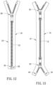
- the row of teeth 12 can be one of nylon row of teeth (as shown in FIG. 1 and FIG. 9 ), plastic steel row of teeth (as shown in FIG. 10 ) or metal row of teeth (as shown in FIG. 12 ).
- the row of teeth 12 is combined with the chain belt portion 13 on the front of the chain cloth 11, so that the row of teeth 12 is located on the front 111 of the chain cloth 11, and the back 112 of the chain cloth 11 covers the row of teeth 12 and the zipper slider 20.
- the zipper slider 20 is used to slide between the two zipper tapes 10.
- the zipper slider 20 comprises a top plate 21, a connecting device 22, a pull tab 23, a base core 24 and two side plates 25.
- the top plate 21 is integrally formed or combined with the connecting device 22 on the outside, and the front end of the pull tab 23 is combined with the connecting device 22.
- the base core 24 is an integral block protruding from the center of the inner surface of the top plate 21.
- the end of the base core 24 is provided with a first guide plate 241.
- the width of the first guide plate 241 is greater than that of the rest of the base core 24.
- a first chain tooth sliding groove 26 is formed between the first guide plate 241 and the top plate 21 on two sides of the base core 24.
- the two side plates 25 are respectively connected vertically and integrally on both sides of the inner surface of the top plate 21, and the bottom ends of the two side plates 25 are respectively provided with a second guide plate 27.
- the inner edges of the two second guide plates 27 respectively have a convex plate 271 protruding toward the center, so that a second chain tooth sliding groove 28 is formed between the convex plates 271 of the two second guide plates 27 and the top plate 21, respectively.
- the inner edge of the convex plates 271 of the second guide plates 27 and the two sides of the first guide plate 241 are spaced by a Y-shaped guide cloth seam 29.
- the top plate 21, the connecting device 22 and the pull tab 23 are formed at the front of the zipper, so that the top plate 21 leans against the rows of teeth 12 on the front of the zipper tapes 10, and no parts of the zipper slider 20 are present on the back of the two zipper tapes 10.
- the first guide plate 241 is between the inner sides of the chain belt portions 13 of the two chain cloths 10, and the first guide plate 241 and the inner edge of the convex plate 271 guide the chain belt portions 13 through the Y-shaped guide cloth seam 29, so that the convex plate 271 of the second guide plate 27 slides in the sliding space 14 within the chain belt portions 13.
- the rear end of the above-mentioned first guide plate 241 forms a tapered portion 242 protruding from the rear end of the base core 24, and both sides of the tapered portion 242 are used for guiding against the inner side of the chain cloths 11.
- the connecting device 22 and the top plate 21 of the zipper slider 20 mentioned above can be implemented in a variety of functional structures.
- the connecting device 22 can be integrally formed with the top plate 21, or the connecting device 22 can be assembled on the top plate 21, so that a perforation 221 is formed between the connecting device 22 and the top plate 21, and the front end of the pull tab 23 is implemented with a ring 231, so that the ring 231 passes through the perforation 221 and is sleeved on the connecting device 22 to pull the zipper slider 20.
- the above-mentioned connecting device 22 can also be implemented in other functional structures, for example, a locking device 50 can be implemented.
- the locking device 50 can be any structure that can be used to prevent the sliding of the zipper slider 20, such as a conventional automatic locking device (as shown in FIGS. 3-6 ), a spring-type locking device (as shown in FIGS. 19 and 20 ) or European locking device (as shown in FIGS. 21 and 22 ), etc.
- the locking device 50 is used to prevent the zipper slider 20 from sliding, and the zipper slider 20 can only be made to slide when the locking device 50 is pulled through the pull tab 23.
- the above-mentioned various locking devices 50 are specifically provided with a movable stopper pin 51 on or within the connecting device 22.
- the shape of the stopper pin 51 is not limited.
- the front end of the stopper pin 51 is a hook-shaped tip 511.
- the back end of the stopper pin 51 is provided with an elastic structure 52.
- the elastic structure 52 can be a spring or a shrapnel formed by the back end of the stopper pin 51.
- the elastic structure 52 is used to push the stopper pin 51 so that the hook-shaped tip 511 at the front end of the stopper pin 51 passes through a through hole 211 of the top plate 21, and the hook-shaped tip 511 protrudes to the inner surface of the top plate 21 to be stuck on the interlocked rows of teeth 12 to prevent the zipper slider 20 from sliding down by itself. Only when the user pulls up the stopper pin 51 with the pull tab 23, can the hook-shaped tip 511 be separated from the interlocked rows of teeth 12, so that the zipper slider 20 can slide to open the zipper.
- the anti-pinch zipper of the present invention uses the chain cloths 11 to cover the second guide plate 27 of the zipper slider 20, so that the zipper slider 20 does not have a structure that protrudes from the back of the chain cloths 11.
- the zipper slider 20 is on the outside of the garment, and the back of the two zipper tapes 10 does not interact with any parts of the zipper slider 20, and so can prevent the zipper slider 20 from being caught in the inner fabric of the garment when it moves, thereby achieving the anti-pinch function.
- the invention can be implemented into various styles of zippers. As shown in FIG. 9 , it can be implemented as a one-way closed-end zipper with a zipper slider 20; as shown in FIG. 10 , it can also be implemented as an X-shaped two-way closed-end zipper with two zipper sliders 20; or as shown in FIG. 11 , it can also be implemented as an O-shaped two-way closed-end zipper with two zipper sliders 20.
- closed-end zipper refers to a zipper whose ends of two zipper tapes 10 are never removed from the zipper slider 20. Or as shown in FIG.
- the present invention can also be implemented as a single open end zipper, that is, the lower end of one of the two zipper tapes 10 can be pulled apart by the zipper slider 20, which is usually used for the two plackets of a jacket.
- the zipper slider 20 which is usually used for the two plackets of a jacket.
- it can also be implemented as a double open end zipper, that is, a zipper in which the upper and lower ends of the two zipper tapes 10 can be separated.
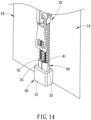
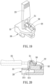
- a lower stop block 30 is provided at the proximal end of the chain belt portion 13 of one chain cloth 11, and an insert pin 40 is provided at the proximal end of the chain belt portion 13 of the other chain cloth 11.
- the lower stop block 30 and insert pin 40 can be alloy die-casting molding or plastic injection molding.
- the lower stop block 30 has a rectangular block 31, the first side of the center line 311 of the rectangular block 31 is provided with a first fixing groove 32, and the second side of the center line 311 is provided with a slot 33.
- the first fixing groove 32 and the slot 33 are grooves recessed from the upper end to the lower end of the rectangular block 31, and the first fixing groove 32 is connected to the slot 33.
- An opening 34 is provided on the back of the rectangular block 31, and the opening 34 is connected to the first fixing groove 32 and the slot 33. In this way, the chain belt portion 13 of one chain cloth 11 is folded back and passed through the opening 34, and then fixed in the first fixing groove 32, so that the lower stop block 30 is fixed to the chain belt portion 13 of the chain cloth 11 near the end.
- a convex pin 35 protrudes from the upper end of the first side of the center line 311 of the rectangular block 31, and the first fixing groove 32 is recessed into the rectangular block 31 from the upper end of the convex pin 35 to the lower end.
- the insert pin 40 is a bar corresponding to the slot 33.
- the insert pin 40 has a second fixing groove 41 recessed from its upper end to its lower end, and the second fixing groove 41 is connected to the inner side 42 of the insert pin 40.
- the insert pin 40 can be inserted into the lower stop block 30 and can also be detached in the reverse direction, so that the anti-pinch zipper can be used as a single open end zipper or a double open end zipper.
- the chain belt portion 13 of one chain cloth 11 of the double open end zipper is provided with a fixing pin 60 at the proximal end
- the chain belt portion 13 of the other chain cloth 11 is provided with an insert pin 40 at the proximal end, thereby forming a double insert pin open end zipper.
- the insert pin 40 and the fixing pin 60 are fixed to the respective chain belt portions 13, as shown in FIG. 13 and the structure on the right side of FIG. 18 .
Landscapes
- Slide Fasteners (AREA)
Claims (6)
- Reißverschluss mit Einklemmschutz, der zwei Reißverschlussbänder (10) und einen Reißverschlussschieber (20) umfasst, wobei die beiden Reißverschlussbänder (10) jeweils ein Kettenband (11) und eine Reihe von Zähnen (12) umfassen, wobei jedes Kettenband (11) eine Innenseite aufweist, die zu einer Vorderseite (111) davon umgeschlagen ist und zu einer Außenseite zurückgeschlagen ist, um einen Kettenriemenabschnitt (13) zu bilden, so dass ein Gleitraum (14) zwischen dem Kettenriemenabschnitt (13) und dem zugehörigen Kettenband (11) gebildet wird, wobei der Gleitraum (14) eine offene Seite aufweist, die der Außenseite des zugehörigen Kettengewebes (11) zugewandt ist, wobei die Reihe von Zähnen (12) mit dem Kettenriemenabschnitt (13) des zugehörigen Kettengewebes (11) kombiniert ist, so dass die Reihe von Zähnen (12) an der Vorderseite (111) des zugehörigen Kettengewebes (11) angeordnet ist;wobei der Reißverschlussschieber (20) eine obere Platte (21), eine Verbindungsvorrichtung (22), eine Zuglasche (23), einen Basiskern (24) und zwei Seitenplatten (25) umfasst; wobei die Verbindungsvorrichtung (22) außerhalb der oberen Platte (21) angeordnet ist, wobei ein vorderes Ende der Zuglasche (23) mit der Verbindungsvorrichtung (22) kombiniert ist, wobei die Mitte einer Innenfläche der oberen Platte (21) konvex mit dem Basiskern (24) versehen ist, der Basiskern (24) ein unteres Ende aufweist, das mit einer ersten Führungsplatte (241) versehen ist, wobei die Breite der ersten Führungsplatte (241) größer ist als die Breite des Basiskerns (24), wobei eine erste Kettenzahn-Gleitrille (26) zwischen der ersten Führungsplatte (241) und der oberen Platte (21) auf zwei Seiten des Basiskerns (24) ausgebildet ist, wobei die beiden Seitenplatten (25) vertikal mit zwei Seiten einer Innenfläche der oberen Platte (21) verbunden sind, wobei die beiden Seitenplatten (25) jeweils eine zweite Führungsplatte (27) an einem unteren Ende davon aufweisen, wobei eine Innenkante jeder der beiden zweiten Führungsplatten (27) jeweils eine konvexe Platte (271) aufweist, die zur Mitte hin vorsteht, eine zweite Kettenzahn-Gleitrille (28), die zwischen den konvexen Platten (271) der beiden zweiten Führungsplatten (27) und der oberen Platte (21) ausgebildet ist, wobei eine Innenkante der konvexen Platten (271) der zweiten Führungsplatten (27) und zwei Seiten der ersten Führungsplatte (241) beabstandet sind, um eine Y-förmige Führungstuchnaht (29) zu bilden;wobei der Reißverschlussschieber (20) zwischen den beiden Reißverschlussbändern (10) kombiniert ist, die Zahnreihen (12) und die Kettenbandabschnitte (13) durch die erste Kettenzahn-Gleitrille (26) und die zweite Kettenzahn-Gleitrille (28) verlaufen und die beiden Kettengewebe (11) sich durch die Y-förmige Führunggewebenaht (29) aus dem Reißverschlussschieber (20) heraus erstrecken und sich zu beiden Seiten des Reißverschlussschiebers (20) ausdehnen, so dass die Rückseite (112) der beiden Reißverschlussbänder (10) den Reißverschlussschieber (20) abdeckt;wobei die obere Platte (21), die Verbindungsvorrichtung (22) und die Zuglasche (23) an der Vorderseite (111) des Anti-Klemm-Reißverschlusses angeordnet sind, die obere Platte (21) an den Zahnreihen (12) auf der Vorderseite (111) der Kettentücher (11) anliegt und keine Teile des Reißverschlussschiebers (20) auf der Rückseite (112) der beiden Reißverschlussbänder (10) vorhanden sind; undwenn sich der Reißverschlussschieber (20) bewegt, sich die erste Führungsplatte (241) zwischen den Innenseiten der Kettenbandabschnitte (13) der beiden Kettentücher (11) befindet, die Innenkante der konvexen Platte (271) die Kettenbandabschnitte (13) durch die Y-förmige Führungstuchnaht (29) führt, und die konvexe Platte (271) jeder zweiten Führungsplatte (27) in dem Gleitraum (14) innerhalb Kettenbandabschnitte (13) gleitet,dadurch gekennzeichnet, dasseine Perforation (221) zwischen der Verbindungsvorrichtung (22) und der oberen Platte (21) ausgebildet ist; die Zuglasche (23) einen Ring (231) aufweist, der an einem vorderen Ende davon angeordnet ist, wobei der Ring (231) durch die Perforation (221) hindurchgeht und auf die Verbindungsvorrichtung (22) aufgesetzt ist,wobei die Verbindungsvorrichtung (22) eine Verriegelungsvorrichtung (50) umfasst, um zu verhindern, dass der Reißverschlussschieber (20) gleitet; und die Zuglasche (23) so angeordnet ist, dass sie die Verriegelungsvorrichtung (50) entriegelt, damit der Reißverschlussschieber (20) gleiten kann, undwobei die Verriegelungsvorrichtung (50) einen Stopperstift (51) umfasst, wobei der Stopperstift (51) eine hakenförmige Spitze (511) an seinem vorderen Ende und eine elastische Struktur (52) an seinem hinteren Ende umfasst, wobei die elastische Struktur (52) den Stopperstift (51) so drückt, dass die hakenförmige Spitze (511) in ein Durchgangsloch der oberen Platte (21) eindringt und zur Innenfläche der oberen Platte (21) vorsteht; und der Zuglaschenring (231) verwendet wird, um den Stopperstift (51) hochzuziehen.
- Reißverschluss mit Einklemmschutz- nach Anspruch 1, wobei die erste Führungsplatte (241) an ihrem hinteren Ende einen sich verjüngenden Abschnitt (242) aufweist, der vom hinteren Ende des Basiskerns (24) vorsteht, und beide Seiten des sich verjüngenden Abschnitts (242) an den Innenseiten der Kettentücher (11) anliegen.
- Reißverschluss Einklemmschutz- nach einem der vorhergehenden Ansprüche, wobei jede Zahnreihe (12) eine Zahnreihe aus Nylon (12), Kunststoffstahl (12) oder Metall (12) ist.
- Reißverschluss mit Einklemmschutz-, der zwei Reißverschlussbänder (10) und einen Reißverschlussschieber (20) umfasst, wobei die beiden Reißverschlussbänder (10) jeweils einen Kettenstoff (11) und eine Reihe von Zähnen (12) umfassen, wobei jeder Kettenstoff (11) eine Innenseite aufweist, die zu einer Vorderseite (111) davon umgeschlagen ist und zu einer Außenseite zurückgeschlagen ist, um einen Kettenriemenabschnitt (13) zu bilden, so dass ein Gleitraum (14) zwischen dem Kettenriemenabschnitt (13) und dem zugehörigen Kettenstoff (11) gebildet wird, wobei der Gleitraum (14) eine offene Seite aufweist, die der Außenseite des zugehörigen Kettengewebes (11) zugewandt ist, wobei die Reihe von Zähnen (12) mit dem Kettenriemenabschnitt (13) des zugehörigen Kettengewebes (11) kombiniert ist, so dass die Reihe von Zähnen (12) an der Vorderseite (111) des zugehörigen Kettengewebes (11) angeordnet ist;wobei der Reißverschlussschieber (20) eine obere Platte (21), eine Verbindungsvorrichtung (22), eine Zuglasche (23), einen Basiskern (24) und zwei Seitenplatten (25) umfasst; wobei die Verbindungsvorrichtung (22) außerhalb der oberen Platte (21) angeordnet ist, wobei ein vorderes Ende der Zuglasche (23) mit der Verbindungsvorrichtung (22) kombiniert ist, wobei die Mitte einer Innenfläche der oberen Platte (21) konvex mit dem Basiskern (24) versehen ist, der Basiskern (24) ein unteres Ende aufweist, das mit einer ersten Führungsplatte (241) versehen ist, wobei die Breite der ersten Führungsplatte (241) größer als die Breite des Basiskerns (24) ist, wobei eine erste Kettenzahn-Gleitrille (26) zwischen der ersten Führungsplatte (241) und der oberen Platte (21) auf zwei Seiten des Basiskerns (24) ausgebildet ist, wobei die beiden Seitenplatten (25) vertikal mit zwei Seiten einer Innenfläche der oberen Platte (21) verbunden sind, wobei die beiden Seitenplatten (25) jeweils eine zweite Führungsplatte (27) an einem unteren Ende davon aufweisen, wobei eine Innenkante jeder der beiden zweiten Führungsplatten (27) jeweils eine konvexe Platte (271) aufweist, die zur Mitte hin vorsteht eine zweite Kettenzahn-Gleitrille (28), die zwischen den konvexen Platten (271) der beiden zweiten Führungsplatten (27) und der oberen Platte (21) ausgebildet ist, wobei eine Innenkante der konvexen Platten (271) der zweiten Führungsplatten (27) und zwei Seiten der ersten Führungsplatte (241) beabstandet sind, um eine Y-förmige Führungstuchnaht (29) zu bilden;wobei der Reißverschlussschieber (20) zwischen den beiden Reißverschlussbändern (10) kombiniert ist, die Zahnreihen (12) und die Kettenbandabschnitte (13) durch die erste Kettenzahn-Gleitrille (26) und die zweite Kettenzahn-Gleitrille (28) verlaufen und die beiden Kettengewebe (11) sich durch die Y-förmige Führunggewebenaht (29) aus dem Reißverschlussschieber (20) heraus erstrecken und sich zu beiden Seiten des Reißverschlussschiebers (20) ausdehnen, so dass die Rückseite (112) der beiden Reißverschlussbänder (10) den Reißverschlussschieber (20) abdeckt;die obere Platte (21), die Verbindungsvorrichtung (22) und die Zuglasche (23) an der Vorderseite (111) des Anti-Klemm-Reißverschlusses angeordnet sind, die obere Platte (21) an den Zahnreihen (12) auf der Vorderseite (111) der Kettentücher (11) anliegt und keine Teile des Reißverschlussschiebers (20) auf der Rückseite (112) der beiden Reißverschlussbänder (10) vorhanden sind; undwenn sich der Reißverschlussschieber (20) bewegt, sich die erste Führungsplatte (241) zwischen den Innenseiten der Kettenbandabschnitte (13) der beiden Kettentücher (11) befindet, die Innenkante der konvexen Platte (271) die Kettenbandabschnitte (13) durch die Y-förmige Führungstuchnaht (29) führt, und die konvexe Platte (271) jeder zweiten Führungsplatte (27) in dem Gleitraum (14) innerhalb der Kettenbandabschnitte (13) gleitet,dadurch gekennzeichnet, dassdie beiden Reißverschlussbänder (10) so ausgeführt sind, dass der Einklemmschutz-Reißverschluss ein Einweg- oder Zweiweg-Reißverschluss mit geschlossenem Ende, ein Reißverschluss mit offenem Ende oder ein Reißverschluss mit doppeltem offenen Ende ist,wobei die zwei Reißverschlußbänder (10) für einen einfachen Reißverschluß mit offenem Ende oder einen doppelten Reißverschluß mit offenem Ende implementiert sind, der Kettengurtabschnitt (13) eines der zwei Kettentücher (11) mit einem unteren Anschlagblock (30) an einem proximalen Ende versehen ist, und der Kettengurtabschnitt (13) des anderen Kettenbandes (11) mit einem Einsatzstift (40) an einem proximalen Ende versehen ist, wobei:der untere Anschlagblock (30) einen rechteckigen Block (31) umfasst, wobei der rechteckige Block (31) eine erste Befestigungsnut (32), die sich auf einer ersten Seite einer Mittellinie (311) desselben befindet, und einen Schlitz (33), der sich auf einer zweiten Seite der Mittellinie (311) befindet, umfasst; die erste Befestigungsnut (32) und der Schlitz (33) Nuten sind, die von einem oberen Ende zu einem gegenüberliegenden unteren Ende des rechteckigen Blocks (31) ausgespart sind, und die erste Befestigungsnut (32) mit dem Schlitz (33) verbunden ist; der rechteckige Block (31) eine Öffnung (34) auf seiner Rückseite aufweist, wobei die Öffnung (34) die erste Befestigungsnut (32) und den Schlitz (33) verbindet; der Kettenriemenabschnitt (13) des Kettenbands (11), der dem unteren Anschlagblock (30) entspricht, zurückgefaltet und durch die Öffnung (34) geführt und dann in der ersten Befestigungsnut (32) befestigt wird; undder Einsatzstift (40) ein Stab ist, der dem Schlitz (33) entspricht, wobei der Einsatzstift (40) eine zweite Befestigungsnut (41) aufweist, die von einem oberen Ende desselben zu einem gegenüberliegenden unteren Ende desselben vertieft ist, wobei die zweite Befestigungsnut (41) mit einer Innenseite des Einsatzstifts (40) verbunden ist; der Kettenbandabschnitt (13) des Kettenbands (11), der dem Einsatzstift (40) entspricht, zurückgefaltet und in der zweiten Befestigungsnut (41) befestigt ist.
- Reißverschluss mit Einklemmschutz nach Anspruch 4, wobei das obere Ende der ersten Seite der Mittellinie (311) des rechteckigen Blocks (31) ein vorstehender konvexer Stift (35) ist und die erste Befestigungsrille (32) in den rechteckigen Block (31) vom oberen Ende des konvexen Stifts (35) zum unteren Ende hin eingelassen ist.
- Reißverschluss mit Einklemmschutz nach einem der Ansprüche 4-5, wobei die beiden Reißverschlussbänder (10) für einen Doppelreißverschluss mit offenem Ende eingesetzt werden, ein Befestigungsstift (60) an einem proximalen Ende des Kettenbandabschnitts (13) eines der beiden Kettentücher (11) vorgesehen ist und ein Einsatzstift (40) an einem proximalen Ende des Kettenbandabschnitts (13) des anderen Kettenbands (11) vorgesehen ist.
Applications Claiming Priority (2)
| Application Number | Priority Date | Filing Date | Title |
|---|---|---|---|
| TW110141644A TWI784787B (zh) | 2021-11-09 | 2021-11-09 | 防夾拉鏈 |
| TW110213193U TWM624460U (zh) | 2021-11-09 | 2021-11-09 | 防夾拉鏈 |
Publications (3)
| Publication Number | Publication Date |
|---|---|
| EP4176754A1 EP4176754A1 (de) | 2023-05-10 |
| EP4176754C0 EP4176754C0 (de) | 2025-04-23 |
| EP4176754B1 true EP4176754B1 (de) | 2025-04-23 |
Family
ID=85785411
Family Applications (1)
| Application Number | Title | Priority Date | Filing Date |
|---|---|---|---|
| EP21215949.5A Active EP4176754B1 (de) | 2021-11-09 | 2021-12-20 | Reissverschluss mit einklemmschutz |
Country Status (2)
| Country | Link |
|---|---|
| US (1) | US11653725B1 (de) |
| EP (1) | EP4176754B1 (de) |
Families Citing this family (1)
| Publication number | Priority date | Publication date | Assignee | Title |
|---|---|---|---|---|
| USD1026730S1 (en) * | 2022-10-17 | 2024-05-14 | Ideal Fastener (Guangdong) Industries Ltd. | Slider body |
Family Cites Families (39)
| Publication number | Priority date | Publication date | Assignee | Title |
|---|---|---|---|---|
| US2510736A (en) * | 1946-03-30 | 1950-06-06 | Joseph J Helby | Slider for separable slide fasteners |
| US2824352A (en) * | 1954-06-07 | 1958-02-25 | Knit Wear Patents Inc | Slidable fastener |
| US2855652A (en) * | 1955-11-25 | 1958-10-14 | Ralph E Jones | Zipper slider |
| US2933792A (en) * | 1957-11-12 | 1960-04-26 | Eric W Malmborg | Snag-proof slide fastener guard |
| US2905996A (en) * | 1958-05-19 | 1959-09-29 | Ralph E Jones | Slide fastener |
| US3046627A (en) * | 1960-05-09 | 1962-07-31 | Louis H Morin | Separator for invisible separable fastener stringers |
| DE2247788C3 (de) | 1972-09-29 | 1980-05-14 | Akzo Gmbh, 5600 Wuppertal | Verfahren zur Herstellung von Terephthalsäuredichlorid |
| US4261082A (en) * | 1979-08-03 | 1981-04-14 | Minoru Kamiya | Slide fastener for preventing jamming of foreign matter |
| JPS60193404A (ja) * | 1984-03-15 | 1985-10-01 | ワイケイケイ株式会社 | 開離嵌插具付きスライドフアスナ− |
| US4819308A (en) * | 1988-03-14 | 1989-04-11 | Baroky Julian K | Zipper guard |
| US5131120A (en) * | 1991-12-23 | 1992-07-21 | Yoshida Kogyo K.K. | Separable bottom end assembly for slide fastener |
| JPH0838219A (ja) * | 1994-07-29 | 1996-02-13 | Ykk Kk | スライドファスナーの開離嵌挿具 |
| JP2000262309A (ja) * | 1999-03-17 | 2000-09-26 | Ykk Corp | スライドファスナー用スライダー |
| US6510590B1 (en) * | 2001-09-06 | 2003-01-28 | Hsin-Heng Lin | Slip proof device for a necktie having a zipper thereon |
| JP3733327B2 (ja) * | 2001-12-20 | 2006-01-11 | Ykk株式会社 | 隠しスライドファスナーの開離嵌挿具 |
| US6588072B1 (en) * | 2001-12-31 | 2003-07-08 | Yu-Pau Lin | Zipper slide |
| US6701584B2 (en) * | 2002-03-21 | 2004-03-09 | The Coleman Company, Inc. | Zipper guard |
| US6928703B2 (en) * | 2002-03-25 | 2005-08-16 | Robin Petravic | Sealed slider adjustment mechanism |
| JP2003334108A (ja) * | 2002-05-20 | 2003-11-25 | Ykk Corp | 開離嵌挿具付きスライドファスナー |
| JP2004024740A (ja) | 2002-06-28 | 2004-01-29 | Phoenix:Kk | スライドファスナー |
| JP4152216B2 (ja) * | 2003-02-19 | 2008-09-17 | Ykk株式会社 | スライドファスナー用開離嵌挿具 |
| JP4072953B2 (ja) * | 2003-03-20 | 2008-04-09 | Ykk株式会社 | 開離嵌挿具付きスライドファスナー |
| JP2004283300A (ja) * | 2003-03-20 | 2004-10-14 | Ykk Corp | 開離嵌挿具付きスライドファスナー |
| US7036191B2 (en) * | 2003-04-21 | 2006-05-02 | Chang-Wen Tsaur | Lower stop of zipper |
| JP4307413B2 (ja) * | 2005-06-20 | 2009-08-05 | Ykk株式会社 | スライドファスナー用開離嵌挿具 |
| US20070071367A1 (en) * | 2005-09-27 | 2007-03-29 | Buchman James E | Reclosable package and method |
| JP4906637B2 (ja) | 2007-08-20 | 2012-03-28 | Ykk株式会社 | 開離嵌挿具付隠しスライドファスナー用スライダー |
| AR078692A1 (es) | 2009-01-30 | 2011-11-30 | Columbia Sportswear Na Inc | Cierre de cremallera resistente al enganche |
| WO2011016123A1 (ja) * | 2009-08-06 | 2011-02-10 | Ykk株式会社 | スライドファスナー |
| EP2517595B1 (de) * | 2009-12-25 | 2015-12-23 | YKK Corporation | Reisverschluss mit umgekehrtem öffnungsmechanismus |
| CN103813732B (zh) * | 2011-09-21 | 2016-03-23 | Ykk株式会社 | 拉链及拉链的制造方法 |
| WO2014033926A1 (ja) | 2012-08-31 | 2014-03-06 | Ykk株式会社 | スライドファスナーのスライダーカバー及びスライダーカバー付きスライドファスナー |
| CN104106888B (zh) | 2014-07-15 | 2017-02-08 | 泉州市中研智能机电研究院有限公司 | 防夹拉链头 |
| JP6225266B2 (ja) * | 2014-09-01 | 2017-11-01 | Ykk株式会社 | スライドファスナーのスライダーカバー |
| CN106714611B (zh) * | 2014-09-19 | 2019-09-13 | Ykk株式会社 | 拉链用拉头 |
| KR200482266Y1 (ko) | 2015-04-29 | 2017-01-05 | 이강산 | 옷의 끼임이 방지되도록 유입방지구가 구비된 지퍼용 슬라이더 |
| EP3549477B1 (de) * | 2016-11-30 | 2023-03-29 | YKK Corporation | Gleitelement für reissverschluss |
| TW202102159A (zh) * | 2019-07-11 | 2021-01-16 | 墾青工業股份有限公司 | 鈕扣拉鏈 |
| CN211298642U (zh) | 2019-11-20 | 2020-08-21 | 重庆森威服饰集团有限公司 | 一种防夹伤的拉链结构 |
-
2021
- 2021-12-16 US US17/552,671 patent/US11653725B1/en active Active
- 2021-12-20 EP EP21215949.5A patent/EP4176754B1/de active Active
Also Published As
| Publication number | Publication date |
|---|---|
| US20230145192A1 (en) | 2023-05-11 |
| US11653725B1 (en) | 2023-05-23 |
| EP4176754C0 (de) | 2025-04-23 |
| EP4176754A1 (de) | 2023-05-10 |
Similar Documents
| Publication | Publication Date | Title |
|---|---|---|
| KR100870595B1 (ko) | 슬라이드 파스너의 역개방 개방 격리용 끼움 부재 | |
| TWI563935B (zh) | Zipper chain, chain and zipper | |
| EP1614364B1 (de) | Verdeckter Reissverschluss | |
| CN107495547B (zh) | 方便双头脱开的拉链 | |
| TW201014542A (en) | Slide fastener | |
| TWI433653B (zh) | zipper | |
| JP2000262309A (ja) | スライドファスナー用スライダー | |
| US4819308A (en) | Zipper guard | |
| CN102858199B (zh) | 隐形拉链 | |
| TWI487491B (zh) | zipper | |
| EP4176754B1 (de) | Reissverschluss mit einklemmschutz | |
| EP4275542B1 (de) | Untere anschlagvorrichtung eines reissverschlusses mit einklemmschutz und ihre montagestruktur | |
| CN218219383U (zh) | 防夹拉链的下止装置及其组装结构 | |
| CN116348010B (zh) | 双开尾拉链用分离嵌插件 | |
| CN216875279U (zh) | 防夹拉链 | |
| US11877629B1 (en) | Bottom stop device of double-open end zipper and assembly structure thereof | |
| EP1300094A1 (de) | Reissverschluss | |
| TW200416007A (en) | Slide fastener | |
| CN215775983U (zh) | 一种拉链 | |
| US2792610A (en) | Slide fasteners | |
| CN216568441U (zh) | 带有拉链的运动服装 | |
| TWM624460U (zh) | 防夾拉鏈 | |
| EP1300093B1 (de) | Reißverschluss | |
| CN220898117U (zh) | 拉绳可分合的拉片结构及对应的拉头结构和拉链 | |
| CN211483196U (zh) | 一种隐形拉链及一种拉头 |
Legal Events
| Date | Code | Title | Description |
|---|---|---|---|
| PUAI | Public reference made under article 153(3) epc to a published international application that has entered the european phase |
Free format text: ORIGINAL CODE: 0009012 |
|
| STAA | Information on the status of an ep patent application or granted ep patent |
Free format text: STATUS: THE APPLICATION HAS BEEN PUBLISHED |
|
| AK | Designated contracting states |
Kind code of ref document: A1 Designated state(s): AL AT BE BG CH CY CZ DE DK EE ES FI FR GB GR HR HU IE IS IT LI LT LU LV MC MK MT NL NO PL PT RO RS SE SI SK SM TR |
|
| STAA | Information on the status of an ep patent application or granted ep patent |
Free format text: STATUS: REQUEST FOR EXAMINATION WAS MADE |
|
| 17P | Request for examination filed |
Effective date: 20231010 |
|
| RBV | Designated contracting states (corrected) |
Designated state(s): AL AT BE BG CH CY CZ DE DK EE ES FI FR GB GR HR HU IE IS IT LI LT LU LV MC MK MT NL NO PL PT RO RS SE SI SK SM TR |
|
| GRAP | Despatch of communication of intention to grant a patent |
Free format text: ORIGINAL CODE: EPIDOSNIGR1 |
|
| STAA | Information on the status of an ep patent application or granted ep patent |
Free format text: STATUS: GRANT OF PATENT IS INTENDED |
|
| INTG | Intention to grant announced |
Effective date: 20241220 |
|
| GRAS | Grant fee paid |
Free format text: ORIGINAL CODE: EPIDOSNIGR3 |
|
| GRAA | (expected) grant |
Free format text: ORIGINAL CODE: 0009210 |
|
| STAA | Information on the status of an ep patent application or granted ep patent |
Free format text: STATUS: THE PATENT HAS BEEN GRANTED |
|
| AK | Designated contracting states |
Kind code of ref document: B1 Designated state(s): AL AT BE BG CH CY CZ DE DK EE ES FI FR GB GR HR HU IE IS IT LI LT LU LV MC MK MT NL NO PL PT RO RS SE SI SK SM TR |
|
| REG | Reference to a national code |
Ref country code: GB Ref legal event code: FG4D |
|
| REG | Reference to a national code |
Ref country code: CH Ref legal event code: EP |
|
| REG | Reference to a national code |
Ref country code: DE Ref legal event code: R096 Ref document number: 602021029542 Country of ref document: DE |
|
| REG | Reference to a national code |
Ref country code: IE Ref legal event code: FG4D |
|
| U01 | Request for unitary effect filed |
Effective date: 20250507 |
|
| U07 | Unitary effect registered |
Designated state(s): AT BE BG DE DK EE FI FR IT LT LU LV MT NL PT RO SE SI Effective date: 20250514 |
|
| PG25 | Lapsed in a contracting state [announced via postgrant information from national office to epo] |
Ref country code: ES Free format text: LAPSE BECAUSE OF FAILURE TO SUBMIT A TRANSLATION OF THE DESCRIPTION OR TO PAY THE FEE WITHIN THE PRESCRIBED TIME-LIMIT Effective date: 20250423 |
|
| PG25 | Lapsed in a contracting state [announced via postgrant information from national office to epo] |
Ref country code: NO Free format text: LAPSE BECAUSE OF FAILURE TO SUBMIT A TRANSLATION OF THE DESCRIPTION OR TO PAY THE FEE WITHIN THE PRESCRIBED TIME-LIMIT Effective date: 20250723 Ref country code: GR Free format text: LAPSE BECAUSE OF FAILURE TO SUBMIT A TRANSLATION OF THE DESCRIPTION OR TO PAY THE FEE WITHIN THE PRESCRIBED TIME-LIMIT Effective date: 20250724 |
|
| PG25 | Lapsed in a contracting state [announced via postgrant information from national office to epo] |
Ref country code: PL Free format text: LAPSE BECAUSE OF FAILURE TO SUBMIT A TRANSLATION OF THE DESCRIPTION OR TO PAY THE FEE WITHIN THE PRESCRIBED TIME-LIMIT Effective date: 20250423 |
|
| PG25 | Lapsed in a contracting state [announced via postgrant information from national office to epo] |
Ref country code: HR Free format text: LAPSE BECAUSE OF FAILURE TO SUBMIT A TRANSLATION OF THE DESCRIPTION OR TO PAY THE FEE WITHIN THE PRESCRIBED TIME-LIMIT Effective date: 20250423 |
|
| PG25 | Lapsed in a contracting state [announced via postgrant information from national office to epo] |
Ref country code: RS Free format text: LAPSE BECAUSE OF FAILURE TO SUBMIT A TRANSLATION OF THE DESCRIPTION OR TO PAY THE FEE WITHIN THE PRESCRIBED TIME-LIMIT Effective date: 20250723 |
|
| PG25 | Lapsed in a contracting state [announced via postgrant information from national office to epo] |
Ref country code: IS Free format text: LAPSE BECAUSE OF FAILURE TO SUBMIT A TRANSLATION OF THE DESCRIPTION OR TO PAY THE FEE WITHIN THE PRESCRIBED TIME-LIMIT Effective date: 20250823 |
|
| PGFP | Annual fee paid to national office [announced via postgrant information from national office to epo] |
Ref country code: GB Payment date: 20251219 Year of fee payment: 5 |
|
| PG25 | Lapsed in a contracting state [announced via postgrant information from national office to epo] |
Ref country code: SM Free format text: LAPSE BECAUSE OF FAILURE TO SUBMIT A TRANSLATION OF THE DESCRIPTION OR TO PAY THE FEE WITHIN THE PRESCRIBED TIME-LIMIT Effective date: 20250423 |
|
| PGFP | Annual fee paid to national office [announced via postgrant information from national office to epo] |
Ref country code: TR Payment date: 20251216 Year of fee payment: 5 |
|
| PG25 | Lapsed in a contracting state [announced via postgrant information from national office to epo] |
Ref country code: CZ Free format text: LAPSE BECAUSE OF FAILURE TO SUBMIT A TRANSLATION OF THE DESCRIPTION OR TO PAY THE FEE WITHIN THE PRESCRIBED TIME-LIMIT Effective date: 20250423 |
|
| PG25 | Lapsed in a contracting state [announced via postgrant information from national office to epo] |
Ref country code: SK Free format text: LAPSE BECAUSE OF FAILURE TO SUBMIT A TRANSLATION OF THE DESCRIPTION OR TO PAY THE FEE WITHIN THE PRESCRIBED TIME-LIMIT Effective date: 20250423 |
|
| U20 | Renewal fee for the european patent with unitary effect paid |
Year of fee payment: 5 Effective date: 20251231 |