EP4176176B1 - Schaltmittel von arbeitsfluid - Google Patents
Schaltmittel von arbeitsfluid Download PDFInfo
- Publication number
- EP4176176B1 EP4176176B1 EP21737539.3A EP21737539A EP4176176B1 EP 4176176 B1 EP4176176 B1 EP 4176176B1 EP 21737539 A EP21737539 A EP 21737539A EP 4176176 B1 EP4176176 B1 EP 4176176B1
- Authority
- EP
- European Patent Office
- Prior art keywords
- annular surface
- annular
- switching
- switching part
- working fluid
- Prior art date
- Legal status (The legal status is an assumption and is not a legal conclusion. Google has not performed a legal analysis and makes no representation as to the accuracy of the status listed.)
- Active
Links
Images
Classifications
-
- F—MECHANICAL ENGINEERING; LIGHTING; HEATING; WEAPONS; BLASTING
- F16—ENGINEERING ELEMENTS AND UNITS; GENERAL MEASURES FOR PRODUCING AND MAINTAINING EFFECTIVE FUNCTIONING OF MACHINES OR INSTALLATIONS; THERMAL INSULATION IN GENERAL
- F16K—VALVES; TAPS; COCKS; ACTUATING-FLOATS; DEVICES FOR VENTING OR AERATING
- F16K31/00—Actuating devices; Operating means; Releasing devices
- F16K31/12—Actuating devices; Operating means; Releasing devices actuated by fluid
- F16K31/122—Actuating devices; Operating means; Releasing devices actuated by fluid the fluid acting on a piston
-
- F—MECHANICAL ENGINEERING; LIGHTING; HEATING; WEAPONS; BLASTING
- F15—FLUID-PRESSURE ACTUATORS; HYDRAULICS OR PNEUMATICS IN GENERAL
- F15B—SYSTEMS ACTING BY MEANS OF FLUIDS IN GENERAL; FLUID-PRESSURE ACTUATORS, e.g. SERVOMOTORS; DETAILS OF FLUID-PRESSURE SYSTEMS, NOT OTHERWISE PROVIDED FOR
- F15B13/00—Details of servomotor systems ; Valves for servomotor systems
- F15B13/02—Fluid distribution or supply devices characterised by their adaptation to the control of servomotors
- F15B13/04—Fluid distribution or supply devices characterised by their adaptation to the control of servomotors for use with a single servomotor
- F15B13/0401—Valve members; Fluid interconnections therefor
- F15B13/0402—Valve members; Fluid interconnections therefor for linearly sliding valves, e.g. spool valves
-
- F—MECHANICAL ENGINEERING; LIGHTING; HEATING; WEAPONS; BLASTING
- F15—FLUID-PRESSURE ACTUATORS; HYDRAULICS OR PNEUMATICS IN GENERAL
- F15B—SYSTEMS ACTING BY MEANS OF FLUIDS IN GENERAL; FLUID-PRESSURE ACTUATORS, e.g. SERVOMOTORS; DETAILS OF FLUID-PRESSURE SYSTEMS, NOT OTHERWISE PROVIDED FOR
- F15B13/00—Details of servomotor systems ; Valves for servomotor systems
- F15B13/02—Fluid distribution or supply devices characterised by their adaptation to the control of servomotors
- F15B13/04—Fluid distribution or supply devices characterised by their adaptation to the control of servomotors for use with a single servomotor
- F15B13/042—Fluid distribution or supply devices characterised by their adaptation to the control of servomotors for use with a single servomotor operated by fluid pressure
-
- F—MECHANICAL ENGINEERING; LIGHTING; HEATING; WEAPONS; BLASTING
- F15—FLUID-PRESSURE ACTUATORS; HYDRAULICS OR PNEUMATICS IN GENERAL
- F15B—SYSTEMS ACTING BY MEANS OF FLUIDS IN GENERAL; FLUID-PRESSURE ACTUATORS, e.g. SERVOMOTORS; DETAILS OF FLUID-PRESSURE SYSTEMS, NOT OTHERWISE PROVIDED FOR
- F15B20/00—Safety arrangements for fluid actuator systems; Applications of safety devices in fluid actuator systems; Emergency measures for fluid actuator systems
-
- F—MECHANICAL ENGINEERING; LIGHTING; HEATING; WEAPONS; BLASTING
- F16—ENGINEERING ELEMENTS AND UNITS; GENERAL MEASURES FOR PRODUCING AND MAINTAINING EFFECTIVE FUNCTIONING OF MACHINES OR INSTALLATIONS; THERMAL INSULATION IN GENERAL
- F16K—VALVES; TAPS; COCKS; ACTUATING-FLOATS; DEVICES FOR VENTING OR AERATING
- F16K11/00—Multiple-way valves, e.g. mixing valves; Pipe fittings incorporating such valves
- F16K11/02—Multiple-way valves, e.g. mixing valves; Pipe fittings incorporating such valves with all movable sealing faces moving as one unit
- F16K11/06—Multiple-way valves, e.g. mixing valves; Pipe fittings incorporating such valves with all movable sealing faces moving as one unit comprising only sliding valves, i.e. sliding closure elements
- F16K11/065—Multiple-way valves, e.g. mixing valves; Pipe fittings incorporating such valves with all movable sealing faces moving as one unit comprising only sliding valves, i.e. sliding closure elements with linearly sliding closure members
- F16K11/07—Multiple-way valves, e.g. mixing valves; Pipe fittings incorporating such valves with all movable sealing faces moving as one unit comprising only sliding valves, i.e. sliding closure elements with linearly sliding closure members with cylindrical slides
- F16K11/0716—Multiple-way valves, e.g. mixing valves; Pipe fittings incorporating such valves with all movable sealing faces moving as one unit comprising only sliding valves, i.e. sliding closure elements with linearly sliding closure members with cylindrical slides with fluid passages through the valve member
-
- F—MECHANICAL ENGINEERING; LIGHTING; HEATING; WEAPONS; BLASTING
- F16—ENGINEERING ELEMENTS AND UNITS; GENERAL MEASURES FOR PRODUCING AND MAINTAINING EFFECTIVE FUNCTIONING OF MACHINES OR INSTALLATIONS; THERMAL INSULATION IN GENERAL
- F16K—VALVES; TAPS; COCKS; ACTUATING-FLOATS; DEVICES FOR VENTING OR AERATING
- F16K31/00—Actuating devices; Operating means; Releasing devices
- F16K31/12—Actuating devices; Operating means; Releasing devices actuated by fluid
- F16K31/36—Actuating devices; Operating means; Releasing devices actuated by fluid in which fluid from the circuit is constantly supplied to the fluid motor
- F16K31/363—Actuating devices; Operating means; Releasing devices actuated by fluid in which fluid from the circuit is constantly supplied to the fluid motor the fluid acting on a piston
-
- B—PERFORMING OPERATIONS; TRANSPORTING
- B25—HAND TOOLS; PORTABLE POWER-DRIVEN TOOLS; MANIPULATORS
- B25D—PERCUSSIVE TOOLS
- B25D2209/00—Details of portable percussive tools with fluid-pressure drive, i.e. driven directly by fluids, e.g. having several percussive tool bits operated simultaneously
- B25D2209/007—Details of portable percussive tools with fluid-pressure drive, i.e. driven directly by fluids, e.g. having several percussive tool bits operated simultaneously having a tubular-slide valve, which is not coaxial with the piston
-
- B—PERFORMING OPERATIONS; TRANSPORTING
- B25—HAND TOOLS; PORTABLE POWER-DRIVEN TOOLS; MANIPULATORS
- B25D—PERCUSSIVE TOOLS
- B25D9/00—Portable percussive tools with fluid-pressure drive, i.e. driven directly by fluids, e.g. having several percussive tool bits operated simultaneously
- B25D9/14—Control devices for the reciprocating piston
- B25D9/16—Valve arrangements therefor
- B25D9/20—Valve arrangements therefor involving a tubular-type slide valve
-
- E—FIXED CONSTRUCTIONS
- E02—HYDRAULIC ENGINEERING; FOUNDATIONS; SOIL SHIFTING
- E02F—DREDGING; SOIL-SHIFTING
- E02F3/00—Dredgers; Soil-shifting machines
- E02F3/04—Dredgers; Soil-shifting machines mechanically-driven
- E02F3/28—Dredgers; Soil-shifting machines mechanically-driven with digging tools mounted on a dipper- or bucket-arm, i.e. there is either one arm or a pair of arms, e.g. dippers, buckets
- E02F3/36—Component parts
- E02F3/3604—Devices to connect tools to arms, booms or the like
- E02F3/3609—Devices to connect tools to arms, booms or the like of the quick acting type, e.g. controlled from the operator seat
- E02F3/3654—Devices to connect tools to arms, booms or the like of the quick acting type, e.g. controlled from the operator seat with energy coupler, e.g. coupler for hydraulic or electric lines, to provide energy to drive(s) mounted on the tool
-
- E—FIXED CONSTRUCTIONS
- E02—HYDRAULIC ENGINEERING; FOUNDATIONS; SOIL SHIFTING
- E02F—DREDGING; SOIL-SHIFTING
- E02F3/00—Dredgers; Soil-shifting machines
- E02F3/04—Dredgers; Soil-shifting machines mechanically-driven
- E02F3/96—Dredgers; Soil-shifting machines mechanically-driven with arrangements for alternate or simultaneous use of different digging elements
- E02F3/966—Dredgers; Soil-shifting machines mechanically-driven with arrangements for alternate or simultaneous use of different digging elements of hammer-type tools
-
- E—FIXED CONSTRUCTIONS
- E02—HYDRAULIC ENGINEERING; FOUNDATIONS; SOIL SHIFTING
- E02F—DREDGING; SOIL-SHIFTING
- E02F9/00—Component parts of dredgers or soil-shifting machines, not restricted to one of the kinds covered by groups E02F3/00 - E02F7/00
- E02F9/20—Drives; Control devices
- E02F9/22—Hydraulic or pneumatic drives
- E02F9/2264—Arrangements or adaptations of elements for hydraulic drives
- E02F9/2267—Valves or distributors
-
- F—MECHANICAL ENGINEERING; LIGHTING; HEATING; WEAPONS; BLASTING
- F15—FLUID-PRESSURE ACTUATORS; HYDRAULICS OR PNEUMATICS IN GENERAL
- F15B—SYSTEMS ACTING BY MEANS OF FLUIDS IN GENERAL; FLUID-PRESSURE ACTUATORS, e.g. SERVOMOTORS; DETAILS OF FLUID-PRESSURE SYSTEMS, NOT OTHERWISE PROVIDED FOR
- F15B13/00—Details of servomotor systems ; Valves for servomotor systems
- F15B13/02—Fluid distribution or supply devices characterised by their adaptation to the control of servomotors
- F15B13/04—Fluid distribution or supply devices characterised by their adaptation to the control of servomotors for use with a single servomotor
- F15B13/0401—Valve members; Fluid interconnections therefor
- F15B2013/041—Valve members; Fluid interconnections therefor with two positions
-
- F—MECHANICAL ENGINEERING; LIGHTING; HEATING; WEAPONS; BLASTING
- F15—FLUID-PRESSURE ACTUATORS; HYDRAULICS OR PNEUMATICS IN GENERAL
- F15B—SYSTEMS ACTING BY MEANS OF FLUIDS IN GENERAL; FLUID-PRESSURE ACTUATORS, e.g. SERVOMOTORS; DETAILS OF FLUID-PRESSURE SYSTEMS, NOT OTHERWISE PROVIDED FOR
- F15B2211/00—Circuits for servomotor systems
- F15B2211/80—Other types of control related to particular problems or conditions
- F15B2211/86—Control during or prevention of abnormal conditions
- F15B2211/8643—Control during or prevention of abnormal conditions the abnormal condition being a human failure
-
- F—MECHANICAL ENGINEERING; LIGHTING; HEATING; WEAPONS; BLASTING
- F15—FLUID-PRESSURE ACTUATORS; HYDRAULICS OR PNEUMATICS IN GENERAL
- F15B—SYSTEMS ACTING BY MEANS OF FLUIDS IN GENERAL; FLUID-PRESSURE ACTUATORS, e.g. SERVOMOTORS; DETAILS OF FLUID-PRESSURE SYSTEMS, NOT OTHERWISE PROVIDED FOR
- F15B2211/00—Circuits for servomotor systems
- F15B2211/80—Other types of control related to particular problems or conditions
- F15B2211/865—Prevention of failures
Definitions
- the invention relates to a switching means for polarizing the supply and return of a working fluid for consumers independently of a supply polarity.
- the switching device for polarizing the supply and return of a working medium for consumers is known, regardless of the supply polarity.
- the switching device has a connection part, a valve body with one or more connections for an inlet and outlet of the working medium.
- Hydraulic consumers such as hydraulic impact mechanisms
- Hydraulic consumers may have high-pressure connections for working fluid and connections for returning the same with the same connecting means such as similar threaded parts and the like.
- the connections for supply and return of working fluid can become disadvantageously confused.
- Such impact mechanisms and consumers usually have a maximum permissible return pressure or maximum pressure in the area of the discharge of the working medium of 8 bar, so that incorrect connections with high pressure in this return area can lead to malfunctions in the operation or damage to a consumer.
- a switching means formed with a connection part comprising feed poles for producing the feed polarity, a valve body with one or more connections each for an inlet and a discharge of the working fluid with a tubular switching part which can be axially displaced within limits in the valve body with radial bores in two axially spaced planes with a base part and a top part, each forming the displacement limits for the switching part, wherein in the area of the inner surface of the valve body and the outer surface of the switching part a first, second, third, fourth and fifth cooperating annular space are formed for the respective guidance of working fluid and a second, third, fifth and seventh ring surfaces which can be acted upon by working fluid and on the switching part a first, fourth and sixth ring surface which can be acted upon towards the base part and have certain size relationships with the proviso that There is a permanent fluid connection between the first annular space and the third annular space.
- a one-sided limitation according to the invention of the size relationships of the ring surfaces of the switching part that can be exposed to high-pressure fluid towards the top part and the base part has the advantage that the intensity of a hydraulic switching of a required polarity of the supply for a consumer is increased as the inequality of the values increases.
- a so-called switching shock when creating a required supply polarity for a consumer can be set by selecting the size relationships of the axial ring surfaces of the switching part.
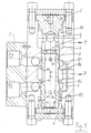
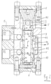
- the graphic representations show in principle variants with different supply polarity of a switching device according to the invention arranged in front of a consumer.
- connection E2 of connection part 1 ( Fig.1 )
- connection part 1 ( Fig.1 )
- connection part 2 when a switching part 3 is positioned on the base part 4, there is a connection to the annular space R2.
- This annular space 2 has a coaxial passage between the switching part 3 and the valve body 2 to the annular space R4 and thus to the high-pressure inlet of a consumer
- a discharge T of working fluid from the consumer is connected to an annular space R5 in the valve body 2.
- a top part 5 with an axial blind hole S and inlet holes L protrudes through the hole wall into the annular space R5, which form cavities that guide the hydraulic fluid into a tubular switching part 3.
- the switching part 3 positioned on the base part 4 has radial holes B1 and B2 in two axially spaced planes, of which only the hole B1 has a connection to the annular space R1 and further to the connection E1 for a return of the working fluid at low pressure.
- Working fluid with low pressure in a discharge T from the consumer can be led into an annular space R5 and further through inlet holes L into an axial blind hole S of a top part 5 and consequently into a tubular switching part 3.
- the bores B2 in the adjacent switching part 3 provide a connection to the annular space R2 and subsequently to connection E2 for the return of the working fluid from the consumer.
- Positioning of the switching part 3 on the base part 4 is justified by subjecting the ring surfaces A1 minus the ring surface A2 to high pressure fluid P while taking into account the ring surfaces (A4 + A6) minus the ring surfaces (A3 + A5 + A7) with low pressure from the discharge fluid.
- Positioning of the switching part 3 on the top part is justified by subjecting the ring surfaces (A2 + A3) minus the ring surface A1 to high pressure fluid P while taking into account the ring surfaces (A5 + A7) minus the ring surfaces (A6 + A4) with low pressure from the discharge fluid.
Landscapes
- Engineering & Computer Science (AREA)
- General Engineering & Computer Science (AREA)
- Mechanical Engineering (AREA)
- Physics & Mathematics (AREA)
- Fluid Mechanics (AREA)
- Chemical & Material Sciences (AREA)
- Analytical Chemistry (AREA)
- Multiple-Way Valves (AREA)
- Servomotors (AREA)
Description
- Die Erfindung bezieht sich auf ein Schaltmittel zur Polung der Zu- und Rückführung eines Arbeitsfluids für Verbraucher unabhängig von einer Anspeisungspolarität.
- Aus der
WO 2013/037356 A1 ist ein Schaltmittel zur Polung der Zu- und Rückführung eines Arbeitsmittels für Verbraucher unabhängig von einer Anspeisungspolarität bekannt. Das Schaltmittel weist einen Anschlussteil, einen Ventilkörper mit einem oder mehreren Anschlüssen für einen Zulauf und einer Abführung des Arbeitsmittels auf. - Hydraulische Verbraucher, wie beispielsweise hydraulische Schlagwerke, weisen gegebenenfalls Hochdruckanschlüsse für Arbeitsfluid und Anschlüsse zur Rückführung desselben mit gleichen Verbindungsmitteln wie gleichartigen Gewindeteilen und dergleichen auf. Bei einer Installation oder insbesondere bei einem Austausch von hydraulischen Schlagwerken zur Reparatur oder zu Servicezwecken im praktischen Einsatz können in nachteiliger Weise Verwechslungen der Anschlüsse von Zu- und Rückführungen von Arbeitsfluid erfolgen.
- Derartige Schlagwerke und Verbraucher weisen zumeist einen höchstzulässigen Rücklaufdruck beziehungsweise maximalen Druck im Bereich der Abführung des Arbeitsmediums von 8 bar auf, so dass bei Fehlanschlüssen mit einer Hochdruckbeaufschlagung dieses Rücklaufbereiches Funktionsstörungen der Arbeitsweise oder Beschädigungen eines Verbrauchers erfolgen können.
- Es ist nun Aufgabe der vorliegenden Erfindung, diese Nachteile zu beseitigen und ein Schaltmittel zu schaffen, welches unabhängig von einer Polung der Anschlüsse eine vorgesehene Anschlusspolarität eines Verbrauchers sicherstellt.
- Diese Aufgabe wird erfindungsgemäß durch ein Schaltmittel gemäß Anspruch 1 gelöst, gebildet mit einem Anschlussteil umfassend Anspeisepole für die Herstellung der Anspeisungspolarität, einem Ventilkörper mit jeweils einem oder mehreren Anschlüssen für einen Zulauf und einer Abführung des Arbeitsfluids mit einem rohrförmigen, im Ventilkörper axial in Grenzen verschiebbaren Schaltteil mit radialen Bohrungen in zwei axial distanzierten Ebenen mit einem Basisteil und einem Topteil, jeweils die Verschiebungsgrenzen für das Schaltteil bildend, wobei im Bereich der Innenoberfläche des Ventilkörpers und der Außenoberfläche des Schaltteiles ein erster, zweiter, dritter, vierter und fünfter kooperierender Ringraum zur jeweiligen Führung von Arbeitsfluid ausgeformt sind und eine am Schaltteil zum Topteil hin mit Arbeitsfluid beaufschlagbare zweite, dritte, fünfte und siebente Ringfläche und am Schaltteil eine zum Basisteil hin beaufschlagbare erste, vierte und sechste Ringfläche und bestimmte Größenrelationen aufweisen mit der Maßgabe, dass von dem ersten Ringraum und dem dritten Ringraum eine permanente fluidale Verbindung vorliegt.
- Eine erfindungsgemäße einseitige Limitierung der Größenrelationen der zum Topteil und zum Basisteil hin mit Hochdruckfluid beaufschlagbaren Ringflächen des Schaltteiles hat den Vorteil, dass bei größer werdender Ungleichheit der Werte die Intensität einer hydraulischen Schaltung einer erforderlichen Polarität der Anspeisung für einen Verbraucher erhöht wird. Mit anderen Worten: Ein sogenannter Schaltstoss bei einer Erstellung einer erforderlichen Anspeisungspolarität für einen Verbraucher kann mittels einer Wahl der Größenrelationen der axialen Ringflächen des Schaltteiles eingestellt werden.
- Ein konstruktiver Aufbau eines erfindungsgemäßen Schaltmittels ist den Patentansprüchen und den prinzipiellen Zeichnungen gemäß
Fig.1 undFig. 2 zu entnehmen. - Zur Erleichterung des Überblickes hinsichtlich der Funktionsteile des Schaltmittels soll nachfolgende Bezugszeichenliste dienen.
-
- 1
- Anschlussteil
- E1, E2
- Anschlüsse
- P
- Hochdruckzulauf zum Verbraucher
- T
- Abführung von Arbeitsfluid vom Verbraucher
- 2
- Ventilkörper
- 3
- Schaltteil
- 4
- Basisteil
- 5
- Topteil
- R1
- Ringraum verbunden mit E1
- R2
- Ringraum verbunden mit E2
- R3
- Ringraum verbunden mit R1^
- R4
- Ringraum verbunden mit P
- R5
- Ringraum verbunden mit T
- V
- Permanente fluidale Verbindung
- A
- Ringflächen am Schaltteil 3, beaufschlagbar mit Hochdruckfluid in Richtung der Teile
- A1
- Richtung Teil 4
- A2
- Richtung Teil 5
- A3
- Richtung Teil 5
- A4 + A6
- Ringflächen Richtung Teil 4
- A5 + A7
- Ringflächen Richtung Teil 5
- B1
- Bohrung in 3 zu R1
- B2
- Bohrung in 3 zu R2
- S
- Axiales Sackloch in 5
- L
- Einleitbohrung in Lochwand S von 5
- Varianten bei unterschiedlicher Anspeisungspolarität eines vor einem Verbraucher angeordneten erfindungsgemäßen Schaltmittels zeigen prinzipiell die graphischen Darstellungen.
- Liegt im Anschlussteil 1 Hochdruckfluid am Anschluss E2 des Anschlussteiles 1 an (
Fig.1 ), so besteht bei einer Positionierung eines Schaltteiles 3 am Basisteil 4 eine Verbindung zum Ringraum R2. Dieser Ringraum 2 hat zwischen Schaltteil 3 und Ventilkörper 2 einen koaxialen Durchlass zum Ringraum R4 und somit zum Hochdruckzulauf eines Verbrauchers
Eine Abführung T von Arbeitsfluid vom Verbraucher ist im Ventilkörper 2 mit einem Ringraum R5 verbunden. In den Ringraum R5 ragt ein Topteil 5 mit einem axialen Sackloch S und Einleitbohrungen L durch die Lochwand, welche Hohlräume eine Führung des Hydraulikfluids in ein rohrförmiges Schaltteil 3 bilden. Das am Basisteil 4 positionierte Schaltteil 3 weist in zwei axial distanzierten Ebenen radiale Bohrungen B1 und B2 auf, von welchen lediglich die Bohrung B1 eine Verbindung zum Ringraum R1 und weiter zum Anschluss E1 für eine Rückführung des Arbeitsfluids mit niedrigem Druck haben. - Es folgt nun (
Fig. 2 ) eine Einleitung von Hochdruckfluid am Anschluss E1. So ist bei einem Anschlag des Schaltteiles 3 am Topteil 5 eine Weiterleitung des Hochdruckfluids in den Ringraum R1 und von diesem durch einen koaxialen Durchlass zum Ringraum R4 und folglich zum Hochdruckzulauf P eines Verbrauchers gegeben. - Arbeitsfluid mit geringem Druck in einer Abführung T vom Verbraucher kann in einen Ringraum R5 und weiter durch Einleitbohrungen L in ein axiales Sackloch S eines Topteiles 5 und folglich in ein rohrförmiges Schaltteil 3 geführt werden. In einem am Topteil 5 anliegenden Schaltteil 3 ergeben die Bohrungen B2 eine Verbindung in den Ringraum R2 und in der Folge eine solche um Anschluss E2 für eine Rückführung des Arbeitsfluids vom Verbraucher.
- Eine Positionierung des Schaltteiles 3 am Basisteil 4 ist durch eine Beaufschlagung der Ringflächen A1 minus der Ringfläche A2 mit Hochdruckfluid P bei Berücksichtigung der Ringflächen (A4 + A6) minus der Ringflächen (A3 + A5 + A7) mit Niederdruck vom Ableitungsfluid begründet.
- Eine Positionierung des Schaltteiles 3 am Topteil ist durch eine Beaufschlagung der Ringflächen (A2 + A3) minus der Ringfläche A1 mit Hochdruckfluid P bei Berücksichtigung der Ringflächen (A5 + A7) minus der Ringflächen (A6 + A4) mit Niederdruck vom Ableitungsfluid begründet.
Claims (7)
- Schaltmittel zur Polung der Zu- und Rückführung eines Arbeitsfluids für Verbraucher, unabhängig von einer unterschiedlichen Anspeisungspolarität (E1, E2), gebildet mit einem Anschlussteil (1) umfassend Anspeisepole (E1, E2) für die Herstellung der Anspeisungspolarität (E1, E2), einem Ventilkörper (2) mit jeweils einem oder mehreren Anschlüssen für einen Zulauf (P) und einer Abführung (T) des Arbeitsfluids mit einem rohrförmigen, im Ventilkörper (2) axial in Grenzen verschiebbaren Schaltteil (3) mit radialen Bohrungen (B1, B2) in zwei axial distanzierten Ebenen mit einem Basisteil (4) und einem Topteil (5), jeweils die Verschiebungsgrenzen für das Schaltteil (3) bildend, wobei im Bereich der Innenoberfläche des Ventilkörpers (2) und der Außenoberfläche des Schaltteiles (3) ein erster (R1), zweiter (R2), dritter (R3), vierter (R4) und fünfter (R5) kooperierender Ringraum zur jeweiligen Führung von Arbeitsfluid ausgeformt sind und eine am Schaltteil (3) zum Topteil (5) hin mit Arbeitsfluid beaufschlagbare zweite (A2), dritte (A3), fünfte (A5) und siebente (A7) Ringfläche und am Schaltteil (3) eine zum Basisteil (4) hin beaufschlagbare erste (A1), vierte (A4) und sechste (A6) Ringfläche bei permanenter fluidaler Verbindung (V) der ersten (R1) und dritten (R3) Ringräume folgende Größenrelationen aufweisen:
I.
II.
III. dritte Ringfläche (A3) + siebente Ringfläche (A7) > vierte Ringfläche (A4) + sechste Ringfläche (A6) IV. erste Ringfläche (A1) = 2 x zweite Ringfläche (A2) - vierte Ringfläche (A4) + fünfte Ringfläche (A5) - sechste Ringfläche (A6) + siebente Ringfläche (A7) - Schaltmittel nach Anspruch 1, dadurch gekennzeichnet, dass das im Ventilkörper (2) bewegbare Schaltteil (3) abhängig von der Anspeisungspolarität (E1, E2) auf Grund der Größenrelationen der mit Hochdruckfluid beaufschlagten ersten (A1), zweiten (A2), dritten (A3), vierten (A4), fünften (A5), sechsten (A6) bis siebenten (A7) Ringflächen am Basisteil (4) oder am Topteil (5) positioniert ist und derart eine Führung des Arbeitsfluids im Schaltteil (3) bewirkt, welche eine jeweils gleichartige Polung von Zu- und Abführung (P, T) für Verbraucher sicherstellt.
- Schaltmittel nach einem der Ansprüche 1 oder 2, dadurch gekennzeichnet, dass im Ventilkörper (2) der Zulauf (P) von Arbeitsfluid für Verbraucher mit dem vierten Ringraum (R4) in Verbindung steht, welcher vierte Ringraum (R4) in axialer Richtung zwischen dem ersten (R1) und zweiten (R2) Ringraum der möglichen Anspeisepole (E1, E2) positioniert ist und eine jeweilige Lage des Schaltteiles (3) eine Fluidverbindung vom Hochdruck- bzw. aktuellen Zuführungspol (E1, E2) zum Verbraucherzulauf (P) sowie eine Abführung (T) zum Rückführungspol sicherstellt.
- Schaltmittel nach einem der Ansprüche 1 bis 3, dadurch gekennzeichnet, dass der mit einem Anspeisepol (E1) verbundene erste Ringraum (R1) die permanente fluidale Verbindung (V) im Ventilkörper (2) mit dem dritten Ringraum (R3) zwischen Ventilkörper (2) und Schaltteil (3) aufweist.
- Schaltmittel nach einem der Ansprüche 1 bis 4, dadurch gekennzeichnet, dass der mit einem Anspeisepol (E2) verbundene zweite Ringraum (R2) die zum Basisteil (4) hin beaufschlagbare erste Ringfläche (A1) des Schaltteiles (3) aufweist, wenn das Schaltteil (3) am Basisteil (4) positioniert ist.
- Schaltmittel nach einem der Ansprüche 1 bis 5, dadurch gekennzeichnet, dass für die Abführung (T) des Arbeitsfluids vom Verbraucher im Ventilkörper (2) der fünfte Ringraum (R5) ausgeformt ist, in welchem das Topteil (5) mit axial einem Sackloch (S) und radial mit Einleitbohrungen (L) in die Lochwand ragt, wobei die Stirnseite der Lochwand eine Verschiebungsgrenze des rohrförmigen Schaltteiles (3) darstellt und das Schaltteil (3) in den Endlagen mittels aktivierten Radialbohrungen (B1, B2) eine Fluidverbindung mit dem ersten (R1) oder zweiten (R2) Ringraum und somit in den aktuellen Rückführungspol sicherstellt.
- Schaltteil nach den vorgeordneten Ansprüchen, dadurch gekennzeichnet, dass die Ringräume folgende Größenrelation aufweisen:


Applications Claiming Priority (2)
| Application Number | Priority Date | Filing Date | Title |
|---|---|---|---|
| ATA50556/2020A AT523985B1 (de) | 2020-07-01 | 2020-07-01 | Schaltmittel für ein Arbeitsfluid |
| PCT/AT2021/060221 WO2022000008A1 (de) | 2020-07-01 | 2021-06-24 | Schaltmittel von arbeitsfluid |
Publications (2)
| Publication Number | Publication Date |
|---|---|
| EP4176176A1 EP4176176A1 (de) | 2023-05-10 |
| EP4176176B1 true EP4176176B1 (de) | 2024-09-25 |
Family
ID=76796853
Family Applications (1)
| Application Number | Title | Priority Date | Filing Date |
|---|---|---|---|
| EP21737539.3A Active EP4176176B1 (de) | 2020-07-01 | 2021-06-24 | Schaltmittel von arbeitsfluid |
Country Status (6)
| Country | Link |
|---|---|
| US (1) | US12055236B2 (de) |
| EP (1) | EP4176176B1 (de) |
| JP (1) | JP2023533935A (de) |
| AT (1) | AT523985B1 (de) |
| TW (1) | TWI885167B (de) |
| WO (1) | WO2022000008A1 (de) |
Family Cites Families (19)
| Publication number | Priority date | Publication date | Assignee | Title |
|---|---|---|---|---|
| US2471285A (en) * | 1944-11-08 | 1949-05-24 | David Y Rice | Valve |
| DE1229804B (de) * | 1963-05-21 | 1966-12-01 | Ludwig Rexroth | Steuereinrichtung mit hohlem Schieberkolben |
| US3318333A (en) * | 1965-01-28 | 1967-05-09 | Novi Tool And Machine Company | Pressure-sealed piston-and-cylinder assembly |
| EP0655575B2 (de) * | 1993-11-30 | 2007-03-28 | Smc Corporation | Servogesteuertes Mehrweg-Magnetventil |
| KR960004277B1 (ko) * | 1993-12-15 | 1996-03-30 | 대우중공업주식회사 | 유압 브레이커의 공타 방지장치 |
| JP2005207499A (ja) * | 2004-01-22 | 2005-08-04 | Hitachi Constr Mach Co Ltd | 建設機械の油圧回路 |
| JP5095458B2 (ja) * | 2008-03-21 | 2012-12-12 | 株式会社小松製作所 | 油圧サーボ駆動装置、およびこれを用いた可変ターボ過給機 |
| US8540207B2 (en) * | 2008-12-06 | 2013-09-24 | Dunan Microstaq, Inc. | Fluid flow control assembly |
| DE102009008056A1 (de) * | 2009-02-09 | 2010-08-12 | Schaeffler Technologies Gmbh & Co. Kg | Steuerventile zur Steuerung von Druckmittelströmen |
| DE102011113361B4 (de) * | 2011-09-15 | 2015-02-26 | Airbus Defence and Space GmbH | Fluidventilanordnung mit einem bistabilen Fluidventil |
| EP2607117A1 (de) * | 2011-12-23 | 2013-06-26 | Helmut Fliegl | Rekuperation der Schwingungsenergie eines Fahrzeugs |
| CN202451682U (zh) * | 2012-03-08 | 2012-09-26 | 王云龙 | 液压振动能量回收减振器 |
| CA2984175A1 (en) * | 2015-05-01 | 2016-11-10 | Graco Minnesota Inc. | Pneumatic timing valve |
| JP6578896B2 (ja) * | 2015-11-09 | 2019-09-25 | アイシン精機株式会社 | 弁開閉時期制御装置 |
| CN105501018A (zh) * | 2016-01-15 | 2016-04-20 | 苏州益高电动车辆制造有限公司 | 振动能量回收系统及具有该系统的车轮悬架系统 |
| JP6879243B2 (ja) * | 2018-03-22 | 2021-06-02 | 株式会社デンソー | 弁装置 |
| CN108591159B (zh) * | 2018-05-18 | 2020-08-11 | 上海江浪科技股份有限公司 | 一种用于翻转犁的自动控制阀 |
| CN108679029B (zh) * | 2018-05-18 | 2019-12-24 | 江苏南京白马现代农业高新技术产业园有限公司 | 一种油缸控制阀 |
| US11408445B2 (en) * | 2018-07-12 | 2022-08-09 | Danfoss Power Solutions Ii Technology A/S | Dual power electro-hydraulic motion control system |
-
2020
- 2020-07-01 AT ATA50556/2020A patent/AT523985B1/de active
-
2021
- 2021-06-17 TW TW110122099A patent/TWI885167B/zh active
- 2021-06-24 US US18/004,089 patent/US12055236B2/en active Active
- 2021-06-24 WO PCT/AT2021/060221 patent/WO2022000008A1/de not_active Ceased
- 2021-06-24 EP EP21737539.3A patent/EP4176176B1/de active Active
- 2021-06-24 JP JP2022581724A patent/JP2023533935A/ja active Pending
Also Published As
| Publication number | Publication date |
|---|---|
| US20230265939A1 (en) | 2023-08-24 |
| AT523985B1 (de) | 2022-11-15 |
| US12055236B2 (en) | 2024-08-06 |
| AT523985A1 (de) | 2022-01-15 |
| TWI885167B (zh) | 2025-06-01 |
| JP2023533935A (ja) | 2023-08-07 |
| WO2022000008A1 (de) | 2022-01-06 |
| EP4176176A1 (de) | 2023-05-10 |
| TW202202767A (zh) | 2022-01-16 |
Similar Documents
| Publication | Publication Date | Title |
|---|---|---|
| DE10112496B4 (de) | Ventilblock für elektrohydraulische Steuereinrichtung und Mehrwegventile hierfür | |
| EP2794371B1 (de) | Kolbenpumpe für eine fahrzeugbremsanlage | |
| DE102011010566A1 (de) | Dekompressionsschaltventil | |
| DE102013100476B4 (de) | "Spannbuchse für hydraulische Spannelemente" | |
| DE102014109097A1 (de) | Hydraulikventil | |
| EP2628959B1 (de) | Servoventil | |
| DE102008059436B3 (de) | Hydraulisches Steuerventil für einen einseitig arbeitenden Differentialzylinder | |
| DE102013200533B4 (de) | Ventilpatrone | |
| DE102011005680A1 (de) | Schaltzylinderanordnung | |
| EP4176176B1 (de) | Schaltmittel von arbeitsfluid | |
| DE102012214107A1 (de) | Druckbegrenzungseinrichtung für ein hydraulisches System zur Betätigung einer Kupplung | |
| DE102018221689A1 (de) | Hydraulikventilsystem mit einem Ventilgehäuse und Verfahren zur Herstellung eines Ventilgehäuses | |
| DE102009037959A1 (de) | Arbeitszylinder mit vier mechanischen Stopppositionen | |
| EP0931964A2 (de) | Wegeventil | |
| EP1801473A2 (de) | Hydraulikventil | |
| DE202013011468U1 (de) | Rohrverteiler | |
| DE102019218401B3 (de) | Lasthalteventil, Lasthaltventilset und Verfahren zur Montage eines Lasthalteventils | |
| DE102006054038A1 (de) | Kupplungsvorrichtung | |
| DE19714505B4 (de) | Rückschlagventil | |
| DE102008009524A1 (de) | Kupplung, insbesondere Rohrkupplung | |
| EP3271621B1 (de) | Dichtungseinrichtung | |
| DE102012112990B4 (de) | Zentralventil | |
| DE102015207277A1 (de) | Ventil, Wegeventil und Hydropumpe | |
| EP0586949A1 (de) | Hydraulisches Ventil | |
| EP1476664A1 (de) | Verfahren zur herstellung eines druckrohres eines hubmagneten und druckrohr eines hubmagneten |
Legal Events
| Date | Code | Title | Description |
|---|---|---|---|
| STAA | Information on the status of an ep patent application or granted ep patent |
Free format text: STATUS: UNKNOWN |
|
| STAA | Information on the status of an ep patent application or granted ep patent |
Free format text: STATUS: THE INTERNATIONAL PUBLICATION HAS BEEN MADE |
|
| PUAI | Public reference made under article 153(3) epc to a published international application that has entered the european phase |
Free format text: ORIGINAL CODE: 0009012 |
|
| STAA | Information on the status of an ep patent application or granted ep patent |
Free format text: STATUS: REQUEST FOR EXAMINATION WAS MADE |
|
| 17P | Request for examination filed |
Effective date: 20230105 |
|
| AK | Designated contracting states |
Kind code of ref document: A1 Designated state(s): AL AT BE BG CH CY CZ DE DK EE ES FI FR GB GR HR HU IE IS IT LI LT LU LV MC MK MT NL NO PL PT RO RS SE SI SK SM TR |
|
| DAV | Request for validation of the european patent (deleted) | ||
| DAX | Request for extension of the european patent (deleted) | ||
| GRAP | Despatch of communication of intention to grant a patent |
Free format text: ORIGINAL CODE: EPIDOSNIGR1 |
|
| STAA | Information on the status of an ep patent application or granted ep patent |
Free format text: STATUS: GRANT OF PATENT IS INTENDED |
|
| INTG | Intention to grant announced |
Effective date: 20240422 |
|
| GRAS | Grant fee paid |
Free format text: ORIGINAL CODE: EPIDOSNIGR3 |
|
| GRAA | (expected) grant |
Free format text: ORIGINAL CODE: 0009210 |
|
| STAA | Information on the status of an ep patent application or granted ep patent |
Free format text: STATUS: THE PATENT HAS BEEN GRANTED |
|
| AK | Designated contracting states |
Kind code of ref document: B1 Designated state(s): AL AT BE BG CH CY CZ DE DK EE ES FI FR GB GR HR HU IE IS IT LI LT LU LV MC MK MT NL NO PL PT RO RS SE SI SK SM TR |
|
| REG | Reference to a national code |
Ref country code: GB Ref legal event code: FG4D Free format text: NOT ENGLISH |
|
| REG | Reference to a national code |
Ref country code: CH Ref legal event code: EP |
|
| REG | Reference to a national code |
Ref country code: DE Ref legal event code: R096 Ref document number: 502021005255 Country of ref document: DE |
|
| REG | Reference to a national code |
Ref country code: IE Ref legal event code: FG4D Free format text: LANGUAGE OF EP DOCUMENT: GERMAN |
|
| REG | Reference to a national code |
Ref country code: NL Ref legal event code: FP |
|
| REG | Reference to a national code |
Ref country code: LT Ref legal event code: MG9D |
|
| PG25 | Lapsed in a contracting state [announced via postgrant information from national office to epo] |
Ref country code: NO Free format text: LAPSE BECAUSE OF FAILURE TO SUBMIT A TRANSLATION OF THE DESCRIPTION OR TO PAY THE FEE WITHIN THE PRESCRIBED TIME-LIMIT Effective date: 20241225 |
|
| PG25 | Lapsed in a contracting state [announced via postgrant information from national office to epo] |
Ref country code: GR Free format text: LAPSE BECAUSE OF FAILURE TO SUBMIT A TRANSLATION OF THE DESCRIPTION OR TO PAY THE FEE WITHIN THE PRESCRIBED TIME-LIMIT Effective date: 20241226 Ref country code: FI Free format text: LAPSE BECAUSE OF FAILURE TO SUBMIT A TRANSLATION OF THE DESCRIPTION OR TO PAY THE FEE WITHIN THE PRESCRIBED TIME-LIMIT Effective date: 20240925 |
|
| PG25 | Lapsed in a contracting state [announced via postgrant information from national office to epo] |
Ref country code: BG Free format text: LAPSE BECAUSE OF FAILURE TO SUBMIT A TRANSLATION OF THE DESCRIPTION OR TO PAY THE FEE WITHIN THE PRESCRIBED TIME-LIMIT Effective date: 20240925 |
|
| PG25 | Lapsed in a contracting state [announced via postgrant information from national office to epo] |
Ref country code: LV Free format text: LAPSE BECAUSE OF FAILURE TO SUBMIT A TRANSLATION OF THE DESCRIPTION OR TO PAY THE FEE WITHIN THE PRESCRIBED TIME-LIMIT Effective date: 20240925 |
|
| PG25 | Lapsed in a contracting state [announced via postgrant information from national office to epo] |
Ref country code: RS Free format text: LAPSE BECAUSE OF FAILURE TO SUBMIT A TRANSLATION OF THE DESCRIPTION OR TO PAY THE FEE WITHIN THE PRESCRIBED TIME-LIMIT Effective date: 20241225 |
|
| PG25 | Lapsed in a contracting state [announced via postgrant information from national office to epo] |
Ref country code: RS Free format text: LAPSE BECAUSE OF FAILURE TO SUBMIT A TRANSLATION OF THE DESCRIPTION OR TO PAY THE FEE WITHIN THE PRESCRIBED TIME-LIMIT Effective date: 20241225 Ref country code: NO Free format text: LAPSE BECAUSE OF FAILURE TO SUBMIT A TRANSLATION OF THE DESCRIPTION OR TO PAY THE FEE WITHIN THE PRESCRIBED TIME-LIMIT Effective date: 20241225 Ref country code: LV Free format text: LAPSE BECAUSE OF FAILURE TO SUBMIT A TRANSLATION OF THE DESCRIPTION OR TO PAY THE FEE WITHIN THE PRESCRIBED TIME-LIMIT Effective date: 20240925 Ref country code: GR Free format text: LAPSE BECAUSE OF FAILURE TO SUBMIT A TRANSLATION OF THE DESCRIPTION OR TO PAY THE FEE WITHIN THE PRESCRIBED TIME-LIMIT Effective date: 20241226 Ref country code: FI Free format text: LAPSE BECAUSE OF FAILURE TO SUBMIT A TRANSLATION OF THE DESCRIPTION OR TO PAY THE FEE WITHIN THE PRESCRIBED TIME-LIMIT Effective date: 20240925 Ref country code: BG Free format text: LAPSE BECAUSE OF FAILURE TO SUBMIT A TRANSLATION OF THE DESCRIPTION OR TO PAY THE FEE WITHIN THE PRESCRIBED TIME-LIMIT Effective date: 20240925 |
|
| PG25 | Lapsed in a contracting state [announced via postgrant information from national office to epo] |
Ref country code: IS Free format text: LAPSE BECAUSE OF FAILURE TO SUBMIT A TRANSLATION OF THE DESCRIPTION OR TO PAY THE FEE WITHIN THE PRESCRIBED TIME-LIMIT Effective date: 20250125 Ref country code: PT Free format text: LAPSE BECAUSE OF FAILURE TO SUBMIT A TRANSLATION OF THE DESCRIPTION OR TO PAY THE FEE WITHIN THE PRESCRIBED TIME-LIMIT Effective date: 20250127 |
|
| PG25 | Lapsed in a contracting state [announced via postgrant information from national office to epo] |
Ref country code: RO Free format text: LAPSE BECAUSE OF FAILURE TO SUBMIT A TRANSLATION OF THE DESCRIPTION OR TO PAY THE FEE WITHIN THE PRESCRIBED TIME-LIMIT Effective date: 20240925 Ref country code: SM Free format text: LAPSE BECAUSE OF FAILURE TO SUBMIT A TRANSLATION OF THE DESCRIPTION OR TO PAY THE FEE WITHIN THE PRESCRIBED TIME-LIMIT Effective date: 20240925 |
|
| PG25 | Lapsed in a contracting state [announced via postgrant information from national office to epo] |
Ref country code: ES Free format text: LAPSE BECAUSE OF FAILURE TO SUBMIT A TRANSLATION OF THE DESCRIPTION OR TO PAY THE FEE WITHIN THE PRESCRIBED TIME-LIMIT Effective date: 20240925 |
|
| PG25 | Lapsed in a contracting state [announced via postgrant information from national office to epo] |
Ref country code: EE Free format text: LAPSE BECAUSE OF FAILURE TO SUBMIT A TRANSLATION OF THE DESCRIPTION OR TO PAY THE FEE WITHIN THE PRESCRIBED TIME-LIMIT Effective date: 20240925 |
|
| PG25 | Lapsed in a contracting state [announced via postgrant information from national office to epo] |
Ref country code: CZ Free format text: LAPSE BECAUSE OF FAILURE TO SUBMIT A TRANSLATION OF THE DESCRIPTION OR TO PAY THE FEE WITHIN THE PRESCRIBED TIME-LIMIT Effective date: 20240925 Ref country code: PL Free format text: LAPSE BECAUSE OF FAILURE TO SUBMIT A TRANSLATION OF THE DESCRIPTION OR TO PAY THE FEE WITHIN THE PRESCRIBED TIME-LIMIT Effective date: 20240925 |
|
| PG25 | Lapsed in a contracting state [announced via postgrant information from national office to epo] |
Ref country code: IT Free format text: LAPSE BECAUSE OF FAILURE TO SUBMIT A TRANSLATION OF THE DESCRIPTION OR TO PAY THE FEE WITHIN THE PRESCRIBED TIME-LIMIT Effective date: 20240925 Ref country code: SK Free format text: LAPSE BECAUSE OF FAILURE TO SUBMIT A TRANSLATION OF THE DESCRIPTION OR TO PAY THE FEE WITHIN THE PRESCRIBED TIME-LIMIT Effective date: 20240925 |
|
| REG | Reference to a national code |
Ref country code: DE Ref legal event code: R097 Ref document number: 502021005255 Country of ref document: DE |
|
| PGFP | Annual fee paid to national office [announced via postgrant information from national office to epo] |
Ref country code: DE Payment date: 20250618 Year of fee payment: 5 |
|
| PG25 | Lapsed in a contracting state [announced via postgrant information from national office to epo] |
Ref country code: DK Free format text: LAPSE BECAUSE OF FAILURE TO SUBMIT A TRANSLATION OF THE DESCRIPTION OR TO PAY THE FEE WITHIN THE PRESCRIBED TIME-LIMIT Effective date: 20240925 |
|
| PGFP | Annual fee paid to national office [announced via postgrant information from national office to epo] |
Ref country code: GB Payment date: 20250618 Year of fee payment: 5 |
|
| PGFP | Annual fee paid to national office [announced via postgrant information from national office to epo] |
Ref country code: NL Payment date: 20250618 Year of fee payment: 5 |
|
| PGFP | Annual fee paid to national office [announced via postgrant information from national office to epo] |
Ref country code: FR Payment date: 20250627 Year of fee payment: 5 |
|
| PGFP | Annual fee paid to national office [announced via postgrant information from national office to epo] |
Ref country code: AT Payment date: 20250721 Year of fee payment: 5 |
|
| PLBE | No opposition filed within time limit |
Free format text: ORIGINAL CODE: 0009261 |
|
| STAA | Information on the status of an ep patent application or granted ep patent |
Free format text: STATUS: NO OPPOSITION FILED WITHIN TIME LIMIT |
|
| 26N | No opposition filed |
Effective date: 20250626 |
|
| PG25 | Lapsed in a contracting state [announced via postgrant information from national office to epo] |
Ref country code: SE Free format text: LAPSE BECAUSE OF FAILURE TO SUBMIT A TRANSLATION OF THE DESCRIPTION OR TO PAY THE FEE WITHIN THE PRESCRIBED TIME-LIMIT Effective date: 20240925 |
|
| PG25 | Lapsed in a contracting state [announced via postgrant information from national office to epo] |
Ref country code: HR Free format text: LAPSE BECAUSE OF FAILURE TO SUBMIT A TRANSLATION OF THE DESCRIPTION OR TO PAY THE FEE WITHIN THE PRESCRIBED TIME-LIMIT Effective date: 20240925 |
|
| REG | Reference to a national code |
Ref country code: CH Ref legal event code: H13 Free format text: ST27 STATUS EVENT CODE: U-0-0-H10-H13 (AS PROVIDED BY THE NATIONAL OFFICE) Effective date: 20260127 |
|
| PG25 | Lapsed in a contracting state [announced via postgrant information from national office to epo] |
Ref country code: MC Free format text: LAPSE BECAUSE OF FAILURE TO SUBMIT A TRANSLATION OF THE DESCRIPTION OR TO PAY THE FEE WITHIN THE PRESCRIBED TIME-LIMIT Effective date: 20240925 |
|
| PG25 | Lapsed in a contracting state [announced via postgrant information from national office to epo] |
Ref country code: LU Free format text: LAPSE BECAUSE OF NON-PAYMENT OF DUE FEES Effective date: 20250624 |
|
| REG | Reference to a national code |
Ref country code: BE Ref legal event code: MM Effective date: 20250630 |
|
| PG25 | Lapsed in a contracting state [announced via postgrant information from national office to epo] |
Ref country code: IE Free format text: LAPSE BECAUSE OF NON-PAYMENT OF DUE FEES Effective date: 20250624 |
|
| PG25 | Lapsed in a contracting state [announced via postgrant information from national office to epo] |
Ref country code: BE Free format text: LAPSE BECAUSE OF NON-PAYMENT OF DUE FEES Effective date: 20250630 |