EP4175789B1 - Elektrowerkzeuge und verfahren zum betrieb von elektrowerkzeugen - Google Patents
Elektrowerkzeuge und verfahren zum betrieb von elektrowerkzeugen Download PDFInfo
- Publication number
- EP4175789B1 EP4175789B1 EP21736295.3A EP21736295A EP4175789B1 EP 4175789 B1 EP4175789 B1 EP 4175789B1 EP 21736295 A EP21736295 A EP 21736295A EP 4175789 B1 EP4175789 B1 EP 4175789B1
- Authority
- EP
- European Patent Office
- Prior art keywords
- sensor assembly
- cutting tool
- branch
- signal
- power tool
- Prior art date
- Legal status (The legal status is an assumption and is not a legal conclusion. Google has not performed a legal analysis and makes no representation as to the accuracy of the status listed.)
- Active
Links
Images




Classifications
-
- B—PERFORMING OPERATIONS; TRANSPORTING
- B25—HAND TOOLS; PORTABLE POWER-DRIVEN TOOLS; MANIPULATORS
- B25F—COMBINATION OR MULTI-PURPOSE TOOLS NOT OTHERWISE PROVIDED FOR; DETAILS OR COMPONENTS OF PORTABLE POWER-DRIVEN TOOLS NOT PARTICULARLY RELATED TO THE OPERATIONS PERFORMED AND NOT OTHERWISE PROVIDED FOR
- B25F5/00—Details or components of portable power-driven tools not particularly related to the operations performed and not otherwise provided for
-
- B—PERFORMING OPERATIONS; TRANSPORTING
- B23—MACHINE TOOLS; METAL-WORKING NOT OTHERWISE PROVIDED FOR
- B23Q—DETAILS, COMPONENTS, OR ACCESSORIES FOR MACHINE TOOLS, e.g. ARRANGEMENTS FOR COPYING OR CONTROLLING; MACHINE TOOLS IN GENERAL CHARACTERISED BY THE CONSTRUCTION OF PARTICULAR DETAILS OR COMPONENTS; COMBINATIONS OR ASSOCIATIONS OF METAL-WORKING MACHINES, NOT DIRECTED TO A PARTICULAR RESULT
- B23Q11/00—Accessories fitted to machine tools for keeping tools or parts of the machine in good working condition or for cooling work; Safety devices specially combined with or arranged in, or specially adapted for use in connection with, machine tools
- B23Q11/0078—Safety devices protecting the operator, e.g. against accident or noise
- B23Q11/0082—Safety devices protecting the operator, e.g. against accident or noise by determining whether the operator is in a dangerous position
-
- B—PERFORMING OPERATIONS; TRANSPORTING
- B23—MACHINE TOOLS; METAL-WORKING NOT OTHERWISE PROVIDED FOR
- B23Q—DETAILS, COMPONENTS, OR ACCESSORIES FOR MACHINE TOOLS, e.g. ARRANGEMENTS FOR COPYING OR CONTROLLING; MACHINE TOOLS IN GENERAL CHARACTERISED BY THE CONSTRUCTION OF PARTICULAR DETAILS OR COMPONENTS; COMBINATIONS OR ASSOCIATIONS OF METAL-WORKING MACHINES, NOT DIRECTED TO A PARTICULAR RESULT
- B23Q11/00—Accessories fitted to machine tools for keeping tools or parts of the machine in good working condition or for cooling work; Safety devices specially combined with or arranged in, or specially adapted for use in connection with, machine tools
- B23Q11/0078—Safety devices protecting the operator, e.g. against accident or noise
- B23Q11/0089—Safety devices protecting the operator, e.g. against accident or noise actuating operator protecting means, e.g. closing a cover element, producing an alarm signal
-
- B—PERFORMING OPERATIONS; TRANSPORTING
- B23—MACHINE TOOLS; METAL-WORKING NOT OTHERWISE PROVIDED FOR
- B23Q—DETAILS, COMPONENTS, OR ACCESSORIES FOR MACHINE TOOLS, e.g. ARRANGEMENTS FOR COPYING OR CONTROLLING; MACHINE TOOLS IN GENERAL CHARACTERISED BY THE CONSTRUCTION OF PARTICULAR DETAILS OR COMPONENTS; COMBINATIONS OR ASSOCIATIONS OF METAL-WORKING MACHINES, NOT DIRECTED TO A PARTICULAR RESULT
- B23Q11/00—Accessories fitted to machine tools for keeping tools or parts of the machine in good working condition or for cooling work; Safety devices specially combined with or arranged in, or specially adapted for use in connection with, machine tools
- B23Q11/0078—Safety devices protecting the operator, e.g. against accident or noise
- B23Q11/0092—Safety devices protecting the operator, e.g. against accident or noise actuating braking or stopping means
-
- B—PERFORMING OPERATIONS; TRANSPORTING
- B25—HAND TOOLS; PORTABLE POWER-DRIVEN TOOLS; MANIPULATORS
- B25F—COMBINATION OR MULTI-PURPOSE TOOLS NOT OTHERWISE PROVIDED FOR; DETAILS OR COMPONENTS OF PORTABLE POWER-DRIVEN TOOLS NOT PARTICULARLY RELATED TO THE OPERATIONS PERFORMED AND NOT OTHERWISE PROVIDED FOR
- B25F5/00—Details or components of portable power-driven tools not particularly related to the operations performed and not otherwise provided for
- B25F5/001—Gearings, speed selectors, clutches or the like specially adapted for rotary tools
-
- F—MECHANICAL ENGINEERING; LIGHTING; HEATING; WEAPONS; BLASTING
- F16—ENGINEERING ELEMENTS AND UNITS; GENERAL MEASURES FOR PRODUCING AND MAINTAINING EFFECTIVE FUNCTIONING OF MACHINES OR INSTALLATIONS; THERMAL INSULATION IN GENERAL
- F16P—SAFETY DEVICES IN GENERAL; SAFETY DEVICES FOR PRESSES
- F16P3/00—Safety devices acting in conjunction with the control or operation of a machine; Control arrangements requiring the simultaneous use of two or more parts of the body
- F16P3/008—Devices for directly stopping or interrupting the drive or gear in case of danger to the machine, e.g. devices with clutches
-
- F—MECHANICAL ENGINEERING; LIGHTING; HEATING; WEAPONS; BLASTING
- F16—ENGINEERING ELEMENTS AND UNITS; GENERAL MEASURES FOR PRODUCING AND MAINTAINING EFFECTIVE FUNCTIONING OF MACHINES OR INSTALLATIONS; THERMAL INSULATION IN GENERAL
- F16P—SAFETY DEVICES IN GENERAL; SAFETY DEVICES FOR PRESSES
- F16P3/00—Safety devices acting in conjunction with the control or operation of a machine; Control arrangements requiring the simultaneous use of two or more parts of the body
- F16P3/12—Safety devices acting in conjunction with the control or operation of a machine; Control arrangements requiring the simultaneous use of two or more parts of the body with means, e.g. feelers, which in case of the presence of a body part of a person in or near the danger zone influence the control or operation of the machine
- F16P3/14—Safety devices acting in conjunction with the control or operation of a machine; Control arrangements requiring the simultaneous use of two or more parts of the body with means, e.g. feelers, which in case of the presence of a body part of a person in or near the danger zone influence the control or operation of the machine the means being photocells or other devices sensitive without mechanical contact
- F16P3/148—Safety devices acting in conjunction with the control or operation of a machine; Control arrangements requiring the simultaneous use of two or more parts of the body with means, e.g. feelers, which in case of the presence of a body part of a person in or near the danger zone influence the control or operation of the machine the means being photocells or other devices sensitive without mechanical contact using capacitive technology
Definitions
- the present disclosure relates generally to power tools and to methods of operating power tools.
- Power tools may utilize a cutting tool to cut a workpiece.
- the cutting tool generally is sharp and moves rapidly during operation of the power tool.
- the cutting tool can, in some instances, represent a safety hazard to a user of the power tool.
- Some power tools include guards and/or other mechanisms to protect the user from contact with the cutting tool.
- Some such secondary and/or additional safety mechanisms have been developed for some power tools; however, they often are specific to a particular type of power tool and/or are one-time-use safety mechanisms that may be destructive to the cutting tool and/or to at least one component of the safety mechanism.
- the power tools which may include and/or be battery powered and/or cordless power tools, include a motor including a motor shaft configured to rotate about a shaft rotational axis.
- the power tools also include a sensor assembly configured to generate a differential voltage signal that is indicative of a distance between an individual and a cutting tool being less than a threshold distance.
- the sensor assembly also is configured to produce a sensor assembly output that is based upon the differential voltage signal.
- the power tools further include an analysis circuit configured to receive the sensor assembly output and to generate a trigger signal responsive to the sensor assembly output being outside a nominal sensor assembly output range.
- the power tools also include a mechanical reaction mechanism configured to insulate the individual from the cutting tool responsive to receipt of the trigger signal.
- the sensor assembly includes a bridge circuit configured to generate the differential voltage signal.
- the bridge circuit includes a reference branch, which is configured to generate a reference branch signal at a reference branch voltage, and a detection branch, which is configured to generate a detection branch signal at a detection branch voltage.
- the differential voltage signal includes a difference between the reference branch voltage and the detection branch voltage.
- the methods include blocking supply of electric current to a motor of the power tool and verifying operation of a sensor assembly of the power tool.
- the sensor assembly is configured to generate a differential voltage signal that is indicative of a distance between an individual and a cutting tool of the power tool being less than a threshold distance.
- the methods further include permitting supply of electric current to the motor responsive to successful verification of operation of the sensor assembly.
- the methods further include calibrating the sensor assembly.
- the sensor assembly includes a bridge circuit, and further the calibrating includes balancing the bridge circuit. Balancing the bridge circuit includes balancing a reference branch voltage of a reference branch of the bridge circuit and a detection branch voltage of a detection branch of the bridge circuit.
- Figs. 1-11 provide examples of power tools 10, of sensor assemblies 100 that is utilized with power tools 10, and/or of methods 400/500/600/700/800, according to the present disclosure. Elements that serve a similar, or at least substantially similar, purpose are labeled with like numbers in each of Figs. 1-11 , and these elements may not be discussed in detail herein with reference to each of Figs. 1-11 . Similarly, all elements may not be labeled in each of Figs. 1-11 , but reference numerals associated therewith may be utilized herein for consistency. Elements, components, and/or features that are discussed herein with reference to one or more of Figs. 1-11 may be included in and/or utilized with any of Figs. 1-11 without departing from the scope of the present disclosure.
- Fig. 1 is a schematic illustration of examples of power tools 10 according to the present disclosure.
- power tools 10 include a motor 20, a mechanical reaction mechanism 70, a sensor assembly 100, and an analysis circuit 300.
- power tools 10 may include and/or may be utilized with a cutting tool 60.
- Motor 20 includes a motor shaft 22 that is configured to rotate about a shaft rotational axis 24.
- Cutting tool 60 when present, is configured to be actuated by the motor to act upon and to cut a workpiece 90.
- Sensor assembly 100 is configured to generate a differential voltage signal 102, which is indicative of a distance between an individual, such as a user of the power tool, and the cutting tool being less than a threshold distance.
- the threshold distance may include and/or be a finite distance between the individual and the cutting tool.
- the finite distance examples include finite distances of less than 10 millimeters (mm), less than 8 mm, less than 6 mm, less than 4 mm, less than 3 mm, less than 2 mm, less than 1 mm, less than 0.5 mm, less than 0.1 mm, at least 0.01 mm, at least 0.05 mm, at least 0.1 mm, at least 0.5 mm, and/or at least 1 mm.
- the threshold distance may include and/or be contact, or the initiation of contact, between the user and the cutting tool. Stated another way, and in some such examples, the threshold distance may be negligible and/or may be zero.
- Sensor assembly 100 is configured to produce a sensor assembly output 104 that is based, at least in part, on the differential voltage signal.
- Analysis circuit 300 is configured to receive sensor assembly output 104 and to generate a trigger signal 302 responsive to the sensor assembly output being outside a nominal sensor assembly output range.
- Mechanical reaction mechanism 70 is configured to receive trigger signal 302 and to insulate the individual from the cutting tool responsive to receipt of the trigger signal.
- power tools 10 During operation of power tools 10, motor 20 is utilized to actuate cutting tool 60 to cut workpiece 90.
- sensor assembly 100 Prior to and/or during actuation of cutting tool 60, sensor assembly 100 generates differential voltage signal 102, and sensor assembly 100 produces sensor assembly output 104 based upon the differential voltage signal. If and/or when differential voltage signal 102 indicates that the distance between the individual and the cutting tool is less than the threshold distance, such as when there may be a potential for injury to the individual via contact with the cutting tool, analysis circuit 300 generates trigger signal 302, which directs mechanical reaction mechanism 70 to insulate the individual from the cutting tool.
- power tools 10, according to the present disclosure may include an electro-mechanical safety mechanism, which includes at least sensor assembly 100, analysis circuit 300, and mechanical reaction mechanism 70, that protects the individual from contact with the cutting tool.
- Conventional electro-mechanical safety mechanisms exist for certain power tools, such as stationary table saws.
- Examples of such conventional electro-mechanical safety mechanisms which may include and/or utilize conventional mechanical reaction mechanisms, conventional sensor assemblies, and/or conventional analysis circuits are disclosed in U.S. Patent Nos. 7,536,238 , 7,971,613 , 9,724,840 , and also in International Patent Application Publication No. WO 2017/0210091 .
- These conventional electro-mechanical safety mechanisms generally rely upon a conventional sensor assembly, which compares a single voltage signal to ground, or to earth ground, to detect conditions under which the conventional electro-mechanical safety mechanisms should actuate the conventional mechanical reaction mechanism.
- differential voltage signal 102 may include and/or be a voltage difference between two separate and/or distinct circuits, neither one of which is directly connected to, shorted to, and/or shunted to ground. Stated another way, the differential voltage signal may be a voltage difference between two time-varying voltage signals and/or may not include and/or be a difference between a single voltage and ground, or earth ground. Stated yet another way, differential voltage signal 102 includes a difference between a detected voltage and a reference voltage.
- sensor assemblies 100 may reliably be included in and/or utilized with cordless power tools 10, with battery-powered power tools 10, and/or with power tools 10 that do not include and/or utilize an electrical connection, a direct electrical connection, and/or a consistent electrical connection to earth ground. Additionally or alternatively, sensor assemblies 100 may be utilized to improve and/or to increase a reliability of power tools 10 that do include and/or utilize the electrical connection to earth ground.
- power tools 10 may include and/or utilize sensor assemblies 100 that utilize a capacitive coupling with the individual and/or with cutting tool 60.
- power tools 10 may include a cutting tool isolation structure 62.
- Cutting tool isolation structure 62 when present, may be adapted, configured, designed, and/or constructed to electrically isolate the cutting tool from at least one other component of the power tool, or even from a remainder of the power tool.
- the cutting tool may be electrically isolated from powered components of the power tool.
- cutting tool 60 and an arbor 26 and/or motor shaft 22 to which the cutting tool is coupled may be electrically isolated from the powered components of the power tool, or even from the remaining components of the power tool.
- Examples of cutting tool isolation structure 62 include an electrically insulating material and/or a dielectric material.
- Mechanical reaction mechanism 70 may include any suitable structure that, responsive to receipt of the trigger signal, may be adapted, configured, designed, and/or constructed to insulate, to protect, and/or to separate the individual from cutting tool 60. In addition, mechanical reaction mechanism 70 may insulate, protect, and/or separate the individual from the cutting tool in any suitable manner.
- mechanical reaction mechanism 70 may be configured to cease actuation of the cutting tool responsive to receipt of trigger signal 302.
- actuation of the cutting tool refers to movement, such as rotational movement, vibrational movement, and/or reciprocating movement, of the cutting tool.
- mechanical reaction mechanism 70 may include a brake assembly, which may be configured to selectively apply and/or utilize a frictional force to cease actuation of the cutting tool.
- the brake assembly may be configured to directly engage the cutting tool.
- the brake assembly when present, may be configured to engage arbor 26, motor shaft 22, and/or another component of the power tool that moves in unison with the cutting tool, is actuated with the cutting tool, and/or actuates the cutting tool.
- mechanical reaction mechanism 70 may be configured to selectively cease actuation of the cutting tool by motor 20 responsive to receipt of the trigger signal.
- mechanical reaction mechanism 70 may include a decoupling mechanism and/or a clutch that may be configured to disengage motor 20 and/or motor shaft 22 from the cutting tool.
- mechanical reaction mechanism 70 may include an electric switch that may be configured to cease supply of electric current to the motor.
- mechanical reaction mechanism 70 may be configured to selectively retract the cutting tool into a remainder of the power tool and/or to move the cutting tool away from the individual responsive to receipt of the trigger signal.
- mechanical reaction mechanism 70 may include a biasing mechanism, such as a spring, which biases the cutting tool into a recess, or compartment, that may be defined within the power tool, and a release mechanism, which, responsive to receipt of the trigger signal, permits the biasing mechanism to move the cutting tool into the recess, or compartment.
- mechanical reaction mechanism 70 may be configured to selectively sever the cutting tool responsive to receipt of the trigger signal.
- mechanical reaction mechanism 70 may include a cutting assembly configured to cut and/or to sever at least a region of the cutting tool, such as to reduce or remove tension in, torque applied, and/or force applied to the cutting tool to actuate the cutting tool.
- mechanical reaction mechanism 70 may be configured to selectively position a protective structure between the individual and the cutting tool responsive to receipt of the trigger signal.
- mechanical reaction mechanism 70 may include a movable shield or barrier, which may be deployed and/or extended to separate the individual from the cutting tool.
- mechanical reaction mechanism 70 may include a wrap material configured to wrap around the cutting tool to separate the individual from the cutting tool.
- Motor 20 may include any suitable structure that may provide the motive force for rotation of motor shaft 22, arbor 26, and/or cutting tool 60.
- Examples of motor 20 include an electric motor, an AC electric motor, a DC electric motor, a variable-speed motor, and/or a single-speed motor.
- power tool 10 may include and/or be a battery-powered power tool 10 and/or may not include, or may be free of, a connection, or a direct connection, to earth ground.
- Examples of power tool 10 include a handheld power tool and/or a portable power tool. Additional examples of power tool 10 include a saw, a circular saw, a handheld circular saw, a miter saw, a radial arm saw, a table saw, a chop saw, a plunge saw, a track saw, a bandsaw, a jigsaw, an up cut saw, a panel saw, a rotary cutting tool, a router, a drill, a sander, and/or a planer.
- cutting tool 60 examples include a blade, a saw blade, a circular saw blade, a bit, a router bit, a drill bit, a rotary cutting bit, a sanding pad, a sanding belt, and/or a sanding drum.
- Power tools 10 may include one or more structures and/or components that may be common to conventional power tools.
- power tools 10 may include arbor 26.
- Arbor 26 may include any suitable structure that may be operatively attached to motor shaft 22 and/or that may, or that may be utilized to, operatively attach cutting tool 60 to motor shaft 22 such that the motor shaft actuates the cutting tool.
- arbor 26 may be configured to permit and/or facilitate selective and repeated separation of the cutting tool from a remainder of the power tool, such as to permit and/or facilitate sharpening and/or replacement of the cutting tool.
- An example of arbor 26 includes a threaded arbor 26.
- power tools 10 may include a gripping region 30.
- Gripping region 30, when present, also may be referred to herein as, and/or may be, a handle and may be configured to be gripped by a user during use of the power tool.
- power tools 10 may include a switch 35.
- Switch 35 when present, may be configured to be selectively actuated by the user of the power tool and/or to selectively apply an electric current to motor 20, such as to power motor 20.
- Examples of switch 35 include an electrical switch, a normally open electrical switch, a momentary electrical switch, and/or a locking momentary electrical switch.
- power tools 10 may include a workpiece support 40.
- Workpiece support 40 when present, may be configured to support workpiece 90 and/or to position the power tool relative to the workpiece when the workpiece is cut or otherwise acted upon by the cutting tool.
- many power tools 10 in the form of saws include workpiece support 40 in the form of a base plate, a table, a shoe, a rack, or a pad.
- Power tools 10 may include any suitable power source, and corresponding power structures, for powering motor 20 and/or sensor assembly 100.
- Examples of the power structures include a power supply structure 50, such as a power cord 52 and/or a battery 54.
- sensor assembly 100 is configured to generate differential voltage signal 102.
- the differential voltage signal is indicative of the distance between the individual and the cutting tool being less than the threshold distance.
- the threshold distance is or may be zero, whereas in embodiments in which detection is based, at least in part, on proximity between the user and the cutting tool, the threshold distance may be a non-zero value.
- Figs. 2-6 may include and/or be schematic illustrations of examples of sensor assemblies 100, or components of sensor assemblies 100, that is included in and/or utilized with power tools 10, according to the present disclosure.
- any of the structures, functions, and/or features that are disclosed herein with reference to any sensor assemblies 100 of Figs. 2-6 may be included in and/or utilized with power tools 10 and/or sensor assemblies 100 of Fig. 1 without departing from the scope of the present disclosure.
- any of the structures, functions, and/or features that are disclosed herein with reference to power tools 10 and/or sensor assemblies 100 of Fig. 1 may be included in and/or utilized with sensor assemblies 100 of Figs. 2-6 without departing from the scope of the present disclosure.
- sensor assembly 100 includes a bridge circuit 110 that is configured to generate differential voltage signal 102.
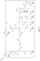
- Figs. 2-4 are schematic illustrations of examples of bridge circuits 110, or components of bridge circuits 110, that may be included in and/or utilized with power tools 10, according to the present disclosure, such as power tools 10 of Fig. 1 .
- any of the structures, functions, and/or features that are disclosed herein with reference to any bridge circuit 110 of any of Figs. 2-4 may be included in, may be utilized with, and/or may replace any other bridge circuit 110 of any other of Figs. 2-4 without departing from the scope of the present disclosure.
- bridge circuit 110 of Fig. 3 and/or bridge circuit 110 of Fig. 4 may replace, or may be substituted for, bridge circuit 110 of Fig. 2 without departing from the scope of the present disclosure.
- bridge circuit 110 includes a reference branch 120 and a detection branch 160.
- Reference branch 120 is configured to generate a reference branch signal 122 at a reference branch voltage.
- detection branch 160 is configured to generate a detection branch signal 162 at a detection branch voltage.
- Differential voltage signal 102 is a difference between the reference branch voltage and the detection branch voltage
- sensor assembly 100 and/or bridge circuit 110 thereof may include at least one bridge circuit driver 112, which may be configured to provide a bridge circuit excitation voltage 114 to bridge circuit 110.
- a single bridge circuit driver 112 may be utilized to provide a corresponding bridge circuit excitation voltage 114 to both reference branch 120 and detection branch 160.
- a variable resistor 116 may be utilized to provide phase compensation between reference branch 120 and detection branch 160.
- separate bridge circuit drivers 112 may be utilized to provide corresponding bridge circuit excitation voltages 114 to reference branch 120 and to detection branch 160.
- a voltage, a current, and/or a phase of the separate bridge circuit drivers 112 may be independently controlled and/or regulated, such as to permit and/or facilitate tuning of the bridge circuit, as discussed in more detail herein.
- bridge circuit drivers 112 include an oscillator, a voltage oscillator, and/or an alternating current voltage source.
- reference branch 120 may include a first reference branch resistor 124 and a second reference branch resistor 126.
- First reference branch resistor 124 may electrically interconnect a corresponding bridge circuit driver 112 with a reference branch output terminal 128 of reference branch 120
- second reference branch resistor 126 may electrically interconnect reference branch output terminal 128 with a signal ground 106 of the sensor assembly.
- power tools 10, according to the present disclosure may not include, or may not be in direct electrical communication with, an earth ground.
- signal ground 106 may not be, or may not be equivalent to, the earth ground, may be a floating ground, and/or may be a negative terminal of bridge circuit drivers 112, of a power supply structure for the power tool, and/or of a battery of the power tool, such as battery 54 of Fig. 1 .
- reference branch 120 also may include a tuning structure 200.
- Tuning structure 200 when present, may be configured to be utilized to tune reference branch 120. This may include tuning the reference branch such that a magnitude of the reference branch voltage is within, or set to, a threshold voltage difference of a magnitude of the detection branch voltage and/or such that a phase of the reference branch voltage is within, or set to, a threshold phase difference of a phase of the detection branch voltage.
- Examples of tuning structure 200 include a potentiometer and/or a variable resistor.
- detection branch 160 may include a first detection branch capacitor 164 and a second detection branch capacitor 166.
- First detection branch capacitor 164 may electrically interconnect a corresponding bridge circuit driver 112 with a detection branch output terminal 168 of detection branch 160
- second detection branch capacitor 166 may electrically interconnect detection branch output terminal 168 with signal ground 106.
- detection branch 160 may include a capacitive coupling structure 220.
- Capacitive coupling structure 220 may be electrically interconnected with detection branch output terminal 168 and may be configured to capacitively couple with and/or to the individual, such that the detection branch voltage is based, at least in part, on the distance between the individual and the cutting tool.
- Examples of capacitive coupling structure 220 include a galvanic and/or a capacitive coupling with and/or to cutting tool 60.
- detection branch 160 additionally may include one or more additional structures, or detection branch output terminal 168 may be electrically connected to one or more additional structures, which may be utilized to decrease noise and/or to improve capacitive coupling to the user.
- a detection branch resistor 170 may electrically interconnect detection branch output terminal 168 and signal ground 106. Detection branch resistor 170, when present, may be configured to prevent, or to discharge, electrostatic charging of detection branch 160 and/or of detection branch output terminal 168 thereof.
- test switch 172 may be utilized to selectively and electrically interconnect detection branch output terminal 168 and signal ground 106 to opposed terminals of a test capacitor 174.
- test capacitor 174 may have a capacitance that resembles, mimics, and/or approximates the capacitive coupling between the individual and the cutting tool when the individual is less than the threshold distance from the cutting tool.
- power tools 10 and/or a user of power tools 10, such as the individual may selectively close switch 172 to test the operation of sensor assembly 100 and/or to determine whether or not sensor assembly 100 is sensitive to the individual being less than the threshold distance from the cutting tool.
- a calibration switch 175 may be utilized to selectively and electrically interconnect a first varactor diode 176, a second varactor diode 177, an inductor 178 (which additionally may be referred to as a calibration inductor 178), and a variable DC source 179 between detection branch output terminal 168 and signal ground 106.
- An input to first varactor diode 176 may be configured to receive electric current flow from detection branch output terminal 168, and an output from the first varactor diode may be configured to provide the electric current flow to a node that is electrically connected with an output from second varactor diode 177.
- An input to second varactor diode 177 may be electrically connected to signal ground 106.
- Variable DC source 179 may be configured to provide an electric voltage to the node via inductor 178. When calibration switch 175 is closed, variable DC source 179 may be utilized to selectively vary a capacitive load applied to detection branch output terminal 168, such as to permit and/or facilitate calibration of bridge circuit 110 and/or to test a response of bridge circuit 110 to certain and/or specified capacitive loads.
- Figs. 2-4 illustrate bridge circuits 110 that is included in sensor assemblies 100 and that is utilized to generate differential voltage signals 102, according to the present disclosure.
- bridge circuits 110 generate reference branch signal 122 at reference branch output terminal 128 and also generate detection branch signal 162 at detection branch output terminal 168.
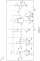
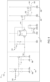
- reference branch signal 122 and/or detection branch signal 162 may be provided to one or more additional circuits prior to generation of sensor assembly output 104, and Figs. 2 and 5-6 illustrate examples of additional circuits that may receive reference branch signal 122 and/or detection branch signal 162 from the bridge circuit and produce sensor assembly output 104 therefrom.
- sensor assembly 100 may include a reference branch buffer 140, which may be electrically connected to reference branch output terminal 128.
- Fig. 2 illustrates reference branch buffer 140 electrically connected to reference branch output terminal 128 of reference branch 120
- Fig. 5 illustrates another example of reference branch buffer 140 that may be electrically connected to the reference branch output terminal and/or that may be substituted for, or may replace, reference branch buffer 140 that is illustrated in Fig. 2 .
- Reference branch buffer 140 when present, may be configured to buffer reference branch signal 122 to produce and/or generate a buffered reference branch signal 142. In such a configuration, sensor assembly output 104 may be based, at least in part, on buffered reference branch signal 142. Reference branch buffer 140 may be configured to, or may be utilized to, convert a relatively higher output impedance of the bridge circuit 110, which provides reference branch signal 122, to a relatively lower output impedance of the reference branch buffer 140 to produce and/or generate the buffered reference branch signal.
- the relatively lower output impedance of the reference branch buffer 140 may permit the buffered reference branch signal 142 to function as a loadable voltage source for subsequent circuits that receive the buffered reference branch signal and/or may decrease a magnitude of an electric current of the buffered reference branch signal when compared to reference branch signal 122.
- An example of reference branch buffer 140 includes a reference branch emitter-follower circuit 144, as illustrated in Figs. 2 and 5 .
- sensor assembly 100 may include a detection branch buffer 180, which may be electrically connected to detection branch output terminal 168.
- Fig. 2 illustrates detection branch buffer 180 electrically connected to detection branch output terminal 168 of detection branch 160
- Figs. 5-6 illustrate examples of other detection branch buffers 180 that may be electrically connected to the detection branch output terminal and/or that may be substituted for, or may replace, detection branch buffer 180 that is illustrated in Fig. 2 .
- Detection branch buffer 180 when present, may be configured to buffer detection branch signal 162 to produce and/or generate a buffered detection branch signal 182.
- sensor assembly output 104 may be based, at least in part, on buffered detection branch signal 182.
- Detection branch buffer 180 may be configured to, or may be utilized to, convert a relatively higher output impedance of the bridge circuit 110, which provides detection branch signal 162 to a relatively lower output impedance of the detection branch buffer 180 to produce and/or generate the buffered detection branch signal.
- the relatively lower output impedance of the detection branch buffer 180 may permit the buffered detection branch signal 162 to function as a loadable voltage source for subsequent circuits that receive the buffered detection branch signal and/or may decrease a magnitude of an electric current of the buffered detection branch signal when compared to detection branch signal 162.
- An example of detection branch buffer 180 includes a detection branch emitter-follower circuit 184, as illustrated in Figs. 2 and 5 .
- Another example of detection branch buffer 180 includes, or instead may be, a detection branch high pass filter 186, a detection branch low pass filter 188, and/or detection branch high pass filter 186 in series with detection branch low pass filter 188, as illustrated in Fig. 6 .
- An example of the detection branch high pass filter includes a second order Sallen-Key high pass filter.
- An example of the detection branch low pass filter includes a second order Sallen-Key low pass filter.
- reference branch buffer 140 additionally or alternatively may include, or instead may be, a reference branch high pass filter, a reference branch low pass filter, and/or the reference branch high pass filter in series with the reference branch low pass filter.
- detection branch high pass filter 186 and/or detection branch low pass filter 188 may be substituted for, or added to, reference branch buffer 140 that is illustrated in Fig. 2 without departing from the scope of the present disclosure.
- sensor assembly 100 also may include an amplifier circuit 240.
- Amplifier circuit 240 also may be referred to herein as and/or may be a differential amplifier 240.
- Amplifier circuit 240 when present, may be configured to amplify differential voltage signal 102, such as via amplification of, or of a differential voltage of, reference branch signal 122, or buffered reference branch signal 142, and detection branch signal 162, or buffered detection branch signal 182. This may include amplification to produce and/or generate an amplified differential voltage signal 242 that is based, at least in part, on the differential voltage signal.
- sensor assembly output 104 may be based, at least in part, on the amplified differential voltage signal.
- the inclusion of amplifier circuit 240 may increase a magnitude of the differential voltage signal 102 and/or increase, or improve, a signal-to-noise ratio of the differential voltage signal, thereby improving detection accuracy.
- amplifier circuit 240 may be configured to receive, or to directly receive, reference branch signal 122 and/or detection branch signal 162. In some examples, amplifier circuit 240 may be configured to receive buffered reference branch signal 142 and/or buffered detection branch signal 182.
- Figs. 2 and 5 illustrate examples of sensor assembly 100 in which amplifier circuit 240 receives buffered reference branch signal 142 and buffered detection branch signal 182.
- Fig. 6 illustrates an example of sensor assembly 100 in which amplifier circuit 240 receives reference branch signal 122 and buffered detection branch signal 182.
- Figs. 2 and 5-6 illustrate examples of amplifier circuits 240 that are configured to produce a single amplified differential voltage signal 242.
- Some examples of sensor assemblies 100 may include and/or utilize amplifier circuits 240 that may be configured to produce and/or generate a pair of outputs that together may define the amplified differential voltage signal (e.g., a voltage difference between the pair of outputs).
- Examples of such differential amplifiers include a four-arm active bridge circuit and/or a Wheatstone bridge circuit.
- amplifier circuit 240 may be configured to produce and/or generate amplified differential voltage signal 242 in the form of an amplifier output current, which may be based upon and/or proportional to the differential voltage signal.
- sensor assembly 100 may include a converter 260.
- Converter 260 when present, may be configured to receive the amplifier output current and to generate a converter output voltage 262 therefrom. The converter output voltage may be based, at least in part, on the amplifier output current, and sensor assembly output 104 may be based, at least in part, on the converter output voltage.
- An example of converter 260 includes a transimpedance converter.
- sensor assembly 100 also may include a filter 280.
- Filter 280 when present, may be configured to receive converter output voltage 262 and to produce and/or generate a filtered converter output voltage 282, such as to decrease noise within filtered converter output voltage 282 relative to converter output voltage 262 and/or to remove undesired frequency ranges, which are in the converter output voltage, from the filtered converter output voltage.
- Filtered converter output voltage 282 may be based, at least in part, on the converter output voltage
- sensor assembly output 104 may be based, at least in part, on the filtered converter output voltage.
- An example of filter 280 includes a second order multiple feedback bandpass filter.
- Power tools 10 is configured such that sensor assemblies 100 are calibrated, such as to permit and/or facilitate operation thereof.
- a method of operating power tools 10 includes blocking, or initially blocking, supply of electric current to the motor assembly and calibrating the sensor assembly. These methods also include permitting supply of electric current to the motor responsive to successful calibration of the sensor assembly.
- the calibration includes balancing the bridge circuit, such that the differential voltage signal has, or is within a threshold differential voltage of, a predetermined voltage value. In some examples, and as discussed in more detail herein, the calibration may utilize an iterative process in which adjustments are made to the bridge circuit until the differential voltage signal has the predetermined voltage value. Such a configuration may permit and/or facilitate systematic calibration of the bridge circuit and/or may permit the differential voltage signal to be set to the predetermined voltage value without requiring knowledge of the functional behavior of the differential voltage signal.
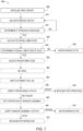
- Fig. 7 is a flowchart depicting examples of methods 400 of operating power tools, according to the present disclosure.
- Methods 400 may include initializing a first bridge circuit driver at 405, such as a first bridge circuit driver 112 of Figs. 2-4 , and balancing a bridge circuit at 410, such as bridge circuit 110 of Figs. 2-4 .
- Methods 400 then may include determining, at 415, if the balancing at 410 has been performed a threshold number of times and repeating the balancing at 410 up to the threshold number of times.
- methods 400 includes calculating a signal amplitude of a signal produced by the cutting tool at 420 and determining, at 425, if the signal amplitude is valid and/or within a predetermined amplitude range. If the signal amplitude is invalid, an error state results, as indicated at 430. If the signal amplitude is valid, methods 400 move to an optional driver amplitude adjustment at 435.
- a bias may be set.
- the bias may include and/or be a specific target, or desired value, or range, for the differential voltage signal generated by the sensor assembly and may be selected based upon any suitable criteria.
- the bias may be selected to improve, to increase, and/or to optimize sensitivity of the sensor assembly to the distance between the individual and the cutting tool and/or to the distance being less than the threshold distance.
- the bias may be equal, or at least substantially equal, to zero volts.
- the bias may be non-zero and/or may have a non-zero voltage value.
- the bias may be selected such that the sensor assembly has a high sensitivity to changes in capacitance of the capacitive coupling structure.
- Methods 400 then include verifying, at 450, operational status of the power tool. If the power tool may be released for operation, or for operative use by the user, without further testing, methods 400 may proceed to step 455. Such release at 455 may, for example, be permitted when operation of the sensor assembly recently has been verified. Stated another way, and as discussed in more detail herein, methods 400 may include optional verification of the operation of the sensor assembly, such as to ensure that the sensor assembly is calibrated, to ensure that the sensor assembly is configured to generate the differential voltage signal, and/or to ensure that the differential voltage signal is, in fact, indicative of the distance between the individual and the cutting tool being less than the threshold distance. With this in mind, and in some instances, the verifying at 450 may include permitting the power tool to be released for operation if and/or when the operation of the cutting tool recently has been verified.
- a test capacity may be applied in parallel to the cutting tool.
- Such a test capacity may, for example, be applied via test switch 172 and test capacitor 174 of Figs. 3-4 .
- Such a test capacity may be utilized to test the response of the power tool to a known and/or predefined capacitance (i.e., the test capacity), that mimics, that is similar to, that is within a similar capacitance range as, and/or that is equal to the capacitance experienced by the sensor assembly when the distance between the individual and the cutting tool is less than the threshold distance.
- a value of the differential voltage signal then may be recorded and sensitivity and/or amplification/gain adjustments may be made, such as by utilizing and/or adjusting amplifier circuit 240 of Figs. 2 and 5-6 .
- Methods 400 then may include verifying the sensor assembly output from the sensor assembly at 465. If the sensor assembly output is valid, is within a predetermined range, and/or exceeds a threshold value, verification of the sensor assembly may be complete, and methods 400 may release the power tool for operation, as indicated at 470. Alternatively, if the sensor assembly output is invalid, is outside the predetermined range, and/or is less than the threshold value, methods 400 may proceed to an error state, as indicated at 475.
- methods 500 of Fig. 8 may be utilized to perform the balancing at 410. More specifically the balancing at 410 may include initializing the second bridge circuit driver at 505 and recording a value of the differential voltage signal at 510. If the differential voltage signal is within a target value range, such as at, or near, a minimum value, and as indicated at 515, the balancing at 410 is complete, and methods 400 move to step 415 of Fig. 7 . If the target value range of the differential voltage signal has not yet been reached, methods 500 may verify, at 520, that the value of the differential voltage signal is within a predetermined control range.
- a target value range such as at, or near, a minimum value, and as indicated at 515
- methods 500 may verify, at 520, that the value of the differential voltage signal is within a predetermined control range.
- methods 500 proceed to error state 530. If the value of the differential voltage signal is outside the predetermined control range, methods 500 proceed to error state 530. If the value of the differential voltage signal is within the predetermined control range, methods 500 adjust, or iteratively adjust, the second bridge circuit driver at 525 and return to the recording at 510. The loop of steps 510, 515, 520, and 525 may be repeated until error state 530 is reached or until the target value range for the differential voltage signal is reached, thereby returning to methods 400 of Fig. 7 .
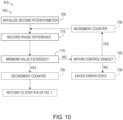
- methods 600 of Fig. 9 and/or methods 700 of Fig. 10 may be utilized to perform the balancing at 410.
- Methods 600 of Fig. 9 may be utilized to balance an amplitude of the reference branch signal and the detection branch signal.
- Methods 600 may include initializing at 605 a first potentiometer, such as tuning structure 200 of Fig. 4 , and recording a value of the differential voltage signal at 610. If a minimum value of the differential voltage signal is exceeded, and as indicated at 615, the balancing at 410 is complete, methods 600 decrement a counter at 620 before returning to step 415 of Fig. 7 .
- methods 600 proceed to step 625, where the methods determine if the value of the differential voltage signal is within the predetermined control range. If the value of the differential voltage signal is outside the predetermined control range, methods 600 proceed to an error state at 630, in which the methods may notify a user that a desired differential voltage signal was not attained, may indicate to the user that calibration may be needed, and/or may indicate a fault condition to the user. If the value of the differential voltage signal is within the predetermined control range, methods 600 increment the counter at 635 and return to step 610. The loop of steps 610, 615, 625, and 635 may be repeated until error state 630 is reached, until the counter exceeds a predetermined counter value, and/or until the amplitude is balanced, thereby returning to methods 400 of Fig. 7 .
- Methods 700 of Fig. 10 may be utilized to balance the phase of the reference branch signal and the detection branch signal, and methods 700 may include initializing at 705 a second potentiometer, such as variable resistor 116 of Fig. 4 , and recording a phase difference between the reference branch signal and the detection branch signal at 710. If a minimum value of the phase difference is exceeded, and as indicated at 715, the balancing at 410 is complete, methods 700 decrement a counter at 720 before returning to step 415 of Fig. 7 . If the minimum value of the phase difference is not exceeded, methods 700 proceed to step 725, where the methods determine if the value of the phase difference is within a predetermined control range.
- a second potentiometer such as variable resistor 116 of Fig. 4
- methods 700 proceed to an error state at 730. If the value of the phase difference is outside the predetermined control range, methods 700 increment the counter at 735 and return to step 710. The loop of steps 710, 715, 725, and 735 may be repeated until error state 730 is reached, until the counter exceeds a predetermined value, and/or until the phase is balanced, thereby returning to methods 400 of Fig. 7 .
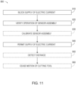
- Fig. 11 is a flowchart depicting examples of methods 800 of operating power tools, according to the present disclosure. Examples of such power tools are disclosed herein with reference to power tools 10 of Figs. 1-6 .
- Methods 800 include blocking supply of electric current at 810 and verifying operation of a sensor assembly at 820. Methods 800 also may include calibrating the sensor assembly at 830 and include permitting supply of electric current at 840. Methods 800 further may include detecting a distance at 850 and/or ceasing motion of a cutting tool at 860.
- Blocking supply of electric current at 810 may include blocking supply of electric current to a motor of the power tool. This may include blocking the supply of electric current in any suitable manner and/or utilizing any suitable structure, examples of which include a switch, a solid state switch, a transistor, a relay, and/or a controller, which may be adapted, configured, designed, constructed, and/or programmed to selectively permit and/or to selectively restrict supply of electric current to the motor of the power tool even if the user actuates a switch and/or otherwise instructs the power tool to provide the electric current to the motor.
- the power tool includes a sensor assembly, which is configured to detect when a distance between an individual and a cutting tool of the power tool is less than a threshold distance.
- verifying operation of the sensor assembly at 820 may include verifying that the sensor assembly is, is indeed, or currently is adapted, configured, programmed, and/or able to detect when and/or that the distance between the individual and the cutting tool is less than the threshold distance.
- Calibrating the sensor assembly at 830 may include calibrating the sensor assembly in any suitable manner, such as to enable the sensor assembly to detect when and/or that the distance between the individual and the cutting tool is less than the threshold distance.
- the calibrating at 830 may be, or may be performed, responsive to the verifying at 820 indicating that the sensor assembly is not, is not currently, or is not presently adapted, configured, programmed, and/or able to detect when and/or that the distance between the individual and the cutting tool is less than the threshold distance.
- the sensor assembly includes a bridge circuit, such as bridge circuit 110 that is discussed herein.
- the calibration at 830 includes balancing the bridge circuit.
- the balancing includes balancing a reference branch voltage of a reference branch of the bridge circuit and a detection branch voltage of a detection branch of the bridge circuit.
- the balancing may include balancing a reference branch phase of the reference branch and a detection branch phase of the detection branch.
- the calibrating may include setting a differential voltage signal, of the sensor assembly, to a target range.
- the target range may include 0 volts.
- the target range may exclude 0 volts, such as to increase a sensitivity of the sensor assembly to the distance between the individual and the cutting tool, as discussed in more detail herein.
- Permitting supply of electric current at 840 includes permitting supply of electric current, to the motor of the power tool, responsive to successful verification of operation of the sensor assembly. This may include permitting supply of electric current while the power tool is free of a direct connection to earth ground. Stated another way, and as discussed in more detail herein, methods 800 may be performed utilizing a cordless, or battery-powered power tool that does not include and/or utilize a connection, a direct connection, and/or a wired connection to earth ground.
- Detecting a distance at 850 may include detecting that the distance between the individual and the cutting tool is less than the threshold distance.
- the detecting at 850 may include capacitively detecting, such as via a capacitive coupling structure of the power tool. Examples of the capacitive coupling structure are disclosed herein with reference to capacitive coupling structure 220.
- the detecting at 850 may be performed subsequent to the permitting at 840 and/or may be responsive to the distance between the individual and the cutting tool being less than the threshold distance.
- the detecting at 850 may include generating the differential voltage signal, which may be indicative of the distance between the individual and the cutting tool, and/or which may be indicative that the distance between the individual and the cutting tool is less than the threshold distance.
- Ceasing motion of a cutting tool at 860 may include ceasing any suitable rotations, reciprocal, vibrational, and/or linear motion of the cutting tool, such as to protect the individual from injury, which may be caused by contact between the individual and a moving cutting tool.
- the ceasing at 860 may be responsive to the detecting at 850.
- the ceasing at 860 may be performed with, via, and/or utilizing a mechanical reaction mechanism of the power tool. Examples of the mechanical reaction mechanism are disclosed herein with reference to mechanical reaction mechanism 70.
- the term "and/or" placed between a first entity and a second entity means one of (1) the first entity, (2) the second entity, and (3) the first entity and the second entity.
- Multiple entities listed with “and/or” should be construed in the same manner, i.e., "one or more" of the entities so conjoined.
- Other entities may optionally be present other than the entities specifically identified by the "and/or” clause, whether related or unrelated to those entities specifically identified.
- a reference to "A and/or B,” when used in conjunction with open-ended language such as “comprising” may refer, in one embodiment, to A only (optionally including entities other than B); in another embodiment, to B only (optionally including entities other than A); in yet another embodiment, to both A and B (optionally including other entities).
- These entities may refer to elements, actions, structures, steps, operations, values, and the like.
- the phrase "at least one,” in reference to a list of one or more entities should be understood to mean at least one entity selected from any one or more of the entities in the list of entities, but not necessarily including at least one of each and every entity specifically listed within the list of entities and not excluding any combinations of entities in the list of entities.
- This definition also allows that entities may optionally be present other than the entities specifically identified within the list of entities to which the phrase "at least one" refers, whether related or unrelated to those entities specifically identified.
- At least one of A and B may refer, in one embodiment, to at least one, optionally including more than one, A, with no B present (and optionally including entities other than B); in another embodiment, to at least one, optionally including more than one, B, with no A present (and optionally including entities other than A); in yet another embodiment, to at least one, optionally including more than one, A, and at least one, optionally including more than one, B (and optionally including other entities).
- each of the expressions “at least one of A, B, and C,” “at least one of A, B, or C,” “one or more of A, B, and C,” “one or more of A, B, or C,” and “A, B, and/or C” may mean A alone, B alone, C alone, A and B together, A and C together, B and C together, A, B, and C together, and optionally any of the above in combination with at least one other entity.
- adapted and “configured” mean that the element, component, or other subject matter is designed and/or intended to perform a given function.
- the use of the terms “adapted” and “configured” should not be construed to mean that a given element, component, or other subject matter is simply “capable of” performing a given function but that the element, component, and/or other subject matter is specifically selected, created, implemented, utilized, programmed, and/or designed for the purpose of performing the function.
- elements, components, and/or other recited subject matter that is recited as being adapted to perform a particular function may additionally or alternatively be described as being configured to perform that function, and vice versa.
- the phrase, "for example,” the phrase, “as an example,” and/or simply the term “example,” when used with reference to one or more components, features, details, structures, embodiments, and/or methods according to the present disclosure, are intended to convey that the described component, feature, detail, structure, embodiment, and/or method is an illustrative, non-exclusive example of components, features, details, structures, embodiments, and/or methods according to the present disclosure.
- an object that is at least substantially formed from a material includes objects for which at least 75% of the objects are formed from the material and also includes objects that are completely formed from the material.
- a first length that is at least substantially as long as a second length includes first lengths that are within 75% of the second length and also includes first lengths that are as long as the second length.
- the power tools and methods disclosed herein are applicable to the power tool industry.
Landscapes
- Engineering & Computer Science (AREA)
- Mechanical Engineering (AREA)
- General Engineering & Computer Science (AREA)
- Portable Power Tools In General (AREA)
- Transmission And Conversion Of Sensor Element Output (AREA)
- Drilling And Boring (AREA)
- Sawing (AREA)
- Grinding-Machine Dressing And Accessory Apparatuses (AREA)
- Finish Polishing, Edge Sharpening, And Grinding By Specific Grinding Devices (AREA)
Claims (15)
- Angetriebenes Werkzeug (10) umfassend:einen Motor (20) mit einer Motorwelle (22), die dazu ausgebildet ist, um eine Wellenrotationsachse (24) zu rotieren, wobei der Motor (20) dazu ausgebildet ist, ein Schneidwerkzeug (60) zum Schneiden eines Werkstücks anzutreiben;eine Sensorbaugruppe (100), die dazu ausgebildet ist, ein Differenzspannungssignal (102) zu erzeugen, das einen Abstand zwischen einer Person und dem Schneidwerkzeug (60) kennzeichnet, der kleiner als ein Schwellenabstand ist, und eine Sensorbaugruppen-Ausgabe (104) zu erzeugen, die auf dem Differenzspannungssignal (102) basiert;eine Analyseschaltung (300), die dazu ausgebildet ist, die Sensorbaugruppen-Ausgabe (104) zu empfangen und in Reaktion auf eine außerhalb eines nominellen Sensorbaugruppen-Ausgabebereichs liegende Sensorbaugruppen-Ausgabe (104) ein Triggersignal (302) zu erzeugen; undeinen mechanischen Reaktionsmechanismus (70), der dazu ausgebildet ist, die Person in Reaktion auf den Empfang des Triggersignals (302) von dem Schneidwerkzeug (60) zu isolieren,dadurch gekennzeichnet,
dass die Sensorbaugruppe (100) eine Brückenschaltung (110) umfasst, die dazu ausgebildet ist, das Differenzspannungssignal (102) zu erzeugen, wobei die Brückenschaltung (110) einen Referenzzweig (120) umfasst, der dazu ausgebildet ist, ein Referenzzweigsignal (122) mit einer Referenzzweigspannung zu erzeugen, und einen Detektionszweig (160), der dazu ausgebildet ist, ein Detektionszweigsignal (162) mit einer Detektionszweigspannung zu erzeugen, und wobei ferner das Differenzspannungssignal (102) eine Differenz zwischen der Referenzzweigspannung und der Detektionszweigspannung umfasst. - Angetriebenes Werkzeug (10) nach Anspruch 1, wobei die Brückenschaltung (110) einen Brückenschaltungs-Oszillator umfasst, der dazu ausgebildet ist, eine Brückenschaltungs-Erregungsspannung an den Referenzzweig (120) und auch an den Detektionszweig (160) zu liefern, und/oder wobei die Brückenschaltung (110) einen Referenzzweig-Oszillator umfasst, der dazu ausgebildet ist, eine Referenzzweig-Erregungsspannung an den Referenzzweig (120) zu liefern, und einen Detektionszweig-Oszillator, der dazu ausgebildet ist, eine Detektionszweig-Erregungsspannung an den Detektionszweig (160) zu liefern.
- Angetriebenes Werkzeug (10) nach einem der Ansprüche 1 bis 2, wobei der Referenzzweig (120) eine Abstimmstruktur (200) aufweist, die dazu ausgebildet ist, den Referenzzweig (120) so abzustimmen, dass mindestens eines von Folgendem erreicht wird:(i) eine Größe der Spannung des Referenzzweigs liegt innerhalb einer Schwellenspannungsdifferenz zu einem Betrag der Spannung des Detektionszweigs; und(ii) eine Phase der Referenzzweigspannung liegt innerhalb einer Schwellenphasendifferenz einer Phase der Detektionszweigspannung, und/oder wobei der Detektionszweig (160) eine kapazitive Kopplungsstruktur (220) umfasst, die dazu ausgebildet ist, kapazitiv an die Person anzukoppeln, so dass die Detektionszweigspannung zumindest teilweise auf dem Abstand zwischen der Person und dem Schneidwerkzeug (60) basiert,und/oder wobei die Sensorbaugruppe (100) ferner einen Referenzzweigpuffer (140) aufweist, der dazu ausgebildet ist, das Referenzzweigsignal (122) zu puffern, um ein gepuffertes Referenzzweigsignal (142) zu erzeugen, wobei die Sensorbaugruppen-Ausgabe (104) zumindest teilweise auf dem gepufferten Referenzzweigsignal (142) basiert,
und/oder wobei die Sensorbaugruppe (100) ferner einen Detektionszweigpuffer (180) aufweist, der dazu ausgebildet ist, das Detektionszweigsignal (162) zu puffern, um ein gepuffertes Detektionszweigsignal (162) zu erzeugen, wobei die Sensorbaugruppen-Ausgabe (104) zumindest teilweise auf dem gepufferten Detektionszweigsignal (162) basiert. - Angetriebenes Werkzeug (10) nach einem der Ansprüche 1 bis 3, wobei die Sensorbaugruppe (100) ferner eine Verstärkerschaltung (240) umfasst, die dazu ausgebildet ist, das Differenzspannungssignal (102) zu verstärken, um ein verstärktes Differenzspannungssignal (242) zu erzeugen, wobei die Sensorbaugruppen-Ausgabe (104) zumindest teilweise auf dem verstärkten Differenzspannungssignal (242) basiert.
- Angetriebenes Werkzeug (10) nach Anspruch 4, wobei die Verstärkerschaltung (240) dazu ausgebildet ist, einen Verstärkerausgangsstrom zu erzeugen, und wobei ferner die Sensorbaugruppe (100) einen Wandler (260) aufweist, der dazu ausgebildet ist, den Verstärkerausgangsstrom zu empfangen und eine Wandlerausgangsspannung zu erzeugen, wobei die Wandlerausgangsspannung zumindest teilweise auf dem Verstärkerausgangsstrom basiert, und wobei ferner die Sensorbaugruppen-Ausgabe (104) zumindest teilweise auf der Wandlerausgangsspannung basiert, wobei vorzugsweise die Verstärkerschaltung (240) ferner einen Filter aufweist, der dazu ausgebildet ist, die Wandlerausgangsspannung zu empfangen und eine gefilterte Wandlerausgangsspannung zu erzeugen,
wobei vorzugsweise die gefilterte Wandlerausgangsspannung zumindest teilweise auf der Wandlerausgangsspannung basiert, und wobei weiter vorzugsweise die Sensorbaugruppen-Ausgabe (104) zumindest teilweise auf der gefilterten Wandlerausgangsspannung basiert. - Angetriebenes Werkzeug (10) nach einem der Ansprüche 1 bis 5, wobei das angetriebene Werkzeug (10) ferner eine Schneidwerkzeug-Isolationsstruktur (62) aufweist, die dazu ausgebildet ist, das Schneidwerkzeug (60) von mindestens einer anderen Komponente des angetriebenen Werkzeugs (10) elektrisch zu isolieren.
- Angetriebenes Werkzeug (10) nach einem der Ansprüche 1 bis 6, wobei der mechanische Reaktionsmechanismus (70) dazu ausgebildet ist, mindestens einen der folgenden Schritte auszuführen:(i) selektives Beenden des Antreibens des Schneidwerkzeugs (60) als Reaktion auf den Empfang des Triggersignals (302);(ii) selektives Beenden des Antreibens des Schneidwerkzeugs (60) durch den Motor (20) als Reaktion auf den Empfang des Triggersignals (302);(iii) selektives Zurückziehen des Schneidwerkzeugs (60) in das angetriebene Werkzeug (10) als Reaktion auf den Empfang des Triggersignals (302);(iv) selektives Abtrennen des Schneidwerkzeugs (60) als Reaktion auf den Empfang des Triggersignals (302); und(v) selektives Positionieren einer Schutzstruktur zwischen der Person und dem Schneidwerkzeug (60) als Reaktion auf den Empfang des Triggersignals (302).
- Das angetriebene Werkzeug (10) nach einem der Ansprüche 1 bis 7, wobei das angetriebene Werkzeug (10) ein batteriebetriebenes Werkzeug ist, und/oder wobei das angetriebene Werkzeug (10) keine direkte Verbindung zur Erde hat,
und/oder wobei das angetriebene Werkzeug (10) mindestens eines der Folgenden umfasst:(i) eine Säge;(ii) eine Kreissäge;(iii) eine handgeführte Kreissäge;(iv) eine Gehrungssäge;(v) eine Radialarmsäge(vi) eine Tischsäge;(vii) eine Kappsäge(viii) eine Tauchsäge(ix) eine Schienensäge;(x) eine Bandsäge;(xi) eine Stichsäge;(xii) eine Aufwärtsschnittsäge;(xiii) eine Plattensäge;(xiv) ein rotierendes Schneidwerkzeug;(xv) eine Oberfräse;(xvi) eine Bohrmaschine; und(xvii) eine Hobelmaschine,
und/oder wobei das angetriebene Werkzeug (10) mindestens eines der Folgenden umfasst:(xviii) ein handgehaltenes angetriebenes Werkzeug; und(xix) ein tragbares angetriebenes Werkzeug, und/oder wobei das Schneidwerkzeug (60) mindestens eines der Folgenden umfasst:(i) eine Klinge;(ii) ein Sägeblatt;(iii) ein Kreissägeblatt;(iv) ein Bit;(v) eine Oberfräserspitze;(vi) eine Bohrerspitze; und(vii) ein rotierendes Schneidstück. - Verfahren zum Betreiben eines angetriebenen Werkzeugs (10), wobei das Verfahren umfasst:Sperren der Zufuhr von elektrischem Strom zu einem Motor (20) des angetriebenen Werkzeugs (10);Verifizieren des Betriebs einer Sensorbaugruppe (100) des angetriebenen Werkzeugs (10), wobei die Sensorbaugruppe (100) dazu ausgebildet ist, ein Differenzspannungssignal (102) zu erzeugen, das einen Abstand zwischen einer Person und einem Schneidwerkzeug (60) des angetriebenen Werkzeugs (10) kennzeichnet, der geringer ist als ein Schwellenabstand; undZulassen der Zufuhr von elektrischem Strom zum Motor (20) in Reaktion auf eine erfolgreiche Verifizierung des Betriebs der Sensorbaugruppe (100), wobei das Verfahren ferner das Kalibrieren der Sensorbaugruppe (100) umfasst, wobei die Sensorbaugruppe (100) eine Brückenschaltung (110) umfasst, und wobei ferner das Kalibrieren das Abgleichen der Brückenschaltung (110) umfasst, und wobei das Abgleichen der Brückenschaltung (110) das Abgleichen einer Referenzzweigspannung eines Referenzzweigs der Brückenschaltung (110) und einer Detektionszweigspannung eines Detektionszweigs (160) der Brückenschaltung (110) umfasst.
- Verfahren nach Anspruch 9, wobei das Abgleichen der Brückenschaltung (110) das Abgleichen einer Referenzzweigphase des Referenzzweigs (120) der Brückenschaltung (110) und einer Detektionszweigphase des Detektionszweigs (160) der Brückenschaltung (110) umfasst.
- Verfahren nach einem der Ansprüche 9-10, wobei das Kalibrieren das Einstellen des Differenzspannungssignals (102) auf einen Zielbereich umfasst, wobei der Zielbereich vorzugsweise 0 Volt einschließt, oder wobei der Zielbereich vorzugsweise 0 Volt ausschließt.
- Verfahren nach einem der Ansprüche 9 bis 11, wobei das Kalibrieren darauf reagiert, dass die Verifizierung anzeigt, dass die Sensorbaugruppe (100) nicht dazu konfiguriert ist, zu erkennen, wenn der Abstand zwischen der Person und dem Schneidwerkzeug (60) geringer als der Schwellenabstand ist.
- Verfahren nach einem der Ansprüche 9 bis 12, wobei das Verfahren im Anschluss an das Zulassen ferner das Erfassen des Umstands umfasst, dass der Abstand zwischen der Person und dem Schneidwerkzeug (60) geringer als der Schwellenabstand ist, wobei das Verifizieren vorzugsweise das Verifizieren des Umstands umfasst, dass die Sensorbaugruppe (100) dazu konfiguriert ist, zu erfassen, dass der Abstand zwischen der Person und dem Schneidwerkzeug (60) geringer als der Schwellenabstand ist.
- Verfahren nach einem der Ansprüche 9-13, wobei die Erfassung eine kapazitive Erfassung unter Verwendung einer kapazitiven Kopplungsstruktur (220) des angetriebenen Werkzeugs (10) umfasst,und/oder wobei das Erfassen ferner das Erzeugen des Differenzspannungssignals (102) umfasst, das kennzeichnet, dass der Abstand zwischen der Person und dem Schneidwerkzeug (60) geringer als der Schwellenabstand ist,und/oder wobei das Verfahren in Reaktion auf das Erfassen ferner das Beenden der Bewegung des Schneidwerkzeugs (60) umfasst.
- Verfahren nach einem der Ansprüche 9 bis 14, wobei das Zulassen der Zufuhr von elektrischem Strom das Zulassen der Zufuhr von elektrischem Strom umfasst, während das angetriebene Werkzeug (10) keine direkte Verbindung zur Erde hat.
Priority Applications (1)
| Application Number | Priority Date | Filing Date | Title |
|---|---|---|---|
| EP24180329.5A EP4461471A3 (de) | 2020-07-01 | 2021-06-24 | Elektrowerkzeuge und verfahren zum betrieb von elektrowerkzeugen |
Applications Claiming Priority (2)
| Application Number | Priority Date | Filing Date | Title |
|---|---|---|---|
| US202063046975P | 2020-07-01 | 2020-07-01 | |
| PCT/EP2021/067382 WO2022002756A1 (en) | 2020-07-01 | 2021-06-24 | Power tools and methods of operating power tools |
Related Child Applications (2)
| Application Number | Title | Priority Date | Filing Date |
|---|---|---|---|
| EP24180329.5A Division EP4461471A3 (de) | 2020-07-01 | 2021-06-24 | Elektrowerkzeuge und verfahren zum betrieb von elektrowerkzeugen |
| EP24180329.5A Division-Into EP4461471A3 (de) | 2020-07-01 | 2021-06-24 | Elektrowerkzeuge und verfahren zum betrieb von elektrowerkzeugen |
Publications (2)
| Publication Number | Publication Date |
|---|---|
| EP4175789A1 EP4175789A1 (de) | 2023-05-10 |
| EP4175789B1 true EP4175789B1 (de) | 2024-08-07 |
Family
ID=76708226
Family Applications (2)
| Application Number | Title | Priority Date | Filing Date |
|---|---|---|---|
| EP24180329.5A Pending EP4461471A3 (de) | 2020-07-01 | 2021-06-24 | Elektrowerkzeuge und verfahren zum betrieb von elektrowerkzeugen |
| EP21736295.3A Active EP4175789B1 (de) | 2020-07-01 | 2021-06-24 | Elektrowerkzeuge und verfahren zum betrieb von elektrowerkzeugen |
Family Applications Before (1)
| Application Number | Title | Priority Date | Filing Date |
|---|---|---|---|
| EP24180329.5A Pending EP4461471A3 (de) | 2020-07-01 | 2021-06-24 | Elektrowerkzeuge und verfahren zum betrieb von elektrowerkzeugen |
Country Status (6)
| Country | Link |
|---|---|
| US (1) | US20230286097A1 (de) |
| EP (2) | EP4461471A3 (de) |
| JP (1) | JP7578719B2 (de) |
| CN (1) | CN115803152B (de) |
| TW (1) | TWI907455B (de) |
| WO (1) | WO2022002756A1 (de) |
Family Cites Families (17)
| Publication number | Priority date | Publication date | Assignee | Title |
|---|---|---|---|---|
| US3222504A (en) * | 1961-06-23 | 1965-12-07 | Western Electric Co | Monitoring system for controlling a component fabricating machine |
| US3462692A (en) * | 1967-03-27 | 1969-08-19 | Bliss Co | Pedestrian detection system |
| US3785230A (en) * | 1972-11-08 | 1974-01-15 | Lokey Tool Inc | Automatic safety brake for rotary blade equipment |
| US3886413A (en) * | 1973-01-29 | 1975-05-27 | Xenex Corp | Presence sensing and self-checking control system |
| US4335339A (en) * | 1979-11-20 | 1982-06-15 | Brickner Joseph L | Electronic safety device |
| JP3972064B2 (ja) * | 1999-04-02 | 2007-09-05 | 独立行政法人労働安全衛生総合研究所 | センサ装置及び安全装置 |
| US9724840B2 (en) * | 1999-10-01 | 2017-08-08 | Sd3, Llc | Safety systems for power equipment |
| US7971613B2 (en) | 2007-12-31 | 2011-07-05 | Sd3, Llc | Detection systems for power equipment |
| US7536238B2 (en) | 2003-12-31 | 2009-05-19 | Sd3, Llc | Detection systems for power equipment |
| US6286609B1 (en) * | 1999-12-10 | 2001-09-11 | Black & Decker Inc. | AC/DC chopper for power tool |
| EP1537665B1 (de) * | 2002-08-16 | 2008-10-15 | Intelligent Mechatronic Systems, Inc. | Kapazitive berührungsaktivierbare scahltvorrichtung |
| EP1836434A2 (de) * | 2004-12-09 | 2007-09-26 | Ident Technology AG | Ger[tesicherungssystem zum abgesicherten betrieb von gef[hrdungsrelevanten motorger[ten, insbesondere gartenger[ten und werkzeugen |
| US8122798B1 (en) * | 2008-11-19 | 2012-02-28 | Power Tool Institute | Power cutting tool with proximity sensing system |
| CN102566502A (zh) * | 2010-12-28 | 2012-07-11 | 鸿富锦精密工业(深圳)有限公司 | 人体接近感应装置 |
| TWI682821B (zh) * | 2015-03-12 | 2020-01-21 | 德商羅伯特博斯奇股份有限公司 | 轉向臂重置方法 |
| WO2017210091A1 (en) | 2016-05-31 | 2017-12-07 | Sd3, Llc | Detection systems for power tools with active injury mitigation technology |
| EP3676055B1 (de) * | 2017-08-30 | 2022-07-20 | Milwaukee Electric Tool Corporation | Werkzeugmaschine mit objektdetektion |
-
2021
- 2021-06-24 JP JP2022565872A patent/JP7578719B2/ja active Active
- 2021-06-24 CN CN202180046990.0A patent/CN115803152B/zh active Active
- 2021-06-24 EP EP24180329.5A patent/EP4461471A3/de active Pending
- 2021-06-24 EP EP21736295.3A patent/EP4175789B1/de active Active
- 2021-06-24 US US18/001,534 patent/US20230286097A1/en active Pending
- 2021-06-24 WO PCT/EP2021/067382 patent/WO2022002756A1/en not_active Ceased
- 2021-07-01 TW TW110124212A patent/TWI907455B/zh active
Also Published As
| Publication number | Publication date |
|---|---|
| WO2022002756A1 (en) | 2022-01-06 |
| EP4461471A2 (de) | 2024-11-13 |
| TW202209027A (zh) | 2022-03-01 |
| TWI907455B (zh) | 2025-12-11 |
| CN115803152B (zh) | 2025-11-28 |
| JP2023523348A (ja) | 2023-06-02 |
| EP4175789A1 (de) | 2023-05-10 |
| JP7578719B2 (ja) | 2024-11-06 |
| US20230286097A1 (en) | 2023-09-14 |
| CN115803152A (zh) | 2023-03-14 |
| EP4461471A3 (de) | 2025-02-19 |
Similar Documents
| Publication | Publication Date | Title |
|---|---|---|
| US11192232B2 (en) | Power tool with anti-kickback control system | |
| US7681659B2 (en) | Power tool anti-kickback system with rotational rate sensor | |
| US11015759B2 (en) | Power tool and kickback detection method therefor | |
| US7077039B2 (en) | Detection system for power equipment | |
| US20090195204A1 (en) | Power Tool Having Motor Speed Monitor | |
| US7403131B2 (en) | Power tool movement monitor and operating system | |
| JPH09285944A (ja) | 空気軸受式工作機械の主軸異常検出装置 | |
| EP4175789B1 (de) | Elektrowerkzeuge und verfahren zum betrieb von elektrowerkzeugen | |
| US9586336B2 (en) | Kickback detection system | |
| US12558814B2 (en) | Hand-held electrically powered cut-off tool with a kickback mitigation function | |
| US20240300063A1 (en) | Detection systems for aim-enabled power tools | |
| CN119278114A (zh) | 用于检测电动工具的反冲的方法 | |
| US11964334B2 (en) | Technique for measuring electric current flowing in electric powered work machine | |
| WO2018062293A1 (ja) | 作業機 | |
| KR101902293B1 (ko) | 양방향 dc모터를 위한 누설전류 감지 시스템 | |
| US20060022629A1 (en) | Numerical control device |
Legal Events
| Date | Code | Title | Description |
|---|---|---|---|
| STAA | Information on the status of an ep patent application or granted ep patent |
Free format text: STATUS: UNKNOWN |
|
| STAA | Information on the status of an ep patent application or granted ep patent |
Free format text: STATUS: THE INTERNATIONAL PUBLICATION HAS BEEN MADE |
|
| PUAI | Public reference made under article 153(3) epc to a published international application that has entered the european phase |
Free format text: ORIGINAL CODE: 0009012 |
|
| STAA | Information on the status of an ep patent application or granted ep patent |
Free format text: STATUS: REQUEST FOR EXAMINATION WAS MADE |
|
| 17P | Request for examination filed |
Effective date: 20230201 |
|
| AK | Designated contracting states |
Kind code of ref document: A1 Designated state(s): AL AT BE BG CH CY CZ DE DK EE ES FI FR GB GR HR HU IE IS IT LI LT LU LV MC MK MT NL NO PL PT RO RS SE SI SK SM TR |
|
| DAV | Request for validation of the european patent (deleted) | ||
| DAX | Request for extension of the european patent (deleted) | ||
| GRAP | Despatch of communication of intention to grant a patent |
Free format text: ORIGINAL CODE: EPIDOSNIGR1 |
|
| STAA | Information on the status of an ep patent application or granted ep patent |
Free format text: STATUS: GRANT OF PATENT IS INTENDED |
|
| INTG | Intention to grant announced |
Effective date: 20240125 |
|
| P01 | Opt-out of the competence of the unified patent court (upc) registered |
Effective date: 20240315 |
|
| GRAS | Grant fee paid |
Free format text: ORIGINAL CODE: EPIDOSNIGR3 |
|
| GRAA | (expected) grant |
Free format text: ORIGINAL CODE: 0009210 |
|
| STAA | Information on the status of an ep patent application or granted ep patent |
Free format text: STATUS: THE PATENT HAS BEEN GRANTED |
|
| AK | Designated contracting states |
Kind code of ref document: B1 Designated state(s): AL AT BE BG CH CY CZ DE DK EE ES FI FR GB GR HR HU IE IS IT LI LT LU LV MC MK MT NL NO PL PT RO RS SE SI SK SM TR |
|
| REG | Reference to a national code |
Ref country code: GB Ref legal event code: FG4D |
|
| REG | Reference to a national code |
Ref country code: CH Ref legal event code: EP |
|
| REG | Reference to a national code |
Ref country code: IE Ref legal event code: FG4D |
|
| REG | Reference to a national code |
Ref country code: DE Ref legal event code: R096 Ref document number: 602021016880 Country of ref document: DE |
|
| REG | Reference to a national code |
Ref country code: NL Ref legal event code: FP |
|
| REG | Reference to a national code |
Ref country code: LT Ref legal event code: MG9D |
|
| PG25 | Lapsed in a contracting state [announced via postgrant information from national office to epo] |
Ref country code: NO Free format text: LAPSE BECAUSE OF FAILURE TO SUBMIT A TRANSLATION OF THE DESCRIPTION OR TO PAY THE FEE WITHIN THE PRESCRIBED TIME-LIMIT Effective date: 20241107 |
|
| REG | Reference to a national code |
Ref country code: AT Ref legal event code: MK05 Ref document number: 1710429 Country of ref document: AT Kind code of ref document: T Effective date: 20240807 |
|
| PG25 | Lapsed in a contracting state [announced via postgrant information from national office to epo] |
Ref country code: PL Free format text: LAPSE BECAUSE OF FAILURE TO SUBMIT A TRANSLATION OF THE DESCRIPTION OR TO PAY THE FEE WITHIN THE PRESCRIBED TIME-LIMIT Effective date: 20240807 Ref country code: GR Free format text: LAPSE BECAUSE OF FAILURE TO SUBMIT A TRANSLATION OF THE DESCRIPTION OR TO PAY THE FEE WITHIN THE PRESCRIBED TIME-LIMIT Effective date: 20241108 Ref country code: FI Free format text: LAPSE BECAUSE OF FAILURE TO SUBMIT A TRANSLATION OF THE DESCRIPTION OR TO PAY THE FEE WITHIN THE PRESCRIBED TIME-LIMIT Effective date: 20240807 Ref country code: PT Free format text: LAPSE BECAUSE OF FAILURE TO SUBMIT A TRANSLATION OF THE DESCRIPTION OR TO PAY THE FEE WITHIN THE PRESCRIBED TIME-LIMIT Effective date: 20241209 |
|
| PG25 | Lapsed in a contracting state [announced via postgrant information from national office to epo] |
Ref country code: BG Free format text: LAPSE BECAUSE OF FAILURE TO SUBMIT A TRANSLATION OF THE DESCRIPTION OR TO PAY THE FEE WITHIN THE PRESCRIBED TIME-LIMIT Effective date: 20240807 |
|
| PG25 | Lapsed in a contracting state [announced via postgrant information from national office to epo] |
Ref country code: LV Free format text: LAPSE BECAUSE OF FAILURE TO SUBMIT A TRANSLATION OF THE DESCRIPTION OR TO PAY THE FEE WITHIN THE PRESCRIBED TIME-LIMIT Effective date: 20240807 |
|
| PG25 | Lapsed in a contracting state [announced via postgrant information from national office to epo] |
Ref country code: AT Free format text: LAPSE BECAUSE OF FAILURE TO SUBMIT A TRANSLATION OF THE DESCRIPTION OR TO PAY THE FEE WITHIN THE PRESCRIBED TIME-LIMIT Effective date: 20240807 Ref country code: IS Free format text: LAPSE BECAUSE OF FAILURE TO SUBMIT A TRANSLATION OF THE DESCRIPTION OR TO PAY THE FEE WITHIN THE PRESCRIBED TIME-LIMIT Effective date: 20241207 |
|
| PG25 | Lapsed in a contracting state [announced via postgrant information from national office to epo] |
Ref country code: HR Free format text: LAPSE BECAUSE OF FAILURE TO SUBMIT A TRANSLATION OF THE DESCRIPTION OR TO PAY THE FEE WITHIN THE PRESCRIBED TIME-LIMIT Effective date: 20240807 |
|
| PG25 | Lapsed in a contracting state [announced via postgrant information from national office to epo] |
Ref country code: ES Free format text: LAPSE BECAUSE OF FAILURE TO SUBMIT A TRANSLATION OF THE DESCRIPTION OR TO PAY THE FEE WITHIN THE PRESCRIBED TIME-LIMIT Effective date: 20240807 Ref country code: RS Free format text: LAPSE BECAUSE OF FAILURE TO SUBMIT A TRANSLATION OF THE DESCRIPTION OR TO PAY THE FEE WITHIN THE PRESCRIBED TIME-LIMIT Effective date: 20241107 |
|
| PG25 | Lapsed in a contracting state [announced via postgrant information from national office to epo] |
Ref country code: RS Free format text: LAPSE BECAUSE OF FAILURE TO SUBMIT A TRANSLATION OF THE DESCRIPTION OR TO PAY THE FEE WITHIN THE PRESCRIBED TIME-LIMIT Effective date: 20241107 Ref country code: PT Free format text: LAPSE BECAUSE OF FAILURE TO SUBMIT A TRANSLATION OF THE DESCRIPTION OR TO PAY THE FEE WITHIN THE PRESCRIBED TIME-LIMIT Effective date: 20241209 Ref country code: PL Free format text: LAPSE BECAUSE OF FAILURE TO SUBMIT A TRANSLATION OF THE DESCRIPTION OR TO PAY THE FEE WITHIN THE PRESCRIBED TIME-LIMIT Effective date: 20240807 Ref country code: NO Free format text: LAPSE BECAUSE OF FAILURE TO SUBMIT A TRANSLATION OF THE DESCRIPTION OR TO PAY THE FEE WITHIN THE PRESCRIBED TIME-LIMIT Effective date: 20241107 Ref country code: LV Free format text: LAPSE BECAUSE OF FAILURE TO SUBMIT A TRANSLATION OF THE DESCRIPTION OR TO PAY THE FEE WITHIN THE PRESCRIBED TIME-LIMIT Effective date: 20240807 Ref country code: IS Free format text: LAPSE BECAUSE OF FAILURE TO SUBMIT A TRANSLATION OF THE DESCRIPTION OR TO PAY THE FEE WITHIN THE PRESCRIBED TIME-LIMIT Effective date: 20241207 Ref country code: HR Free format text: LAPSE BECAUSE OF FAILURE TO SUBMIT A TRANSLATION OF THE DESCRIPTION OR TO PAY THE FEE WITHIN THE PRESCRIBED TIME-LIMIT Effective date: 20240807 Ref country code: GR Free format text: LAPSE BECAUSE OF FAILURE TO SUBMIT A TRANSLATION OF THE DESCRIPTION OR TO PAY THE FEE WITHIN THE PRESCRIBED TIME-LIMIT Effective date: 20241108 Ref country code: FI Free format text: LAPSE BECAUSE OF FAILURE TO SUBMIT A TRANSLATION OF THE DESCRIPTION OR TO PAY THE FEE WITHIN THE PRESCRIBED TIME-LIMIT Effective date: 20240807 Ref country code: ES Free format text: LAPSE BECAUSE OF FAILURE TO SUBMIT A TRANSLATION OF THE DESCRIPTION OR TO PAY THE FEE WITHIN THE PRESCRIBED TIME-LIMIT Effective date: 20240807 Ref country code: BG Free format text: LAPSE BECAUSE OF FAILURE TO SUBMIT A TRANSLATION OF THE DESCRIPTION OR TO PAY THE FEE WITHIN THE PRESCRIBED TIME-LIMIT Effective date: 20240807 Ref country code: AT Free format text: LAPSE BECAUSE OF FAILURE TO SUBMIT A TRANSLATION OF THE DESCRIPTION OR TO PAY THE FEE WITHIN THE PRESCRIBED TIME-LIMIT Effective date: 20240807 |
|
| PG25 | Lapsed in a contracting state [announced via postgrant information from national office to epo] |
Ref country code: DK Free format text: LAPSE BECAUSE OF FAILURE TO SUBMIT A TRANSLATION OF THE DESCRIPTION OR TO PAY THE FEE WITHIN THE PRESCRIBED TIME-LIMIT Effective date: 20240807 Ref country code: SM Free format text: LAPSE BECAUSE OF FAILURE TO SUBMIT A TRANSLATION OF THE DESCRIPTION OR TO PAY THE FEE WITHIN THE PRESCRIBED TIME-LIMIT Effective date: 20240807 |
|
| PG25 | Lapsed in a contracting state [announced via postgrant information from national office to epo] |
Ref country code: EE Free format text: LAPSE BECAUSE OF FAILURE TO SUBMIT A TRANSLATION OF THE DESCRIPTION OR TO PAY THE FEE WITHIN THE PRESCRIBED TIME-LIMIT Effective date: 20240807 |
|
| PG25 | Lapsed in a contracting state [announced via postgrant information from national office to epo] |
Ref country code: CZ Free format text: LAPSE BECAUSE OF FAILURE TO SUBMIT A TRANSLATION OF THE DESCRIPTION OR TO PAY THE FEE WITHIN THE PRESCRIBED TIME-LIMIT Effective date: 20240807 |
|
| PG25 | Lapsed in a contracting state [announced via postgrant information from national office to epo] |
Ref country code: SK Free format text: LAPSE BECAUSE OF FAILURE TO SUBMIT A TRANSLATION OF THE DESCRIPTION OR TO PAY THE FEE WITHIN THE PRESCRIBED TIME-LIMIT Effective date: 20240807 |
|
| REG | Reference to a national code |
Ref country code: DE Ref legal event code: R097 Ref document number: 602021016880 Country of ref document: DE |
|
| PLBE | No opposition filed within time limit |
Free format text: ORIGINAL CODE: 0009261 |
|
| STAA | Information on the status of an ep patent application or granted ep patent |
Free format text: STATUS: NO OPPOSITION FILED WITHIN TIME LIMIT |
|
| PGFP | Annual fee paid to national office [announced via postgrant information from national office to epo] |
Ref country code: DE Payment date: 20250618 Year of fee payment: 5 |
|
| PGFP | Annual fee paid to national office [announced via postgrant information from national office to epo] |
Ref country code: GB Payment date: 20250618 Year of fee payment: 5 |
|
| PGFP | Annual fee paid to national office [announced via postgrant information from national office to epo] |
Ref country code: NL Payment date: 20250618 Year of fee payment: 5 |
|
| 26N | No opposition filed |
Effective date: 20250508 |
|
| PGFP | Annual fee paid to national office [announced via postgrant information from national office to epo] |
Ref country code: FR Payment date: 20250627 Year of fee payment: 5 |
|
| PG25 | Lapsed in a contracting state [announced via postgrant information from national office to epo] |
Ref country code: SE Free format text: LAPSE BECAUSE OF FAILURE TO SUBMIT A TRANSLATION OF THE DESCRIPTION OR TO PAY THE FEE WITHIN THE PRESCRIBED TIME-LIMIT Effective date: 20240807 |
|
| REG | Reference to a national code |
Ref country code: CH Ref legal event code: H13 Free format text: ST27 STATUS EVENT CODE: U-0-0-H10-H13 (AS PROVIDED BY THE NATIONAL OFFICE) Effective date: 20260127 |
|
| PG25 | Lapsed in a contracting state [announced via postgrant information from national office to epo] |
Ref country code: IT Free format text: LAPSE BECAUSE OF FAILURE TO SUBMIT A TRANSLATION OF THE DESCRIPTION OR TO PAY THE FEE WITHIN THE PRESCRIBED TIME-LIMIT Effective date: 20240807 |
|
| PG25 | Lapsed in a contracting state [announced via postgrant information from national office to epo] |
Ref country code: MC Free format text: LAPSE BECAUSE OF FAILURE TO SUBMIT A TRANSLATION OF THE DESCRIPTION OR TO PAY THE FEE WITHIN THE PRESCRIBED TIME-LIMIT Effective date: 20240807 |
|
| PG25 | Lapsed in a contracting state [announced via postgrant information from national office to epo] |
Ref country code: LU Free format text: LAPSE BECAUSE OF NON-PAYMENT OF DUE FEES Effective date: 20250624 |
|
| REG | Reference to a national code |
Ref country code: BE Ref legal event code: MM Effective date: 20250630 |
|
| PG25 | Lapsed in a contracting state [announced via postgrant information from national office to epo] |
Ref country code: IE Free format text: LAPSE BECAUSE OF NON-PAYMENT OF DUE FEES Effective date: 20250624 |
|
| PG25 | Lapsed in a contracting state [announced via postgrant information from national office to epo] |
Ref country code: RO Free format text: LAPSE BECAUSE OF FAILURE TO SUBMIT A TRANSLATION OF THE DESCRIPTION OR TO PAY THE FEE WITHIN THE PRESCRIBED TIME-LIMIT Effective date: 20240807 Ref country code: BE Free format text: LAPSE BECAUSE OF NON-PAYMENT OF DUE FEES Effective date: 20250630 |
|
| PG25 | Lapsed in a contracting state [announced via postgrant information from national office to epo] |
Ref country code: CH Free format text: LAPSE BECAUSE OF NON-PAYMENT OF DUE FEES Effective date: 20250630 |