EP4175567B1 - Lithotripsievorrichtung und verfahren zum testbetrieb einer lithotripsievorrichtung - Google Patents
Lithotripsievorrichtung und verfahren zum testbetrieb einer lithotripsievorrichtung Download PDFInfo
- Publication number
- EP4175567B1 EP4175567B1 EP21746651.5A EP21746651A EP4175567B1 EP 4175567 B1 EP4175567 B1 EP 4175567B1 EP 21746651 A EP21746651 A EP 21746651A EP 4175567 B1 EP4175567 B1 EP 4175567B1
- Authority
- EP
- European Patent Office
- Prior art keywords
- sonotrode
- lithotripsy device
- transmission direction
- lithotripsy
- ultrasonic
- Prior art date
- Legal status (The legal status is an assumption and is not a legal conclusion. Google has not performed a legal analysis and makes no representation as to the accuracy of the status listed.)
- Active
Links
Images


Classifications
-
- A—HUMAN NECESSITIES
- A61—MEDICAL OR VETERINARY SCIENCE; HYGIENE
- A61B—DIAGNOSIS; SURGERY; IDENTIFICATION
- A61B17/00—Surgical instruments, devices or methods
- A61B17/22—Implements for squeezing-off ulcers or the like on inner organs of the body; Implements for scraping-out cavities of body organs, e.g. bones; for invasive removal or destruction of calculus using mechanical vibrations; for removing obstructions in blood vessels, not otherwise provided for
- A61B17/22004—Implements for squeezing-off ulcers or the like on inner organs of the body; Implements for scraping-out cavities of body organs, e.g. bones; for invasive removal or destruction of calculus using mechanical vibrations; for removing obstructions in blood vessels, not otherwise provided for using mechanical vibrations, e.g. ultrasonic shock waves
- A61B17/22012—Implements for squeezing-off ulcers or the like on inner organs of the body; Implements for scraping-out cavities of body organs, e.g. bones; for invasive removal or destruction of calculus using mechanical vibrations; for removing obstructions in blood vessels, not otherwise provided for using mechanical vibrations, e.g. ultrasonic shock waves in direct contact with, or very close to, the obstruction or concrement
-
- A—HUMAN NECESSITIES
- A61—MEDICAL OR VETERINARY SCIENCE; HYGIENE
- A61B—DIAGNOSIS; SURGERY; IDENTIFICATION
- A61B17/00—Surgical instruments, devices or methods
- A61B17/22—Implements for squeezing-off ulcers or the like on inner organs of the body; Implements for scraping-out cavities of body organs, e.g. bones; for invasive removal or destruction of calculus using mechanical vibrations; for removing obstructions in blood vessels, not otherwise provided for
- A61B17/22004—Implements for squeezing-off ulcers or the like on inner organs of the body; Implements for scraping-out cavities of body organs, e.g. bones; for invasive removal or destruction of calculus using mechanical vibrations; for removing obstructions in blood vessels, not otherwise provided for using mechanical vibrations, e.g. ultrasonic shock waves
- A61B2017/22005—Effects, e.g. on tissue
- A61B2017/22011—Combined types of vibration, e.g. ultrasonic and electrohydraulic
-
- A—HUMAN NECESSITIES
- A61—MEDICAL OR VETERINARY SCIENCE; HYGIENE
- A61B—DIAGNOSIS; SURGERY; IDENTIFICATION
- A61B17/00—Surgical instruments, devices or methods
- A61B17/22—Implements for squeezing-off ulcers or the like on inner organs of the body; Implements for scraping-out cavities of body organs, e.g. bones; for invasive removal or destruction of calculus using mechanical vibrations; for removing obstructions in blood vessels, not otherwise provided for
- A61B17/22004—Implements for squeezing-off ulcers or the like on inner organs of the body; Implements for scraping-out cavities of body organs, e.g. bones; for invasive removal or destruction of calculus using mechanical vibrations; for removing obstructions in blood vessels, not otherwise provided for using mechanical vibrations, e.g. ultrasonic shock waves
- A61B17/22012—Implements for squeezing-off ulcers or the like on inner organs of the body; Implements for scraping-out cavities of body organs, e.g. bones; for invasive removal or destruction of calculus using mechanical vibrations; for removing obstructions in blood vessels, not otherwise provided for using mechanical vibrations, e.g. ultrasonic shock waves in direct contact with, or very close to, the obstruction or concrement
- A61B2017/22014—Implements for squeezing-off ulcers or the like on inner organs of the body; Implements for scraping-out cavities of body organs, e.g. bones; for invasive removal or destruction of calculus using mechanical vibrations; for removing obstructions in blood vessels, not otherwise provided for using mechanical vibrations, e.g. ultrasonic shock waves in direct contact with, or very close to, the obstruction or concrement the ultrasound transducer being outside patient's body; with an ultrasound transmission member; with a wave guide; with a vibrated guide wire
Definitions
- the invention relates to a lithotripsy device, in particular an intracorporeal lithotripsy device, according to the preamble of claim 1 and to a method for extracorporeal test operation of a lithotripsy device according to the preamble of claim 19. Surgical or therapeutic methods are not claimed.
- a lithotripsy device is already known from the prior art, comprising a sonotrode, which includes a sonotrode head and a sonotrode tip, and an ultrasonic horn.
- the ultrasonic horn is configured to transmit and focus ultrasonic waves onto the sonotrode head along a transmission direction.
- the sonotrode is configured to guide the ultrasonic waves from the sonotrode head to the sonotrode tip along the same transmission direction.
- EP 1 163 883 A1 Cl aims a device for removing body stones using an intracorporeal lithotripter, in which a metal probe configured as a waveguide is excited to longitudinal vibration by means of an electrically controlled ultrasonic transducer, and this vibration excitation can be switched to the formation of a shock or pressure wave in the metal probe controlled by a reversibly driven impactor.
- the generated ultrasonic vibrations are focused in the distal direction by the horn of the ultrasonic transducer and transmitted further in the distal direction from the metal probe to the probe tip for the removal of body stones.
- a sonotrode can be excited to longitudinal vibration by means of an ultrasonic transducer.
- An axially aligned guide sleeve for a reversibly driven impactor is arranged proximal to the hollow sonotrode. This impactor can act on a mass body of a shock probe housed in the cavity of the sonotrode.
- the vibration excitation and the shock excitation also occur in the same distal direction.
- WO 2019/141822 A1 relates to a device for crushing body stones with a probe and a drive unit for deflecting the probe along its longitudinal extent, wherein the drive unit has a first drive device for periodically deflecting the probe and a second drive device for pulse-shaped alignment of the probe, wherein the transmission of the periodic deflection and the pulse-shaped deflection both takes place in the direction of the longitudinal axis of the sonotrode to the sonotrode tip.
- the object of the invention is, in particular, to provide a generic device with improved properties with regard to efficiency, in particular installation space efficiency and/or component efficiency.
- This object is achieved according to the invention by a device having the features of patent claim 1 and a method having the features of patent claim 19, while advantageous embodiments and further developments of the invention can be found in the subclaims.
- the invention relates to a lithotripsy device, in particular an intracorporeal lithotripsy device, with at least one sonotrode, which comprises at least one sonotrode head for receiving ultrasonic waves and at least one sonotrode tip, which is connected to the sonotrode head, for acting on concretions, and with an ultrasonic horn.
- the ultrasonic horn is configured to transmit and focus ultrasonic waves at least indirectly onto the sonotrode head along a first transmission direction
- the sonotrode is configured to transmit the ultrasonic waves from the sonotrode head to the sonotrode tip along at least one second transmission direction, which is different from the first transmission direction
- a “lithotripsy device” is understood to mean, in particular, a preferably functional component, for example, a subassembly and/or a structural and/or functional component of a lithotripter.
- the lithotripsy device can form the lithotripter at least partially, preferably at least to a large extent, and particularly preferably completely.
- the lithotripsy device is particularly designed to fragment calculi.
- "Calculi” is understood to mean, in particular, solid structures formed in the body by deposition, which consist at least partially, preferably at least to a large extent, and particularly preferably completely, of salts, such as kidney stones, gallstones, urinary stones, salivary stones, or the like.
- an “intracorporeal lithotripsy device” is understood to mean, in particular, a lithotripsy device that is designed to be inserted at least partially and preferably at least to a large extent into a particularly artificial and/or natural opening, in particular a body orifice, in order to fragment and/or remove calculi accumulated there.
- Configured should be understood in particular to mean specifically programmed, provided, designed, configured, and/or equipped. The fact that a component is configured for a specific function should be understood in particular to mean that the component fulfills and/or performs this specific function in at least one application and/or operating state.
- the expression "at least to a large extent” should be understood in particular to mean at least 55%, preferably at least 65%, more preferably at least 70%, particularly preferably at least 85%, and most preferably at least 95%, and advantageously completely, particularly with reference to a volume and/or mass of a component.
- a “sonotrode” should be understood in particular to mean a rod-, tube-, and/or hose-shaped probe configured for examination and/or treatment.
- the sonotrode is preferably designed as an intracorporeal sonotrode.
- an “intracorporeal sonotrode” is understood to mean, in particular, a sonotrode that is designed to be inserted at least partially, preferably at least to a large extent, and particularly preferably completely into a particularly artificial and/or natural opening, in particular a body opening, in order, for example, to fragment and/or remove concretions accumulated there.
- the sonotrode has, in particular, at least one sonotrode tip that is designed to directly contact concretions and transmit ultrasonic waves to them. Instead of direct exposure, an at least indirect exposure of the concretions by the sonotrode is also conceivable.
- “At least indirectly” is understood to mean, in particular, indirect, but preferably also direct, i.e., in particular, immediate.
- the sonotrode head and the sonotrode tip of the sonotrode are preferably formed separately from one another.
- the sonotrode head and the sonotrode tip could be formed and/or connected in one piece.
- a component and "A further component is at least partially formed and/or connected in one piece” is to be understood in particular as meaning that at least one element and/or part of the component and at least one element and/or part of the further component are formed and/or connected in one piece with one another.
- the lithotripsy device in particular comprises at least one ultrasonic generator.
- the ultrasonic generator is configured to provide and/or generate the ultrasonic waves.
- the ultrasonic generator has at least one, preferably at least two, particularly preferably at least three, and most preferably a plurality of ultrasonic actuators.
- the ultrasonic actuator is preferably designed as a piezo actuator.
- the ultrasonic generator comprises at least two ultrasonic actuators, these are at least indirectly adjacent to one another to advantageously increase the intensity of the generated ultrasonic waves.
- the ultrasonic generator is in particular operatively connected to the ultrasonic horn.
- the ultrasonic horn is at least indirectly adjacent to the ultrasonic generator.
- the ultrasonic horn is preferably made at least partially, preferably at least largely, and particularly preferably entirely of metal, such as iron, titanium, steel, or a metal alloy.
- Ultrasonic waves are understood to mean, in particular, sound waves that lie above the audible frequency range for humans.
- the ultrasonic wave has, in particular, an ultrasonic frequency of at least 10 kHz, preferably at least 15 kHz, and particularly preferably of at least 20 kHz and/or of at most 100 kHz, preferably of at most 80 kHz, and particularly preferably of at most 56 kHz.
- the ultrasonic frequency of the ultrasonic waves is most preferably between 22 kHz and 55 kHz.
- a "transmission direction” is to be understood in particular as a direction which corresponds to a transmission of ultrasonic waves along a component.
- the first transmission direction is at least substantially parallel to a main extension direction of the ultrasonic horn.
- the second transmission direction is in particular at least substantially parallel to a main extension direction of the sonotrode.
- a "main extension direction" of a component is to be understood in particular as a direction which runs parallel to a longest edge of a smallest imaginary cuboid which just completely encloses the component.
- "At least substantially parallel” is to be understood in particular as including an angle of 0°, wherein this angle in particular represents a deviation from of not more than 15°, preferably not more than 10° and particularly preferably not more than 5°.
- first transmission direction and the second transmission direction are at an angle to one another, for example, to create a shearing effect when impacting the calculi, which can advantageously improve the destruction of the calculi.
- first transmission direction and the second transmission direction be directed opposite one another. This can further improve compactness.
- the first transmission direction and the second transmission direction are antiparallel to one another.
- the first transmission direction is, in particular, a proximal direction.
- a "proximal direction” is to be understood, in particular, as a direction oriented toward a user of the device.
- the second transmission direction is, in particular, a distal direction.
- a “distal direction” is to be understood, in particular, as a direction oriented toward a patient to be treated.
- the ultrasonic horn tapers along the first transmission direction. This advantageously further improves compactness, as the ultrasonic horn requires less space within a housing. Ultrasonic waves can also be better focused.
- the ultrasonic horn preferably has a cylindrical shape that tapers, in particular concavely.
- the ultrasonic horn be arranged coaxially surrounding the sonotrode.
- the term "two components are arranged coaxially” is understood in particular to mean that both components have an identical main axis of extension.
- the sonotrode has an outer diameter that is substantially smaller than an outer diameter of the ultrasonic horn.
- substantially smaller is understood in particular to mean at least 10% smaller, preferably at least 20% smaller, and particularly preferably at least 30% smaller.
- the sonotrode penetrates the ultrasonic horn along the second transmission direction. This advantageously allows for further reduction of installation space.
- the ultrasonic horn has, in particular, a recess configured to correspond to the sonotrode, within which the sonotrode is at least partially arranged.
- a main extension of the sonotrode is larger than a Main extension of the ultrasonic horn.
- a portion of the sonotrode protrudes beyond the ultrasonic horn on the distal side.
- the ultrasonic tip protrudes beyond the ultrasonic horn.
- the sonotrode head lies within a region of the ultrasonic horn.
- the main extension of the sonotrode is in particular at least 15%, preferably at least 30%, and particularly preferably at least 45% larger than a main extension of the ultrasonic horn.
- the lithotripsy device comprise a coupling unit configured to couple the sonotrode to a shock pulse unit for applying pressure to the sonotrode.
- a modular design can advantageously be achieved, wherein, in particular, various components of the lithotripsy device can be coupled to one another depending on an operating mode.
- a "coupling unit” is to be understood, in particular, as a unit configured to operatively couple at least two further components to one another.
- the coupling unit can be configured for a positive and/or non-positive connection.
- the lithotripsy device comprises the shock pulse unit.
- shock pulse unit is to be understood, in particular, as a unit configured to provide shock pulses, comprising at least one movably mounted projectile configured to at least indirectly apply shock pulses to the sonotrode.
- the shock pulse unit is in particular designed to accelerate the projectile mechanically, pneumatically, hydraulically and/or electromagnetically, wherein the projectile preferably transfers the impulse experienced by the acceleration at least partially, preferably to a large extent and particularly preferably completely as a shock pulse to the sonotrode.
- the coupling unit has at least one transmission element which has at least a first active surface which is configured to receive a pulse and at least a second active surface which is configured to at least indirectly transmit the received pulse to the sonotrode along the second transmission direction.
- the first active surface is in particular a proximal active surface.
- the first active surface preferably points in the direction of the first transmission direction.
- the first active surface is in particular configured to at least indirectly receive a shock pulse from the shock pulse unit, in particular from the projectile of the shock pulse unit.
- the second active surface is a distal active surface.
- the second active surface preferably points in the direction of the second transmission direction.
- the second active surface is in particular configured to at least indirectly transmit a shock pulse to the sonotrode, in particular the sonotrode head.
- the first active surface and the second active surface are aligned with one another, preferably in opposite directions.
- the transmission element is in particular formed separately from the sonotrode.
- the transmission element is at least partially formed integrally with the Sonotrode is formed.
- the transmission element could be formed integrally with the sonotrode head.
- the transmission element is arranged, in particular, between the sonotrode head and the projectile of the shock pulse unit.
- the transmission element is formed as a bolt.
- the coupling unit comprise a quick connector, which is configured for a mechanical connection of the shock pulse unit to the sonotrode that can be established and/or released.
- a "quick connector” is to be understood in particular as a unit that is configured for a simple and/or quick, preferably tool-free and/or one-handed establishment and/or removal of a connection between at least two of the components.
- the quick connector can in particular comprise a quick release and preferably a bayonet lock.
- the quick connector is intended for an interchangeable connection of components.
- An "interchangeable connection” is to be understood in particular as a connection between a first component and a second component, wherein the first component can be exchanged for at least one further additional component, which can be connected to the second component, in particular instead of the first component.
- differently designed shock pulse units can be coupled to the sonotrode.
- a pneumatic shock pulse unit, a mechanical shock pulse unit, an electromagnetic shock pulse unit and/or a hydraulic shock pulse unit could be variably connected to transmit shock pulses to the sonotrode.
- the lithotripsy device comprise a fluid unit that includes at least one fluid channel, which is at least partially formed by the sonotrode and has at least one bend.
- a "fluid channel” is to be understood in particular as a structural unit that is at least partially provided to guide a fluid flow and that, viewed in a main flow direction, directly encloses the fluid flow at least partially, preferably on three sides and particularly advantageously completely.
- an extension of the fluid channel along the main flow direction of the fluid flow is at least 1 time, in particular at least 3 times, and advantageously at least 5 times as long as at least one cross-sectional extension at a point of the fluid channel perpendicular to the main flow direction of the fluid flow at that point.
- a "fluid” in this context is to be understood in particular as a liquid, preferably water, a gas, and/or a gas-liquid mixture.
- a “bend” is to be understood in particular as an intermediate section of the fluid channel along which a main flow direction of the fluid channel varies.
- the intermediate section forms at least one bend or kink.
- the fluid channel has at least one first subsection and at least one second subsection, which are in particular aligned at an angle to one another.
- the intermediate section is preferably arranged directly between the first subsection and the second subsection.
- the first subsection has a first main extension direction and/or a first main flow direction
- the second subsection has at least a second main extension direction and/or at least a second main flow direction, wherein the first main extension direction and/or the first main flow direction is aligned at an angle to the second main extension direction and/or to the second main flow direction.
- aligned at an angle is to be understood as meaning an alignment different from parallel and/or antiparallel.
- the first subsection in particular the first main extension direction and/or the first main flow direction, forms at least an angle of at least 45°, in particular of at least 60°, advantageously of at least 75° and particularly preferably of at least substantially 90° with the second subsection, in particular the second main extension direction and/or the second main flow direction, of the fluid channel.
- An angle of "at least substantially 90" is intended to mean, in particular, an angle of 90° is understood to mean, in particular, a deviation of at most 8°, preferably of at most 5°, and particularly preferably of at most 2°.
- the first main extension direction and/or the first main flow direction are at least substantially parallel to the main extension direction of the sonotrode.
- the second main extension direction and/or the second main flow direction are at least substantially perpendicular to the main extension direction of the sonotrode.
- the fluid channel be formed at least partially by the coupling unit. This advantageously saves installation space.
- the bend in the fluid channel is arranged in the region of the coupling unit.
- the bend is integrated into the transmission element of the coupling unit.
- the transmission element in particular, has a recess that forms the bend.
- the lithotripsy device comprise at least one bearing unit configured to movably support the sonotrode and/or the transmission element in a floating manner along the first and/or second transmission direction.
- the bearing unit is designed, in particular, as a plain bearing.
- the bearing unit is formed, in particular, by adjacent surfaces of the sonotrode and/or the transmission element and a guide channel embedded in the housing.
- the bearing unit comprise at least one sealing element that at least partially defines the fluid channel. This advantageously eliminates the need for additional components.
- the sealing element be connected to the sonotrode and the transmission element. This advantageously eliminates the need for additional components that would be necessary to seal both the sonotrode and the transmission element.
- the sealing element is connected to the sonotrode and the transmission element in a force-fitting and/or form-fitting manner.
- the sealing element could, for example, be designed as an O-ring.
- a further aspect of the invention is based on a method for operating a lithotripsy device, such as for a preferably extracorporeal test operation of a lithotripsy device, in particular such a lithotripsy device in which ultrasonic waves are received by a sonotrode head of a sonotrode and concretions are acted upon by at least one sonotrode tip of the sonotrode, which is connected to the sonotrode head, and the ultrasonic waves are transmitted by an ultrasonic horn.
- the ultrasonic horn transmits and focuses the ultrasonic waves at least indirectly to the sonotrode head along a first transmission direction and that the sonotrode transmits the ultrasonic waves from the sonotrode head to the sonotrode tip along at least one second transmission direction, which is different from the first transmission direction.
- Fig. 1 shows a schematic representation of a lithotripsy system 54 in a perspective view.
- the lithotripsy system 54 has at least one lithotripter 52.
- the lithotripter 52 is designed as an intracorporeal lithotripter 52.
- a lithotripter could also be designed as an extracorporeal lithotripter.
- the lithotripter 52 has at least one lithotripsy device.
- the lithotripsy device completely forms the lithotripter 52.
- the lithotripsy device could form only part of a lithotripter.
- the lithotripsy system 54 has at least one control unit 56.
- the control unit 56 is configured to at least control the lithotripsy device.
- the lithotripsy device is connected to the control unit 56.
- the control unit 56 has at least one control electronics unit (not shown).
- the control electronics unit is configured to control the lithotripsy device. electrically and/or electronically connected to it.
- the control electronics contain at least one processor.
- the control electronics contain at least one memory.
- An operating program is stored in the memory. The operating program can be executed by the processor.
- the lithotripsy system 54 has at least one actuating means 58.
- the actuating means 58 is designed to activate and/or deactivate the lithotripsy device.
- the actuating means 58 is connected to the control unit 56, in particular to the control electronics of the control unit 56.
- the actuating means 58 is designed as a foot switch.
- an actuating means could also be designed as another electrical and/or electronic switch, such as a push button, a toggle switch, or the like, which could in particular be part of a lithotripsy device.
- the lithotripsy device could also be operated via an external device, in particular a handheld device, such as a tablet, a smartphone, a smartwatch, or the like.
- the lithotripsy system 54 further comprises a conveying device 60.
- the conveying device 60 is designed as a pump.
- the conveying device 60 is configured to convey an irrigant.
- the conveying device 60 is fluidically connected to the lithotripsy device.
- the conveying device 60 serves to suction out an irrigant and/or to flush it out using an irrigant during a lithotripsy procedure.
- the irrigant can be a liquid, such as a saline solution.
- the irrigant can be used to transport away fragments of a calculus destroyed during a lithotripsy procedure.
- the lithotripsy device is provided with at least one drive device 64 (cf. Fig. 2 and 3 ).
- the drive device 64 is designed separately from the lithotripsy device.
- the drive device 64 is part of the lithotripsy system 54.
- the drive device 64 is part of the control unit 56.
- the drive device 64 is designed as a pneumatic drive device 64.
- the drive device 64 is designed as a compressed air generator.
- the drive device could be a mechanical, electromagnetic, or hydraulic drive device.
- such a drive device could also be part of such a lithotripsy device, for example, if this drive device is designed as an electromagnetic drive unit, such as a linear actuator.
- a drive device could also form a drive device separate from a control unit.
- the lithotripsy device has a proximal portion 66.
- the proximal portion 66 faces an operator of the lithotripsy device during operation.
- the proximal portion 66 faces away from a patient during operation.
- the proximal section 66 lies outside the patient during treatment of a patient.
- the lithotripsy device has a distal section 68.
- the distal section 68 faces away from an operator of the lithotripsy device during operation.
- the distal section 68 faces towards a patient during operation.
- the distal section 68 lies at least partially within the patient during treatment of a patient.
- the lithotripsy device has a housing 70.
- the housing 70 is hollow-cylindrical in shape.
- the housing 70 at least partially forms the proximal portion 66 of the lithotripsy device.
- the housing 70 serves to accommodate additional components of the lithotripsy device.
- the lithotripsy device has a handle 72.
- the handle 72 is designed for manual operation of the lithotripsy device.
- the handle 72 is formed by the housing 70.
- the handle 72 at least partially forms the proximal section 66a.
- a handle could be omitted or used for connection to a robotic arm.
- Fig. 2 shows a schematic representation of a part of the lithotripsy device in a perspective view and Fig. 3 in a sectional view.
- the lithotripsy device has at least one ultrasound generator 74.
- the ultrasound generator 74 is designed to provide ultrasound waves.
- the ultrasound generator 74 is connected to the control unit 56, specifically to the control electronics.
- the ultrasound generator 74 is at least partially arranged in the housing 70. In the present case, the ultrasound generator 74 is arranged entirely in the housing 70.
- the ultrasound generator 74 at least partially forms the proximal section 66 of the lithotripsy device.
- the ultrasonic generator 74 contains at least one ultrasonic actuator 76.
- the ultrasonic generator 74 has a plurality of ultrasonic actuators 76.
- the ultrasonic generator 74 has two ultrasonic actuators 76.
- the ultrasonic actuators 76 are arranged stacked adjacent to one another. For the sake of clarity, only one ultrasonic actuator 76 is provided with a reference symbol in the drawings.
- the ultrasonic actuators 76 are designed at least substantially identically to one another. Only one ultrasonic actuator 76 is described in more detail below. This description also applies to the other ultrasonic actuators 76.
- the ultrasonic actuator 76 is designed as a piezo actuator.
- the ultrasonic actuator 76 is designed in the shape of a cylinder plate. For the sake of clarity, any connection and/or Contacting means and/or insulation of the ultrasonic actuators 76 are not in the Fig. 2 and 3 respectively.
- the lithotripsy device further comprises at least one ultrasonic horn 18.
- the ultrasonic horn 18 receives the ultrasonic waves provided by the ultrasonic generator 74.
- the ultrasonic horn 18 is configured to transmit ultrasonic waves.
- the ultrasonic horn 18 is located on the ultrasonic actuator 76.
- the ultrasonic horn 18 is at least partially arranged within the housing 70.
- the ultrasonic horn 18 at least partially forms the proximal section 66 of the lithotripsy device.
- the ultrasonic horn 18 is arranged at least partially outside the housing 70.
- the ultrasonic horn 18 has the shape of a rotating body. In the present case, the ultrasonic horn 18 has a hollow cylindrical shape.
- the ultrasonic horn 18 is formed at least partially from metal, in particular steel or titanium.
- the ultrasonic generator 74 lies against the ultrasonic horn 18.
- the ultrasonic horn 18 tapers along the first transmission direction 20.
- the ultrasonic horn 18 has a taper.
- the taper is located within the housing 70.
- the taper is free of steps.
- the taper has a continuous profile.
- the taper profile is concave.
- the taper profile is exponential. Alternatively or additionally, the taper could also be step-shaped or catenoidal.
- the ultrasonic horn 18 has a recess 80.
- the recess 80 runs coaxially along a rotation axis of the ultrasonic horn 18.
- the lithotripsy device has at least one sonotrode 10.
- the sonotrode 10 has a main extension 26.
- the sonotrode 10 is arranged at least partially outside the housing 70.
- the sonotrode 10 forms at least a large part of the distal section 68 of the lithotripsy device.
- the sonotrode 10 is tubular.
- the sonotrode 10 is rigid.
- the sonotrode 10 is made at least partially of metal, in particular steel.
- To receive ultrasonic waves, the sonotrode 10 has at least one sonotrode head 12.
- the sonotrode head 12 at least partially forms a proximal end of the sonotrode 10.
- the sonotrode 10 has at least one sonotrode tip 14.
- the sonotrode tip 14 at least partially forms a distal end of the sonotrode 10.
- the sonotrode tip 14 is connected to the sonotrode head 12.
- the sonotrode 10 is arranged at least partially in/on the ultrasonic horn 18.
- the sonotrode 10 is surrounded by the ultrasonic horn 18.
- the ultrasonic horn 18 is arranged coaxially surrounding the sonotrode 10.
- the sonotrode 10 is arranged in the recess 80 of the ultrasonic horn 18.
- the sonotrode 10 has a main extension 26.
- the ultrasonic horn 18 has a main extension 28.
- the main extension 26 of the sonotrode 10 is larger than the main extension 28 of the ultrasonic horn 18.
- the sonotrode 10 and the ultrasonic actuators 76 are arranged relative to one another such that the main extension 28 of the ultrasonic horn 18 lies completely within the main extension 26 of the sonotrode 10.
- the ultrasonic horn 18 is configured to transmit and focus ultrasonic waves at least indirectly onto a sonotrode head 12 of the sonotrode 10 along a first transmission direction 20.
- the first transmission direction 20 corresponds to a proximal direction.
- the sonotrode 10a is connected to the ultrasonic horn 18.
- the sonotrode head 12 is connected to the ultrasonic horn 18.
- the sonotrode 10 and the ultrasonic horn 18 are screwed together.
- the sonotrode can be glued or soldered to the ultrasonic horn.
- the sonotrode 10 is configured to transmit the ultrasonic waves from the sonotrode head 12 to the sonotrode tip 14 along at least one second transmission direction 22, which is different from the first transmission direction 20.
- the second transmission direction 22 corresponds to a distal direction.
- the first transmission direction 20 and the second transmission direction 22 are opposite to each other.
- the sonotrode 10 pierces the ultrasonic horn 18 along the second transmission direction 22.
- the sonotrode 10 protrudes from the ultrasonic horn 18 on the proximal side. Furthermore, the sonotrode 10 protrudes from the ultrasonic waves on the distal side.
- the lithotripsy device is configured to transmit shock pulses to concretions.
- the lithotripsy device comprises a shock pulse unit 32.
- the shock pulse unit 32 comprises at least one projectile 62.
- the projectile 62 is mounted for linear movement. In at least one operating state, the projectile 62 is configured to at least indirectly act on the sonotrode 10 and/or the ultrasonic horn 18. In the present case, the projectile 62 acts on the sonotrode 10 indirectly.
- the shock pulse unit 32 comprises at least one guide channel 82.
- the lithotripsy device comprises a guide tube 84 which delimits the guide channel 82.
- the projectile could be movably mounted within the sonotrode or the ultrasonic horn.
- the drive device 64 is coupled to the shock pulse unit 32.
- the shock pulse unit 32 is connected to the guide channel 82.
- a connecting piece is arranged on the guide tube 84.
- the drive device 64a is connected to the connecting piece via a hose.
- the drive device 64a transmits compressed air pulses to the guide channel 82. whereby the projectile 62a arranged in the guide channel 82 is accelerated.
- the drive device 64a accelerates the projectile 62a within the guide channel 82.
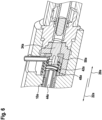
- the lithotripsy device has a coupling unit 30 (see Fig. 4 ).
- the coupling unit 30 is configured to couple the sonotrode 10 to the shock pulse unit 32.
- the coupling unit 30 has at least one transmission element 34.
- the transmission element 34 has at least a first active surface 36.
- the first active surface 36 is configured to receive a pulse. In an operating state, the projectile 62 strikes the active surface 36.
- the transmission element 34 has at least a second active surface 38.
- the second active surface 38 lies opposite the first active surface 36.
- the second active surface 38 is configured to at least indirectly transmit the received pulse to the sonotrode 10 along the second transmission direction 22.
- the transmission element 34 is mounted in a floating manner.
- the transmission element 34 is arranged with play between the sonotrode 14 and the projectile 62. It is conceivable that the transmission element could also be formed integrally with the sonotrode 10.
- the coupling unit 30 has a quick connector 40.
- the quick connector 40 is designed to establish and detach a mechanical connection between the shock pulse unit 32 and the sonotrode 10.
- the quick connector 40 is designed to establish a connection that can be released without the use of tools and without causing damage.
- the connection is a force-locking and/or positive-locking connection.
- the quick connector 40 forms the screw closure.
- other types of quick connectors are also conceivable, such as a bayonet closure or the like.
- the lithotripsy device has a fluid unit 42.
- the fluid unit 42 is configured to provide a fluid for rinsing and/or to discharge a fluid.
- the fluid unit 42 has at least one fluid channel 44.
- the fluid channel 44 is at least partially formed by the sonotrode 10.
- the sonotrode 10 has an axial recess which partially forms the fluid channel 44.
- the fluid channel 44 is at least partially formed by the coupling unit 30.
- the transmission element 34 has an axial recess which partially forms the fluid channel 44.
- the fluid channel 44 has at least one bend 46.
- the bend 46 of the fluid channel 44 is arranged in the region of the coupling unit 30.
- the bend 46 is integrated into the transmission element 34.
- the transmission element 34 has at least one radial opening. The radial opening establishes a connection to the axial recess of the transmission element 34.
- the lithotripsy device has at least one bearing unit 48.
- the bearing unit 48 is designed to move the sonotrode 10 along the first and/or second
- the bearing unit 48 is designed as a sliding bearing.
- the bearing unit 48 has at least one sealing element 50.
- the bearing unit 48 is formed by adjacent surfaces of the sonotrode 10 and/or the transmission element 34, as well as a guide channel 82 embedded in the housing 70.
- Figure 5 shows a schematic flow chart of an exemplary method for operating the lithotripsy device.
- the operation is an extracorporeal test operation.
- the method comprises a method step 100.
- the ultrasonic generator 74 is activated.
- the ultrasonic generator 74 generates ultrasonic waves.
- the ultrasonic waves are transmitted and focused by the ultrasonic horn 18 along the first transmission direction 20.
- the ultrasonic waves are received by the sonotrode head 12. From the sonotrode head 12, the ultrasonic waves are transmitted along a second transmission direction 22 to the sonotrode tip 14.
- the sonotrode tip 14 transmits the ultrasonic waves to any concretions, which can be destroyed as a result.
- the method comprises a method step 102.
- the shock pulse unit 32 is activated.
- the drive device 64 pneumatically accelerates the projectile 62.
- the projectile 62 strikes the transmission element 34. This largely stops the movement of the projectile 62 and transmits a shock pulse from the projectile 62 to the transmission element 34.
- the transmission element 34 is in contact with the sonotrode 10
- the sonotrode in turn transmits the shock pulse to the sonotrode head 12.
- the shock pulse is transmitted along the second transmission direction 22 from the sonotrode head 12 to the sonotrode tip 14.
- the sonotrode tip 14 in turn transmits the shock pulse to any concretions, which can be destroyed as a result.
- Process steps 100 and 102 can be performed in any order, either alternately or simultaneously. Especially when process steps 100 and 102 are performed simultaneously, a combined operation can be achieved, in which any concretions can be subjected to ultrasonic waves and shock pulses simultaneously.
- the lithotripsy device has at least one bearing unit 48a.
- the bearing unit 48a is configured to movably and floatingly support a sonotrode 10a of the lithotripsy device along a first and/or a second transmission direction 20a, 22a.
- the bearing unit 48a has at least one sealing element 50a, which at least partially delimits a fluid channel 44a of a fluid unit 42a of the lithotripsy device.
- the sealing element 50a is connected to the sonotrode 10a and a transmission element 34a of a coupling unit 30a of the lithotripsy device.
- the sealing element 50a is designed as a bellows.
- the sealing element 50a is connected to a sonotrode 10a and the transmission element 34a in a force-fitting and/or form-fitting manner.
Landscapes
- Health & Medical Sciences (AREA)
- Surgery (AREA)
- Engineering & Computer Science (AREA)
- Life Sciences & Earth Sciences (AREA)
- Biomedical Technology (AREA)
- Nuclear Medicine, Radiotherapy & Molecular Imaging (AREA)
- Vascular Medicine (AREA)
- Orthopedic Medicine & Surgery (AREA)
- Mechanical Engineering (AREA)
- Heart & Thoracic Surgery (AREA)
- Medical Informatics (AREA)
- Molecular Biology (AREA)
- Animal Behavior & Ethology (AREA)
- General Health & Medical Sciences (AREA)
- Public Health (AREA)
- Veterinary Medicine (AREA)
- Surgical Instruments (AREA)
Description
- Die Erfindung betrifft eine Lithotripsievorrichtung, insbesondere eine intrakorporale Lithotripsievorrichtung, nach dem Oberbegriff des Anspruchs 1 sowie ein Verfahren zum extrakorporalen Testbetrieb einer Lithotripsievorrichtung nach dem Oberbegriff des Anspruchs 19. Chirurgische oder therapeutische Verfahren werden nicht beansprucht.
- Aus dem Stand der Technik ist bereits eine Lithotripsievorrichtung bekannt, welche eine Sonotrode, welche einen Sonotrodenkopf und eine Sonotrodenspitze umfasst, und ein Ultraschallhorn aufweist. Das Ultraschallhorn ist dazu eingerichtet, entlang einer Übertragungsrichtung Ultraschallwellen auf den Sonotrodenkopf zu übertragen und zu fokussieren. Ferner ist die Sonotrode dazu eingerichtet, die Ultraschallwellen entlang derselben Übertragungsrichtung die Ultraschallwellen von dem Sonotrodenkopf zu der Sonotrodenspitze zu leiten.
-
EP 1 163 883 A1 beansprucht eine Vorrichtung zum Entfernen von Körpersteinen mit einem intrakorporalen Lithotripter, bei dem eine als Wellenleiter ausgebildete Metallsonde mittels eines elektrisch angesteuerten Ultraschallwandlers zur longitudinalen Schwingung angeregt und diese Schwingungsanregung auf eine mit einem reversibel angetriebenen Schlagteil gesteuerte Ausbildung einer Stoß- beziehungsweise Druckwelle in der Metallsonde umschaltbar ist. Hierbei werden die erzeugten Ultraschallschwingungen vom Horn des Ultraschallwandlers in distaler Richtung fokussiert und von der Metallsonde weiter in distaler Richtung bis zur Sondenspitze zum Entfernen von Körpersteinen übertragen. - In der
EP 1 163 882 A1 wird eine Vorrichtung zum Entfernen von Körpersteinen mit einem intrakorporalen Lithotripter beschrieben, bei dem eine Sonotrode mittels eines Ultraschallwandlers zur longitudinalen Schwingung anregbar ist und proximalseitig der hohlen Sonotrode eine axial fluchtende Führungshülse für ein reversibel angetriebenes Schlagteil angeordnet ist, welches auf einen Massekörper einer Stoßsonde einwirkbar ist, welche in dem Hohlraum der Sonotrode aufgenommen ist. Hierbei erfolgen die Schwingungsanregung und die Stoßanregung ebenfalls in dieselbe, distale Richtung. -
WO 2019/141822 A1 betrifft eine Vorrichtung zum Zertrümmern von Körpersteinen mit einer Sonde und einer Antriebseinheit zur Auslenkung der Sonde entlang ihrer Längserstreckung, wobei die Antriebseinheit eine erste Antriebseinrichtung zur periodischen Auslenkung der Sonde und eine zweite Antriebseinrichtung zur impulsförmigen Ausrichtung der Sonde aufweist, wobei die Übertragung der periodischen Auslenkung und der impulsförmigen Auslenkung beide in Richtung der Längsachse der Sonotrode zur Sonotrodenspitze erfolgt. - Die Aufgabe der Erfindung besteht insbesondere darin, eine gattungsgemäße Vorrichtung mit verbesserten Eigenschaften hinsichtlich einer Effizienz, insbesondere einer Bauraumeffizienz und/oder einer Bauteileffizienz bereitzustellen. Die Aufgabe wird erfindungsgemäß durch eine Vorrichtung mit den Merkmalen des Patentanspruchs 1 bzw. einem Verfahren mit den Merkmalen gemäß Patentanspruch 19 gelöst, während vorteilhaft Ausgestaltung und Weiterbildung der Erfindung den Unteransprüchen entnommen werden können.
- Die Erfindung geht aus von einer Lithotripsievorrichtung, insbesondere einer intrakorporalen Lithotripsievorrichtung, mit wenigstens einer Sonotrode, welche zur Aufnahme von Ultraschallwellen wenigstens einen Sonotrodenkopf und zur Beaufschlagung von Konkrementen wenigstens eine Sonotrodenspitze, welche mit dem Sonotrodenkopf verbunden ist, umfasst, und mit einem Ultraschallhorn.
- Es wird vorgeschlagen, dass das Ultraschallhorn dazu eingerichtet ist, entlang einer ersten Übertragungsrichtung Ultraschallwellen zumindest mittelbar auf den Sonotrodenkopf zu übertragen und zu fokussieren, und die Sonotrode dazu eingerichtet ist, entlang wenigstens einer zweiten Übertragungsrichtung, die von der ersten Übertragungsrichtung verschieden ist, die Ultraschallwellen vom Sonotrodenkopf zur Sonotrodenspitze zu übertragen.
- Hierdurch kann vorteilhaft eine Effizienz verbessert werden. Insbesondere kann eine kompakte Anordnung von Bauteilen realisiert werden, wodurch sich weitere Baugruppen und Komponenten eines Lithotripters, wie insbesondere eine Stoßimpulseinheit, zur kombinierten Lithotripsie einbinden lassen. Besonders vorteilhaft kann eine Energieübertragung von Energie, bereitstellenden Komponenten auf die Sonotrode verbessert werden, wie beispielsweise in Form von Ultraschallwellen und/oder Stoßimpulsen. Besonders vorteilhaft kann ein modularer Aufbau erzielt werden, welcher je nach Kombination bzw. Betrieb einzelner Module, sowohl den Einzelbetrieb nur mit Ultraschallwellen oder einen Kombinationsbetrieb mit Ultraschallwellen und Stoßimpulsen erlaubt. Dies kann insbesondere zur Beseitigung von besonders großen oder festen Konkrementen von Vorteil sein.
- Unter einer "Lithotripsievorrichtung" soll insbesondere ein vorzugsweise funktionsfähiger Bestandteil, beispielsweise einer Unterbaugruppe und/oder eine Konstruktions- und/oder eine Funktionskomponente eines Lithotripters verstanden werden. Vorzugsweise kann die Lithotripsievorrichtung den Lithotripter zumindest teilweise, bevorzugt zumindest zu einem Großteil und besonders bevorzugt vollständig ausbilden. Die Lithotripsievorrichtung ist insbesondere zu einer Zertrümmerung von Konkrementen eingerichtet. Unter "Konkrementen" sollen insbesondere sich in Körpern durch Abscheidung entstehende feste Gebilde verstanden werden, welche zumindest teilweise, vorzugsweise zumindest zu einem Großteil und besonders bevorzugt vollständig aus Salzen bestehen, wie beispielsweise Nierensteine, Gallensteine, Harnsteine, Speichelsteine oder dergleichen. Unter einer "intrakorporalen Lithotripsievorrichtung" soll insbesondere eine Lithotripsievorrichtung verstanden werden, welche dazu eingerichtet ist zumindest teilweise und vorzugsweise zumindest zu einem Großteil in eine insbesondere künstliche und/oder natürliche Öffnung, insbesondere Körperöffnung, eingeführt zu werden, um dort angesammelte Konkremente zu zertrümmern und/oder zu entfernen. Unter "eingerichtet" soll insbesondere speziell programmiert, vorgesehen, ausgelegt, ausgebildet und/oder ausgestattet verstanden werden. Darunter, dass ein Bauteil zu einer bestimmten Funktion eingerichtet ist, soll insbesondere verstanden werden, dass das Bauteil diese bestimmte Funktion in zumindest einen Anwendungs- und/oder Betriebszustand erfüllt und/oder ausführt. Unter dem Ausdruck "zumindest zu einem Großteil" soll dabei insbesondere dabei zumindest zu 55%, vorzugsweise zumindest zu 65%, bevorzugst zumindest zu 70% und besonders bevorzugt zumindest zu 85% und ganz besonders bevorzugt zumindest zu 95%, sowie vorteilhaft vollständig verstanden werden und zwar insbesondere mit Bezug auf ein Volumen und/oder eine Masse eines Bauteilts. Unter einer "Sonotrode" soll insbesondere eine stab-, röhren- und/oder schlauchförmige Sonde verstanden werden, welche zur Untersuchung und/oder Behandlung eingerichtet ist. Vorzugsweise ist die Sonotrode als eine intrakorporale Sonotrode ausgebildet. Unter einer "intrakorporalen Sonotrode" soll insbesondere eine Sonotrode verstanden werden, welche dazu eingerichtet ist, zumindest teilweise, vorzugsweise zumindest zu einem Großteil und besonders bevorzugt vollständig in eine insbesondere künstliche und/oder natürliche Öffnung, insbesondere Körperöffnung, eingeführt zu werden, um beispielsweise dort angesammelte Konkremente zu zertrümmern und/oder zu entfernen. Die Sonotrode weist insbesondere zumindest eine Sonotrodenspitze auf, welche dazu eingerichtet ist, Konkremente unmittelbar zu kontaktieren sowie Ultraschallwellen auf diese zu übertragen. Anstelle einer unmittelbaren Beaufschlagung kann auch eine zumindest mittelbare Beaufschlagung der Konkremente durch die Sonotrode denkbar sein. Unter "zumindest mittelbar" soll insbesondere indirekt, aber vorzugsweise auch direkt, also insbesondere unmittelbar, verstanden werden. Der Sonotrodenkopf und die Sonotrodenspitze der Sonotrode sind vorzugsweise voneinander separat ausgebildet. Alternativ könnten Sonotrodenkopf und Sonotrodenspitze einstückig ausgebildet und/oder verbunden sein. Darunter, dass "ein Bauteil und ein weiteres Bauteil zumindest teilweise einstückig ausgebildet und/oder verbunden sind", soll insbesondere verstanden werden, dass zumindest ein Element und/oder Teil des Bauteils und zumindest ein Element und/oder ein Teil des weiteren Bauteils einteilig miteinander ausgebildet und/oder verbunden sind. Unter "einstückig" soll insbesondere zumindest stoffschlüssig verbunden, wie beispielsweise durch einen Schweißprozess, einen Klebeprozess, einen Anspritzprozess und/oder einen anderen dem Fachmann als sinnvoll erscheinenden Prozess und/oder vorteilhaft in einem Stück geformt verstanden werden, wie beispielsweise durch eine Herstellung aus einem Guss und/oder durch eine Herstellung in einem Ein- oder Mehrkomponentenspritzverfahren und vorteilhaft aus einem einzelnen Rohling. Die Lithotripsievorrichtung weist insbesondere wenigstens einen Ultraschallgenerator auf. Der Ultraschallgenerator ist dazu eingerichtet, die Ultraschallwellen bereitzustellen und/oder zu erzeugen. Zur Erzeugung der Ultraschallwellen weist der Ultraschallgenerator wenigstens einen, vorzugsweise zumindest zwei, besonders bevorzugst zumindest drei und ganz besonders bevorzugt eine Vielzahl von Ultraschallaktoren auf. Der Ultraschallaktor ist vorzugsweise als ein Piezoaktor ausgebildet. Es sind jedoch auch andere, insbesondere mechanische Ausgestaltungen des Ultraschallaktors denkbar. Insbesondere für den Fall, dass der Ultraschallgenerator zumindest zwei Ultraschallaktoren umfasst, liegen diese zumindest mittelbar aneinander an, um vorteilhaft eine Intensität der erzeugten Ultraschallwellen zu erhöhen. Der Ultraschallgenerator ist insbesondere mit dem Ultraschallhorn wirkverbunden. Vorzugseise liegt das Ultraschallhorn zumindest mittelbar an dem Ultraschallgenerator an. Bevorzugt besteht das Ultraschallhorn zumindest teilweise, vorzugsweise zumindest zu einem Großteil und besonders bevorzugt vollständig aus Metall, wie beispielsweise Eisen, Titan, Stahl oder einer Metalllegion. Unter "Ultraschallwellen" sollen insbesondere Schallwellen verstanden werden, welche oberhalb eines für den Menschen wahrnehmbaren Hörfrequenzbereichs liegen. Im vorliegenden Fall weisen die Ultraschallwelle insbesondere eine Ultraschallfrequenz von zumindest 10 kHz, vorzugsweise zumindest 15 kHz und besonders bevorzugt von zumindest 20 kHz und/oder von höchstens 100 kHz, vorzugsweise von höchstens 80 kHz und besonders bevorzugt von höchstens 56 kHz auf. Ganz besonders bevorzugt beträgt die Ultraschallfrequenz der Ultraschallwellen einen Wert zwischen 22 kHz und 55 kHz. Unter einer "Übertragungsrichtung" soll insbesondere eine Richtung verstanden werden, welche eine Übertragung von Ultraschallwellen entlang eines Bauteils entspricht. Insbesondere ist die erste Übertragungsrichtung zumindest im Wesentlichen parallel zu einer Haupterstreckungsrichtung des Ultraschallhorn. Ferner ist insbesondere die zweite Übertragungsrichtung zumindest im Wesentlichen parallel zu einer Haupterstreckungsrichtung der Sonotrode. Unter einer "Haupterstreckungsrichtung" eines Bauteils soll dabei insbesondere eine Richtung verstanden werden, welche parallel zu einer längsten Kante eines kleinsten gedachten Quaders verläuft, welcher das Bauteil gerade noch vollständig umschließt. Unter "zumindest im Wesentlichen parallel" soll insbesondere das Einschließen eines Winkels von 0°verstanden werden, wobei insbesondere dieser Winkel eine Abweichung von höchstens 15°, vorzugsweise von höchstens 10° und besonders bevorzug von höchstens 5° aufweisen kann.
- Es ist denkbar, dass die erste Übertragungsrichtung und die zweite Übertragungsrichtung winklig zueinander sind, um beispielsweise einen Schereffekt bei der Beaufschlagung der Konkremente zu erzeugen, wodurch vorteilhaft eine Zerstörung der Konkremente verbessert werden kann. Des Weiteren wird vorgeschlagen, dass die erste Übertragungsrichtung und die zweite Übertragungsrichtung einander entgegengerichtet sind. Hierdurch kann eine Kompaktheit weiter verbessert werden. Vorzugsweise sind die erste Übertragungsrichtung und die zweite Übertragungsrichtung zueinander antiparallel. Die erste Übertragungsrichtung ist insbesondere eine proximale Richtung. Unter einer "proximalen Richtung" soll insbesondere eine Richtung verstanden werden, welche in Richtung eines Benutzers der Vorrichtung ausgerichtet ist. Die zweite Übertragungsrichtung ist insbesondere eine distale Richtung. Unter einer "distalen Richtung" soll insbesondere eine Richtung verstanden werden, welche in Richtung eines zu behandelnden Patienten ausgerichtet ist.
- Es wird zudem vorgeschlagen, dass das Ultraschallhorn sich entlang der ersten Übertragungsrichtung verjüngt. Hierdurch kann vorteilhaft eine Kompaktheit weiter verbessert werden, da derart das Ultraschallhorn weniger Bauraum innerhalb eines Gehäuses benötigt. Auch können hierdurch Ultraschallwellen besser fokussiert werden. Das Ultraschallhorn weist vorzugsweise eine sich insbesondere konkav verjüngende Zylinderform auf.
- Um vorteilhaft einen Bauraum weiter zu verringern wird vorgeschlagen, dass das Ultraschallhorn die Sonotrode koaxial umgebend angeordnet ist. Darunter, dass "zwei Bauteile koaxial angeordnet sind", soll insbesondere verstanden werden, dass beide Bauteile eine identische Haupterstreckungsachse aufweisen. Die Sonotrode weist einen Außendurchmesser auf, welcher im Wesentlichen kleiner ist als ein Außendurchmesser des Ultraschallhorns. Unter dem Ausdruck "im Wesentlichen kleiner" soll insbesondere verstanden werden wenigstens um 10% kleiner, vorzugsweise um wenigstens 20% kleiner und besonders bevorzugt um wenigstens 30% kleiner.
- In einer Ausgestaltung der Erfindung wird vorgeschlagen, dass die Sonotrode das Ultraschallhorn entlang der zweiten Übertragungsrichtung durchstößt. Hierdurch kann vorteilhaft ein Bauraum weiter reduziert werden. Das Ultraschallhorn weist insbesondere eine zu der Sonotrode korrespondierend ausgebildete Ausnehmung auf, innerhalb welcher die Sonotrode zumindest teilweise angeordnet ist.
- Um eine effiziente Energieübertragung zu gewährleisten und trotzdem wenig Bauraum, insbesondere innerhalb eines Gehäuses der Lithotripsievorrichtung, zu beanspruchen, wird des Weiteren vorgeschlagen, dass eine Haupterstreckung der Sonotrode größer ist als eine Haupterstreckung des Ultraschallhorns. Insbesondere ragt ein Teil der Sonotrode distalseitig über das Ultraschallhorn hinaus. Besonders bevorzugt ragt die Ultraschallspitze über das Ultraschallhorn hinaus. Insbesondere liegt der Sonotrodenkopf innerhalb eines Bereichs des Ultraschallhorns. Die Haupterstreckung der Sonotrode ist insbesondere zumindest um 15%, vorzugsweise zumindest um 30% und besonders bevorzugt zumindest um 45% größer als eine Haupterstreckung des Ultraschallhorns.
- Des Weiteren wird vorgeschlagen, dass die Lithotripsievorrichtung eine Koppeleinheit umfasst, welche zu einer Beaufschlagung der Sonotrode dazu eingerichtet ist, die Sonotrode mit einer Stoßimpulseinheit zu koppeln. Es kann vorteilhaft ein modularer Aufbau erzielt werden, wobei insbesondere verschiedene Komponenten der Lithotripsievorrichtung abhängig von einer Betriebsart miteinander koppelbar sind. Unter einer "Koppeleinheit" soll insbesondere eine Einheit verstanden werden, welche dazu eingerichtet ist, zumindest zwei weitere Bauteile miteinander wirkverbunden zu koppeln. Dazu kann die Koppeleinheit zu einer form- und/oder kraftschlüssigen Verbindung eingerichtet sein. Insbesondere weist die Lithotripsievorrichtung die Stoßimpulseinheit auf. Unter einer "Stoßimpulseinheit" soll insbesondere eine Einheit verstanden werden, welche zur Bereitstellung von Stoßimpulsen wenigstens ein beweglich gelagertes Projektil umfasst, welches dazu eingerichtet ist, die Sonotrode zumindest mittelbar mit Stoßimpulsen zu beaufschlagen. Die Stoßimpulseinheit ist insbesondere dazu eingerichtet, das Projektil mechanisch, pneumatisch, hydraulisch und/oder elektromagnetisch zu beschleunigen, wobei vorzugsweise das Projektil sein durch die Beschleunigung erfahrenen Impuls zumindest teilweise, vorzugsweise zu einem Großteil und besonders bevorzugt vollständig als Stoßimpuls auf die Sonotrode überträgt.
- Um eine bauteileffiziente Kopplung zu erzielen wird insbesondere vorgeschlagen, dass die Koppeleinheit zumindest ein Übertragungselement aufweist, welches zumindest eine erste Wirkfläche aufweist, die dazu eingerichtet ist, einen Impuls aufzunehmen und wenigstens eine zweite Wirkfläche aufweist, welche dazu eingerichtet ist, den aufgenommenen Impuls auf die Sonotrode entlang der zweiten Übertragungsrichtung zumindest mittelbar zu übertragen. Die erste Wirkfläche ist insbesondere eine proximale Wirkfläche. Die erste Wirkfläche zeigt vorzugsweise in Richtung der ersten Übertragungsrichtung. Die erste Wirkfläche ist insbesondere dazu eingerichtet, einen Stoßimpuls zumindest mittelbar von der Stoßimpulseinheit aufzunehmen und zwar insbesondere von dem Projektil der Stoßimpulseinheit. Insbesondere ist die zweite Wirkfläche eine distale Wirkfläche. Die zweite Wirkfläche zeigt vorzugsweise in Richtung der zweiten Übertragungsrichtung. Die zweite Wirkfläche ist insbesondere dazu eingerichtet, einen Stoßimpuls zumindest mittelbar auf die Sonotrode und zwar insbesondere den Sonotrodenkopf zu übertragen. Die erste Wirkfläche und die zweite Wirkfläche sind zueinander, vorzugsweise entgegengesetzt ausgerichtet. Das Übertragungselement ist insbesondere separat von der Sonotrode ausgebildet. Alternativ ist es denkbar, dass das Übertragungselement zumindest teilweise einstückig mit der Sonotrode ausgebildet ist. Beispielsweise könnte das Übertragungselement einstückig mit dem Sonotrodenkopf ausgebildet sein. Das Übertragungselement ist insbesondere zwischen dem Sonotrodenkopf und dem Projektil der Stoßimpulseinheit angeordnet. Besonders bevorzugt ist das Übertragungselement als ein Bolzen ausgebildet.
- Weiterhin wird vorgeschlagen, dass die Koppeleinheit einen Schnellverbinder umfasst, welcher zu einer herstell- und/oder lösbaren mechanischen Verbindung der Stoßimpulseinheit mit der Sonotrode eingerichtet ist. Hierdurch kann vorteilhaft eine Kopplung zwischen Stoßimpulseinheit und der Sonotrode vereinfacht werden. Unter einem "Schnellverbinder" soll insbesondere eine Einheit verstanden werden, welche zu einer einfachen und/oder schnellen, vorzugsweise werkzeuglosen und/oder einhändigen Herstellung und/oder Aufhebung einer Verbindung zumindest zwei der Bauteile eingerichtet ist. Der Schnellverbinder kann insbesondere einen Schnellspanner und vorzugsweise einen Bajonettverschluss umfassen. Ferner ist der Schnellverbinder zu einer austauschbaren Verbindung von Bauteilen vorgesehen. Unter einer "austauschbaren Verbindung" soll insbesondere eine Verbindung zwischen einem ersten Bauteil und einem zweiten Bauteil verstanden werden, wobei das erste Bauteil gegen zumindest ein weiteres zusätzliches Bauteil ausgetauscht werden kann, welches insbesondere an Stelle des ersten Bauteils mit dem zweiten Bauteil verbindbar ist. Beispielsweise ist denkbar, dass verschieden ausgebildete Stoßimpulseinheiten mit der Sonotrode koppelbar sind. Beispielsweise könnte man eine pneumatische Stoßimpulseinheit, eine mechanische Stoßimpulseinheit, eine elektromagnetische Stoßimpulseinheit und/oder eine hydraulische Stoßimpulseinheit variabel verbunden werden, um Stoßimpulse auf die Sonotrode zu übertragen.
- Ferner wird vorgeschlagen, dass die Lithotripsievorrichtung eine Fluideinheit umfasst, die wenigstens einen Fluidkanal umfasst, welcher wenigstens teilweise von der Sonotrode ausgebildet ist und wenigstens eine Abwinklung aufweist. Unter einem "Fluidkanal" soll insbesondere eine Baueinheit verstanden werden, die zumindest teilweise zu einer Führung eines Fluidstroms vorgesehen ist und die den Fluidstrom, in einer Hauptströmungsrichtung betrachtet, unmittelbar zumindest teilweise, vorzugsweise auf drei Seiten und besonders vorteilhaft vollständig umschließt. Vorzugsweise ist eine Erstreckung des Fluidkanals entlang der Hauptströmungsrichtung des Fluidstroms zumindest 1-mal, insbesondere wenigstens 3-mal und vorteilhaft zumindest 5-mal so lang wie wenigstens eine Querschnittserstreckung an einem Punkt des Fluidkanals senkrecht zu der Hauptströmungsrichtung des Fluidstroms an dem Punkt. Unter einem "Fluid" soll in diesem Zusammenhang insbesondere eine Flüssigkeit, vorzugsweise Wasser, ein Gas und/oder ein Gas-Flüssigkeits-Gemisch verstanden werden. Unter einer "Abwinklung" soll insbesondere ein Zwischenabschnitt des Fluidkanals verstanden werden, entlang dessen eine Hauptströmungsrichtung des Fluidkanals variiert. Vorzugsweise bildet der Zwischenabschnitt zumindest eine Biegung oder einen Knick aus. Insbesondere weist der Fluidkanal zumindest einen ersten Teilabschnitt und zumindest einen zweiten Teilabschnitt auf, welche insbesondere zueinander winklig ausgerichtet sind. Insbesondere ist der Zwischenabschnitt vorzugsweise unmittelbar zwischen dem ersten Teilabschnitt und dem zweiten Teilabschnitt angeordnet. Vorteilhaft weist der erste Teilabschnitt eine erste Haupterstreckungsrichtung und/oder eine erste Hauptströmungsrichtung auf und der zweite Teilabschnitt weist zumindest eine zweite Haupterstreckungsrichtung und/oder zumindest eine zweite Hauptströmungsrichtung auf, wobei die erste Haupterstreckungsrichtung und/oder die erste Hauptströmungsrichtung winklig zur zweiten Haupterstreckungsrichtung und/oder zur zweiten Hauptströmungsrichtung ausgerichtet ist. Unter "winklig ausgerichtet" soll in diesem Zusammenhang insbesondere von parallel und/oder antiparallel verschieden ausgerichtet verstanden werden. Vorzugsweise schließt der erste Teilabschnitt, insbesondere die erste Haupterstreckungsrichtung und/oder die erste Hauptströmungsrichtung, mit dem zweiten Teilabschnitt, insbesondere der zweiten Haupterstreckungsrichtung und/oder der zweiten Hauptströmungsrichtung, des Fluidkanals zumindest einen Winkel von zumindest 45°, insbesondere von zumindest 60°, vorteilhaft von zumindest 75° und besonders bevorzugt von zumindest im Wesentlichen 90° ein. Unter einem Winkel von "zumindest im Wesentlichen 90" soll insbesondere ein Winkel von
90° insbesondere mit einer Abweichung von höchstens 8°, vorzugsweise von höchstens 5° und besonders bevorzugt von höchstens 2° verstanden werden. Insbesondere sind die erste Haupterstreckungsrichtung und/oder die erste Hauptströmungsrichtung zumindest im Wesentlichen parallel zu der Haupterstreckungsrichtung der Sonotrode. Insbesondere sind die zweite Haupterstreckungsrichtung und/oder die zweite Hauptströmungsrichtung zumindest im Wesentlichen senkrecht zu der Haupterstreckungsrichtung der Sonotrode. - Des Weiteren wird vorgeschlagen, dass der Fluidkanal zumindest teilweise von der Koppeleinheit ausgebildet ist. Es kann vorteilhaft ein Bauraum eingespart werden. Insbesondere ist die Abwinklung des Fluidkanals im Bereich der Koppeleinheit angeordnet ist. Vorzugsweise ist die Abwinklung in das Übertragungselement der Koppeleinheit integriert. Das Übertragungselement weist insbesondere eine Ausnehmung auf, welche die Abwinklung ausbildet.
- Zudem vorgeschlagen, dass die Lithotripsievorrichtung wenigstens eine Lagereinheit umfasst, welche dazu eingerichtet ist, die Sonotrode und/oder das Übertragungselement beweglich entlang der ersten und/oder zweiten Übertragungsrichtung schwimmend zu lagern. Es kann vorteilhaft ein Eintrag von Stoßimpulsen in die Sonotrode verbessert werden. Die Lagereinheit ist insbesondere als ein Gleitlager ausgebildet. Die Lagereinheit ist insbesondere von aneinander liegenden Oberflächen der Sonotrode und/oder das Übertragungselement sowie eines in das Gehäuse eingelassenen Führungskanal gebildet.
- Es wird zudem vorgeschlagen, dass die Lagereinheit zumindest ein Dichtelement umfasst, welches wenigstens teilweise den Fluidkanal begrenzt. Es kann vorteilhaft weitere Bauteile eingespart werden.
- Ferner wird vorgeschlagen, dass das Dichtelement mit der Sonotrode und dem Übertragungselement verbunden ist. Es kann vorteilhaft weitere Bauteile welche zu einer Abdichtung sowohl der Sonotrode als auch des Übertragungselement notwendig wären eingespart werden. Vorzugsweise ist das Dichtelement kraft- und/oder formschlüssig mit der Sonotrode und dem Übertragungselement verbunden.
- Das Dichtelement könnte beispielsweise als ein O-Ring ausgebildet sein. In einer offenbarungsgemäßen Ausgestaltung wird vorgeschlagen, dass das Dichtelement als ein Faltenbalg ausgebildet ist. Es kann vorteilhaft weitere Bauteile eingespart werden
- Ein weiterer Aspekt der Erfindung geht aus von einem Verfahren zum Betrieb einer Lithotripsievorrichtung, wie beispielsweise zu einem vorzugsweise extrakorporalen Testbetrieb einer Lithotripsievorrichtung, insbesondere einer solchen Lithotripsievorrichtung, bei welchem Ultraschallwellen von einem Sonotrodenkopf einer Sonotrode aufgenommen wird und Konkrementen von wenigstens einer Sonotrodenspitze der Sonotrode, welche mit dem Sonotrodenkopf verbunden ist, beaufschlagt werden und die Ultraschallwellen von einem Ultraschallhorn weitergeleitet werden.
- Es wird vorgeschlagen, dass das Ultraschallhorn die Ultraschallwellen entlang einer ersten Übertragungsrichtung zumindest mittelbar auf den Sonotrodenkopf überträgt und fokussiert und die Sonotrode entlang wenigstens einer zweiten Übertragungsrichtung, die von der ersten Übertragungsrichtung verschieden ist, die Ultraschallwellen vom Sonotrodenkopf zur Sonotrodenspitze überträgt.
- Hierdurch kann vorteilhaft eine Effizienz verbessert werden. Insbesondere kann eine kompakte Anordnung von Bauteilen realisiert werden, wodurch sich weitere Baugruppen und Komponenten eines Lithotripters, wie insbesondere eine Stoßimpulseinheit, zur kombinierten Lithotripsie einbinden lassen.
- Weitere Vorteile ergeben sich aus der folgenden Zeichnungsbeschreibung. In den Zeichnungen ist ein Ausführungsbeispiel der Erfindung dargestellt. Die Zeichnungen, die Beschreibung und die Ansprüche enthalten zahlreiche Merkmale in Kombination. Der Fachmann wird die Merkmale zweckmäßigerweise auch einzeln betrachten und zu sinnvollen weiteren Kombinationen zusammenfassen.
- Es zeigen:
- Fig. 1
- eine schematische Darstellung eines Lithotripsiesystems mit einer Lithotripsievorrichtung in einer perspektivischen Ansicht,
- Fig. 2
- eine schematische Darstellung eines Teils der Lithotripsievorrichtung in einer perspektivischen Ansicht,
- Fig. 3
- eine schematische Darstellung eines Teils der Lithotripsievorrichtung in einer Schnittansicht,
- Fig. 4
- eine schematische Darstellung eines Teils der Lithotripsievorrichtung mit einer Koppeleinheit in einer Schnittansicht,
- Fig. 5
- einen schematischen Ablaufplan eines beispielhaften Verfahrens zum Betrieb der Lithotripsievorrichtung und
- Fig. 6
- eine schematische Darstellung einer alternativen Ausgestaltung einer Lithotripsievorrichtung mit einer alternativen Lithotripsievorrichtung.
-
Fig. 1 zeigt eine schematische Darstellung eines Lithotripsiesystems 54 in einer perspektivischen Ansicht. Das Lithotripsiesystem 54 weist wenigstens einen Lithotripter 52 auf. Der Lithotripter 52 ist im vorliegenden Fall als ein intrakorporaler Lithotripter 52 ausgebildet. Alternativ könnte ein Lithotripter auch als ein extrakorporaler Lithotripter ausgebildet sein. - Der Lithotripter 52 weist wenigstens eine Lithotripsievorrichtung auf. Im vorliegenden Fall bildet die Lithotripsievorrichtung den Lithotripter 52 vollständig aus. Alternativ könnte die Lithotripsievorrichtung nur einen Teil eines Lithotripters ausbilden.
- Das Lithotripsiesystem 54 weist wenigstens ein Steuergerät 56 auf. Das Steuergerät 56 ist zumindest zu einer Steuerung der Lithotripsievorrichtung eingerichtet. Die Lithotripsievorrichtung ist mit dem Steuergerät 56 verbunden. Das Steuergerät 56 besitzt zumindest eine Steuerelektronik (nicht dargestellt). Zu einer Ansteuerung der Lithotripsievorrichtung ist die Steuerelektronik elektrisch und/oder elektronisch mit dieser verbunden. Die Steuerelektronik enthält zumindest einen Prozessor. Ferner enthält die Steuerelektronik wenigstens einen Speicher. Auf dem Speicher ist ein Betriebsprogramm hinterlegt. Das Betriebsprogramm ist von dem Prozessor ausführbar.
- Das Lithotripsiesystem 54 weist wenigstens ein Betätigungsmittel 58 auf. Das Betätigungsmittel 58 ist zu einer Aktivierung und/oder Deaktivierung der Lithotripsievorrichtung ausgebildet. Das Betätigungsmittel 58 ist mit dem Steuergerät 56 und zwar insbesondere mit der Steuerelektronik des Steuergeräts 56 verbunden. Im vorliegenden Fall ist das Betätigungsmittel 58 als ein Fußschalter ausgebildet. Alternativ könnte ein Betätigungsmittel auch als ein anderer elektrischer und/oder elektronischer Schalter ausgebildet sein, wie beispielsweise als ein Druckknopf, einen Kippschalter oder dergleichen, welcher insbesondere Teil einer Lithotripsievorrichtung sein könnte. Auch könnte eine Bedienung der Lithotripsievorrichtung über ein externes Gerät, insbesondere ein Handgerät, wie beispielsweise ein Tablet, ein Smartphone, eine Smartwatch oder dergleichen erfolgen.
- Das Lithotripsiesystem 54 weist ferner eine Fördereinrichtung 60 auf. Die Fördereinrichtung 60 ist im vorliegenden Fall als eine Pumpe ausgebildet. Die Fördereinrichtung 60 ist zur Förderung eines Irrigats eingerichtet. Dazu ist die Fördereinrichtung 60 fluidtechnisch mit der Lithotripsievorrichtung verbunden. Die Fördereinrichtung 60 dient zum Absaugen eines Irrigats und/oder zu einem Freispulen mittels eines Irrigats bei einem Lithotripsievorgang. Bei dem Irrigat kann es sich um eine Flüssigkeit handeln, wie in etwa eine Kochsalzlösung. Beispielsweise können mit dem Irrigat Bruchteile eines bei einem Lithotripsievorgang zerstörten Konkrements abtransportiert werden.
- Zur Erzeugung von Stoßimpulsen, wie beispielsweise mittels eines Projektils 62, der Lithotripsievorrichtung ist wenigstens eine Antriebseinrichtung 64 vorgesehen (vgl.
Fig. 2 und3 ). Die Antriebseinrichtung 64 ist im vorliegenden Fall separat von der Lithotripsievorrichtung ausgebildet. Die Antriebseinrichtung 64 ist Teil des Lithotripsiesystems 54. Die Antriebseinrichtung 64 ist Teil des Steuergeräts 56. Die Antriebseinrichtung 64 ist im vorliegenden Fall als eine pneumatische Antriebseinrichtung 64 ausgebildet. Die Antriebseinrichtung 64 ist als ein Druckluftgenerator ausgebildet. Alternativ könnte es sich bei der Antriebseinrichtung um eine mechanische, elektromagnetische oder eine hydraulische Antriebseinrichtung handeln. Alternativ könnte eine solche Antriebseinrichtung auch Teil einer solchen Lithotripsievorrichtung sein, beispielsweise, wenn diese Antriebseinrichtung als eine elektromagnetische Antriebseinheit, wie in etwa ein linearer Aktor. Auch könnte eine Antriebeinrichtung ein von einem Steuergerät separates Antriebsgerät ausbilden. - Die Lithotripsievorrichtung besitzt einen proximalen Abschnitt 66. Der proximale Abschnitt 66 ist bei einer Bedienung einem Bediener der Lithotripsievorrichtung zugewandt. Der proximale Abschnitt 66 ist bei einer Bedienung einem Patienten abgewandt. Der proximale Abschnitt 66 liegt bei einer Behandlung eines Patienten außerhalb des Patienten. Ferner besitzt die Lithotripsievorrichtung einen distalen Abschnitt 68. Der distale Abschnitt 68 ist bei einer Bedienung einem Bediener der Lithotripsievorrichtung abgewandt. Der distale Abschnitt 68 ist bei einer Bedienung einem Patienten zugewandt. Der distale Abschnitt 68 liegt bei einer Behandlung eines Patienten zumindest teilweise innerhalb des Patienten.
- Die Lithotripsievorrichtung weist ein Gehäuse 70 auf. Das Gehäuse 70 ist hohlzylinderförmig. Das Gehäuse 70 bildet zumindest teilweise den proximalen Abschnitt 66 der Lithotripsievorrichtung aus. Das Gehäuse 70 dient zur Anordnung weiterer Komponenten der Lithotripsievorrichtung.
- Ferner weist die Lithotripsievorrichtung eine Handhabe 72 auf. Die Handhabe 72 ist zu einer manuellen Bedienung der Lithotripsievorrichtung ausgebildet. Die Handhabe 72 ist von dem Gehäuse 70 ausgebildet. Die Handhabe 72 bildet zumindest teilweise den proximalen Abschnitt 66a aus. Alternativ könnte insbesondere bei einer robotischen Ansteuerung einer solchen Lithotripsievorrichtung auch auf eine Handhabe verzichtet werden oder zu einer Anbindung an einen Roboterarm genutzt werden.
-
Fig. 2 zeigt eine schematische Darstellung eines Teils der Lithotripsievorrichtung in einer perspektivischen Ansicht undFig. 3 in einer Schnittansicht. - Die Lithotripsievorrichtung weist wenigstens einen Ultraschallgenerator 74 auf. Der Ultraschallgenerator 74 ist dazu ausgebildet, Ultraschallwellen bereitzustellen. Zu einer Ansteuerung ist der Ultraschallgenerator 74 mit dem Steuergerät 56 und zwar insbesondere der Steuerelektronik verbunden. Der Ultraschallgenerator 74 ist zumindest teilweise in dem Gehäuse 70 angeordnet. Im vorliegenden Fall ist der Ultraschallgenerator 74 vollständig in dem Gehäuse 70 angeordnet. Der Ultraschallgenerator 74 bildet zumindest teilweise den proximalen Abschnitt 66 der Lithotripsievorrichtung aus.
- Der Ultraschallgenerator 74 enthält wenigstens einen Ultraschallaktor 76. Im vorliegenden Fall weist der Ultraschallgenerator 74 mehrere Ultraschallaktoren 76 auf. Der Ultraschallgenerator 74 weist zwei Ultraschallaktoren 76 auf. Die Ultraschallaktoren 76 sind aneinander anliegend gestapelt angeordnet. Der Übersichtlichkeit halber ist in den Zeichnungen nur ein Ultraschallaktor 76 mit einem Bezugszeichen versehen. Die Ultraschallaktoren 76 sind zumindest im Wesentlichen identisch zueinander ausgebildet. Im Folgenden ist nur ein Ultraschallaktor 76 näher beschrieben. Diese Beschreibung ist auch auf die weiteren Ultraschallaktoren 76 übertragbar. Im vorliegenden Fall ist der Ultraschallaktor 76 als ein Piezoaktor ausgebildet. Der Ultraschallaktor 76 ist zylinderplattenförmig ausgebildet. Der Übersichtlichkeit halber sind etwaige Anschluss- und/oder Kontaktierungsmittel und/oder Isolationen der Ultraschallaktoren 76 nicht in der
Fig. 2 bzw. 3 dargestellt. - Ferner weist die Lithotripsievorrichtung wenigstens ein Ultraschallhorn 18 auf. Das Ultraschallhorn 18 nimmt die von dem Ultraschallgenerator 74 bereitgestellten Ultraschallwellen auf. Das Ultraschallhorn 18 ist zur Übertragung von Ultraschallwellen ausgebildet. Das Ultraschallhorn 18 liegt an dem Ultraschallaktor 76 an.
- Das Ultraschallhorn 18 ist zumindest teilweise in dem Gehäuse 70 angeordnet. Das Ultraschallhorn 18 bildet zumindest teilweise den proximalen Abschnitt 66 der Lithotripsievorrichtung aus. Das Ultraschallhorn 18 ist zumindest teilweise außerhalb des Gehäuse 70 angeordnet. Das Ultraschallhorn 18 weist die Form eines Rotationskörpers auf. Im vorliegenden Fall weist das Ultraschallhorn 18 eine hohlzylinderartige Form auf. Das Ultraschallhorn 18 ist zumindest teilweise aus Metall, insbesondere Stahl oder Titan ausgebildet. Der Ultraschallgenerator 74 liegt an dem Ultraschallhorn 18 an.
- Das Ultraschallhorn 18 verjüngt sich entlang der ersten Übertragungsrichtung 20. Das Ultraschallhorn 18 weist eine Verjüngung auf. Die Verjüngung liegt innerhalb des Gehäuses 70. Die Verjüngung ist frei von Stufen. Die Verjüngung weist einen stetigen Verlauf auf. Der Verlauf der Verjüngung ist konkav. Der Verlauf der Verjüngung ist exponentiell. Alternativ oder zusätzlich könnte die Verjüngung auch stufenförmig oder katenoidalförmig sein. Das Ultraschallhorn 18 weist eine Ausnehmung 80 auf. Die Ausnehmung 80 verläuft koaxial entlang einer Rotationsachse des Ultraschallhorns 18.
- Die Lithotripsievorrichtung weist wenigstens eine Sonotrode 10 auf. Die Sonotrode 10 weist eine Haupterstreckung 26 auf. Die Sonotrode 10 ist zumindest teilweise außerhalb des Gehäuse 70 angeordnet. Die Sonotrode 10 bildet zumindest zu einem Großteil den distalen Abschnitt 68 der Lithotripsievorrichtung aus. Die Sonotrode 10 ist rohrförmig ausgebildet. Die Sonotrode 10 ist starr ausgebildet. Die Sonotrode 10 besteht zumindest teilweise aus Metall, insbesondere Stahl. Zur Aufnahme von Ultraschallwellen weist die Sonotrode 10 wenigstens einen Sonotrodenkopf 12 auf. Der Sonotrodenkopf 12 bildet zumindest teilweise ein proximales End der Sonotrode 10 aus. Zur Beaufschlagung von Konkrementen weist die Sonotrode 10 wenigstens eine Sonotrodenspitze 14 auf. Die Sonotrodenspitze 14 bildet zumindest teilweise ein distales Ende der Sonotrode 10 aus. Die Sonotrodenspitze 14 ist mit dem Sonotrodenkopf 12 verbunden.
- Die Sonotrode 10 ist zumindest teilweise in/an dem Ultraschallhorn 18 angeordnet. Die Sonotrode 10 ist von dem Ultraschallhorn 18 umgeben. Das Ultraschallhorn 18 ist die Sonotrode 10 koaxial umgebend angeordnet. Die Sonotrode 10 ist in der Ausnehmung 80 des Ultraschallhorns 18 angeordnet. Die Sonotrode 10 weist eine Haupterstreckung 26 auf. Das Ultraschallhorn 18 weist eine Haupterstreckung 28 auf. Die Haupterstreckung 26 der Sonotrode 10 ist größer als die Haupterstreckung 28 des Ultraschallhorns 18. Die Sonotrode 10 und die Ultraschallaktoren 76 sind so zueinander angeordnet, dass die Haupterstreckung 28 des Ultraschallhorn 18 vollständig innerhalb der Haupterstreckung 26 der Sonotrode 10 liegt.
- Das Ultraschallhorn 18 ist dazu eingerichtet, entlang einer ersten Übertragungsrichtung 20 Ultraschallwellen zumindest mittelbar auf einen Sonotrodenkopf 12 der Sonotrode 10 zu übertragen und zu fokussieren. Die erste Übertragungsrichtung 20 entspricht einer proximalen Richtung. Die Sonotrode 10a ist mit dem Ultraschallhorn 18 verbunden. Der Sonotrodenkopf 12 ist mit dem Ultraschallhorn 18 verbunden. Die Sonotrode 10 und das Ultraschallhorn 18 sind im vorliegenden Fall miteinander verschraubt. Alternativ oder zusätzlich kann die Sonotrode mit dem Ultraschallhorn verklebt oder verlötet sein. Ferner ist denkbar, dass eine solche Sonotrode mit solch einem Ultraschallhorn einstückig ausgebildet sein könnte.
- Die Sonotrode 10 ist dazu eingerichtet, entlang wenigstens einer zweiten Übertragungsrichtung 22, die von der ersten Übertragungsrichtung 20 verschieden ist, die Ultraschallwellen vom Sonotrodenkopf 12 zur Sonotrodenspitze 14 zu übertragen. Die zweite Übertragungsrichtung 22 entspricht einer distalen Richtung. Die erste Übertragungsrichtung 20 und die zweite Übertragungsrichtung 22 sind einander entgegengerichtet. Die Sonotrode 10 durchstößt das Ultraschallhorn 18 entlang der zweiten Übertragungsrichtung 22. Die Sonotrode 10 ragt proximalseitig aus dem Ultraschallhorn 18 heraus. Ferner ragt sie Sonotrode 10 distalseitig aus den Ultraschallwellen heraus.
- Zusätzlich zu einer Behandlung mit Ultraschallwellen ist die Lithotripsievorrichtung dazu eingerichtet, Stoßimpulse auf Konkremente zu übertragen. Dazu weist die Lithotripsievorrichtung eine Stoßimpulseinheit 32 auf. Die Stoßimpulseinheit 32 wenigstens ein Projektil 62 auf. Das Projektil 62 ist linear beweglich gelagert. In wenigstens einem Betriebszustand ist das Projektil 62 dazu ausgebildet, die Sonotrode 10 und/oder das Ultraschallhorn 18 zumindest mittelbar zu beaufschlagen. Im vorliegenden Fall beaufschlagt das Projektil 62 die Sonotrode 10 mittelbar. Zur Lagerung des Projektils 62 weist die Stoßimpulseinheit 32 wenigstens einen Führungskanal 82 auf. Die Lithotripsievorrichtung weist ein Führungsrohr 84 auf, welches den Führungskanal 82 begrenzt. Alternativ ist es denkbar, dass das Projektil innerhalb der Sonotrode oder des Ultraschallhorns beweglich gelagert sein könnte.
- Die Antriebseinrichtung 64 ist mit der Stoßimpulseinheit 32 gekoppelt. Die die Stoßimpulseinheit 32 ist mit dem Führungskanal 82 verbunden. An dem Führungsrohr 84 ist ein Verbindungsstutzen angeordnet. Die Antriebseinrichtung 64a ist über einen Schlauch mit dem Verbindungsstutzen verbunden. Die Antriebseinrichtung 64a überträgt Druckluftstöße auf den Führungskanal 82, wodurch das in dem Führungskanal 82 angeordnete Projektil 62a beschleunigt wird. Die Antriebseinrichtung 64a beschleunigt das Projektil 62a innerhalb des Führungskanals 82.
- Die Lithotripsievorrichtung weist eine Koppeleinheit 30 auf (siehe
Fig. 4 ). Die Koppeleinheit 30 ist dazu eingerichtet, die Sonotrode 10 mit der Stoßimpulseinheit 32 zu koppeln. Die Koppeleinheit 30 weist zumindest ein Übertragungselement 34 auf. Das Übertragungselement 34 weist zumindest eine erste Wirkfläche 36 auf. Die erste Wirkfläche 36 ist dazu eingerichtet, einen Impuls aufzunehmen. In einem Betriebszustand schlägt das Projektil 62 auf die Wirkfläche 36. Ferner weist das Übertragungselement 34 zumindest eine zweite Wirkfläche 38 auf. Die zweite Wirkfläche 38 liegt der ersten Wirkfläche 36 gegenüber. Die zweite Wirkfläche 38 ist dazu eingerichtet, den aufgenommenen Impuls auf die Sonotrode 10 entlang der zweiten Übertragungsrichtung 22 zumindest mittelbar zu übertragen. Das Übertragungselement 34 ist schwimmend gelagert. Dazu ist das Übertragungselement 34 unter Spiel zwischen der Sonotrode zur 14 und dem Projektil 62 angeordnet. Es ist denkbar, dass das Übertragungselement auch einstückig mit der Sonotrode 10 ausgebildet sein könnte. - Die Koppeleinheit 30 weist einen Schnellverbinder 40 auf. Der Schnellverbinder 40 ist zu einer herstell- und lösbaren mechanischen Verbindung der Stoßimpulseinheit 32 mit der Sonotrode 10 eingerichtet. Der Schnellverbinder 40 ist dazu eingerichtet, eine werkzeuglos und zerstörungsfrei lösbare Verbindung herzustellen. Im vorliegenden Fall ist die Verbindung eine kraft- und/oder formschlüssige Verbindung. Der Schnellverbinder 40 bildet im vorliegenden Fall den Schraubverschluss aus. Alternativ sind noch andere Schnellverbinderarten denkbar, wie beispielsweise einen Bajonettverschluss oder dergleichen.
- Die Lithotripsievorrichtung weist eine Fluideinheit 42 auf. Die Fluideinheit 42 ist dazu eingerichtet, ein Fluid zum Spülen bereitzustellen und/oder ein Fluid abzuführen. Die Fluideinheit 42 weist wenigstens einen Fluidkanal 44 auf. Der Fluidkanal 44 ist zumindest teilweise von der Sonotrode 10 ausgebildet. Die Sonotrode 10 als eine axiale Ausnehmung auf, welche den Fluidkanal 44 teilweise ausbildet. Der Fluidkanal 44 ist zumindest teilweise von der Koppeleinheit 30 ausgebildet. Das Übertragungselement 34 weist eine axiale Ausnehmung auf, welche den Fluidkanal 44 teilweise ausbildet.
- Der Fluidkanal 44 weist wenigstens eine Abwinklung 46 auf. Die Abwinklung 46 des Fluidkanals 44 ist im Bereich der Koppeleinheit 30 angeordnet. Die Abwinklung 46 ist in das Übertragungselement 34 integriert. Das Übertragungselement 34 weist wenigstens eine radiale Öffnung auf. Die radiale Öffnung stellt eine Verbindung zu der axialen Ausnehmung des Übertragungselements 34 her.
- Die Lithotripsievorrichtung weist wenigstens eine Lagereinheit 48 auf. Die Lagereinheit 48 ist dazu eingerichtet, die Sonotrode 10 beweglich entlang der ersten und/oder zweiten Übertragungsrichtung 20, 22 schwimmend zu lagern. Die Lagereinheit 48 ist als ein Gleitlager ausgebildet. Die Lagereinheit 48 weist zumindest ein Dichtelement 50 auf. Die Lagereinheit 48 ist von aneinander liegenden Oberflächen der Sonotrode 10 und/oder das Übertragungselement 34 sowie eines in das Gehäuse 70 eingelassenen Führungskanal 82 gebildet.
-
Figur 5 zeigt einen schematischen Ablaufplan eines beispielhaften Verfahrens zum Betrieb der Lithotripsievorrichtung. Bei dem Betrieb handelt es sich im vorliegenden Fall um einen extrakorporalen Testbetrieb. - Das Verfahren umfasst einen Verfahrensschritt 100. In dem Verfahrensschritt 100 wird der Ultraschallgenerator 74 aktiviert. Der Ultraschallgenerator 74 erzeugt Ultraschallwellen. Die Ultraschallwellen werden von dem Ultraschallhorn 18 entlang der ersten Übertragungsrichtung 20 übertragen und fokussiert. Die Ultraschallwellen werden von dem Sonotrodenkopf 12 aufgenommen. Von dem Sonotrodenkopf 12 aus werden die Ultraschallwellen entlang einer zweiten Übertragungsrichtung 22 auf den Sonotrodenspitze 14 übertragen. Die Sonotrodenspitze 14 überträgt die Ultraschallwellen wiederum auf etwaige Konkremente, welche hierdurch zerstört werden können.
- Das Verfahren umfasst ein Verfahrensschritt 102. In dem Verfahrensschritt 102 wird die Stoßimpulseinheit 32 aktiviert. Die Antriebseinrichtung 64 beschleunigt das Projektil 62 pneumatisch. Das Projektil 62 schlägt am Ende einer Beschleunigungsstrecke auf das Übertragungselement 34. Dadurch wird eine Bewegung des Projektils 62 größtenteils gestoppt und ein Stoßimpuls des Projektils 62 an das Übertragungselement 34 abgegeben. Da das Übertragungselement 34 in Kontakt mit der Sonotrode 10 steht, überträgt diese wiederum den Stoßimpuls an den Sonotrodenkopf 12. Der Stoßimpuls wird entlang der zweiten Übertragungsrichtung 22 von dem Sonotrodenkopf 12 auf die Sonotrodenspitze 14 übertragen. Die Sonotrodenspitze 14 überträgt den Stoßimpuls wiederum auf etwaige Konkremente, welche hierdurch zerstört werden können.
- Die Verfahrensschritte 100, 102 können dabei in beliebiger Reihenfolge alternierend oder aber auch gleichzeitig durchgeführt werden. Gerade bei der gleichzeitigen Ausführung der Verfahrensschritte 100 und 102 kann ein Kombinationsbetrieb erzielt werden, bei welchen etwaige Konkrementen gleichzeitig mit Ultraschallwellen und Stoßimpulsen beaufschlagt werden können.
- In der
Figur 6 ist ein weiteres Ausführungsbeispiel der Erfindung gezeigt. Die nachfolgenden Beschreibungen und die Zeichnungen beschränken sich im Wesentlichen auf die Unterschiede zwischen den Ausführungsbeispielen, wobei bezüglich gleich bezeichneter Bauteile, insbesondere in Bezug auf Bauteile mit gleichen Bezugszeichen, grundsätzlich auch auf die Zeichnungen und/oder die Beschreibung der anderen Ausführungsbeispiele, insbesondere derFiguren 1 bis 5 verwiesen wird. Zur Unterscheidung der Ausführungsbeispiele ist der Buchstabe a den Bezugszeichen dem Ausführungsbeispiel derFigur 6 nachgestellt. - Die Lithotripsievorrichtung weist wenigstens eine Lagereinheit 48a auf. Die Lagereinheit 48a ist dazu eingerichtet, eine Sonotrode 10a der Lithotripsievorrichtung beweglich entlang einer ersten und/oder einer zweiten Übertragungsrichtung 20a, 22a schwimmend zu lagern. Die Lagereinheit 48a weist zumindest ein Dichtelement 50a auf, welches wenigstens teilweise einen Fluidkanal 44a einer Fluideinheit 42a der Lithotripsievorrichtung begrenzt. Das Dichtelement 50a ist mit der Sonotrode 10a und einem Übertragungselement 34a einer Koppeleinheit 30a der Lithotripsievorrichtung verbunden. Das Dichtelement 50a ist als ein Faltenbalg ausgebildet ist. Dichtelement 50a ist kraft- und/oder formschlüssig mit einer Sonotrode 10a und dem Übertragungselement 34a verbunden.
10 Sonotrode 60 Fördereinrichtung 12 Sonotrodenkopf 62 Projektil 14 Sonotrodenspitze 64 Antriebseinrichtung 16 Ultraschalleinheit 66 Proximaler Abschnitt 18 Ultraschallhorn 68 Distaler Abschnitt 20 erste Übertragungsrichtung 70 Gehäuse 22 zweite Übertragungsrichtung 72 Handhabe 26 Haupterstreckung der Sonotrode 74 Ultraschallgenerator 28 Haupterstreckung des Ultraschallhorns 76 Ultraschallaktor 80 Ausnehmung des Ultraschallhorns 30 Koppeleinheit 32 Stoßimpulseinheit 82 Führungskanal 34 Übertragungselement 84 Führungsrohr 36 Erste Wirkfläche 100 Verfahrensschritt 38 Zweite Wirkfläche 102 Verfahrensschritt 40 Schnellverbinder 42 Fluideinheit 44 Fluidkanal 46 Abwinklung 48 Lagereinheit 50 Dichtelement 52 Lithotripter 54 Lithotripsiesystem 56 Steuergerät 58 Betätigungsmittel
Claims (19)
- Lithotripsievorrichtung, insbesondere intrakorporale Lithotripsievorrichtung, mit wenigstens einer Sonotrode (10a), welche zur Aufnahme von Ultraschallwellen wenigstens einen Sonotrodenkopf (12) und zur Beaufschlagung von Konkrementen wenigstens eine Sonotrodenspitze (14), welche mit dem Sonotrodenkopf (12) verbunden ist, umfasst und mit einer Ultraschalleinheit (16), welche wenigstens ein Ultraschallhorn (18) aufweist, wobei die Sonotrode (10a) dazu eingerichtet ist, entlang wenigstens einer zweiten Übertragungsrichtung (22, 22a) die Ultraschallwellen vom Sonotrodenkopf (12) zur Sonotrodenspitze (14) zu übertragen, dadurch gekennzeichnet, dass das Ultraschallhorn (18) sich entlang einer ersten Übertragungsrichtung (20, 20a) verjüngt und dazu eingerichtet ist, entlang der ersten Übertragungsrichtung (20, 20a) Ultraschallwellen zumindest mittelbar auf den Sonotrodenkopf (12) zu übertragen und zu fokussieren, wobei die zweite Übertragungsrichtung (22, 22a) von der ersten Übertragungsrichtung (20, 20a) verschieden ist.
- Lithotripsievorrichtung nach Anspruch 1, dadurch gekennzeichnet, dass die erste Übertragungsrichtung (20, 20a) und die zweite Übertragungsrichtung (22, 22a) einander entgegengerichtet sind.
- Lithotripsievorrichtung nach Anspruch 1 oder 2, dadurch gekennzeichnet, dass das Ultraschallhorn (18) die Sonotrode (10a) koaxial umgebend angeordnet ist.
- Lithotripsievorrichtung nach einem der vorhergehenden Ansprüche, dadurch gekennzeichnet, dass die Sonotrode (10a) das Ultraschallhorn (18) entlang der zweiten Übertragungsrichtung (22, 22a) durchstößt.
- Lithotripsievorrichtung nach einem der vorhergehenden Ansprüche, dadurch gekennzeichnet, dass eine Haupterstreckung (26) der Sonotrode (10a) größer ist als eine Haupterstreckung (28) des Ultraschallhorns (18).
- Lithotripsievorrichtung nach einem der vorhergehenden Ansprüche, gekennzeichnet durch eine Koppeleinheit (30a), welche zu einer Beaufschlagung der Sonotrode (10a) dazu eingerichtet ist, die Sonotrode (10a) mit einer Stoßimpulseinheit (32) zu koppeln.
- Lithotripsievorrichtung nach Anspruch 6, dadurch gekennzeichnet, dass die Koppeleinheit (30a) zumindest ein Übertragungselement (34a) aufweist, welches zumindest eine erste Wirkfläche (36) aufweist, die dazu eingerichtet ist, einen Impuls aufzunehmen, und wenigstens eine zweite Wirkfläche (38), welche der ersten Wirkfläche (36) gegenüber liegt, aufweist, welche dazu eingerichtet ist, den aufgenommenen Impuls auf die Sonotrode (10a) entlang der zweiten Übertragungsrichtung (22, 22a) zumindest mittelbar zu übertragen.
- Lithotripsievorrichtung nach Anspruch 6 oder 7, dadurch gekennzeichnet, dass die Koppeleinheit (30a) einen Schnellverbinder (40) umfasst, welcher zu einer herstell- und lösbaren mechanischen Verbindung der Stoßimpulseinheit (32) mit der Sonotrode (10a) eingerichtet ist.
- Lithotripsievorrichtung nach einem der vorhergehenden Ansprüche, gekennzeichnet durch eine Fluideinheit (42a), die wenigstens einen Fluidkanal (44a) umfasst, welcher wenigstens teilweise von der Sonotrode (10a) ausgebildet ist und wenigstens eine Abwinklung (46) aufweist.
- Lithotripsievorrichtung nach einem der Ansprüche 6 bis 8 und nach Anspruch 9, dadurch gekennzeichnet, dass der Fluidkanal (44a) zumindest teilweise von der Koppeleinheit (30a) ausgebildet ist.
- Lithotripsievorrichtung nach Anspruch 9 oder 10, dadurch gekennzeichnet, dass die Abwinklung (46) des Fluidkanals (44a) im Bereich der Koppeleinheit (30a) angeordnet ist.
- Lithotripsievorrichtung nach einem der Ansprüche 7 oder 8 und nach einem der Ansprüche 9 bis 11, dadurch gekennzeichnet, dass die Abwinklung (46) in das Übertragungselement (34a) integriert ist.
- Lithotripsievorrichtung nach einem der vorhergehenden Ansprüche, gekennzeichnet durch wenigstens eine Lagereinheit (48a), welche dazu eingerichtet ist, die Sonotrode (10a) beweglich entlang der ersten und/oder zweiten Übertragungsrichtung (20, 20a, 22, 22a) schwimmend zu lagern.
- Lithotripsievorrichtung nach einem der Ansprüche 9 bis 12 und nach Anspruch 13, dadurch gekennzeichnet, dass die Lagereinheit (48a) zumindest ein Dichtelement (50a) umfasst, welches wenigstens teilweise den Fluidkanal (44a) begrenzt.
- Lithotripsievorrichtung nach einem der Ansprüche 7 oder 8 und nach Anspruch 14, dadurch gekennzeichnet, dass das Dichtelement (50a) mit der Sonotrode (10a) und dem Übertragungselement (34a) verbunden ist.
- Lithotripsievorrichtung zumindest nach Anspruch 14 oder 15, dadurch gekennzeichnet, dass das Dichtelement (50a) als ein Faltenbalg ausgebildet ist.
- Lithotripter (52), insbesondere intrakorporaler Lithotripter, mit wenigstens einer Lithotripsievorrichtung nach einem der vorhergehenden Ansprüche.
- Lithotripsiesystem (54) mit wenigstens einem Lithotripter (52) nach Anspruch 17 und mit wenigstens einem Steuergerät (56), welches zur Steuerung des Lithotripters (52) gerichtet ist.
- Verfahren zum extrakorporalen Testbetrieb einer Lithotripsievorrichtung, insbesondere einer Lithotripsievorrichtung nach einem der Ansprüche 1 bis 16, bei welchem Ultraschallwellen von einem Sonotrodenkopf (12) einer Sonotrode (10a) aufgenommen wird und Konkrementen von wenigstens einer Sonotrodenspitze (14) der Sonotrode (10a), welche mit dem Sonotrodenkopf (12) verbunden ist, beaufschlagt werden und die Ultraschallwellen von einer Ultraschalleinheit (16), welche wenigstens ein Ultraschallhorn (18) aufweist, bereitgestellt werden, wobei das Ultraschallhorn (18) die Ultraschallwellen entlang einer ersten Übertragungsrichtung (20, 20a) zumindest mittelbar auf den Sonotrodenkopf (12) überträgt und fokussiert und die Sonotrode (10a) entlang wenigstens einer zweiten Übertragungsrichtung (22, 22a), die von der ersten Übertragungsrichtung (20, 20a) verschieden ist, die Ultraschallwellen vom Sonotrodenkopf (12) zur Sonotrodenspitze (14) überträgt, wobei das Ultraschallhorn (18) sich entlang der ersten Übertragungsrichtung (20, 20a) verjüngt.
Applications Claiming Priority (2)
| Application Number | Priority Date | Filing Date | Title |
|---|---|---|---|
| DE102020117713.5A DE102020117713B4 (de) | 2020-07-06 | 2020-07-06 | Lithotripsievorrichtung und Verfahren zum Betrieb einer Lithotripsievorrichtung |
| PCT/EP2021/068510 WO2022008440A1 (de) | 2020-07-06 | 2021-07-05 | Lithotripsievorrichtung und verfahren zum betrieb einer lithotripsievorrichtung |
Publications (2)
| Publication Number | Publication Date |
|---|---|
| EP4175567A1 EP4175567A1 (de) | 2023-05-10 |
| EP4175567B1 true EP4175567B1 (de) | 2025-04-02 |
Family
ID=77104014
Family Applications (1)
| Application Number | Title | Priority Date | Filing Date |
|---|---|---|---|
| EP21746651.5A Active EP4175567B1 (de) | 2020-07-06 | 2021-07-05 | Lithotripsievorrichtung und verfahren zum testbetrieb einer lithotripsievorrichtung |
Country Status (3)
| Country | Link |
|---|---|
| EP (1) | EP4175567B1 (de) |
| DE (1) | DE102020117713B4 (de) |
| WO (1) | WO2022008440A1 (de) |
Families Citing this family (25)
| Publication number | Priority date | Publication date | Assignee | Title |
|---|---|---|---|---|
| WO2020256898A1 (en) | 2019-06-19 | 2020-12-24 | Boston Scientific Scimed, Inc. | Balloon surface photoacoustic pressure wave generation to disrupt vascular lesions |
| US12402946B2 (en) | 2019-06-19 | 2025-09-02 | Boston Scientific Scimed, Inc. | Breakdown of laser pulse energy for breakup of vascular calcium |
| US11717139B2 (en) | 2019-06-19 | 2023-08-08 | Bolt Medical, Inc. | Plasma creation via nonaqueous optical breakdown of laser pulse energy for breakup of vascular calcium |
| US11660427B2 (en) | 2019-06-24 | 2023-05-30 | Boston Scientific Scimed, Inc. | Superheating system for inertial impulse generation to disrupt vascular lesions |
| US11911574B2 (en) | 2019-06-26 | 2024-02-27 | Boston Scientific Scimed, Inc. | Fortified balloon inflation fluid for plasma system to disrupt vascular lesions |
| US11583339B2 (en) | 2019-10-31 | 2023-02-21 | Bolt Medical, Inc. | Asymmetrical balloon for intravascular lithotripsy device and method |
| US12102384B2 (en) | 2019-11-13 | 2024-10-01 | Bolt Medical, Inc. | Dynamic intravascular lithotripsy device with movable energy guide |
| US12274497B2 (en) | 2019-12-18 | 2025-04-15 | Bolt Medical, Inc. | Multiplexer for laser-driven intravascular lithotripsy device |
| US12446961B2 (en) | 2020-02-10 | 2025-10-21 | Bolt Medical, Inc. | System and method for pressure monitoring within a catheter system |
| US11672599B2 (en) | 2020-03-09 | 2023-06-13 | Bolt Medical, Inc. | Acoustic performance monitoring system and method within intravascular lithotripsy device |
| US20210290286A1 (en) | 2020-03-18 | 2021-09-23 | Bolt Medical, Inc. | Optical analyzer assembly and method for intravascular lithotripsy device |
| US11707323B2 (en) | 2020-04-03 | 2023-07-25 | Bolt Medical, Inc. | Electrical analyzer assembly for intravascular lithotripsy device |
| US12295654B2 (en) | 2020-06-03 | 2025-05-13 | Boston Scientific Scimed, Inc. | System and method for maintaining balloon integrity within intravascular lithotripsy device with plasma generator |
| US12207870B2 (en) | 2020-06-15 | 2025-01-28 | Boston Scientific Scimed, Inc. | Spectroscopic tissue identification for balloon intravascular lithotripsy guidance |
| US12016610B2 (en) | 2020-12-11 | 2024-06-25 | Bolt Medical, Inc. | Catheter system for valvuloplasty procedure |
| US11672585B2 (en) | 2021-01-12 | 2023-06-13 | Bolt Medical, Inc. | Balloon assembly for valvuloplasty catheter system |
| JP7805547B2 (ja) | 2021-01-12 | 2026-01-26 | ボストン サイエンティフィック サイムド,インコーポレイテッド | 弁形成カテーテル・システムのためのバルーン組立体 |
| US11648057B2 (en) | 2021-05-10 | 2023-05-16 | Bolt Medical, Inc. | Optical analyzer assembly with safety shutdown system for intravascular lithotripsy device |
| US11806075B2 (en) | 2021-06-07 | 2023-11-07 | Bolt Medical, Inc. | Active alignment system and method for laser optical coupling |
| DE102021131670A1 (de) | 2021-12-01 | 2023-06-01 | Karl Storz Se & Co. Kg | Lithotripsievorrichtung zum Zertrümmern von Körpersteinen und Verfahren zum Einstellen einer Beschleunigungsstrecke eines Beschleunigungsrohres einer Lithotripsievorrichtung |
| US11839391B2 (en) | 2021-12-14 | 2023-12-12 | Bolt Medical, Inc. | Optical emitter housing assembly for intravascular lithotripsy device |
| DE102022109138B4 (de) | 2022-04-13 | 2024-06-20 | Karl Storz Se & Co. Kg | Lithotripsievorrichtung zum Zertrümmern von Körpersteinen mit einer Steuerhülse und Verfahren zum Beschleunigen eines Projektils einer Lithotripsievorrichtung |
| DE102022109140B4 (de) | 2022-04-13 | 2024-06-20 | Karl Storz Se & Co. Kg | Lithotripsievorrichtung zum Zertrümmern von Körpersteinen mit einem axial bewegbaren Beschleunigungsrohr und Verfahren zum Beschleunigen eines Projektils einer Lithotripsievorrichtung |
| DE102022126989A1 (de) * | 2022-10-14 | 2024-04-25 | Karl Storz Se & Co. Kg | Medizinisches Instrument zum Behandeln eines Körpers mit einer Druckentlastungseinrichtung |
| DE102022129228A1 (de) * | 2022-11-04 | 2024-05-08 | Karl Storz Se & Co. Kg | Lithotripsievorrichtung zum Zertrümmern von Körpersteinen mit einem Hebelelement und Nachrüstsatz zum Nachrüsten einer bestehenden Lithotripsievorrichtung |
Citations (20)
| Publication number | Priority date | Publication date | Assignee | Title |
|---|---|---|---|---|
| DE2209860A1 (de) | 1971-03-04 | 1972-09-14 | Borg Warner | Faltenbalgdichtung |
| JPS62127041A (ja) | 1985-11-28 | 1987-06-09 | オリンパス光学工業株式会社 | 超音波砕石プロ−ブ |
| DE3707403A1 (de) | 1986-03-11 | 1987-09-17 | Olympus Optical Co | Medizinisches resektionsgeraet |
| DE4042435C2 (de) | 1990-02-02 | 1994-02-17 | Olympus Optical Co | Ultraschallbehandlungsvorrichtung |
| DE19507478C1 (de) | 1995-03-03 | 1996-05-15 | Siemens Ag | Therapiegerät zur Behandlung mit fokussiertem Ultraschall |
| WO2000072766A1 (en) | 1999-05-27 | 2000-12-07 | Angiosonics Inc. | Ultrasound transmission apparatus having a tip |
| EP1163883A1 (de) | 2000-06-15 | 2001-12-19 | Ferton Holding SA | Vorrichtung zum Entfernen von Körpersteinen mit einem intrakorporalen Lithotripter |
| EP1163882A1 (de) | 2000-06-15 | 2001-12-19 | Ferton Holding SA | Vorrichtung zum Entfernen von Körpersteinen mit einem intrakorporalen Lithotripter |
| US20020007200A1 (en) | 2000-05-03 | 2002-01-17 | Kai Desinger | Manually actuable ultrasonic disintegrator for breaking up or removing human or animal tissue |
| US20020010478A1 (en) | 2000-06-15 | 2002-01-24 | Ferton Holding S.A. | Device for removal of calculi |
| DE20022925U1 (de) | 2000-06-15 | 2002-10-02 | Ferton Holding S.A., Delemont | Vorrichtung zur Entfernung von Körpersteinen unter Verwendung eines intrakorporalen Lithotripters |
| US20040138594A1 (en) | 2002-12-04 | 2004-07-15 | Naomi Sekino | Endoscopic lithotripsy apparatus and lithotripsy method of treatment object using the apparatus |
| US6875220B2 (en) | 2002-12-30 | 2005-04-05 | Cybersonics, Inc. | Dual probe |
| DE102014202571A1 (de) | 2014-02-12 | 2015-08-13 | Robert Bosch Gmbh | Pumpe zur Förderung eines Fluids |
| EP2913015A1 (de) | 2012-10-25 | 2015-09-02 | Olympus Corporation | Ultraschallsonde |
| EP3165188A1 (de) | 2014-07-02 | 2017-05-10 | Olympus Corporation | Ultraschallsonde und ultraschallbehandlungsvorrichtung |
| JP2018042185A (ja) | 2016-09-09 | 2018-03-15 | マイクロソニック株式会社 | 超音波伝送線路及び超音波利用装置 |
| DE202018006201U1 (de) | 2018-01-19 | 2019-07-19 | Ferton Holding S.A. | System zum Zertrümmern und/oder Entfernen von Körpersteinen und Adapterelement |
| WO2019141822A1 (de) | 2018-01-19 | 2019-07-25 | Ferton Holding S.A. | Vorrichtung und verfahren zur zertrümmerung eines körpersteins |
| US20200107848A1 (en) | 2018-10-05 | 2020-04-09 | Kogent Surgical, LLC | Ultrasonic surgical handpiece with torsional transducer |
-
2020
- 2020-07-06 DE DE102020117713.5A patent/DE102020117713B4/de active Active
-
2021
- 2021-07-05 EP EP21746651.5A patent/EP4175567B1/de active Active
- 2021-07-05 WO PCT/EP2021/068510 patent/WO2022008440A1/de not_active Ceased
Patent Citations (20)
| Publication number | Priority date | Publication date | Assignee | Title |
|---|---|---|---|---|
| DE2209860A1 (de) | 1971-03-04 | 1972-09-14 | Borg Warner | Faltenbalgdichtung |
| JPS62127041A (ja) | 1985-11-28 | 1987-06-09 | オリンパス光学工業株式会社 | 超音波砕石プロ−ブ |
| DE3707403A1 (de) | 1986-03-11 | 1987-09-17 | Olympus Optical Co | Medizinisches resektionsgeraet |
| DE4042435C2 (de) | 1990-02-02 | 1994-02-17 | Olympus Optical Co | Ultraschallbehandlungsvorrichtung |
| DE19507478C1 (de) | 1995-03-03 | 1996-05-15 | Siemens Ag | Therapiegerät zur Behandlung mit fokussiertem Ultraschall |
| WO2000072766A1 (en) | 1999-05-27 | 2000-12-07 | Angiosonics Inc. | Ultrasound transmission apparatus having a tip |
| US20020007200A1 (en) | 2000-05-03 | 2002-01-17 | Kai Desinger | Manually actuable ultrasonic disintegrator for breaking up or removing human or animal tissue |
| DE20022925U1 (de) | 2000-06-15 | 2002-10-02 | Ferton Holding S.A., Delemont | Vorrichtung zur Entfernung von Körpersteinen unter Verwendung eines intrakorporalen Lithotripters |
| EP1163882A1 (de) | 2000-06-15 | 2001-12-19 | Ferton Holding SA | Vorrichtung zum Entfernen von Körpersteinen mit einem intrakorporalen Lithotripter |
| US20020010478A1 (en) | 2000-06-15 | 2002-01-24 | Ferton Holding S.A. | Device for removal of calculi |
| EP1163883A1 (de) | 2000-06-15 | 2001-12-19 | Ferton Holding SA | Vorrichtung zum Entfernen von Körpersteinen mit einem intrakorporalen Lithotripter |
| US20040138594A1 (en) | 2002-12-04 | 2004-07-15 | Naomi Sekino | Endoscopic lithotripsy apparatus and lithotripsy method of treatment object using the apparatus |
| US6875220B2 (en) | 2002-12-30 | 2005-04-05 | Cybersonics, Inc. | Dual probe |
| EP2913015A1 (de) | 2012-10-25 | 2015-09-02 | Olympus Corporation | Ultraschallsonde |
| DE102014202571A1 (de) | 2014-02-12 | 2015-08-13 | Robert Bosch Gmbh | Pumpe zur Förderung eines Fluids |
| EP3165188A1 (de) | 2014-07-02 | 2017-05-10 | Olympus Corporation | Ultraschallsonde und ultraschallbehandlungsvorrichtung |
| JP2018042185A (ja) | 2016-09-09 | 2018-03-15 | マイクロソニック株式会社 | 超音波伝送線路及び超音波利用装置 |
| DE202018006201U1 (de) | 2018-01-19 | 2019-07-19 | Ferton Holding S.A. | System zum Zertrümmern und/oder Entfernen von Körpersteinen und Adapterelement |
| WO2019141822A1 (de) | 2018-01-19 | 2019-07-25 | Ferton Holding S.A. | Vorrichtung und verfahren zur zertrümmerung eines körpersteins |
| US20200107848A1 (en) | 2018-10-05 | 2020-04-09 | Kogent Surgical, LLC | Ultrasonic surgical handpiece with torsional transducer |
Non-Patent Citations (1)
| Title |
|---|
| INTERNATIONALER VORLÄUFIGER BERICHT ÜBER DIE PATENTIERBARKEIT (IPRP) ZUR PCT-ANMELDUNG WO 2022/008440 A1 |
Also Published As
| Publication number | Publication date |
|---|---|
| WO2022008440A1 (de) | 2022-01-13 |
| DE102020117713A1 (de) | 2022-01-13 |
| DE102020117713B4 (de) | 2024-11-07 |
| EP4175567A1 (de) | 2023-05-10 |
Similar Documents
| Publication | Publication Date | Title |
|---|---|---|
| EP4175567B1 (de) | Lithotripsievorrichtung und verfahren zum testbetrieb einer lithotripsievorrichtung | |
| EP1163882B1 (de) | Vorrichtung zum Entfernen von Körpersteinen mit einem intrakorporalen Lithotripter | |
| DE3932966C1 (de) | ||
| EP3733313B1 (de) | Lithotripsievorrichtung und testverfahren zum betrieb einer lithotripsievorrichtung | |
| EP1163883B1 (de) | Vorrichtung zum Entfernen von Körpersteinen mit einem intrakorporalen Lithotripter | |
| DE69500182T2 (de) | Ultraschallperkussionsgerät | |
| DE4042435C2 (de) | Ultraschallbehandlungsvorrichtung | |
| DE102020134602B4 (de) | Lithotripsievorrichtung, Lithotripsiesystem und Verfahren zum Betreiben einer Lithotripsievorrichtung | |
| EP1163884B1 (de) | Vorrichtung zum Entfernen von Körpersteinen mit einem intrakorporalen Lithotripter | |
| EP3875045B1 (de) | Lithotripsievorrichtung | |
| DE10215416B4 (de) | Medizinisches Gerät zur Behandlung von biologischem Gewebe | |
| DE102022109138B4 (de) | Lithotripsievorrichtung zum Zertrümmern von Körpersteinen mit einer Steuerhülse und Verfahren zum Beschleunigen eines Projektils einer Lithotripsievorrichtung | |
| WO2023099466A1 (de) | Lithotripsievorrichtung zum zertrümmern von körpersteinen und verfahren zum einstellen einer beschleunigungsstrecke eines beschleunigungsrohres einer lithotripsievorrichtung | |
| EP0340422A2 (de) | Einrichtung zur Auflösung von Konkrementen in einer Körperhöhle | |
| EP4140417B1 (de) | Lithotripsievorrichtung | |
| EP4385429B1 (de) | Haltevorrichtung für eine lithotripsievorrichtung zum zertrümmern von körpersteinen und lithotripsievorrichtung | |
| EP4385430B1 (de) | Haltevorrichtung für eine lithotripsievorrichtung und lithotripsievorrichtung zum zertrümmern von körpersteinen | |
| DE102022126984B4 (de) | Lithotripsievorrichtung zum Zertrümmern von Körpersteinen mit einem Gegenprojektil und Verfahren zum Beschleunigen eines Projektils einer Lithotripsievorrichtung | |
| DE102022126988B3 (de) | Kopfvorrichtung einer Lithotripsievorrichtung, Lithotripsievorrichtung und Nachrüstsatz zum Nachrüsten einer bestehenden Lithotripsievorrichtung | |
| DE102022126994A1 (de) | Kopfvorrichtung einer Lithotripsievorrichtung, Lithotripsievorrichtung zum Zertrümmern von Körpersteinen und Nachrüstsatz | |
| EP2289435A1 (de) | Druckwellengerät zur Behandlung des menschlichen oder tierischen Körpers mit Piezolagenstapel | |
| EP4419021A1 (de) | Applikationssonde zum zertrümmern von körpersteinen für eine lithotripsievorrichtung, lithotripsievorrichtung, lithotripsiesystem und verfahren zum betreiben einer lithotripsievorrichtung | |
| DE102022126987A1 (de) | Federeinrichtung zum Zwischenspeichern einer Bewegungsenergie und/oder Verlängern einer Stoßdauer eines Projektils einer Lithotripsievorrichtung, Lithotripsievorrichtung, Nachrüstsatz und Verfahren zum Aufprägen einer Verformungswelle auf eine Sonotrode | |
| DE102008051174A1 (de) | Vorrichtung zum Einleiten von Stosswellen in einen lebenden Körper und deren Verwendung | |
| DE20023753U1 (de) | Medizinisches Instrument zur Behandlung von biologischem Gewebe |
Legal Events
| Date | Code | Title | Description |
|---|---|---|---|
| STAA | Information on the status of an ep patent application or granted ep patent |
Free format text: STATUS: UNKNOWN |
|
| STAA | Information on the status of an ep patent application or granted ep patent |
Free format text: STATUS: THE INTERNATIONAL PUBLICATION HAS BEEN MADE |
|
| PUAI | Public reference made under article 153(3) epc to a published international application that has entered the european phase |
Free format text: ORIGINAL CODE: 0009012 |
|
| STAA | Information on the status of an ep patent application or granted ep patent |
Free format text: STATUS: REQUEST FOR EXAMINATION WAS MADE |
|
| 17P | Request for examination filed |
Effective date: 20230117 |
|
| AK | Designated contracting states |
Kind code of ref document: A1 Designated state(s): AL AT BE BG CH CY CZ DE DK EE ES FI FR GB GR HR HU IE IS IT LI LT LU LV MC MK MT NL NO PL PT RO RS SE SI SK SM TR |
|
| DAV | Request for validation of the european patent (deleted) | ||
| DAX | Request for extension of the european patent (deleted) | ||
| GRAP | Despatch of communication of intention to grant a patent |
Free format text: ORIGINAL CODE: EPIDOSNIGR1 |
|
| STAA | Information on the status of an ep patent application or granted ep patent |
Free format text: STATUS: GRANT OF PATENT IS INTENDED |
|
| INTG | Intention to grant announced |
Effective date: 20241126 |
|
| GRAS | Grant fee paid |
Free format text: ORIGINAL CODE: EPIDOSNIGR3 |
|
| GRAA | (expected) grant |
Free format text: ORIGINAL CODE: 0009210 |
|
| STAA | Information on the status of an ep patent application or granted ep patent |
Free format text: STATUS: THE PATENT HAS BEEN GRANTED |
|
| AK | Designated contracting states |
Kind code of ref document: B1 Designated state(s): AL AT BE BG CH CY CZ DE DK EE ES FI FR GB GR HR HU IE IS IT LI LT LU LV MC MK MT NL NO PL PT RO RS SE SI SK SM TR |
|
| REG | Reference to a national code |
Ref country code: GB Ref legal event code: FG4D Free format text: NOT ENGLISH |
|
| REG | Reference to a national code |
Ref country code: CH Ref legal event code: EP |
|
| REG | Reference to a national code |
Ref country code: DE Ref legal event code: R096 Ref document number: 502021007114 Country of ref document: DE |
|
| REG | Reference to a national code |
Ref country code: IE Ref legal event code: FG4D Free format text: LANGUAGE OF EP DOCUMENT: GERMAN |
|
| REG | Reference to a national code |
Ref country code: NL Ref legal event code: MP Effective date: 20250402 |
|
| REG | Reference to a national code |
Ref country code: DE Ref legal event code: R026 Ref document number: 502021007114 Country of ref document: DE |
|
| PLBI | Opposition filed |
Free format text: ORIGINAL CODE: 0009260 |
|
| PG25 | Lapsed in a contracting state [announced via postgrant information from national office to epo] |
Ref country code: NL Free format text: LAPSE BECAUSE OF FAILURE TO SUBMIT A TRANSLATION OF THE DESCRIPTION OR TO PAY THE FEE WITHIN THE PRESCRIBED TIME-LIMIT Effective date: 20250402 |
|
| 26 | Opposition filed |
Opponent name: E.M.S. ELECTRO MEDICAL SYSTEMS S.A. Effective date: 20250807 |
|
| PG25 | Lapsed in a contracting state [announced via postgrant information from national office to epo] |
Ref country code: FI Free format text: LAPSE BECAUSE OF FAILURE TO SUBMIT A TRANSLATION OF THE DESCRIPTION OR TO PAY THE FEE WITHIN THE PRESCRIBED TIME-LIMIT Effective date: 20250402 Ref country code: ES Free format text: LAPSE BECAUSE OF FAILURE TO SUBMIT A TRANSLATION OF THE DESCRIPTION OR TO PAY THE FEE WITHIN THE PRESCRIBED TIME-LIMIT Effective date: 20250402 Ref country code: PT Free format text: LAPSE BECAUSE OF FAILURE TO SUBMIT A TRANSLATION OF THE DESCRIPTION OR TO PAY THE FEE WITHIN THE PRESCRIBED TIME-LIMIT Effective date: 20250804 |
|
| PGFP | Annual fee paid to national office [announced via postgrant information from national office to epo] |
Ref country code: DE Payment date: 20250728 Year of fee payment: 5 |
|
| REG | Reference to a national code |
Ref country code: LT Ref legal event code: MG9D |
|
| PG25 | Lapsed in a contracting state [announced via postgrant information from national office to epo] |
Ref country code: NO Free format text: LAPSE BECAUSE OF FAILURE TO SUBMIT A TRANSLATION OF THE DESCRIPTION OR TO PAY THE FEE WITHIN THE PRESCRIBED TIME-LIMIT Effective date: 20250702 Ref country code: GR Free format text: LAPSE BECAUSE OF FAILURE TO SUBMIT A TRANSLATION OF THE DESCRIPTION OR TO PAY THE FEE WITHIN THE PRESCRIBED TIME-LIMIT Effective date: 20250703 |
|
| PG25 | Lapsed in a contracting state [announced via postgrant information from national office to epo] |
Ref country code: PL Free format text: LAPSE BECAUSE OF FAILURE TO SUBMIT A TRANSLATION OF THE DESCRIPTION OR TO PAY THE FEE WITHIN THE PRESCRIBED TIME-LIMIT Effective date: 20250402 |
|
| PGFP | Annual fee paid to national office [announced via postgrant information from national office to epo] |
Ref country code: IT Payment date: 20250721 Year of fee payment: 5 |
|
| PG25 | Lapsed in a contracting state [announced via postgrant information from national office to epo] |
Ref country code: BG Free format text: LAPSE BECAUSE OF FAILURE TO SUBMIT A TRANSLATION OF THE DESCRIPTION OR TO PAY THE FEE WITHIN THE PRESCRIBED TIME-LIMIT Effective date: 20250402 |
|
| PGFP | Annual fee paid to national office [announced via postgrant information from national office to epo] |
Ref country code: GB Payment date: 20250722 Year of fee payment: 5 |
|
| PG25 | Lapsed in a contracting state [announced via postgrant information from national office to epo] |
Ref country code: HR Free format text: LAPSE BECAUSE OF FAILURE TO SUBMIT A TRANSLATION OF THE DESCRIPTION OR TO PAY THE FEE WITHIN THE PRESCRIBED TIME-LIMIT Effective date: 20250402 |
|
| PGFP | Annual fee paid to national office [announced via postgrant information from national office to epo] |
Ref country code: FR Payment date: 20250725 Year of fee payment: 5 Ref country code: AT Payment date: 20251020 Year of fee payment: 5 |
|
| PGFP | Annual fee paid to national office [announced via postgrant information from national office to epo] |
Ref country code: CH Payment date: 20250801 Year of fee payment: 5 |
|
| PG25 | Lapsed in a contracting state [announced via postgrant information from national office to epo] |
Ref country code: RS Free format text: LAPSE BECAUSE OF FAILURE TO SUBMIT A TRANSLATION OF THE DESCRIPTION OR TO PAY THE FEE WITHIN THE PRESCRIBED TIME-LIMIT Effective date: 20250702 |
|
| PG25 | Lapsed in a contracting state [announced via postgrant information from national office to epo] |
Ref country code: IS Free format text: LAPSE BECAUSE OF FAILURE TO SUBMIT A TRANSLATION OF THE DESCRIPTION OR TO PAY THE FEE WITHIN THE PRESCRIBED TIME-LIMIT Effective date: 20250802 |
|
| PG25 | Lapsed in a contracting state [announced via postgrant information from national office to epo] |
Ref country code: LV Free format text: LAPSE BECAUSE OF FAILURE TO SUBMIT A TRANSLATION OF THE DESCRIPTION OR TO PAY THE FEE WITHIN THE PRESCRIBED TIME-LIMIT Effective date: 20250402 |
|
| PG25 | Lapsed in a contracting state [announced via postgrant information from national office to epo] |
Ref country code: DK Free format text: LAPSE BECAUSE OF FAILURE TO SUBMIT A TRANSLATION OF THE DESCRIPTION OR TO PAY THE FEE WITHIN THE PRESCRIBED TIME-LIMIT Effective date: 20250402 Ref country code: SM Free format text: LAPSE BECAUSE OF FAILURE TO SUBMIT A TRANSLATION OF THE DESCRIPTION OR TO PAY THE FEE WITHIN THE PRESCRIBED TIME-LIMIT Effective date: 20250402 |
|
| PG25 | Lapsed in a contracting state [announced via postgrant information from national office to epo] |
Ref country code: CZ Free format text: LAPSE BECAUSE OF FAILURE TO SUBMIT A TRANSLATION OF THE DESCRIPTION OR TO PAY THE FEE WITHIN THE PRESCRIBED TIME-LIMIT Effective date: 20250402 |
|
| PLAX | Notice of opposition and request to file observation + time limit sent |
Free format text: ORIGINAL CODE: EPIDOSNOBS2 |
|
| PG25 | Lapsed in a contracting state [announced via postgrant information from national office to epo] |
Ref country code: EE Free format text: LAPSE BECAUSE OF FAILURE TO SUBMIT A TRANSLATION OF THE DESCRIPTION OR TO PAY THE FEE WITHIN THE PRESCRIBED TIME-LIMIT Effective date: 20250402 |
|
| PG25 | Lapsed in a contracting state [announced via postgrant information from national office to epo] |
Ref country code: SK Free format text: LAPSE BECAUSE OF FAILURE TO SUBMIT A TRANSLATION OF THE DESCRIPTION OR TO PAY THE FEE WITHIN THE PRESCRIBED TIME-LIMIT Effective date: 20250402 |