EP4174882A1 - Taping head - Google Patents
Taping head Download PDFInfo
- Publication number
- EP4174882A1 EP4174882A1 EP21205051.2A EP21205051A EP4174882A1 EP 4174882 A1 EP4174882 A1 EP 4174882A1 EP 21205051 A EP21205051 A EP 21205051A EP 4174882 A1 EP4174882 A1 EP 4174882A1
- Authority
- EP
- European Patent Office
- Prior art keywords
- taping head
- tape
- head according
- wire harness
- taping
- Prior art date
- Legal status (The legal status is an assumption and is not a legal conclusion. Google has not performed a legal analysis and makes no representation as to the accuracy of the status listed.)
- Granted
Links
Images

Classifications
-
- H—ELECTRICITY
- H01—ELECTRIC ELEMENTS
- H01B—CABLES; CONDUCTORS; INSULATORS; SELECTION OF MATERIALS FOR THEIR CONDUCTIVE, INSULATING OR DIELECTRIC PROPERTIES
- H01B13/00—Apparatus or processes specially adapted for manufacturing conductors or cables
- H01B13/012—Apparatus or processes specially adapted for manufacturing conductors or cables for manufacturing wire harnesses
- H01B13/01263—Tying, wrapping, binding, lacing, strapping or sheathing harnesses
- H01B13/01281—Harness wrapping apparatus
-
- B—PERFORMING OPERATIONS; TRANSPORTING
- B65—CONVEYING; PACKING; STORING; HANDLING THIN OR FILAMENTARY MATERIAL
- B65H—HANDLING THIN OR FILAMENTARY MATERIAL, e.g. SHEETS, WEBS, CABLES
- B65H35/00—Delivering articles from cutting or line-perforating machines; Article or web delivery apparatus incorporating cutting or line-perforating devices, e.g. adhesive tape dispensers
- B65H35/0006—Article or web delivery apparatus incorporating cutting or line-perforating devices
- B65H35/0073—Details
- B65H35/008—Arrangements or adaptations of cutting devices
-
- B—PERFORMING OPERATIONS; TRANSPORTING
- B65—CONVEYING; PACKING; STORING; HANDLING THIN OR FILAMENTARY MATERIAL
- B65B—MACHINES, APPARATUS OR DEVICES FOR, OR METHODS OF, PACKAGING ARTICLES OR MATERIALS; UNPACKING
- B65B13/00—Bundling articles
- B65B13/18—Details of, or auxiliary devices used in, bundling machines or bundling tools
-
- B—PERFORMING OPERATIONS; TRANSPORTING
- B65—CONVEYING; PACKING; STORING; HANDLING THIN OR FILAMENTARY MATERIAL
- B65B—MACHINES, APPARATUS OR DEVICES FOR, OR METHODS OF, PACKAGING ARTICLES OR MATERIALS; UNPACKING
- B65B13/00—Bundling articles
- B65B13/18—Details of, or auxiliary devices used in, bundling machines or bundling tools
- B65B13/185—Details of tools
-
- B—PERFORMING OPERATIONS; TRANSPORTING
- B65—CONVEYING; PACKING; STORING; HANDLING THIN OR FILAMENTARY MATERIAL
- B65B—MACHINES, APPARATUS OR DEVICES FOR, OR METHODS OF, PACKAGING ARTICLES OR MATERIALS; UNPACKING
- B65B13/00—Bundling articles
- B65B13/18—Details of, or auxiliary devices used in, bundling machines or bundling tools
- B65B13/185—Details of tools
- B65B13/187—Motor means
-
- B—PERFORMING OPERATIONS; TRANSPORTING
- B65—CONVEYING; PACKING; STORING; HANDLING THIN OR FILAMENTARY MATERIAL
- B65H—HANDLING THIN OR FILAMENTARY MATERIAL, e.g. SHEETS, WEBS, CABLES
- B65H2701/00—Handled material; Storage means
- B65H2701/30—Handled filamentary material
- B65H2701/37—Tapes
- B65H2701/377—Adhesive tape
Definitions
- the present disclosure relates to taping head for taping a wire harness.
- Taping heads for taping a wire harness with a protective and/or adhesive tape are generally known. Such taping heads are used to manually or automatically wrap a tape around a bundle of wires. In industrial applications there is a need to automatically apply the tape to different wire harnesses or to different sections of a wire harness which requires that a tape which is supplied from a tape roll is cut and repositioned.
- the present disclosure provides a taping head for taping a wire harness, said taping head comprising a base plate with a mouth for receiving the wire harness and a rotatable tape dispenser with a mouth adapted to rotate a tape roll about a centre of the mouths.
- a clamping unit is provided for clamping a free end of the tape wherein the clamping unit comprises an anvil rigidly mounted to the rotatable tape dispenser and a clamping element movably mounted to the base plate.
- the movable clamping element and the anvil it is possible to clamp the free end of the tape between the anvil and the clamping element for positioning the free end at a desired location when initiating the taping process. Since the clamping unit is mounted to the base plate and the tape dispenser, respectively, the taping head can be designed to be very compact and light weight.
- the clamping element comprises a cutting blade. This provides the advantage that the free end of the tape can be cut and clamped with the clamping unit.
- the anvil comprises a slot for receiving the cutting blade which improves the cutting and clamping of the free end of the tape.
- the clamping element comprises a rotatable lever.
- the lever may be rotated to abut against the anvil for clamping and optionally also cutting the tape end.
- the lever is rotatable about at least 180°. This allows to rotate the lever from one side of the base plate to the opposing side where the tape dispenser is rotatably mounted.
- the clamping unit comprises a gear rod and a gear wheel for rotating the clamping element. This also promotes a compact design since the gear rod can be actuated by means of a linear actuator without the necessity of a further electric motor for rotating the clamping element.
- the tape dispenser comprises a spring-loaded receptacle for accommodating the wire harness.
- the wire harness may be received in the receptacle and the taping head can be further fed against the wire harness without significantly deforming the wire harness. This allows a good positioning of the wire harness in the centre of the mouths.
- the receptacle forms a gap for the tape. Thereby it is possible to feed the tape through the receptacle such that the tape can be positioned at the outer circumference of the wire harness when initiating the taping process.
- a guide roll is located adjacent to the gap in order to feed the tape into the gap on a substantially linear path.
- the receptacle has at least one wall that is concavely curved. Such contour corresponds to the outer contour of the wire harness and allows a safe positioning of the taping head above the wire harness.
- a contact surface of the anvil is located adjacent an inlet of the mouth of the tape dispenser.
- anvil and the clamping element comprise a slot and a blade for clamping the tape therebetween.
- the anvil may comprise the slot and the clamping element may comprise the blade or vice versa. Both variants improve the clamping of the tape between the anvil and the clamping element.
- At least one rotatable support lever is provided for supporting the wire harness received in the mouths. Since the wire harness which is to be taped is not always fully stretched the support of the wire harness can be improved by a support lever such as to approach a substantially linear formation of the wire harness in the region to be taped.
- two support levers are provided which can be rotated independently, e.g. by means of an actuator.
- the support lever may comprise a support role for reducing friction between the support lever and the wire harness when moving the taping head along the wire harness.
- two support levers are provided adjacent to opposing sides of the base plate.
- Such support levers do not need any additional clamping devices for tensioning the wire harness which reduces weight and improves the compactness of the taping head.
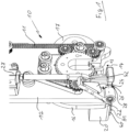
- Figs. 1 to 4 depict a taping head 10 for taping a wire harness W ( Fig. 3 ) wherein the taping head 10 comprises a base plate 12 with a mouth 14 for receiving the wire harness W.
- the mouth 14 has the shape of a broad slit which extends to an outer edge of the base plate 12 with a dead end of the slit having a semi-circular shape.
- a tape dispenser 16 is adapted to rotate a tape roll 17 around a centre C ( Fig. 3 ) of the mouth 14.
- the tape dispenser 16, which also comprises a mouth 15 having the shape of the mouth 14 of the base plate 12, is rotated around the centre C by means of a motor M ( Fig.
- the free end of the tape 17 is unwound from a tape roll which is rotatably supported on the tape dispenser 16 and the tape end is guided by means of a guide roll 34 which is loosely supported on a roll holder 35 mounted on the tape dispenser 16.
- a spring-loaded receptacle comprising two members 30, 32 is provided. Due to the two members 30, 32 the receptacle forms a gap 43 ( Fig. 3 ) for feeding the tape therethrough.
- the members 30 and 32 of the receptacle can be linearly shifted along a respective rod 31 and 33.
- the rods 31 and 33 are arranged in parallel to each other and each member 30, 32 of the receptacle is spring-loaded by means of a spring S1 and S2.
- the members 30, 32 of the receptacle will be pushed against the force of the springs S1 and S2 until the wire harness is located at the centre C of the mouths 14 and 15.
- the members 30 and 32 of the receptacle each comprise an inner wall 36, 38 which is concavely curved such that the shape of the walls corresponds to the outer shape of the wire harness. Furthermore, in the region of the gap 43 both members 30 and 32 comprise a rounded edge for slidingly guiding the tape.
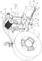
- the free end of the tape can be clamped between an anvil 20 and a clamping element 22 as shown in Figs. 2 and 3 .
- the anvil 20 is a block-like element rigidly mounted to the rotatable tape dispenser 16 and the clamping element 22 comprises a rotatable lever mounted to the base plate 12.
- the rotatable lever can be rotated about an axis A1 which extends in parallel to the extension of the base plate 12 and the clamping element 22 can be rotated about at least 180° from the position shown in Fig. 1 (open position) to the position shown in Figs. 2 , 3 and 4 (closed or clamping position).
- a gear rod 26 ( Fig. 1 ) is provided which can be linearly shifted by means of an actuator 27.
- the linear movement of the gear rod 26 is converted into a rotational movement by means of a gearwheel 28 provided on the clamping element 22 such that the clamping element 22 rotates about the axis A1 if the actuator 27 is actuated to shift the gear rod 26.
- the clamping element 22 comprises a substantially triangular cutting blade 24 and a slit 42 whereas the anvil 20 comprises a slot (not shown) for receiving the cutting blade 24 and a protrusion 40 for clamping the tape.
- the protrusion 40 is received in the slit 42 of the clamping element 22 when the clamping element 22 has received the closed position.
- the tape will be held and clamped between the protrusion 40 and the anvil 20.
- the tape is not cut by the protrusion 40.
- the cutting is achieved by the cutting blade 24 received in the slot of the anvil 20.
- a contact surface of the anvil 20 is located adjacent an inlet of the mouth 15 of the tape dispenser 16 such that the outermost end of the tape is fixed at a location remote from the mouth 15 to avoid interference with the wire harness W.
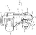
- Fig. 4 shows a perspective view of a further embodiment.
- This embodiment corresponds to the embodiment of Figs. 1 to 3 but comprises two optional support levers 44 and 46 which are rotatable about an axis A2 running in parallel to the axis of the tape roll of the tape 17. Both support levers 44 and 46 can be independently swiveled about the axis A2 by means of a respective actuator.
- Each support lever comprises a support roll 48 ( Fig. 4 ) which can be located at the bottom side of the wire harness W after the wire harness has been placed in the mouths 14 and 15. When the taping head is moved along the length of the wire harness, the wire harness may slide on the support rolls 48.
- the taping head 10 When a taping process is initiated, the taping head 10 is located above the wire harness W and moved towards the wire harness such that the wire harness gets in touch with the walls 36, 38 of the members 30, 32 of the receptacle. If the taping head 10 is moved further downwards the members 30 and 32 are pushed upwards against the forces of the springs S1 and S2 such that the tape gets in contact with the wire harness. After the wire harness W is fully received in the mouths 14 and 15, the actuator 27 is actuated to rotate the clamping element 22 from the closed position shown in Fig. 2 to the open position shown in Fig. 1 . Thereafter, the free end of the tape is released and the tape dispenser 16 can be rotated around the centre C whereby the wire harness W is wrapped with the tape. Simultaneously, the taping head 10 is moved along the length of the wire harness.
- the taping head 10 is moved away from the wire harness W and into a position such that the tape is guided over the support surface of the anvil 20. Thereafter, the clamping element 22 is rotated about the axis A1 by means of the actuator 27 and the tape is cut and simultaneously clamped between the clamping element 21 and the anvil 20.
- the positioning of the taping head 10 can be done by means of a robot in an effective manner. Further, it is possible to move the taping head 10 along the length of the wire harness during the taping process such that a length of the wire harness is wrapped with the tape.
- the taping head described above is very compact and of light weight.
- the taping head can be used with standard taping rolls and the taping process can be done automatically by means of a robot.
- the clamping and the cutting of the tape is done automatically.
Landscapes
- Engineering & Computer Science (AREA)
- Manufacturing & Machinery (AREA)
- Basic Packing Technique (AREA)
- Package Closures (AREA)
- Manufacturing Of Electric Cables (AREA)
Abstract
Description
- The present disclosure relates to taping head for taping a wire harness.
- Taping heads for taping a wire harness with a protective and/or adhesive tape are generally known. Such taping heads are used to manually or automatically wrap a tape around a bundle of wires. In industrial applications there is a need to automatically apply the tape to different wire harnesses or to different sections of a wire harness which requires that a tape which is supplied from a tape roll is cut and repositioned.
- Accordingly, there is a need to provide an improved taping head suitable for an automated wrapping of a tape around a wire harness.
- The present disclosure provides a taping head for taping a wire harness, said taping head comprising a base plate with a mouth for receiving the wire harness and a rotatable tape dispenser with a mouth adapted to rotate a tape roll about a centre of the mouths. A clamping unit is provided for clamping a free end of the tape wherein the clamping unit comprises an anvil rigidly mounted to the rotatable tape dispenser and a clamping element movably mounted to the base plate. By means of the movable clamping element and the anvil it is possible to clamp the free end of the tape between the anvil and the clamping element for positioning the free end at a desired location when initiating the taping process. Since the clamping unit is mounted to the base plate and the tape dispenser, respectively, the taping head can be designed to be very compact and light weight.
- According to an embodiment the clamping element comprises a cutting blade. This provides the advantage that the free end of the tape can be cut and clamped with the clamping unit.
- According to an embodiment the anvil comprises a slot for receiving the cutting blade which improves the cutting and clamping of the free end of the tape.
- According to a further embodiment the clamping element comprises a rotatable lever. The lever may be rotated to abut against the anvil for clamping and optionally also cutting the tape end.
- According to a further embodiment the lever is rotatable about at least 180°. This allows to rotate the lever from one side of the base plate to the opposing side where the tape dispenser is rotatably mounted.
- According to a further embodiment the clamping unit comprises a gear rod and a gear wheel for rotating the clamping element. This also promotes a compact design since the gear rod can be actuated by means of a linear actuator without the necessity of a further electric motor for rotating the clamping element.
- According to a further embodiment the tape dispenser comprises a spring-loaded receptacle for accommodating the wire harness. When positioning the taping head on the wire harness, the wire harness may be received in the receptacle and the taping head can be further fed against the wire harness without significantly deforming the wire harness. This allows a good positioning of the wire harness in the centre of the mouths.
- According to a further embodiment the receptacle forms a gap for the tape. Thereby it is possible to feed the tape through the receptacle such that the tape can be positioned at the outer circumference of the wire harness when initiating the taping process.
- According to a further embodiment a guide roll is located adjacent to the gap in order to feed the tape into the gap on a substantially linear path.
- According to a further embodiment the receptacle has at least one wall that is concavely curved. Such contour corresponds to the outer contour of the wire harness and allows a safe positioning of the taping head above the wire harness.
- According to a further embodiment a contact surface of the anvil is located adjacent an inlet of the mouth of the tape dispenser. Thereby, it is possible to clamp the end of the tape in a position which is laterally shifted from the centre of the mouth such as to avoid any undesired interference between the free end of the tape and the wire harness.
- According to a further embodiment the anvil and the clamping element comprise a slot and a blade for clamping the tape therebetween. The anvil may comprise the slot and the clamping element may comprise the blade or vice versa. Both variants improve the clamping of the tape between the anvil and the clamping element.
- According to a further embodiment at least one rotatable support lever is provided for supporting the wire harness received in the mouths. Since the wire harness which is to be taped is not always fully stretched the support of the wire harness can be improved by a support lever such as to approach a substantially linear formation of the wire harness in the region to be taped.
- According to an embodiment two support levers are provided which can be rotated independently, e.g. by means of an actuator.
- According to a further embodiment the support lever may comprise a support role for reducing friction between the support lever and the wire harness when moving the taping head along the wire harness.
- According to a further embodiment two support levers are provided adjacent to opposing sides of the base plate. Such support levers do not need any additional clamping devices for tensioning the wire harness which reduces weight and improves the compactness of the taping head.
- Exemplary embodiments and functions of the present disclosure are described herein in conjunction with the following drawings, showing schematically:
- Fig. 1
- a perspective view of a taping head;
- Fig. 2
- a perspective view of a detail of the taping head of
Fig. 1 ; - Fig. 3
- a plan view of a detail of the taping head of
Figs. 1 and2 ; and - Fig. 4
- a perspective view of a further embodiment of a taping head.
-
Figs. 1 to 4 depict ataping head 10 for taping a wire harness W (Fig. 3 ) wherein thetaping head 10 comprises abase plate 12 with amouth 14 for receiving the wire harness W. Themouth 14 has the shape of a broad slit which extends to an outer edge of thebase plate 12 with a dead end of the slit having a semi-circular shape. Atape dispenser 16 is adapted to rotate atape roll 17 around a centre C (Fig. 3 ) of themouth 14. Thetape dispenser 16, which also comprises amouth 15 having the shape of themouth 14 of thebase plate 12, is rotated around the centre C by means of a motor M (Fig. 4 ) that rotates a drive pulley and the rotation of the drive pulley is transferred via a toothed belt 11 (Fig. 1 ) to thetape dispenser 16. When thetape dispenser 16 is rotated, thetape roll 17 is also rotated around the centre C. If a wire harness W is placed at the position of the centre C of themouths tape dispenser 16 relative to thebase plate 12. - As shown in
Figs. 2 and3 the free end of thetape 17 is unwound from a tape roll which is rotatably supported on thetape dispenser 16 and the tape end is guided by means of aguide roll 34 which is loosely supported on aroll holder 35 mounted on thetape dispenser 16. - For supporting and accommodating the wire harness W in the
mouths 14 and 15 a spring-loaded receptacle comprising twomembers members Fig. 3 ) for feeding the tape therethrough. Themembers respective rod rods member taping head 10 is positioned over the wire harness W and urged against the wire harness, themembers mouths - The
members inner wall members - In order to clamp and optionally also cut the free end of the tape, the free end of the tape can be clamped between an
anvil 20 and aclamping element 22 as shown inFigs. 2 and3 . Theanvil 20 is a block-like element rigidly mounted to therotatable tape dispenser 16 and the clampingelement 22 comprises a rotatable lever mounted to thebase plate 12. The rotatable lever can be rotated about an axis A1 which extends in parallel to the extension of thebase plate 12 and the clampingelement 22 can be rotated about at least 180° from the position shown inFig. 1 (open position) to the position shown inFigs. 2 ,3 and4 (closed or clamping position). - For rotating the clamping element 22 a gear rod 26 (
Fig. 1 ) is provided which can be linearly shifted by means of anactuator 27. The linear movement of thegear rod 26 is converted into a rotational movement by means of agearwheel 28 provided on the clampingelement 22 such that the clampingelement 22 rotates about the axis A1 if theactuator 27 is actuated to shift thegear rod 26. - As shown in
Fig. 1 , the clampingelement 22 comprises a substantiallytriangular cutting blade 24 and aslit 42 whereas theanvil 20 comprises a slot (not shown) for receiving thecutting blade 24 and aprotrusion 40 for clamping the tape. Theprotrusion 40 is received in theslit 42 of the clampingelement 22 when the clampingelement 22 has received the closed position. The tape will be held and clamped between theprotrusion 40 and theanvil 20. However, the tape is not cut by theprotrusion 40. The cutting is achieved by thecutting blade 24 received in the slot of theanvil 20. - As shown in
Figs. 2 and3 a contact surface of theanvil 20 is located adjacent an inlet of themouth 15 of thetape dispenser 16 such that the outermost end of the tape is fixed at a location remote from themouth 15 to avoid interference with the wire harness W. -
Fig. 4 shows a perspective view of a further embodiment. This embodiment corresponds to the embodiment ofFigs. 1 to 3 but comprises two optional support levers 44 and 46 which are rotatable about an axis A2 running in parallel to the axis of the tape roll of thetape 17. Both support levers 44 and 46 can be independently swiveled about the axis A2 by means of a respective actuator. Each support lever comprises a support roll 48 (Fig. 4 ) which can be located at the bottom side of the wire harness W after the wire harness has been placed in themouths - When a taping process is initiated, the taping
head 10 is located above the wire harness W and moved towards the wire harness such that the wire harness gets in touch with thewalls members head 10 is moved further downwards themembers mouths actuator 27 is actuated to rotate the clampingelement 22 from the closed position shown inFig. 2 to the open position shown inFig. 1 . Thereafter, the free end of the tape is released and thetape dispenser 16 can be rotated around the centre C whereby the wire harness W is wrapped with the tape. Simultaneously, the tapinghead 10 is moved along the length of the wire harness. - After a desired section of the wire harness has been wrapped with tape to a desired extent, the taping
head 10 is moved away from the wire harness W and into a position such that the tape is guided over the support surface of theanvil 20. Thereafter, the clampingelement 22 is rotated about the axis A1 by means of theactuator 27 and the tape is cut and simultaneously clamped between the clamping element 21 and theanvil 20. - Since the
base plate 12 is provided with aquick mount 13 for mounting thebase plate 12 to a robot arm, the positioning of the tapinghead 10 can be done by means of a robot in an effective manner. Further, it is possible to move the tapinghead 10 along the length of the wire harness during the taping process such that a length of the wire harness is wrapped with the tape. - The taping head described above is very compact and of light weight. The taping head can be used with standard taping rolls and the taping process can be done automatically by means of a robot. The clamping and the cutting of the tape is done automatically.
Claims (15)
- Taping head (10) for taping a wire harness (W), said taping head (10) comprising- a base plate (12) with a mouth (14) for receiving the wire harness,- a rotatable tape dispenser (16) with a mouth (15) adapted to rotate a tape roll (17) about a centre (C) of the mouths (14, 15), and- a clamping unit (18) adapted to clamp a free end of the tape, wherein- the clamping unit (18) comprises an anvil (20) rigidly mounted to the rotatable tape dispenser (16) and a clamping element (22) movably mounted to the base plate (12).
- Taping head according to claim 1, wherein the clamping element (22) comprises a cutting blade (24).
- Taping head according to any one of the preceding claims, wherein the anvil (20) comprises a slot for receiving the cutting blade (24).
- Taping head according to any one of the preceding claims, wherein the clamping element (22) comprises a rotatable lever.
- Taping head according to claim 4, wherein the lever is rotatable about at least 180°.
- Taping head according to any one of the preceding claims, wherein the clamping unit (18) comprises a gear rod (26) and a gear wheel (28) for rotating the clamping element (22).
- Taping head according to any one of the preceding claims, wherein the tape dispenser (16) comprises a spring-loaded receptacle (30, 32) for accommodating the wire harness (W).
- Taping head according to claim 7, wherein the receptacle (30, 32) forms a gap (43) for the tape.
- Taping head according to claim 8, further comprising a guide roll (34) located adjacent the gap (43).
- Taping head according to any one of claims 7 to 9, wherein the receptacle (30, 32) has at least one wall (36, 38) that is concavely curved.
- Taping head according to any one of the preceding claims, wherein a contact surface of the anvil (20) is located adjacent an inlet of the mouth (15) of the tape dispenser (16).
- Taping head according to any one of the preceding claims, wherein the anvil (20) and the clamping element (22) comprise a slot and a protrusion (40) for clamping the tape therebetween.
- Taping head according to any one of the preceding claims, further comprising at least one rotatable support lever (44, 46) for supporting the wire harness (W) received in the mouths (14, 15).
- Taping head according to claim 13, wherein the support lever (44, 46) comprises a support roll (48).
- Taping head according to claim 13 or 14, wherein two support levers (46, 48) are provided adjacent two opposing sides of the base plate (12).
Priority Applications (8)
| Application Number | Priority Date | Filing Date | Title |
|---|---|---|---|
| EP21205051.2A EP4174882B1 (en) | 2021-10-27 | 2021-10-27 | Taping head |
| PL21205051.2T PL4174882T3 (en) | 2021-10-27 | 2021-10-27 | Taping head |
| MA63085A MA63085B1 (en) | 2021-10-27 | 2021-10-27 | Taping head |
| RS20251207A RS67459B1 (en) | 2021-10-27 | 2021-10-27 | Taping head |
| PT212050512T PT4174882T (en) | 2021-10-27 | 2021-10-27 | Taping head |
| EP22203260.9A EP4174883B1 (en) | 2021-10-27 | 2022-10-24 | Taping head |
| US17/973,709 US12112863B2 (en) | 2021-10-27 | 2022-10-26 | Taping head |
| CN202211323216.2A CN116022465B (en) | 2021-10-27 | 2022-10-27 | Binding head |
Applications Claiming Priority (1)
| Application Number | Priority Date | Filing Date | Title |
|---|---|---|---|
| EP21205051.2A EP4174882B1 (en) | 2021-10-27 | 2021-10-27 | Taping head |
Publications (2)
| Publication Number | Publication Date |
|---|---|
| EP4174882A1 true EP4174882A1 (en) | 2023-05-03 |
| EP4174882B1 EP4174882B1 (en) | 2025-09-24 |
Family
ID=78621675
Family Applications (2)
| Application Number | Title | Priority Date | Filing Date |
|---|---|---|---|
| EP21205051.2A Active EP4174882B1 (en) | 2021-10-27 | 2021-10-27 | Taping head |
| EP22203260.9A Active EP4174883B1 (en) | 2021-10-27 | 2022-10-24 | Taping head |
Family Applications After (1)
| Application Number | Title | Priority Date | Filing Date |
|---|---|---|---|
| EP22203260.9A Active EP4174883B1 (en) | 2021-10-27 | 2022-10-24 | Taping head |
Country Status (7)
| Country | Link |
|---|---|
| US (1) | US12112863B2 (en) |
| EP (2) | EP4174882B1 (en) |
| CN (1) | CN116022465B (en) |
| MA (1) | MA63085B1 (en) |
| PL (1) | PL4174882T3 (en) |
| PT (1) | PT4174882T (en) |
| RS (1) | RS67459B1 (en) |
Families Citing this family (3)
| Publication number | Priority date | Publication date | Assignee | Title |
|---|---|---|---|---|
| EP4713949A1 (en) * | 2023-05-17 | 2026-03-25 | LEONI Bordnetz-Systeme GmbH | Assembly head for automatically wrapping a wiring harness, a changing system and a method for automatically changing a banding unit in the assembly head |
| CN119898509B (en) * | 2025-02-12 | 2025-11-07 | 重庆海德世拉索系统(集团)有限公司 | Manual device for identifying wire harness with winding and binding function |
| CN121281935B (en) * | 2025-12-10 | 2026-03-06 | 浙江普川电子有限公司 | High-precision controllable stroke tape wrapping machine |
Citations (6)
| Publication number | Priority date | Publication date | Assignee | Title |
|---|---|---|---|---|
| WO2003013958A1 (en) * | 2001-07-26 | 2003-02-20 | Spirula Aktiebolag | Taping machine for wire harness |
| KR100802502B1 (en) * | 2007-02-09 | 2008-02-13 | 신재학 | Portable wire taping device |
| US20110017392A1 (en) * | 2009-03-03 | 2011-01-27 | Dania Nevarez Erives | Mechatronic gun for taping a harness |
| DE202015001990U1 (en) * | 2015-03-17 | 2015-04-17 | Kabatec GmbH & Co. KG | Device for wrapping an elongate bundle material with an adhesive tape |
| DE202017102503U1 (en) * | 2017-04-27 | 2017-05-17 | Lisa Dräxlmaier GmbH | Device for wrapping a cable harness with a belt |
| CN108455356A (en) * | 2018-01-18 | 2018-08-28 | 伯朝平 | Portable adhesive tape auto-winding device |
Family Cites Families (10)
| Publication number | Priority date | Publication date | Assignee | Title |
|---|---|---|---|---|
| JPS60163202U (en) * | 1984-03-17 | 1985-10-30 | 住友電気工業株式会社 | tying machine |
| JP3324485B2 (en) | 1998-01-23 | 2002-09-17 | 住友電装株式会社 | Taping device |
| GB9907736D0 (en) * | 1999-04-01 | 1999-05-26 | Rue De Int Ltd | Banding apparatus and method |
| DE102013205509B4 (en) | 2013-03-27 | 2019-02-28 | S-Y Systems Technologies Europe Gmbh | Device for wrapping a cable harness |
| US9786416B1 (en) | 2016-03-28 | 2017-10-10 | Te Connectivity Corporation | Tape dispensing tool |
| DE202016002622U1 (en) * | 2016-04-22 | 2016-05-30 | Kabatec GmbH & Co. KG | Device for wrapping an elongate bundle material with an adhesive tape |
| KR102003192B1 (en) | 2016-11-15 | 2019-10-04 | 경림기전 주식회사 | Taping apparatus for wiring harness |
| KR101976553B1 (en) | 2017-03-27 | 2019-05-09 | (주)미래테크원 | taping device for wire harness |
| DE102017130895B4 (en) | 2017-12-21 | 2023-06-29 | Lisa Dräxlmaier GmbH | Winding device and method for fully automated wrapping of a bundle of wires with an adhesive tape |
| CN110444344B (en) * | 2019-08-28 | 2024-05-31 | 诸暨中澳自动化设备有限公司 | Thin full-automatic adhesive tape winding machine head, equipment and method thereof |
-
2021
- 2021-10-27 EP EP21205051.2A patent/EP4174882B1/en active Active
- 2021-10-27 RS RS20251207A patent/RS67459B1/en unknown
- 2021-10-27 PT PT212050512T patent/PT4174882T/en unknown
- 2021-10-27 PL PL21205051.2T patent/PL4174882T3/en unknown
- 2021-10-27 MA MA63085A patent/MA63085B1/en unknown
-
2022
- 2022-10-24 EP EP22203260.9A patent/EP4174883B1/en active Active
- 2022-10-26 US US17/973,709 patent/US12112863B2/en active Active
- 2022-10-27 CN CN202211323216.2A patent/CN116022465B/en active Active
Patent Citations (6)
| Publication number | Priority date | Publication date | Assignee | Title |
|---|---|---|---|---|
| WO2003013958A1 (en) * | 2001-07-26 | 2003-02-20 | Spirula Aktiebolag | Taping machine for wire harness |
| KR100802502B1 (en) * | 2007-02-09 | 2008-02-13 | 신재학 | Portable wire taping device |
| US20110017392A1 (en) * | 2009-03-03 | 2011-01-27 | Dania Nevarez Erives | Mechatronic gun for taping a harness |
| DE202015001990U1 (en) * | 2015-03-17 | 2015-04-17 | Kabatec GmbH & Co. KG | Device for wrapping an elongate bundle material with an adhesive tape |
| DE202017102503U1 (en) * | 2017-04-27 | 2017-05-17 | Lisa Dräxlmaier GmbH | Device for wrapping a cable harness with a belt |
| CN108455356A (en) * | 2018-01-18 | 2018-08-28 | 伯朝平 | Portable adhesive tape auto-winding device |
Also Published As
| Publication number | Publication date |
|---|---|
| EP4174883B1 (en) | 2025-09-24 |
| EP4174882B1 (en) | 2025-09-24 |
| EP4174883A3 (en) | 2023-08-16 |
| PL4174882T3 (en) | 2026-02-23 |
| MA63085B1 (en) | 2025-10-31 |
| PT4174882T (en) | 2025-10-27 |
| US12112863B2 (en) | 2024-10-08 |
| CN116022465A (en) | 2023-04-28 |
| EP4174883A2 (en) | 2023-05-03 |
| US20230129360A1 (en) | 2023-04-27 |
| CN116022465B (en) | 2026-05-01 |
| RS67459B1 (en) | 2025-12-31 |
Similar Documents
| Publication | Publication Date | Title |
|---|---|---|
| EP4174883A2 (en) | Taping head | |
| CN109950003A (en) | Winding device and method for fully automatically winding a wire bundle with an adhesive tape | |
| EP2884507B1 (en) | Winding device and method for binding wire material to terminal | |
| EP0050910B1 (en) | Wire end processing apparatus | |
| US7325764B2 (en) | Method and apparatus for winding field coils for dynamo-electric machines | |
| JP3324485B2 (en) | Taping device | |
| US20080271510A1 (en) | Wire processing machine and method for manufacturing and processing a cut length of wire | |
| JP7347906B2 (en) | Installation head and method for automatic wrapping of wire harnesses | |
| CN105800380A (en) | Wire packing machine | |
| WO1989005047A1 (en) | Electrical cable-making apparatus | |
| CN111822924B (en) | Automatic production equipment for wiring harness | |
| CN111822925B (en) | Wire harness and automatic production method thereof | |
| US5954918A (en) | Tape wrapping machine | |
| JPS59132756A (en) | Coil winding method and coil winder | |
| CN120153438A (en) | Assembly head and method for automatically winding cable strands | |
| JP3703503B2 (en) | Cable bundling device for cable processing machine | |
| EP4362049A1 (en) | Taping head | |
| JPH07211427A (en) | Electric wire straightener in electric wire processor | |
| US20090039194A1 (en) | Coiler and method for manufacturing a coil | |
| CN111790858B (en) | A change material mechanism for pencil | |
| CN114834967B (en) | Automatic knotting wire winding machine | |
| CN117696780A (en) | Automatic integrated wire cutting machine for thin lead wires | |
| US4571803A (en) | Fabrication apparatus for cushioned line support | |
| JPH0927222A (en) | Wire guide unit, and constant length wire cutting device | |
| US7419116B2 (en) | Method and apparatus for winding field coils for dynamo-electric machines |
Legal Events
| Date | Code | Title | Description |
|---|---|---|---|
| PUAI | Public reference made under article 153(3) epc to a published international application that has entered the european phase |
Free format text: ORIGINAL CODE: 0009012 |
|
| STAA | Information on the status of an ep patent application or granted ep patent |
Free format text: STATUS: THE APPLICATION HAS BEEN PUBLISHED |
|
| AK | Designated contracting states |
Kind code of ref document: A1 Designated state(s): AL AT BE BG CH CY CZ DE DK EE ES FI FR GB GR HR HU IE IS IT LI LT LU LV MC MK MT NL NO PL PT RO RS SE SI SK SM TR |
|
| STAA | Information on the status of an ep patent application or granted ep patent |
Free format text: STATUS: REQUEST FOR EXAMINATION WAS MADE |
|
| 17P | Request for examination filed |
Effective date: 20231030 |
|
| RAV | Requested validation state of the european patent: fee paid |
Extension state: TN Effective date: 20231030 Extension state: MA Effective date: 20231030 |
|
| RBV | Designated contracting states (corrected) |
Designated state(s): AL AT BE BG CH CY CZ DE DK EE ES FI FR GB GR HR HU IE IS IT LI LT LU LV MC MK MT NL NO PL PT RO RS SE SI SK SM TR |
|
| RAP1 | Party data changed (applicant data changed or rights of an application transferred) |
Owner name: APTIV TECHNOLOGIES AG |
|
| RAP3 | Party data changed (applicant data changed or rights of an application transferred) |
Owner name: APTIV TECHNOLOGIES AG |
|
| GRAP | Despatch of communication of intention to grant a patent |
Free format text: ORIGINAL CODE: EPIDOSNIGR1 |
|
| STAA | Information on the status of an ep patent application or granted ep patent |
Free format text: STATUS: GRANT OF PATENT IS INTENDED |
|
| INTG | Intention to grant announced |
Effective date: 20250416 |
|
| GRAS | Grant fee paid |
Free format text: ORIGINAL CODE: EPIDOSNIGR3 |
|
| GRAA | (expected) grant |
Free format text: ORIGINAL CODE: 0009210 |
|
| STAA | Information on the status of an ep patent application or granted ep patent |
Free format text: STATUS: THE PATENT HAS BEEN GRANTED |
|
| P01 | Opt-out of the competence of the unified patent court (upc) registered |
Free format text: CASE NUMBER: UPC_APP_2794_4174882/2025 Effective date: 20250807 |
|
| AK | Designated contracting states |
Kind code of ref document: B1 Designated state(s): AL AT BE BG CH CY CZ DE DK EE ES FI FR GB GR HR HU IE IS IT LI LT LU LV MC MK MT NL NO PL PT RO RS SE SI SK SM TR |
|
| REG | Reference to a national code |
Ref country code: GB Ref legal event code: FG4D Ref country code: TN Ref legal event code: VAGR Ref document number: TN/P/2025/0376 Country of ref document: TN |
|
| REG | Reference to a national code |
Ref country code: CH Ref legal event code: EP |
|
| REG | Reference to a national code |
Ref country code: DE Ref legal event code: R096 Ref document number: 602021039058 Country of ref document: DE |
|
| REG | Reference to a national code |
Ref country code: IE Ref legal event code: FG4D |
|
| REG | Reference to a national code |
Ref country code: PT Ref legal event code: SC4A Ref document number: 4174882 Country of ref document: PT Date of ref document: 20251027 Kind code of ref document: T Free format text: AVAILABILITY OF NATIONAL TRANSLATION Effective date: 20251021 |
|
| REG | Reference to a national code |
Ref country code: MA Ref legal event code: VAGR Ref document number: 63085 Country of ref document: MA Kind code of ref document: B1 |
|
| VSFP | Annual fee paid to validation state [announced via postgrant information from national office to epo] |
Ref country code: MA Payment date: 20251024 Year of fee payment: 5 |
|
| PGFP | Annual fee paid to national office [announced via postgrant information from national office to epo] |
Ref country code: PT Payment date: 20251024 Year of fee payment: 5 |
|
| PGFP | Annual fee paid to national office [announced via postgrant information from national office to epo] |
Ref country code: DE Payment date: 20250917 Year of fee payment: 5 |
|
| PGFP | Annual fee paid to national office [announced via postgrant information from national office to epo] |
Ref country code: GB Payment date: 20251015 Year of fee payment: 5 |
|
| PG25 | Lapsed in a contracting state [announced via postgrant information from national office to epo] |
Ref country code: NO Free format text: LAPSE BECAUSE OF FAILURE TO SUBMIT A TRANSLATION OF THE DESCRIPTION OR TO PAY THE FEE WITHIN THE PRESCRIBED TIME-LIMIT Effective date: 20251224 |
|
| REG | Reference to a national code |
Ref country code: LT Ref legal event code: MG9D |
|
| PGFP | Annual fee paid to national office [announced via postgrant information from national office to epo] |
Ref country code: AT Payment date: 20260113 Year of fee payment: 5 |
|
| PG25 | Lapsed in a contracting state [announced via postgrant information from national office to epo] |
Ref country code: FI Free format text: LAPSE BECAUSE OF FAILURE TO SUBMIT A TRANSLATION OF THE DESCRIPTION OR TO PAY THE FEE WITHIN THE PRESCRIBED TIME-LIMIT Effective date: 20250924 |
|
| PG25 | Lapsed in a contracting state [announced via postgrant information from national office to epo] |
Ref country code: HR Free format text: LAPSE BECAUSE OF FAILURE TO SUBMIT A TRANSLATION OF THE DESCRIPTION OR TO PAY THE FEE WITHIN THE PRESCRIBED TIME-LIMIT Effective date: 20250924 |
|
| PGFP | Annual fee paid to national office [announced via postgrant information from national office to epo] |
Ref country code: FR Payment date: 20251126 Year of fee payment: 6 |
|
| PG25 | Lapsed in a contracting state [announced via postgrant information from national office to epo] |
Ref country code: GR Free format text: LAPSE BECAUSE OF FAILURE TO SUBMIT A TRANSLATION OF THE DESCRIPTION OR TO PAY THE FEE WITHIN THE PRESCRIBED TIME-LIMIT Effective date: 20251225 |
|
| PGFP | Annual fee paid to national office [announced via postgrant information from national office to epo] |
Ref country code: TR Payment date: 20251020 Year of fee payment: 5 |
|
| PG25 | Lapsed in a contracting state [announced via postgrant information from national office to epo] |
Ref country code: SE Free format text: LAPSE BECAUSE OF FAILURE TO SUBMIT A TRANSLATION OF THE DESCRIPTION OR TO PAY THE FEE WITHIN THE PRESCRIBED TIME-LIMIT Effective date: 20250924 |
|
| PG25 | Lapsed in a contracting state [announced via postgrant information from national office to epo] |
Ref country code: LV Free format text: LAPSE BECAUSE OF FAILURE TO SUBMIT A TRANSLATION OF THE DESCRIPTION OR TO PAY THE FEE WITHIN THE PRESCRIBED TIME-LIMIT Effective date: 20250924 |
|
| PG25 | Lapsed in a contracting state [announced via postgrant information from national office to epo] |
Ref country code: BG Free format text: LAPSE BECAUSE OF FAILURE TO SUBMIT A TRANSLATION OF THE DESCRIPTION OR TO PAY THE FEE WITHIN THE PRESCRIBED TIME-LIMIT Effective date: 20250924 |
|
| PGFP | Annual fee paid to national office [announced via postgrant information from national office to epo] |
Ref country code: RO Payment date: 20251216 Year of fee payment: 5 |
|
| PGFP | Annual fee paid to national office [announced via postgrant information from national office to epo] |
Ref country code: RS Payment date: 20251024 Year of fee payment: 5 |
|
| REG | Reference to a national code |
Ref country code: NL Ref legal event code: MP Effective date: 20250924 |
|
| PG25 | Lapsed in a contracting state [announced via postgrant information from national office to epo] |
Ref country code: NL Free format text: LAPSE BECAUSE OF FAILURE TO SUBMIT A TRANSLATION OF THE DESCRIPTION OR TO PAY THE FEE WITHIN THE PRESCRIBED TIME-LIMIT Effective date: 20250924 |
|
| REG | Reference to a national code |
Ref country code: AT Ref legal event code: MK05 Ref document number: 1841077 Country of ref document: AT Kind code of ref document: T Effective date: 20250924 |
|
| PG25 | Lapsed in a contracting state [announced via postgrant information from national office to epo] |
Ref country code: SM Free format text: LAPSE BECAUSE OF FAILURE TO SUBMIT A TRANSLATION OF THE DESCRIPTION OR TO PAY THE FEE WITHIN THE PRESCRIBED TIME-LIMIT Effective date: 20250924 |
|
| PG25 | Lapsed in a contracting state [announced via postgrant information from national office to epo] |
Ref country code: ES Free format text: LAPSE BECAUSE OF FAILURE TO SUBMIT A TRANSLATION OF THE DESCRIPTION OR TO PAY THE FEE WITHIN THE PRESCRIBED TIME-LIMIT Effective date: 20250924 |
|
| PG25 | Lapsed in a contracting state [announced via postgrant information from national office to epo] |
Ref country code: AT Free format text: LAPSE BECAUSE OF FAILURE TO SUBMIT A TRANSLATION OF THE DESCRIPTION OR TO PAY THE FEE WITHIN THE PRESCRIBED TIME-LIMIT Effective date: 20250924 |
|
| PG25 | Lapsed in a contracting state [announced via postgrant information from national office to epo] |
Ref country code: IT Free format text: LAPSE BECAUSE OF FAILURE TO SUBMIT A TRANSLATION OF THE DESCRIPTION OR TO PAY THE FEE WITHIN THE PRESCRIBED TIME-LIMIT Effective date: 20250924 |
|
| PG25 | Lapsed in a contracting state [announced via postgrant information from national office to epo] |
Ref country code: IS Free format text: LAPSE BECAUSE OF FAILURE TO SUBMIT A TRANSLATION OF THE DESCRIPTION OR TO PAY THE FEE WITHIN THE PRESCRIBED TIME-LIMIT Effective date: 20260124 |
|
| PG25 | Lapsed in a contracting state [announced via postgrant information from national office to epo] |
Ref country code: CZ Free format text: LAPSE BECAUSE OF FAILURE TO SUBMIT A TRANSLATION OF THE DESCRIPTION OR TO PAY THE FEE WITHIN THE PRESCRIBED TIME-LIMIT Effective date: 20250924 |
|
| PGFP | Annual fee paid to national office [announced via postgrant information from national office to epo] |
Ref country code: PL Payment date: 20260204 Year of fee payment: 6 |
|
| PG25 | Lapsed in a contracting state [announced via postgrant information from national office to epo] |
Ref country code: SK Free format text: LAPSE BECAUSE OF FAILURE TO SUBMIT A TRANSLATION OF THE DESCRIPTION OR TO PAY THE FEE WITHIN THE PRESCRIBED TIME-LIMIT Effective date: 20250924 Ref country code: EE Free format text: LAPSE BECAUSE OF FAILURE TO SUBMIT A TRANSLATION OF THE DESCRIPTION OR TO PAY THE FEE WITHIN THE PRESCRIBED TIME-LIMIT Effective date: 20250924 |