EP4174533A1 - Stablinsenanordnung, optisches gerät, bildsensor, drucker, inspektionsvorrichtung, mutterglaszusammensetzung für stablinse mit brechungsindexverteilung und herstellungsverfahren - Google Patents
Stablinsenanordnung, optisches gerät, bildsensor, drucker, inspektionsvorrichtung, mutterglaszusammensetzung für stablinse mit brechungsindexverteilung und herstellungsverfahren Download PDFInfo
- Publication number
- EP4174533A1 EP4174533A1 EP21829495.7A EP21829495A EP4174533A1 EP 4174533 A1 EP4174533 A1 EP 4174533A1 EP 21829495 A EP21829495 A EP 21829495A EP 4174533 A1 EP4174533 A1 EP 4174533A1
- Authority
- EP
- European Patent Office
- Prior art keywords
- rod lens
- gradient
- index
- lens array
- mol
- Prior art date
- Legal status (The legal status is an assumption and is not a legal conclusion. Google has not performed a legal analysis and makes no representation as to the accuracy of the status listed.)
- Pending
Links
Images





Classifications
-
- G—PHYSICS
- G02—OPTICS
- G02B—OPTICAL ELEMENTS, SYSTEMS OR APPARATUS
- G02B3/00—Simple or compound lenses
- G02B3/0006—Arrays
- G02B3/0037—Arrays characterized by the distribution or form of lenses
-
- C—CHEMISTRY; METALLURGY
- C03—GLASS; MINERAL OR SLAG WOOL
- C03C—CHEMICAL COMPOSITION OF GLASSES, GLAZES OR VITREOUS ENAMELS; SURFACE TREATMENT OF GLASS; SURFACE TREATMENT OF FIBRES OR FILAMENTS MADE FROM GLASS, MINERALS OR SLAGS; JOINING GLASS TO GLASS OR OTHER MATERIALS
- C03C3/00—Glass compositions
- C03C3/04—Glass compositions containing silica
- C03C3/076—Glass compositions containing silica with 40% to 90% silica, by weight
- C03C3/089—Glass compositions containing silica with 40% to 90% silica, by weight containing boron
-
- C—CHEMISTRY; METALLURGY
- C03—GLASS; MINERAL OR SLAG WOOL
- C03C—CHEMICAL COMPOSITION OF GLASSES, GLAZES OR VITREOUS ENAMELS; SURFACE TREATMENT OF GLASS; SURFACE TREATMENT OF FIBRES OR FILAMENTS MADE FROM GLASS, MINERALS OR SLAGS; JOINING GLASS TO GLASS OR OTHER MATERIALS
- C03C21/00—Treatment of glass, not in the form of fibres or filaments, by diffusing ions or metals in the surface
- C03C21/001—Treatment of glass, not in the form of fibres or filaments, by diffusing ions or metals in the surface in liquid phase, e.g. molten salts, solutions
- C03C21/002—Treatment of glass, not in the form of fibres or filaments, by diffusing ions or metals in the surface in liquid phase, e.g. molten salts, solutions to perform ion-exchange between alkali ions
-
- C—CHEMISTRY; METALLURGY
- C03—GLASS; MINERAL OR SLAG WOOL
- C03C—CHEMICAL COMPOSITION OF GLASSES, GLAZES OR VITREOUS ENAMELS; SURFACE TREATMENT OF GLASS; SURFACE TREATMENT OF FIBRES OR FILAMENTS MADE FROM GLASS, MINERALS OR SLAGS; JOINING GLASS TO GLASS OR OTHER MATERIALS
- C03C3/00—Glass compositions
- C03C3/04—Glass compositions containing silica
- C03C3/076—Glass compositions containing silica with 40% to 90% silica, by weight
- C03C3/078—Glass compositions containing silica with 40% to 90% silica, by weight containing an oxide of a divalent metal, e.g. an oxide of zinc
-
- G—PHYSICS
- G02—OPTICS
- G02B—OPTICAL ELEMENTS, SYSTEMS OR APPARATUS
- G02B13/00—Optical objectives specially designed for the purposes specified below
- G02B13/24—Optical objectives specially designed for the purposes specified below for reproducing or copying at short object distances
- G02B13/26—Optical objectives specially designed for the purposes specified below for reproducing or copying at short object distances for reproducing with unit magnification
-
- G—PHYSICS
- G02—OPTICS
- G02B—OPTICAL ELEMENTS, SYSTEMS OR APPARATUS
- G02B3/00—Simple or compound lenses
- G02B3/0087—Simple or compound lenses with index gradient
-
- G—PHYSICS
- G02—OPTICS
- G02B—OPTICAL ELEMENTS, SYSTEMS OR APPARATUS
- G02B3/00—Simple or compound lenses
- G02B3/02—Simple or compound lenses with non-spherical faces
- G02B3/06—Simple or compound lenses with non-spherical faces with cylindrical or toric faces
-
- G—PHYSICS
- G03—PHOTOGRAPHY; CINEMATOGRAPHY; ANALOGOUS TECHNIQUES USING WAVES OTHER THAN OPTICAL WAVES; ELECTROGRAPHY; HOLOGRAPHY
- G03G—ELECTROGRAPHY; ELECTROPHOTOGRAPHY; MAGNETOGRAPHY
- G03G15/00—Apparatus for electrographic processes using a charge pattern
- G03G15/04—Apparatus for electrographic processes using a charge pattern for exposing, i.e. imagewise exposure by optically projecting the original image on a photoconductive recording material
- G03G15/0409—Details of projection optics
-
- G—PHYSICS
- G06—COMPUTING OR CALCULATING; COUNTING
- G06T—IMAGE DATA PROCESSING OR GENERATION, IN GENERAL
- G06T7/00—Image analysis
- G06T7/0002—Inspection of images, e.g. flaw detection
- G06T7/0004—Industrial image inspection
-
- H—ELECTRICITY
- H04—ELECTRIC COMMUNICATION TECHNIQUE
- H04N—PICTORIAL COMMUNICATION, e.g. TELEVISION
- H04N1/00—Scanning, transmission or reproduction of documents or the like, e.g. facsimile transmission; Details thereof
- H04N1/024—Details of scanning heads ; Means for illuminating the original
- H04N1/028—Details of scanning heads ; Means for illuminating the original for picture information pick-up
- H04N1/02815—Means for illuminating the original, not specific to a particular type of pick-up head
- H04N1/02845—Means for illuminating the original, not specific to a particular type of pick-up head using an elongated light source, e.g. tubular lamp, LED array
-
- H—ELECTRICITY
- H04—ELECTRIC COMMUNICATION TECHNIQUE
- H04N—PICTORIAL COMMUNICATION, e.g. TELEVISION
- H04N1/00—Scanning, transmission or reproduction of documents or the like, e.g. facsimile transmission; Details thereof
- H04N1/024—Details of scanning heads ; Means for illuminating the original
- H04N1/028—Details of scanning heads ; Means for illuminating the original for picture information pick-up
- H04N1/03—Details of scanning heads ; Means for illuminating the original for picture information pick-up with photodetectors arranged in a substantially linear array
- H04N1/031—Details of scanning heads ; Means for illuminating the original for picture information pick-up with photodetectors arranged in a substantially linear array the photodetectors having a one-to-one and optically positive correspondence with the scanned picture elements, e.g. linear contact sensors
- H04N1/0313—Direct contact pick-up heads, i.e. heads having no array of elements to project the scanned image elements onto the photodectors
-
- H—ELECTRICITY
- H04—ELECTRIC COMMUNICATION TECHNIQUE
- H04N—PICTORIAL COMMUNICATION, e.g. TELEVISION
- H04N23/00—Cameras or camera modules comprising electronic image sensors; Control thereof
- H04N23/56—Cameras or camera modules comprising electronic image sensors; Control thereof provided with illuminating means
-
- H—ELECTRICITY
- H04—ELECTRIC COMMUNICATION TECHNIQUE
- H04N—PICTORIAL COMMUNICATION, e.g. TELEVISION
- H04N25/00—Circuitry of solid-state image sensors [SSIS]; Control thereof
- H04N25/70—SSIS architectures; Circuits associated therewith
- H04N25/701—Line sensors
-
- G—PHYSICS
- G02—OPTICS
- G02B—OPTICAL ELEMENTS, SYSTEMS OR APPARATUS
- G02B3/00—Simple or compound lenses
- G02B2003/0093—Simple or compound lenses characterised by the shape
Definitions
- the present invention relates to a rod lens array, an optical device, an image sensor, a printer, an inspection apparatus, a base glass composition for a gradient-index rod lens, and a method of manufacturing a gradient-index rod lens.
- Patent Literature 1 describes a surface defect inspecting apparatus including a light source, an irradiation unit, a light collecting unit, and an observation unit.
- the observation unit consists of an imaging lens and an imaging device, such as a CCD image sensor or a CMOS image sensor.
- Patent Literature 2 describes an inspection apparatus suitable for appearance inspection of photosensitive drums of electrophotographic copiers and printers.
- This inspection apparatus includes a camera device that photographs a photosensitive drum by a plurality of one-dimensional CCD cameras arrayed in one row.
- a CIS includes a rod lens array.
- gradient-index rod lenses are used in general.
- Patent Literatures 3 to 5 each describe a gradient-index rod lens and a rod lens array in which a plurality of gradient-index rod lenses are arrayed.
- a gradient-index rod lens is a rod-like (bar-like) lens that has a refractive-index distribution in which the refractive index continuously decreases from the center toward the outer periphery.
- a difference ⁇ n in refractive index between the peripheral surface and the central axis of the lens is 0.003 or more.
- the aperture angle (2 ⁇ ) is included in the range below about 10°, which suggests that this is not desirable.
- Patent Literature 3 is considered to suggest that an aperture angle ( ⁇ ) of less than 5° is not desirable.
- a gradient-index rod lens according to an example has an aperture angle of about 10.1 to 12.9°.
- a gradient-index rod lens according to an example has an aperture angle of 10.1 to 12.0°.
- Patent Literatures 1 and 2 fail to describe the use of a gradient-index rod lens.
- the gradient-index rod lenses described in Patent Literatures 3 to 5 each have a large aperture angle. This is far from advantageous from the viewpoint of achieving a large depth of field in the gradient-index rod lens, and the gradient-index rod lenses described in Patent Literatures 3 to 5 are each considered to have a small depth of field.
- the present invention provides a rod lens array having a large depth of field. Further, the present invention provides an optical device, an image sensor, a printer, and an inspection apparatus, each of which includes such a rod lens array. In addition, the present invention provides a base glass composition for a gradient-index rod lens that is advantageous for increasing the depth of field of a rod lens array. Moreover, the present invention provides an advantageous method for manufacturing a gradient-index rod lens having a large depth of field.
- the present invention provides a rod lens array forming an erecting equal-magnification image, the rod lens array comprising:
- the present invention provides an optical device including the above rod lens array.
- the present invention provides an image sensor including:
- the present invention provides a printer including a write head having the above rod lens array.
- the present invention provides an inspection apparatus including:
- the present invention provides a base glass composition for a gradient-index rod lens including, in mol%:
- the present invention provides a method of manufacturing a gradient-index rod lens including:
- the above rod lens array has a large depth of field. Further, the above base glass composition for a gradient-index rod lens is advantageous for increasing the depth of field of the rod lens array.
- Image data to be collected in appearance inspection of an inspection object needs to have a resolution at which a defect of the inspection object can be identified.
- a camera including a one-dimensional CCD sensor is used to obtain image data with a high resolution
- the effective width in which image capturing can be performed by one camera is small. Accordingly, it is sometimes difficult to capture an image of the entire inspection object by one camera. For example, when a pixel size corresponding to the resolution required in image data is 90 ⁇ m, a width of a region in which image capturing can be performed by a camera including a one-dimensional CCD sensor of 4096 pixels is about 370 mm.
- the CIS includes a plurality of one-dimensional photodetectors disposed on a substrate and a rod lens array.
- the rod lens array forms an erecting equal-magnification image.
- the rod lens array is, for example, an array of a plurality of gradient-index rod lenses.
- the gradient-index rod lens is a substantially cylindrical lens having a refractive-index distribution in its radial direction, where the refractive index varies from the central portion toward the peripheral portion in the radial direction of the gradient-index rod lens.
- CISs including a rod lens array
- the distance between the imaging device and the object to be photographed can be reduced to about one-tenth of that in conventional camera systems including a CCD sensor and a lens, and such CISs are advantageous in device miniaturization.
- the depth of field (DOF) which is a characteristic value indicating an acceptable range of the distance between the object to be photographed and the lens, is small. This causes a problem that the inspection object has a portion in focus and a portion out of focus when the inspection object varies in thickness. Consequently, an image of the portion out of focus is not clear, which leads a possibility of overlooking of a defect and misidentification of a defect.
- the gradient-index rod lenses described in Patent Literatures 3 to 5 each have a large aperture angle, and this is far from advantageous from the viewpoint of increasing the DOF of the gradient-index rod lens.
- the present inventors have drastically reviewed the conditions of the glass composition used for manufacturing the gradient-index rod lens.
- the present inventors have finally found a gradient-index rod lens capable of achieving the DOF in a desired range.
- the gradient-index rod lens according to the present invention can be utilized not only in the technical field of appearance inspection of the inspection object but also throughout the technical field of image formation by image scanners, copiers, facsimiles, printers, and the like.
- a gradient-index rod lens 1b has an aperture angle ⁇ of 3 to 6°.
- the radius of the gradient-index rod lens 1b is represented by r 0 .
- the refractive index at the center of the gradient-index rod lens 1b is represented by n 0 .
- a refractive-index distribution constant of the gradient-index rod lens 1b is represented by ⁇ A.
- the aperture angle ⁇ is represented by sin -1 (n 0 • ⁇ A•r 0 ).
- an imaging distance (TC) the distance from an objective to an erecting image is 45 to 75 mm.
- the gradient-index rod lens 1b has a depth of field (DOF) of 1.5 to 3.0 mm.
- DOF depth of field
- the DOF of the gradient-index rod lens 1b is determined by subtracting the minimum value of the working distance from the maximum value of the working distance.
- the value of the modulation transfer function (MTF) at a spatial frequency of 6 Ip/mm is 30% or more.
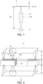
- the DOF of the gradient-index rod lens 1b can be determined by, for example, arranging a rod lens array 10a, a line pattern 3, and a photodetector 2 at a predetermined interval in the optical axis direction and obtaining the value of the MTF while varying the distance between the rod lens array 10a and the line pattern 3.
- the rod lens array 10a is configured by arraying a plurality of gradient-index rod lenses 1b in a direction perpendicular to the optical axis.
- the line pattern 3 has black and white line pairs corresponding to a spatial frequency of 6 Ip/mm.
- the photodetector 2 is, for example, a CCD sensor.
- the line pattern 3 is irradiated with the light.
- the color filter may transmit, for example, light having a wavelength in the range of 500 to 600 nm, or may transmit mainly light having a wavelength of 530 nm.
- the value of the MTF can be determined as the reproduction ratio of an image (output image) obtained by imaging on the photodetector 2 by the rod lens array 10a with respect to an image (input image) of the line pattern 3 having a predetermined spatial frequency composed of bright portions and dark portions before entering the rod lens array 10a.
- a distance D max between the line pattern 3 and the photodetector 2 for which the value of the MTF is maximum is determined.
- D max an erecting equal-magnification image is obtained by the rod lens array 10a.
- the line pattern 3 is moved in the positive direction ( ⁇ L > 0) and the negative direction ( ⁇ L ⁇ 0) of the Z-axis parallel to the optical axis to obtain the values of the MTF at the respective positions.
- a predetermined acceptable range for the value of the MTF is set, so that the maximum value and the minimum value of the working distance can be obtained.
- the DOF of the gradient-index rod lens 1b can be determined.
- ⁇ L > 0 the distance between the line pattern 3 and the rod lens array 10a is larger than the working distance corresponding to the distance D max .
- ⁇ L ⁇ 0 the distance between the line pattern 3 and the rod lens array 10a is smaller than the working distance corresponding to the distance D max .
- the gradient-index rod lens 1b and the rod lens array 10a have DOFs within the above range, and are accordingly advantageous for, for example, acquiring image data suitable for appearance inspection of an inspection object having a non-uniform thickness, a step, and unevenness. Accordingly, the gradient-index rod lens 1b and the rod lens array 10a can contribute to enhancement in accuracy of appearance inspection of the inspection object and to sophistication of the inspection standard.
- the DOF of the gradient-index rod lens 1b is desirably 1.5 mm or more, more desirably 1.8 mm or more, and still more desirably 2 mm or more.
- the DOF of the gradient-index rod lens 1b is desirably 2.8 mm or less, and more desirably 2.5 mm or less.
- the gradient-index rod lens 1b When forming an erecting equal-magnification image, the gradient-index rod lens 1b has the maximum value of the MTF at a lens-imaging position distance L i that is not limited to any specific value.
- the lens-imaging position distance L i is, for example, 13 to 28 mm.
- the gradient-index rod lens 1b has a desired DOF and is advantageous from the viewpoint of inspecting an object having a step within a predetermined range.
- the lens-imaging position distance L i is desirably 15 mm or more, and more desirably 18 mm or more.
- the lens-imaging position distance L i is desirably 25 mm or less, and more desirably 22 mm or less.
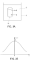
- the aperture angle ⁇ of the gradient-index rod lens 1b is defined, for example, as shown in FIG. 2 .
- the aperture angle ⁇ is the maximum value of an angle formed by a beam capable of entering one end of the optical axis of the gradient-index rod lens 1b and the optical axis.
- the sign F1 represents a subject plane (object plane)
- the sign F2 represents a light receiving plane (image plane) in a photodetector or the like.
- the sign Z 0 represents the length of the gradient-index rod lens 1b.
- the sign L o represents the distance between the subject plane F1 and the gradient-index rod lens 1b for which the value of the MTF is maximum.
- the sign L i represents the distance between the image plane F2 and the gradient-index rod lens 1b for which the value of the MTF is maximum.
- the rod lens array 10a constitutes an imaging system of substantial erecting equal-magnification images, and the distance L i is substantially equal to the distance L o .
- the sign X 0 represents the radius of the field of view of the gradient-index rod lens 1b.
- the aperture angle ⁇ of the gradient-index rod lens 1b can be determined, for example, according to a method described in the examples.
- the aperture angle ⁇ may be determined by using the refractive index n 0 at the center of the gradient-index rod lens 1b instead of the refractive index Nc of a glass rod before ion exchange.
- the refractive index Nc or n 0 can be determined by the V-block method described in Japanese Industrial Standards (JIS) B 7071-2: 2018.
- the aperture angle ⁇ of the gradient-index rod lens 1b may be 3.5° or more or 3.7° or more.
- the aperture angle ⁇ of the gradient-index rod lens 1b is desirably 5.5° or less, and more desirably 5.2° or less.
- the maximum value of the MTF of the rod lens array 10a is not limited to any specific value, and is, for example, 60% or more, desirably 65% or more, and more desirably 70% or more.
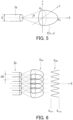
- the gradient-index rod lens 1b has, for example, a refractive-index distribution in the radial direction as shown in FIG. 3B .
- the refractive index n 0 at the origin in FIG. 3B means the refractive index on the central axis of the gradient-index rod lens 1b.
- the sign r represents the position of the gradient-index rod lens 1b in the radial direction.
- Equation (1) The refractive-index distribution of the gradient-index rod lens 1b is represented by, for example, Equation (1) below.
- Equation (1) r represents the distance from the optical axis of the gradient-index rod lens 1b
- n(r) represents the refractive index of the gradient-index rod lens 1b at the distance r
- n 0 represents the refractive index at the center of the gradient-index rod lens 1b
- ⁇ A, h 4 , h 6 , and h 8 each represent a refractive-index distribution coefficient.
- n r 2 n 0 2 • 1 ⁇ ⁇ A • r 2 + h 4 • ⁇ A • r 4 + h 6 • ⁇ A • r 6 + h 8 • ⁇ A • r 8
- Equation (2) the refractive-index distribution of the gradient-index rod lens 1b can be approximated by Equation (2).
- n r n 0 • 1 ⁇ A / 2 • r 2
- the refractive index n 0 at the center of the gradient-index rod lens 1b is not limited to any specific value, and is, for example, 1.51 to 1.65. This easily increases the DOF, and formation of the refractive-index distribution by ion exchange of base glass is not so difficult.
- the refractive index n 0 at the center of the gradient-index rod lens 1b is desirably 1.54 to 1.62.
- the refractive-index distribution constant ( ⁇ A) of the gradient-index rod lens 1b is not limited to any specific value.
- the sign ⁇ A means the square root of A.
- the refractive-index distribution constant ⁇ A of the gradient-index rod lens 1b is, for example, 0.130 to 0.230 mm -1 .
- the aperture angle ⁇ of the gradient-index rod lens 1b is easily included in a desired range.
- the DOF of the gradient-index rod lens 1b is easily adjusted to a desired range.
- the refractive-index distribution constant ⁇ A of the gradient-index rod lens 1b may be 0.140 mm -1 or more, 0.150 mm -1 or more, or 0.170 mm -1 or more.
- the refractive-index distribution constant of the gradient-index rod lens 1b is desirably 0.210 mm -1 or less, and more desirably 0.205 mm -1 or less.
- the imaging distance (TC) of an erecting image in the gradient-index rod lens 1b is 45 to 75 mm from the viewpoint of adjusting the DOF of the gradient-index rod lens 1b to a desired range.
- the imaging distance (TC) of the erecting image formed by the gradient-index rod lens 1b should be larger than a predetermined value from the viewpoint of adjusting the aperture angle and the DOF to desired ranges while taking into consideration the balance with a lens length Z 0 .
- the imaging distance (TC) of the erecting image in the gradient-index rod lens 1b may be 47 mm or more, 50 mm or more, 53 mm or more, or 54 mm or more.
- the imaging distance of the erecting image formed by the gradient-index rod lens 1b may be 70 mm or less or 67 mm or less from the viewpoint of avoiding an increase in size of an optical device into which the gradient-index rod lens 1b is incorporated.
- the gradient-index rod lens 1b when used in a contact image sensor including an LED or the like as the illumination light, the gradient-index rod lens 1b has a size suitable for reproducing uniform illumination having little unevenness while suppressing an excessive decrease in its intensity.
- the gradient-index rod lens 1b may have, as necessary, a structure for preventing generation of noise light (so-called white noise (stray light)) caused by reflection, from the side surface of the lens, of incident light having an incident angle larger than an aperture angle.
- a structure can be, for example, a light absorbing layer or a light scattering layer, provided on the side surface of the lens.
- the gradient-index rod lens 1b may have a core-cladding structure in which a colored layer serving as the light absorbing layer is disposed on the side surface of the lens.
- the lens diameter of the outer shape can be different from the lens effective diameter substantially contributing to image formation.
- the gradient-index rod lens 1b may have, on the side surface near the outermost peripheral surface thereof, a structure in which a fine asperity portion serving as the light scattering layer is formed.
- the gradient-index rod lens 1b may be made of a glass lens.
- the glass composition at the center of the gradient-index rod lens 1b satisfies, for example, the following requirements, in mol%: 40% ⁇ SiO 2 ⁇ 65%; 0% ⁇ TiO 2 ⁇ 10%; 0.1% ⁇ MgO ⁇ 22%; 0.15% ⁇ ZnO ⁇ 15%; 0.5% ⁇ Li 2 O ⁇ 4%; 2% ⁇ Na 2 O ⁇ 20%; 0% ⁇ B 2 O 3 ⁇ 20%; 0% ⁇ Al 2 O 3 ⁇ 10%; and 0% ⁇ K 2 O ⁇ 3%.
- the base glass composition for a gradient-index rod lens includes, for example, in mol%: 40% ⁇ SiO 2 ⁇ 65%; 0% ⁇ TiO 2 ⁇ 10%; 0.1% ⁇ MgO ⁇ 22%; 0.15% ⁇ ZnO ⁇ 15%; 0.5% ⁇ Li 2 O ⁇ 4%; 2% ⁇ Na 2 O ⁇ 20%; 0% ⁇ B 2 O 3 ⁇ 20%; 0% ⁇ Al 2 O 3 ⁇ 10%; 0% ⁇ K 2 O ⁇ 3%; 0% ⁇ Cs 2 O ⁇ 3%; 0% ⁇ Y 2 O 3 ⁇ 5%; 0% ⁇ ZrO 2 ⁇ 2%; 0% ⁇ Nb 2 O 5 ⁇ 5%; 0% ⁇ In 2 O 3 ⁇ 5%; 0% ⁇ La 2 O 3 ⁇ 5%; and 0% ⁇ Ta 2 O 5 ⁇ 5%.
- this base glass composition includes at least two selected from the group consisting of CaO, SrO, and BaO each in a range of 0.1 mol% or more and 15 mol% or less. Further, this base glass composition satisfies the following requirements, in mol%: 2% ⁇ MgO + ZnO; 0.07 ⁇ ZnO/(MgO + ZnO) ⁇ 0.93; 2.5% ⁇ Li 2 O + Na 2 O ⁇ 24%; and 0% ⁇ Y 2 O 3 + ZrO 2 + Nb 2 O 5 + In 2 O 3 + La 2 O 3 + Ta 2 O 5 ⁇ 11%.
- a base glass composition it is possible to achieve a gradient-index rod lens having a desired DOF.
- the gradient-index rod lens 1b can be manufactured, for example, by performing an ion exchange process on a glass rod consisting of the above glass composition.
- SiO 2 is an essential component that forms the network structure of glass.
- the SiO 2 content of less than 40 mol% relatively increases the contents of other components necessary to allow the optical properties as a gradient-index rod lens to develop after ion exchange. In this case, thus, devitrification tends to occur. Further, this content of less than 40 mol% markedly deteriorates the chemical durability as a glass composition. On the other hand, this content exceeding 65 mol% limits the contents of other components, for example, an alkali component for forming a refractive-index distribution, a component for increasing a refractive index, and a component for adjusting the physical property value. This makes it difficult to obtain a practical glass composition. Accordingly, the SiO 2 content is 40 mol% or more and 65 mol% or less.
- TiO 2 is an essential component that acts to increase the refractive index of the glass composition.
- By increasing the refractive index of the base glass composition it is possible to increase the refractive index at the center of a gradient-index rod lens obtained from the glass composition.
- Further, by increasing the TiO 2 content it is possible to bring the refractive-index distribution of the gradient-index rod lens into a more ideal condition, thereby manufacturing a gradient-index rod lens having an excellent resolution.
- the TiO 2 content is 10 mol%, no deterioration in image resolution based on the resulting lens is observed, whereas when this content is less than 1 mol%, the image resolution noticeably deteriorates and consequently a practical lens cannot be obtained.
- the TiO 2 content is 1 mol% or more and 10 mol% or less.
- the TiO 2 content is desirably 2 mol% or more and 8 mol% or less.
- MgO is an essential component that acts to lower the melting temperature of the glass composition to increase the refractive index difference ( ⁇ n) between the central portion and the peripheral portion of the lens after ion exchange.
- ⁇ n refractive index difference
- the MgO content exceeds 22 mol%, devitrification tends to occur. Further, when the MgO content exceeds 22 mol%, the contents of other components excessively decrease, and consequently a practical glass composition cannot be obtained. Accordingly, the MgO content is 0.1 mol% or more and 22 mol% or less. From the viewpoint of achieving a sufficient refractive index difference, the MgO content is desirably 2 mol% or more.
- the MgO content is 2 mol% or more
- the contents of alkaline-earth metal oxides can be controlled more appropriately for the purpose of further reducing the mobility of alkali ions. That is, the MgO content is desirably 2 mol% or more and 22 mol% or less, and more desirably 2 mol% or more and 16 mol% or less.
- ZnO acts to enhance the weather resistance of the glass composition and the gradient-index rod lens.
- ZnO may be added for partial substitution for MgO.
- the ZnO content is 0.15 mol% or more and 15 mol% or less.
- the contents of MgO and ZnO are adjusted such that the sum of the contents of MgO and ZnO (MgO + ZnO) is 2 mol% or more.
- the contents of MgO and ZnO are adjusted such that the ratio of the ZnO content to the sum of the contents of MgO and ZnO (ZnO/(MgO + ZnO)) is 0.07 ⁇ ZnO/(MgO + ZnO) ⁇ 0.93.
- the ZnO content is desirably 3 mol% or more and 15 mol% or less.
- MgO + ZnO may be 6 mol% or more, and a requirement 0.12 ⁇ ZnO/(MgO + ZnO) ⁇ 0.93 can be satisfied.
- the ZnO content is desirably 8 mol% or less. From the viewpoint of even further increasing the weather resistance of the glass composition and the gradient-index rod lens, the ZnO content is more desirably 4 mol% or more and 15 mol% or less.
- MgO + ZnO may be 6 mol% or more, and MgO + ZnO can be 6 mol% or more and 22 mol% or less. MgO + ZnO may be 15 mol% or less.
- ZnO/(MgO + ZnO) is desirably 0.07 or more and 0.9 or less, more desirably 0.25 or more and 0.85 or less, still more desirably 0.25 or more and 0.8 or less, and particularly desirably 0.3 or more and 0.8 or less.
- Li 2 O is an essential component, and is one of the most important components for obtaining a gradient-index rod lens through ion exchange of the glass composition of the present invention. It has been conventionally considered that a low Li 2 O content in the glass composition does not allow a sufficient concentration distribution, that is, a sufficient refractive-index distribution, to develop through ion exchange and consequently a suitable gradient-index rod lens cannot be achieved. However, the present inventors have newly found that, even with a glass composition having a Li 2 O content of 4 mol% or less, a gradient-index rod lens having a suitable refractive-index distribution and a large DOF can be produced by performing ion exchange under predetermined conditions.
- the Li 2 O content is 0.5 mol% or more, desirably 0.7 mol% or more, and more desirably 1 mol% or more. Further, the Li 2 O content is 4 mol% or less, desirably 3.5 mol% or less, more desirably 3 mol% or less, and still more desirably 2 mol% or less.
- One of the features of the gradient-index rod lens 1b lies in having a lower Li 2 O content than various prior arts. There have been conventionally manufacturing process-related reasons for impossibility in reduction of the Li 2 O content. The present inventors have newly found that, by performing new improvements such as limitation of the throughput of glass rods per batch in the ion exchange method and reduction of the initial content of Li in the molten salt, a gradient-index rod lens can be obtained in which an aperture angle smaller than before and a practical resolution are achieved while a lens aberration such as a field curvature is suppressed.
- Na 2 O promotes ion exchange between Li and an ion of ion exchange species to be substituted for a Li ion (ion contained in a molten salt) and maintains an adequate ion mobility.
- ion exchange rate By maintaining an adequate ion mobility, it is possible to adjust the ion exchange rate properly, thereby adjusting the optical properties of the gradient-index rod lens.
- the Na 2 O content in the glass composition is less than 2 mol%, the glass hardens while being molded, which makes the molding difficult.
- the melting temperature of the glass is raised markedly, which makes lens production difficult. Further, it is difficult to sufficiently achieve the effect of maintaining an adequate ion mobility.
- the Na 2 O content exceeds 20%, the chemical durability of the glass deteriorates, resulting in a lack of practicality. Accordingly, the Na 2 O content is 2 mol% or more, desirably 5 mol% or more, and more desirably 10 mol% or more. Further, the Na 2 O content is 20 mol% or less, and desirably 17 mol% or less.
- Li 2 O + Na 2 O the sum of the Li 2 O content and the Na 2 O content (Li 2 O + Na 2 O) in the glass composition is 2.5 mol% or more and less than 24 mol%. Owing to Li 2 O + Na 2 O within this range, an image having a favorable resolution can be obtained by a gradient-index rod lens manufactured using this glass composition.
- Li 2 O + Na 2 O is desirably 6 mol% or more, and more desirably 10 mol% or more.
- Li 2 O/Na 2 O is, for example, 0.2 or less, desirably 0.15 or less, and more desirably 0.1 or less.
- the above glass composition may further include the following components.
- B 2 O 3 is an optional component that forms the network structure of glass, and acts to promote vitrification of the glass composition and adjust the viscosity thereof while hardly changing the resolving power and the aperture angle ⁇ of the resulting gradient-index rod lens.
- B 2 O 3 also acts to lower the ion exchange rate of the glass composition, though the extent of which is small.
- B 2 O 3 may be added in a case, for example, where although the respective contents of the essential components described above are included in the ranges specified in the present invention, the content of a portion of the components becomes relatively large as a composition and the glass stability is deteriorated (e.g., devitrification tends to occur).
- the B 2 O 3 content that can be added without changing the resolving power and the aperture angle of the resulting gradient-index rod lens is, for example, 20 mol% or less. Accordingly, the B 2 O 3 content is 0 mol% or more and 20 mol% or less. This content is desirably 0 mol% or more and 10 mol% or less. In the case where the glass composition contains B 2 O 3 , its content is desirably 1 mol% or more and 10 mol% or less.
- the base glass composition for a gradient-index rod lens may contain, as an optional component, Al 2 O 3 whose content is 0 mol% or more and 10 mol% or less.
- the sum of the contents of SiO 2 , TiO 2 , and B 2 O 3 (SiO 2 + TiO 2 + B 2 O 3 ) in the base glass composition for a gradient-index rod lens is, for example, 41 mol% or more and 70 mol% or less, and desirably 50 mol% or more and 70 mol% or less.
- the base glass composition for a gradient-index rod lens may contain at least one component selected from the group consisting of Y 2 O 3 , ZrO 2 , Nb 2 O 5 , In 2 O 3 , La 2 O 3 , and Ta 2 O 5 for the purpose of adjusting the refractive index or enhancing the weather resistance of a gradient-index rod lens resulting from ion exchange.
- the sum of the contents of these components is 0 mol% or more and 11 mol% or less.
- the base glass composition for a gradient-index rod lens contains these components, the sum of the contents of these components is desirably 0.2 mol% or more and 6 mol% or less. Further, the sum of the contents of these components and the ZnO content is desirably 15 mol% or less.
- the Y 2 O 3 content is desirably 0 mol% or more and 5 mol% or less.
- the ZrO 2 content is desirably 0 mol% or more and 2 mol% or less.
- its content is 0.2 mol% or more and 2 mol% or less.
- Nb 2 O 5 , In 2 O 3 , La 2 O 3 , and Ta 2 O 5 are each desirably 0 mol% or more and 5 mol% or less.
- K 2 O and Cs 2 O are optional components that act to reduce the mobility of alkali ions by the mixed alkali effect.
- the respective contents of K 2 O and Cs 2 O are each, for example, 0 mol% or more and 3 mol% or less.
- the Cs 2 O content is desirably less than 2 mol%, more desirably 0 mol% or more and 1 mol% or less, and still more desirably 0.5 mol% or less.
- the base glass composition for a gradient-index rod lens should be substantially free of Cs 2 O.
- substantially free means that the content of the component referred to is less than 0.1 mol%.
- the base glass composition for a gradient-index rod lens may contain GeO 2 as an additional component.
- the GeO 2 content can be 0 mol% or more and 10 mol% or less.
- the base glass composition for a gradient-index rod lens may contain, as an additive, at least one selected from the group consisting of SnO 2 , As 2 O 3 , and Sb 2 O 3 .
- the respective contents of SnO 2 , As 2 O 3 , and Sb 2 O 3 each can be 0 mol% or more and 1 mol% or less.
- the base glass composition for a gradient-index rod lens may consist substantially of the above components.
- the respective contents of the components contained in the glass composition and the relation among the respective contents of the components (the sum and the content ratio) satisfy the above requirements.
- the phrase "consist substantially of” as used herein means to allow for the content of impurities of less than 0.1 mol%.
- the base glass composition for a gradient-index rod lens is substantially free of lead (PbO as a typical compound). Further, the gradient-index rod lens 1b is also substantially free of lead.
- the base glass composition for a gradient-index rod lens has, for example, a water resistance of Class 1 determined in accordance with Japan Optical Glass Industrial Standards (JOGIS) 06-2009.
- the base glass composition for a gradient-index rod lens has a high water resistance
- a gradient-index rod lens manufactured using the base glass composition for a gradient-index rod lens also tends to have a high water resistance.
- Glass forming the gradient-index rod lens may also have a water resistance of Class 1 determined in accordance with JOGIS 06-2009.
- the base glass composition for a gradient-index rod lens contains an oxide of a first alkali metal element.
- the gradient-index rod lens 1b can be manufactured, for example, by a method including the following steps (I) and (II):
- the glass rod 1a is charged into the molten salt S inside a container V such that the glass rod 1a is immersed in the molten salt S for a predetermined time.
- the molten salt S for example, at least one of potassium nitrate and sodium nitrate is melted.
- Immersing the glass rod 1a in the molten salt S for example, causes dissolution of cations of the first alkali metal element Q such as Li (lithium) contained in the glass rod 1a into the molten salt S.
- cations of the second alkali metal element R such as K (potassium) contained in the molten salt S enter the glass rod 1a.
- the temperature of the molten salt S and the immersion time of the glass rod 1a in the molten salt S it is possible to appropriately control the ion exchange between the cations of the first alkali metal element Q and the cations of the second alkali metal element R.
- a concentration distribution of specific monovalent cations is generated, and a refractive-index distribution as shown in FIG. 3B is formed in the glass rod 1a according to the concentration distribution.
- the gradient-index rod lens 1b can be manufactured from the glass rod 1a.
- the gradient-index rod lens 1b typically has the highest refractive index in the central portion.
- the refractive index n 0 in the central portion of the gradient-index rod lens 1b may be equal to the refractive index Nc of the base glass composition for a gradient-index rod lens before an ion exchange process.
- cations such as alkali metal elements do not substantially migrate in the glass rod 1a, and accordingly the composition of the glass in the central portion of the gradient-index rod lens can be the same as the composition of the base glass before the ion exchange.
- An optical product according to the present invention is not limited to any specific product as long as the optical product includes the gradient-index rod lens 1b.
- the gradient-index rod lens 1b can be used to provide, for example, a predetermined rod lens array.
- the rod lens array forms an erecting equal-magnification image.
- the rod lens array in this case can have, as the array of the gradient-index rod lenses 1b, a zero-dimensional array, a one-dimensional array, or a two-dimensional array.
- the zero-dimensional array is, for example, a configuration in which a single gradient-index rod lens 1b is disposed, and is expected to exert a desired action by an optical product including a single gradient-index rod lens 1b.
- the one-dimensional array is a configuration in which the plurality of gradient-index rod lenses 1b are arrayed in one row in a specific direction.
- the specific direction is referred to as a main-scanning direction, and a direction that is perpendicular to the main-scanning direction and perpendicular to the optical axis is referred to as a sub-scanning direction.
- the plurality of gradient-index rod lenses 1b are arrayed to have optical axes substantially parallel to each other.
- the two-dimensional array is a configuration in which the lenses are arrayed in a one-dimensional array and further arrayed in a direction different from that of the one-dimensional array.
- the two-dimensional array can be, for example, a configuration in which the plurality of gradient-index rod lenses 1b are arrayed in two or more rows along the main-scanning direction.
- a rod lens array 10b it is possible to obtain a wide-range erecting equal-magnification image by using the gradient-index rod lenses each having even a small diameter.
- the imaging distance (TC) in the gradient-index rod lens 1b is 45 to 75 mm.
- the rod lens array has an imaging distance of 45 to 75 mm.
- the gradient-index rod lens 1b has a depth of field (DOF) of 1.5 to 3.0 mm. In other words, the depth of field (DOF) in the rod lens array is 1.5 to 3.0 mm.
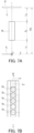
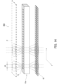
- the gradient-index rod lens 1b can be used to provide, for example, the rod lens array 10b shown in FIG. 4 .
- the plurality of gradient-index rod lenses 1b are arrayed to have optical axes substantially parallel to each other.
- the plurality of gradient-index rod lenses 1b are arrayed in two rows to form a two-dimensional array.
- the plurality of gradient-index rod lenses 1b are arrayed, for example, between a pair of fiber-reinforced plastic (FRP) substrates 5.
- FRP fiber-reinforced plastic
- the space between the plurality of gradient-index rod lenses 1b and the space between the FRP substrate 5 and the gradient-index rod lenses 1b are filled with black resin 7.
- the plurality of gradient-index rod lenses 1b are made into one unit.
- the rod lens array 10b having such a configuration can be produced, for example, as described below.
- the plurality of gradient-index rod lenses 1b are arrayed substantially parallel to each other on the surface of one FRP substrate 5, and the lenses are sandwiched by the other FRP substrate 5.
- the space between the pair of FRP substrates 5 is filled with the black resin 7 to make all the portions into one unit. Further, the end surfaces of the gradient-index rod lenses 1b are polished as necessary.
- an erecting equal-magnification image is formed in a range of the radius of the field of view X 0 by one gradient-index rod lens 1b.
- the quantity of light is highest on the optical axis of the gradient-index rod lens 1b and decreases with distance from the optical axis. Accordingly, the quantity of light varies in the field of view represented by the radius of the field of view X 0 . Since the rod lens array is formed by arraying such gradient-index rod lenses 1b, an unevenness of quantity of light occurs depending on the array pitch of the gradient-index rod lenses 1b.
- the brightness of the image can fluctuate periodically in the main-scanning direction (the array direction of the rod lenses) depending on the array pitch of the rod lenses in the rod lens array. This may cause the optical device to be unable to exhibit a desired performance.
- FIG. 5 schematically shows the relation between the field of view of the erecting equal-magnification and the light quantity distribution in the gradient-index rod lens 1b having a diameter D.
- a light quantity distribution E(x, y) in the field of view of the erecting equal-magnification is represented by the following Equation (3).
- E 0 represents the light quantity at the center of the field of view of the erecting equal-magnification image.
- E x , y E 0 • ⁇ 1 ⁇ x 2 + y 2 / X 0 2
- FIG. 6 schematically shows light quantity distributions E M1 and E M2 in a rod lens array in which the gradient-index rod lenses 1b having the above light quantity distribution E(x, y) are arrayed in an array shape.
- the light quantity distribution E M1 represents the light quantity distributions of the gradient-index rod lenses 1b individually
- the light quantity distribution E M2 represents a composition of the light quantity distributions of the gradient-index rod lenses 1b.
- the light quantity distribution in the rod lens array exhibits a periodic unevenness of quantity of light along the main-scanning direction (x direction) depending on the array pitch of the gradient-index rod lenses 1b.
- An unevenness of quantity of light ⁇ E (0, 0) along the reference line is represented by, for example, the following Equation (4).
- E max and E min respectively represent the maximum value and the minimum value in the light quantity distribution along the reference line.
- the unevenness of quantity of light ⁇ E (0,0) can be determined by actually producing the rod lens array and measuring the light quantity distribution. Further, in the case where the optical constant of the gradient-index rod lens 1b is known, ⁇ E (0, 0) can be calculated on the basis of Equations (3) and (4).
- the rod lens array has, for example, a lens group in which the plurality of gradient-index rod lenses 1b are arrayed in a row along the main-scanning direction.
- the reference line is a line of an intersection between an image plane of an erecting equal-magnification image and specifical plane.
- the specifical plane is a plane equidistant in the sub scanning direction (y direction) from one virtual end line and the other virtual end line of the lens group (rod lens array) in an end surface of the gradient-index rod lens 1b viewed along a direction parallel to the central axis of the gradient-index rod lens 1b.
- FIGS. 7A and 7B conceptually show a reference line L R of a rod lens array having a lens group in which the plurality of gradient-index rod lenses 1b are arrayed in one row.
- FIGS. 8A and 8B conceptually show the reference line L R of a rod lens array having a lens group in which the plurality of gradient-index rod lenses 1b are arrayed in two rows.
- FIGS. 9A and 9B conceptually show the reference line L R of a rod lens array having a lens group in which the plurality of gradient-index rod lenses 1b are arrayed in three rows.
- the sign P represents an object such as a document or an object to be inspected
- the sign f 1 represents a plane that can be a reading plane or an inspection plane for the object.
- the sign f 2 represents an image plane.
- the unevenness of quantity of light ⁇ E (0, 0) along the reference line is not limited to any specific value.
- the unevenness of quantity of light ⁇ E (0, 0) along the reference line is, for example, 6% or less. This facilitates formation of an erecting equal-magnification image with a desired quantity of light in an optical device using the rod lens array.
- a predetermined domain is a domain for which the light quantity distribution has substantial periodicity in the main-scanning direction (x direction), where the unevenness of quantity of light ⁇ E (0, 0) along the reference line may be obtained, for example, within the predetermined domain.
- the predetermined range in the x direction may be determined so as to include the position.
- the unevenness of quantity of light ⁇ E (0, 0) along the reference line is desirably 5% or less, and more desirably 4% or less.
- the unevenness of quantity of light ⁇ E (0, 0) along the reference line is, for example, 1% or more. Accordingly, it is easy to avoid adjustment of the aperture angle that would cause a decrease in DOF in the gradient-index rod lens 1b.
- the rod lens array 10b can be modified from various viewpoints, and materials known in producing the rod lens array may be used as materials of each of the components of the rod lens array. Further, the array of the plurality of gradient-index rod lenses 1b is not limited to two rows. The plurality of gradient-index rod lenses 1b may be arrayed in one row, two rows, or three or more rows. By arraying the gradient-index rod lenses 1b in a large number of rows, it is possible to provide a rod lens array suitable for a large area.
- the gradient-index rod lens 1b can be a plastic rod lens having the above optical performance.
- the plastic rod lens can be produced by, for example, a copolymerization method, a sol-gel method, or an inter-diffusion method.
- resins whose refractive index gradually decreases from the center toward the outer periphery are laminated concentrically, and then counter diffusion of materials between the layers is performed such that the refractive index varies continuously. After such a treatment, the resins are further heated to be stretched. Thus, a bar-like rod lens is obtained.
- the plastic rod lens is easy to handle and generally inexpensive owing to its material properties, and has advantages in some cases.
- the rod lens array including the gradient-index rod lens 1b has a large DOF, and is excellent in weather resistance in some cases, and can be widely used in optical devices such as scanners, copiers, facsimiles, printers, CISs, and line cameras. In other words, it is possible to provide an optical device including the rod lens array. Further, owing to being excellent particularly in water resistance (moisture resistance), the rod lens array including the gradient-index rod lens 1b is applicable to the above optical devices and the like not only in general air conditioning for offices and the like but also in various environments including factories exposed to high temperature and high humidity conditions and logistics, such as storage warehouses and transport trucks.
- the optical device including the rod lens array further includes, for example, a linear light source and an optical sensor.
- the rod lens array 10b can be used to provide, for example, a contact image sensor (CIS) 100 shown in FIG. 10 .
- the CIS 100 includes, for example, the rod lens array 10b, a housing 11, a linear optical sensor 12, a linear illuminator 13, and a document platen 14.
- the linear optical sensor 12 extends in the main-scanning direction of the rod lens array 10b.
- a direction parallel to the X-axis is the main-scanning direction
- a direction parallel to the Y-axis is the sub-scanning direction.
- the linear illuminator 13 extends in the main-scanning direction of the rod lens array 10b.
- the document platen 14 is formed of a glass sheet.
- the glass sheet forming the document platen 14 is disposed so as to cover the opening of the housing 11.
- the rod lens array 10b, the linear optical sensor 12, and the linear illuminator 13 are disposed inside the housing 11.
- the linear illuminator 13 linearly illuminates a document P placed on the document platen 14 with illumination light.
- the rod lens array 10b is disposed such that light reflected from the surface of the document P enters the linear optical sensor 12.
- the linear optical sensor 12 is disposed such that the light reflected from the document is collected through the rod lens array 10b.
- the image sensor 100 may be configured to be capable of imaging an object other than a document.
- the rod lens array 10b includes the gradient-index rod lens 1b having a large DOF, a read image with a favorable quality is easily achieved even with respect to, for example, a partially floating portion of the document P caused by a wrinkle, a spread portion, or the like.
- the rod lens array 10b can be used to provide, for example, an image sensor 300 shown in FIG. 11 .
- the image sensor 300 includes a housing 31, a linear optical sensor 32, a linear illuminator 33, a first spacer 34a, a second spacer 34b, and a substrate 35.
- the linear illuminator 33 is disposed outside the housing 31.
- the rod lens array 10b is positioned relative to and fixed to the housing 31 by the first spacer 34a and the second spacer 34b.
- the image sensor 300 may be applied to an apparatus for inspecting the appearance of an inspection object, and may be used to obtain an image from the inspection object (object to be inspected) instead of the document P.
- the inspection object is irradiated with a beam emitted from the linear illuminator 33, and light reflected from the surface of the inspection object is imaged on the linear optical sensor 32 by the imaging action of the rod lens array 10b.
- the linear optical sensor 32 can sequentially convert one-dimensional image information of the surface of the inspection object into electric signals for output.
- the rod lens array 10b can be used to provide, for example, a printer 500 shown in FIG. 12 .
- the printer 500 includes a write head 51, a photosensitive drum 52, a charger 53, a developer 54, a transfer device 55, a fixing device 56, an erase lamp 57, a cleaner 58, and a sheet feeding cassette 59.
- the rod lens array 10b is disposed inside the write head 51.
- the printer 500 is an electrophotographic printer.
- the write head 51 includes the rod lens array 10b and a light emitting element array (not shown).
- the rod lens array 10b constitutes an imaging optical system for exposure of light emitted from the light emitting element array onto the photosensitive drum 52.
- the rod lens array 10b has a focal point located on the surface of the photosensitive drum 52 to constitute an erecting equal-magnification optical system.
- the charger 53 uniformly charges the surface of the photosensitive drum 52 that is rotating.
- the write head 51 irradiates the photosensitive layer of the photosensitive drum 52 with light of a dot image corresponding to an image to be formed. This neutralizes the charge in the light irradiation region of the photosensitive layer, and thus a latent image is formed on the photosensitive layer.
- toner is carried onto the photosensitive layer by the developer 54.
- the toner adheres to the portion of the photosensitive layer where the latent image has been formed.
- the transfer device 55 transfers the adhering toner onto a sheet fed from the cassette.
- the fixing device 56 heats the sheet to fix the toner onto the sheet.
- an image is formed.
- the erase lamp 57 neutralizes the charge across the entire region of the photosensitive drum 52.
- the cleaner 58 removes the toner remaining on the photosensitive layer.
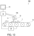
- the rod lens array 10b can be used to provide, for example, an inspection apparatus 700 shown in FIG. 13 .
- the inspection apparatus 700 includes an image sensor 71, a linear illuminator 72 as the light source, a controller 73, an output device 74, a conveyor 75, and a conveyance control device 76. Inside the image sensor 71, the rod lens array 10b is disposed.
- the conveyor 75 is, for example, a belt conveyor.
- the conveyor 75 conveys an inspection object T, such as a printed-circuit board, a textile, or a sheet.
- the conveyance control device 76 is a digital computer for controlling the conveyor 75, and outputs a control signal for adjusting the conveying speed of the conveyor 75 to the conveyor 75.
- the image sensor 71 and the linear illuminator 72 are, for example, disposed above the conveyor 75, and the conveyor 75 causes the inspection object T to pass just under the image sensor 71.
- the image sensor 71 and the linear illuminator 72 are disposed such that clear image data of the inspection object T is obtained.
- the controller 73 is a digital computer for forming image data of the inspection object T. When the inspection object T passes just under the image sensor 71, the controller 73 continuously acquires one-dimensional image information from the image sensor 71. In addition, the controller 73 acquires conveyance position information of the inspection object T from the conveyance control device 76.
- the controller 73 performs calculation processing on the basis of the one-dimensional image information acquired from the image sensor 71 and the conveyance position information acquired from the conveyance control device 76 to form two-dimensional image information.
- the two-dimensional image information thus formed is compared with information featuring a defect, such as foreign matters, cracks, and pinholes, stored beforehand in the controller 73.
- the controller 73 thus specifies the presence or absence of a defect, the number of defects, and the position of the defect in the inspection object T.
- the controller 73 may determine whether the inspection object T is defective on the basis of the comparison results.
- the output device 74 is, for example, a monitor, and displays the two-dimensional image information formed by the controller 73.
- the above optical devices may be configured to be capable of acquiring a color image of an object, such as an object to be inspected, a subject, and a document.
- an optical device 900 employing color filters can be provided.
- the optical device 900 includes the rod lens array 10a, a white light source (not shown), and an optical sensor 92.
- the white light source emits light of different wavelengths, such as R, G, and B.
- the white light source is, for example, a linear light source.
- the optical sensor 92 is disposed along the main-scanning direction of the rod lens array 10a and has a plurality of segments with different dominant wavelengths.
- the optical sensor 92 is, for example, a sensor such as photodiode including respective color filters corresponding to R (red), G (green), and B (blue).
- the plurality of segments each include, for example, respective color filters corresponding to R, G, and B arrayed in the sub-scanning direction (y direction). As shown in FIG. 14 , the plurality of segments of the optical sensor 92 are arrayed in the main-scanning direction (x direction). Pixel information pieces corresponding to R, G, and B are formed in the segments and are synthesized to obtain a color image of the object.
- an image sensor capable of acquiring a color image
- an image sensor employing a light source sequential turning system has advantages such as small color misregistration in the sub-scanning direction and good color reproducibility corresponding to each of the R, G, and B colors.
- the optical performance is important not only at a position shifted from the reference position in the axial direction of a rod lens but also at a position shifted by a predetermined distance from the reference position in the sub-scanning direction (y direction).
- the unevenness of quantity of light it is important that the unevenness of quantity of light along the main-scanning direction at the position shifted by the predetermined distance in the sub-scanning direction of the rod lens array (y direction) is small.
- the unevenness of quantity of light at the position shifted by the predetermined distance y in the sub-scanning direction is represented by ⁇ E (y, 0) .
- the unevenness of quantity of light ⁇ E can be calculated by the measurement using the rod lens array as described above, and also can be calculated from known parameters of the rod lens. Further, to evaluate the unevenness of quantity of light ⁇ E of the rod lens array, it is possible to use an overlapping degree M of the rod lens array, where the overlapping degree M is the ratio of the radius of the field of view to the array pitch.
- One cause for the unevenness of quantity of light is the light quantity distribution in an image formed by one rod lens.
- the unevenness of quantity of light along the main-scanning direction at a position shifted in the sub-scanning direction can be evaluated by the overlapping degree M.
- the overlapping degree M of the rod lens array including the plurality of gradient-index rod lenses 1b is not limited to any specific value, and is, for example, 1.4 to 3.6. This easily reduces the unevenness of quantity of light while maintaining the DOF within a desired range. From the viewpoint of reducing the unevenness of quantity of light, the overlapping degree M of the rod lens array is desirably 1.6 or more, more desirably 1.8 or more, and still more desirably 2.0 or more. From the viewpoint of the DOF, the overlapping degree M of the rod lens array is desirably 3.4 or less, and more desirably 3.2 or less.
- the properties of the rod lens array such as the unevenness of quantity of light and the overlapping degree M relating to the unevenness of quantity of light are indexes to be used for evaluation in expanding the range of products to which the rod lens array is applicable. On the other hand, these properties are those only for evaluating the optical performance relating to the shift in the sub-scanning direction (y direction). It is important for optical devices using a rod lens array to have a small fluctuation in unevenness of quantity of light even with a fluctuation in height of a document or an object to be inspected, such as the depth of field (DOF).
- DOE depth of field
- a depth of the unevenness of quantity of light is used, for example, for the fluctuation of the unevenness of quantity of light relating to the shift of the rod lens of the rod lens array in the optical axis direction.
- the depth of the unevenness of quantity of light is the maximum value of the unevenness of quantity of light at the distance y from the reference line L R in the sub-scanning direction and at the position of the object plane shifted by ⁇ L in a direction parallel to the optical axis of the rod lens of the rod lens array from the position of the object plane at which the value of the MTF is maximum.
- This depth of the unevenness of quantity of light is represented by ⁇ E (y, ⁇ L ).
- the value ⁇ L is a negative value when the distance between the object plane and the rod lens array in the direction parallel to the optical axis is smaller than L i
- the value ⁇ L is a positive value when the distance is larger than L i .
- the depth of the unevenness of quantity of light ⁇ E (y, ⁇ L) is, for example, 25% or less, where the value of y representing the shift in the sub-scanning direction (y direction) is 0 to 0.5 mm and the value of ⁇ L is -1.5 mm to 1.5 mm.
- the optical device including the rod lens array tends to have a small fluctuation in the unevenness of quantity of light even with a fluctuation in height of an object such as a document or an object to be inspected.
- the depth of the unevenness of quantity of light ⁇ E (y, ⁇ L) for the above value domains of y and ⁇ L is desirably 15% or less, more desirably 10% or less, and still more desirably 8% or less.
- the depth of the unevenness of quantity of light ⁇ E (y, ⁇ L) required for the rod lens array can vary depending on the quality level of the object such as a document and an object to be inspected.
- the depth of the unevenness of quantity of light ⁇ E (y, ⁇ L) with y being 0 to 0.3 mm and ⁇ L being -1.0 mm to 1.0 mm is, for example, 8% or less, and desirably 6% or less.
- ⁇ E (y, ⁇ L) with y being 0 to 0.2 mm and ⁇ L being -0.5 mm to 0.5 mm is, for example, 6% or less, and desirably 4% or less.
- Glass raw materials were mixed such that the compositions shown in Table 1 would be achieved, and the resulting mixtures were melted.
- molten glasses (glass compositions) according to Examples 1 to 4, Comparative Examples 1 to 3, and Reference Example 1 were obtained.
- the numerical values in Table 1 are given in mol%.
- the relations among the contents of predetermined components on the basis of mol% in the glass compositions are shown in Table 2.
- the molten glasses were each spined and molded into fibrous form, the resulting glass fiber was cut into a predetermined length, and the cut face was polished.
- glass rods according to the examples, the comparative examples, and Reference Example 1 were obtained.
- the glass rods each had a diameter (rod diameter) of 560 ⁇ m.
- the glass rods were each immersed in a sodium nitrate molten salt that has been heated around the glass transition temperature of the glass composition constituting the glass rod, so that an ion exchange process was performed. Thus, a refractive-index distribution was formed in each of the glass rods. Subsequently, the glass rods after the ion exchange process were each cut to have one pitch length, and the resulting end surface was polished. Thus, gradient-index rod lenses according to the examples, the comparative examples, and Reference Example 1 were obtained.
- the aperture angle ⁇ was determined for each of the gradient-index rod lenses on the basis of the refractive-index distribution coefficient ⁇ A, the radius r 0 of the gradient-index rod lens, the value of the refractive index Nc of the glass rod before the ion exchange process, and the relation shown in the following Equation (5).
- the results are shown in Table 3.
- the refractive index Nc was 1.60, which could be regarded as the refractive index n 0 on the optical axis of the gradient-index rod lens.
- ⁇ sin ⁇ 1 ⁇ A • Nc • r 0
- the refractive index Nc was determined by evaluating the refractive index of each of the glass compositions according to the examples, the comparative examples, and Reference Example 1.
- a base glass consisting of the glass composition was cut out to a rectangular parallelepiped sample with a cross-sectional area of 15 meters square, and the refractive index Nc was evaluated in accordance with the V-block method described in JIS B 7071-2: 2018.
- the sample is placed on a V-block prism, and a measurement of the angle of deviation is performed for a spectral beam that is refracted by the sample during transmission of the beam.
- the method is a method of relatively calculating the refractive index of the sample from the value of the angle of deviation and the known refractive index of the V-block prism.
- KPR-3000 manufactured by Shimadzu Corporation was used.
- the water resistance was evaluated for the glass compositions in accordance with JOGIS 06-2009.
- a sample produced from each of the glass compositions was placed in boiling water for 1 hour to measure the weight loss, and the water resistance of the glass composition was evaluated according to the weight loss.
- the water resistance as defined in JOGIS 06-2009 is classified into Class 1 to Class 6. Glass having a water resistance of Class 1 can be regarded as having an excellent weather resistance, especially moisture resistance.
- a predetermined treatment (asperity forming treatment) was performed on its lateral surface for the purpose of removing noise light.
- a plurality of the gradient-index rod lenses were arrayed two-dimensionally.
- a rod lens array was produced in which a plurality of gradient-index rod lenses are arrayed in two rows as shown in FIG. 4 .
- rod lens arrays according to the examples, the comparative examples, and Reference Example 1 were obtained.
- a line pattern having six black and white line pairs at an interval of 1 mm was prepared. That is, this line pattern had a spatial frequency of 6 Ip/mm.
- the value of the MTF was obtained for each of the positions while moving the line pattern in the optical axis direction.
- the range of the working distance for which the value of the MTF is 30% or more was specified from the relation between ⁇ L and the value of the MTF.
- the minimum value of the working distance was subtracted from the maximum value of the working distance to determine the depth of field (DOF) for each of the gradient-index rod lenses.
- DOF depth of field
- the rod lens arrays including the gradient-index rod lenses according to the examples each had a DOF being included in the range of 1.5 to 3.0 mm, which suggests that the gradient-index rod lenses according to the examples each had a desired DOF.
- the glass compositions according to the examples had a water resistance of Class 1.
- the rod lens arrays including the gradient-index rod lenses according to the comparative examples each had a low DOF.
- the rod lens array including the gradient-index rod lens according to Reference Example 1 had a DOF of 2.4 mm.
- the glass composition according to Reference Example 1 had a water resistance of Class 4, which suggests that the glass composition according to Reference Example 1 was inferior to the glass compositions according to the examples in terms of water resistance.
- FIGS. 16A and 16B schematically show an optical system for calculating the unevenness of quantity of light.
- a rod lens 10 corresponds to the gradient-index rod lens in the rod lens arrays according to the examples, the comparative examples, and Reference Example 1.
- the gradient-index rod lenses were arrayed in accordance with the values shown in Table 3 regarding the imaging distance (TC) and the lens-imaging position distance L i .
- the x direction is the main-scanning direction of the rod lens array
- the y direction is the sub-scanning direction of the rod lens array.
- the perpendicular lines drawn from the centers of the rod lenses arrayed in two rows to this straight line in the sub-scanning direction are equal in length.
- Table 4 shows the value of the unevenness of quantity of light ⁇ E (y, 0) of each of the rod lens arrays according to the examples, the comparative examples, and Reference Example 1 calculated on the basis of Equations (3) and (4).
- Table 3 shows the overlapping degree M of each of the rod lens arrays.
- FIGS. 17, 18 , and 19 respectively show, for the rod lens arrays according to Examples 1, 2, and 3, the light quantity distribution determined along the reference line of the unevenness of quantity of light.
- the unevenness of quantity of light was determined for a plurality of sets of ⁇ L and y in the rod lens arrays according to Examples 1 to 3 and Comparative Example 4 on the basis of the optical system shown in FIGS. 16A and 16B .
- the results are shown in Tables 5 and 6.
- the maximum value of the unevenness of quantity of light ⁇ E for a predetermined domain of ⁇ L and y is the depth of the unevenness of quantity of light ⁇ E (y, ⁇ L) .
- the optical parameters of the rod lens array according to Comparative Example 4 are as follows.
- the rod lens array according to Example 1 had a depth of an unevenness of quantity of light ⁇ E (y, ⁇ L) of 13.2%
- the rod lens array according to Example 2 had a depth of an unevenness of quantity of light ⁇ E (y, ⁇ L) of 6.4%
- the rod lens array according to Example 3 had a depth of an unevenness of quantity of light ⁇ E (y, ⁇ L) of 6.0%
- the rod lens array according to Comparative Example 4 had a depth of an unevenness of quantity of light ⁇ E (y, ⁇ L) of 120.8%.
- the rod lens array according to Example 1 had a depth of an unevenness of quantity of light ⁇ E (y, ⁇ L) of 7.5%
- the rod lens array according to Example 2 had a depth of an unevenness of quantity of light ⁇ E (y, ⁇ L) of 5.4%
- the rod lens array according to Example 3 had a depth of an unevenness of quantity of light ⁇ E (y, ⁇ L) of 4.8%
- the rod lens array according to Comparative Example 4 had a depth of an unevenness of quantity of light ⁇ E (y, ⁇ L) of 120.8%.
- the rod lens array according to Example 1 had a depth of an unevenness of quantity of light ⁇ E (y, ⁇ L) of 4.3%
- the rod lens array according to Example 2 had a depth of an unevenness of quantity of light ⁇ E (y, ⁇ L) of 3.6%
- the rod lens array according to Example 3 had a depth of an unevenness of quantity of light ⁇ E (y, ⁇ L) of 3.6%
- the rod lens array according to Comparative Example 4 had a depth of an unevenness of quantity of light ⁇ E (y, ⁇ L) of 57.7%.
Landscapes
- Engineering & Computer Science (AREA)
- Physics & Mathematics (AREA)
- Chemical & Material Sciences (AREA)
- General Physics & Mathematics (AREA)
- General Chemical & Material Sciences (AREA)
- Geochemistry & Mineralogy (AREA)
- Materials Engineering (AREA)
- Organic Chemistry (AREA)
- Life Sciences & Earth Sciences (AREA)
- Chemical Kinetics & Catalysis (AREA)
- Optics & Photonics (AREA)
- Multimedia (AREA)
- Signal Processing (AREA)
- Quality & Reliability (AREA)
- Computer Vision & Pattern Recognition (AREA)
- Theoretical Computer Science (AREA)
- Glass Compositions (AREA)
- Lenses (AREA)
Applications Claiming Priority (2)
| Application Number | Priority Date | Filing Date | Title |
|---|---|---|---|
| JP2020109817 | 2020-06-25 | ||
| PCT/JP2021/022591 WO2021261319A1 (ja) | 2020-06-25 | 2021-06-14 | ロッドレンズアレイ、光学機器、イメージセンサ、プリンタ、検査装置、屈折率分布型ロッドレンズ用母材ガラス組成物、及び屈折率分布型ロッドレンズの製造方法 |
Publications (2)
| Publication Number | Publication Date |
|---|---|
| EP4174533A1 true EP4174533A1 (de) | 2023-05-03 |
| EP4174533A4 EP4174533A4 (de) | 2024-06-12 |
Family
ID=79281193
Family Applications (1)
| Application Number | Title | Priority Date | Filing Date |
|---|---|---|---|
| EP21829495.7A Pending EP4174533A4 (de) | 2020-06-25 | 2021-06-14 | Stablinsenanordnung, optisches gerät, bildsensor, drucker, inspektionsvorrichtung, mutterglaszusammensetzung für stablinse mit brechungsindexverteilung und herstellungsverfahren |
Country Status (7)
| Country | Link |
|---|---|
| US (2) | US12510694B2 (de) |
| EP (1) | EP4174533A4 (de) |
| JP (1) | JP7701356B2 (de) |
| CN (2) | CN115836234B (de) |
| CA (1) | CA3188321A1 (de) |
| TW (1) | TWI889846B (de) |
| WO (1) | WO2021261319A1 (de) |
Families Citing this family (3)
| Publication number | Priority date | Publication date | Assignee | Title |
|---|---|---|---|---|
| JP2023092932A (ja) * | 2021-12-22 | 2023-07-04 | 株式会社ヴィーネックス | 読取装置 |
| WO2024095931A1 (ja) * | 2022-10-31 | 2024-05-10 | 日本板硝子株式会社 | レンズアレイ |
| WO2024210091A1 (ja) * | 2023-04-06 | 2024-10-10 | 日本板硝子株式会社 | ロッドレンズアレイ、密着型イメージセンサ、読取装置、画像検査装置およびロッドレンズアレイの製造方法 |
Family Cites Families (17)
| Publication number | Priority date | Publication date | Assignee | Title |
|---|---|---|---|---|
| JPS5121594B2 (de) | 1971-12-25 | 1976-07-03 | ||
| JP3379805B2 (ja) | 1993-05-13 | 2003-02-24 | オリンパス光学工業株式会社 | 表面欠陥検査装置 |
| JPH08204899A (ja) * | 1994-11-25 | 1996-08-09 | Nippon Sheet Glass Co Ltd | イメージ読み取り装置 |
| JPH1114803A (ja) * | 1997-06-24 | 1999-01-22 | Nippon Sheet Glass Co Ltd | ロッドレンズアレイ及びそれを用いた等倍結像光学装置 |
| JP4132145B2 (ja) | 1997-08-18 | 2008-08-13 | 日本板硝子株式会社 | 等倍結像光学装置 |
| JP2000035519A (ja) * | 1998-07-17 | 2000-02-02 | Mitsubishi Rayon Co Ltd | 光伝送体、光伝送体アレイ及びイメージセンサー |
| JP2001174606A (ja) | 1999-12-20 | 2001-06-29 | Nippon Sheet Glass Co Ltd | 結像光学装置 |
| JP4052547B2 (ja) | 2001-09-05 | 2008-02-27 | 三菱化学株式会社 | 複数の1次元ccdカメラの姿勢および位置の調整方法 |
| JP4013913B2 (ja) | 2004-04-05 | 2007-11-28 | 日本板硝子株式会社 | 鉛フリーの屈折率分布型レンズ用母材ガラス組成物、屈折率分布型レンズ、屈折率分布型レンズの製造方法、光学製品及び光学機器 |
| JP2008014714A (ja) * | 2006-07-04 | 2008-01-24 | Olympus Corp | 欠陥検査方法 |
| JP5274855B2 (ja) | 2007-02-19 | 2013-08-28 | 日本板硝子株式会社 | 屈折率分布型レンズ用母材ガラス組成物、屈折率分布型レンズとその製造方法ならびに光学製品および光学機器 |
| JP5614714B2 (ja) * | 2010-10-06 | 2014-10-29 | 三菱レイヨン株式会社 | ロッドレンズ、ロッドレンズの製造方法、ロッドレンズアレイおよびロッドレンズアレイ製造方法 |
| JP5417554B1 (ja) | 2012-03-30 | 2014-02-19 | 三菱レイヨン株式会社 | ロッドレンズアレイおよびそれを用いたイメージセンサヘッド |
| TW201432320A (zh) * | 2012-12-17 | 2014-08-16 | Mitsubishi Rayon Co | 桿狀透鏡陣列及其製造方法 |
| US9103963B2 (en) * | 2012-12-20 | 2015-08-11 | Mitsubishi Rayon Co., Ltd. | Rod lens array and equal-magnification imaging optical apparatus using rod lens array |
| CN108702427B (zh) * | 2016-03-01 | 2019-12-10 | 三菱电机株式会社 | 图像读取装置 |
| JP6875431B2 (ja) | 2019-01-29 | 2021-05-26 | 日本板硝子株式会社 | 屈折率分布型レンズ、光学製品、光学機器、及び屈折率分布型レンズ用ガラス組成物、及び屈折率分布型レンズの製造方法 |
-
2021
- 2021-06-14 CN CN202180041961.5A patent/CN115836234B/zh active Active
- 2021-06-14 JP JP2022531819A patent/JP7701356B2/ja active Active
- 2021-06-14 CN CN202511378203.9A patent/CN121135131A/zh active Pending
- 2021-06-14 US US18/003,024 patent/US12510694B2/en active Active
- 2021-06-14 EP EP21829495.7A patent/EP4174533A4/de active Pending
- 2021-06-14 CA CA3188321A patent/CA3188321A1/en active Pending
- 2021-06-14 WO PCT/JP2021/022591 patent/WO2021261319A1/ja not_active Ceased
- 2021-06-16 TW TW110121884A patent/TWI889846B/zh active
-
2025
- 2025-09-26 US US19/341,926 patent/US20260029560A1/en active Pending
Also Published As
| Publication number | Publication date |
|---|---|
| TWI889846B (zh) | 2025-07-11 |
| CN121135131A (zh) | 2025-12-16 |
| WO2021261319A1 (ja) | 2021-12-30 |
| US20230258846A1 (en) | 2023-08-17 |
| US12510694B2 (en) | 2025-12-30 |
| CN115836234B (zh) | 2026-03-17 |
| CN115836234A (zh) | 2023-03-21 |
| CA3188321A1 (en) | 2021-12-30 |
| EP4174533A4 (de) | 2024-06-12 |
| JP7701356B2 (ja) | 2025-07-01 |
| TW202206934A (zh) | 2022-02-16 |
| US20260029560A1 (en) | 2026-01-29 |
| JPWO2021261319A1 (de) | 2021-12-30 |
Similar Documents
| Publication | Publication Date | Title |
|---|---|---|
| US20260029560A1 (en) | Rod lens array, optical device, image sensor, printer, inspection apparatus, base glass composition for gradient-index rod lens, and method of manufacturing gradient-index rod lens | |
| JP7715764B2 (ja) | 屈折率分布型レンズ、ロッドレンズアレイ、イメージスキャナ、プリンタ、検査装置、及びガラス組成物 | |
| US7858546B2 (en) | Mother glass composition for gradient-index lens, gradient-index lens, manufacturing method thereof, optical product, and optical device | |
| US8193108B2 (en) | Clad glass composition and mother glass rod for gradient-index rod lens formed using the same, gradient-index rod lens and method of manufacturing the same, rod lens array, and image processor | |
| JP2013015847A (ja) | レンズユニット、ledヘッド、露光装置、画像形成装置および読取装置 | |
| US7382541B2 (en) | Gradient-index rod lens, and rod lens array and image processor using the same | |
| JP4868612B2 (ja) | 露光装置、ledヘッド、画像形成装置及び読取装置 | |
| JP4013913B2 (ja) | 鉛フリーの屈折率分布型レンズ用母材ガラス組成物、屈折率分布型レンズ、屈折率分布型レンズの製造方法、光学製品及び光学機器 | |
| US20020036255A1 (en) | Image forming apparatus | |
| JP2010164717A (ja) | レンズアレイ、レンズユニット、ledヘッド、露光装置、画像形成装置および読取装置 | |
| US11194079B2 (en) | Lens unit, exposure device, LED head, image forming apparatus, and scanning device | |
| US7630137B2 (en) | Lens array, exposure device, and image forming apparatus | |
| JPH08204899A (ja) | イメージ読み取り装置 | |
| US20260029561A1 (en) | Rod lens array, contact image sensor, reading device, image inspection device, and method for manufacturing rod lens array | |
| JP2001083044A (ja) | レンズアレイの検査方法及び検査システム | |
| Kawano et al. | Apposition compound-eye glass-plate optics with four-pixel imaging units for a 600 dpi high-resolution color image scanner | |
| JP5261220B2 (ja) | レンズアレイ、ledヘッド、露光装置、画像形成装置および読取装置 | |
| US20020145705A1 (en) | Optical imaging system | |
| Kawano et al. | Apposition compound-eye glass-plate optics with four-pixel imaging units for a 600 dpi high-resolution color image scanner | |
| CN102401979B (zh) | 图像读取镜头、图像读取装置以及成像装置 | |
| JP2007235420A (ja) | 画像読取り装置 |
Legal Events
| Date | Code | Title | Description |
|---|---|---|---|
| STAA | Information on the status of an ep patent application or granted ep patent |
Free format text: STATUS: THE INTERNATIONAL PUBLICATION HAS BEEN MADE |
|
| PUAI | Public reference made under article 153(3) epc to a published international application that has entered the european phase |
Free format text: ORIGINAL CODE: 0009012 |
|
| STAA | Information on the status of an ep patent application or granted ep patent |
Free format text: STATUS: REQUEST FOR EXAMINATION WAS MADE |
|
| 17P | Request for examination filed |
Effective date: 20230123 |
|
| AK | Designated contracting states |
Kind code of ref document: A1 Designated state(s): AL AT BE BG CH CY CZ DE DK EE ES FI FR GB GR HR HU IE IS IT LI LT LU LV MC MK MT NL NO PL PT RO RS SE SI SK SM TR |
|
| P01 | Opt-out of the competence of the unified patent court (upc) registered |
Effective date: 20230516 |
|
| DAV | Request for validation of the european patent (deleted) | ||
| DAX | Request for extension of the european patent (deleted) | ||
| A4 | Supplementary search report drawn up and despatched |
Effective date: 20240510 |
|
| RIC1 | Information provided on ipc code assigned before grant |
Ipc: G02B 13/26 20060101ALI20240503BHEP Ipc: C03C 21/00 20060101ALI20240503BHEP Ipc: C03C 3/097 20060101ALI20240503BHEP Ipc: C03C 3/095 20060101ALI20240503BHEP Ipc: C03C 3/093 20060101ALI20240503BHEP Ipc: C03C 3/091 20060101ALI20240503BHEP Ipc: C03C 3/089 20060101ALI20240503BHEP Ipc: C03C 3/087 20060101ALI20240503BHEP Ipc: C03C 3/085 20060101ALI20240503BHEP Ipc: C03C 3/083 20060101ALI20240503BHEP Ipc: C03C 3/078 20060101ALI20240503BHEP Ipc: G02B 3/00 20060101AFI20240503BHEP |