EP4174445A1 - Positionsdetektionsvorrichtung - Google Patents
Positionsdetektionsvorrichtung Download PDFInfo
- Publication number
- EP4174445A1 EP4174445A1 EP21846287.7A EP21846287A EP4174445A1 EP 4174445 A1 EP4174445 A1 EP 4174445A1 EP 21846287 A EP21846287 A EP 21846287A EP 4174445 A1 EP4174445 A1 EP 4174445A1
- Authority
- EP
- European Patent Office
- Prior art keywords
- magnet
- detection device
- position detection
- magnetic sensors
- magnetic
- Prior art date
- Legal status (The legal status is an assumption and is not a legal conclusion. Google has not performed a legal analysis and makes no representation as to the accuracy of the status listed.)
- Granted
Links
Images







Classifications
-
- G—PHYSICS
- G01—MEASURING; TESTING
- G01D—MEASURING NOT SPECIALLY ADAPTED FOR A SPECIFIC VARIABLE; ARRANGEMENTS FOR MEASURING TWO OR MORE VARIABLES NOT COVERED IN A SINGLE OTHER SUBCLASS; TARIFF METERING APPARATUS; MEASURING OR TESTING NOT OTHERWISE PROVIDED FOR
- G01D5/00—Mechanical means for transferring the output of a sensing member; Means for converting the output of a sensing member to another variable where the form or nature of the sensing member does not constrain the means for converting; Transducers not specially adapted for a specific variable
- G01D5/12—Mechanical means for transferring the output of a sensing member; Means for converting the output of a sensing member to another variable where the form or nature of the sensing member does not constrain the means for converting; Transducers not specially adapted for a specific variable using electric or magnetic means
- G01D5/14—Mechanical means for transferring the output of a sensing member; Means for converting the output of a sensing member to another variable where the form or nature of the sensing member does not constrain the means for converting; Transducers not specially adapted for a specific variable using electric or magnetic means influencing the magnitude of a current or voltage
- G01D5/142—Mechanical means for transferring the output of a sensing member; Means for converting the output of a sensing member to another variable where the form or nature of the sensing member does not constrain the means for converting; Transducers not specially adapted for a specific variable using electric or magnetic means influencing the magnitude of a current or voltage using Hall-effect devices
- G01D5/145—Mechanical means for transferring the output of a sensing member; Means for converting the output of a sensing member to another variable where the form or nature of the sensing member does not constrain the means for converting; Transducers not specially adapted for a specific variable using electric or magnetic means influencing the magnitude of a current or voltage using Hall-effect devices influenced by the relative movement between the Hall device and magnetic fields
-
- G—PHYSICS
- G01—MEASURING; TESTING
- G01D—MEASURING NOT SPECIALLY ADAPTED FOR A SPECIFIC VARIABLE; ARRANGEMENTS FOR MEASURING TWO OR MORE VARIABLES NOT COVERED IN A SINGLE OTHER SUBCLASS; TARIFF METERING APPARATUS; MEASURING OR TESTING NOT OTHERWISE PROVIDED FOR
- G01D3/00—Indicating or recording apparatus with provision for the special purposes referred to in the subgroups
- G01D3/08—Indicating or recording apparatus with provision for the special purposes referred to in the subgroups with provision for safeguarding the apparatus, e.g. against abnormal operation, against breakdown
-
- H—ELECTRICITY
- H03—ELECTRONIC CIRCUITRY
- H03K—PULSE TECHNIQUE
- H03K17/00—Electronic switching or gating, i.e. not by contact-making and –breaking
- H03K17/94—Electronic switching or gating, i.e. not by contact-making and –breaking characterised by the way in which the control signals are generated
- H03K17/965—Switches controlled by moving an element forming part of the switch
- H03K17/97—Switches controlled by moving an element forming part of the switch using a magnetic movable element
-
- H—ELECTRICITY
- H03—ELECTRONIC CIRCUITRY
- H03K—PULSE TECHNIQUE
- H03K17/00—Electronic switching or gating, i.e. not by contact-making and –breaking
- H03K17/94—Electronic switching or gating, i.e. not by contact-making and –breaking characterised by the way in which the control signals are generated
- H03K17/965—Switches controlled by moving an element forming part of the switch
- H03K17/97—Switches controlled by moving an element forming part of the switch using a magnetic movable element
- H03K2017/9706—Inductive element
Definitions
- the present invention relates to position detection devices, and more particularly relates to a position detection device that detects a position of a movable body.
- Patent Document 1 Japanese Unexamined Patent Application, Publication No. 2008-183699
- the present invention was made in view of these problems of the conventional art, and has an object of providing a position detection device that can stably detect a position with high detection precision over a long lifespan.
- a position detection device that can stably detect a position with high detection precision over a long lifespan.
- This position detection device is provided with a magnet configured to move, together with a movable body, on a movement path extending along a first direction.
- the magnet has different magnetic poles in a second direction that is perpendicular to the first direction.
- the position detection device is also provided with a pair of magnetic sensors that are separated by equal distances, in the second direction, from the movement path, and that are disposed at equal distances from a reference line extending in the second direction.
- the pair of magnetic sensors have identical sensor characteristics.
- the position detection device is also provided with a detection unit configured to detect that the magnet is positioned on the reference line in a state where absolute values of output change rates of both of the pair of magnetic sensors are substantially maximum.
- FIG. 1 to 14 An embodiment of a position detection device according to the present invention is described below with reference to Figs. 1 to 14 .
- Figs. 1 to 14 the same or corresponding structural elements are given the same reference numerals, and redundant description thereof is omitted.
- Figs. 2 to 14 the scales and dimensions of structural elements may be illustrated in an exaggerated manner, and some structural elements may be omitted.
- Fig. 1 is a schematic view of the structure of a position detection device 1 according to a first embodiment of the present invention.
- the position detection device 1 includes a fixed part 10, a pair of magnetic sensors 21, 22 fixed on the fixed part 10, a detection unit 30 connected to the magnetic sensors 21, 22 via a signal line 12, and a magnet 40 mounted to a movable body 2 that is moved by an object to be detected, for example, a tool of a machining center.
- the movable body 2 is movable in an X direction (first direction) as indicated by an arrow, and the magnet 40 mounted to the movable body 2 is configured so as to move on a movement path M extending along the X direction.
- the position detection device 1 detects whether or not the movable body 2 (and, by extension, an object to be detected, such as a tool of a machining center) that is movable along the X direction in this way is in a predetermined position (reference line S in Fig. 1 ).
- the magnet 40 has different magnetic poles in a Z direction (second direction).
- a magnetic pole 41 of the magnet 40 on the positive side of the Z direction may be the N-pole
- a magnetic pole 42 on the negative side of the Z direction may be the S-pole, or vice versa.
- Possible shapes of the magnet 40 include a rectangular parallelepiped shape, a cube shape, a cylindrical shape, and a disc shape, etc.
- the magnetic sensors 21, 22 detect magnetic fields in the surroundings and have the same sensor characteristics (electric, magnetic, and temperature characteristics). These magnetic sensors 21, 22 are lined up on the fixed part 10 extending in the X direction, and are disposed at positions separated by equal distances, in the Z-direction, from the movement path M on which the magnet 40 moves.
- the magnetic sensors 21, 22 have sensor surfaces 21A, 22A, each of which is perpendicular to the Z direction.
- the magnetic sensor 21, 22 are disposed at equal distances from a reference line S extending in the Z direction. In other words, the reference line S is positioned over a midpoint of a line segment connecting the two magnetic sensors 21, 22. As illustrated in Fig.
- the distance between the two magnetic sensors 21 and 22 is substantially the same as the length L of the magnet 40 in the X direction.
- the distance between the two magnetic sensors 21 and 22 is substantially the same as the length of the side of the magnet 40 in the X direction.
- the distance between the magnetic sensors 21 and 22 is substantially the same as the length of the diameter of the magnet 40.
- a Hall element, a magnetic modulation sensor, a magnetoresistive element, a SQUID magnetic sensor, etc. may be used.
- the detection unit 30 is input with the outputs of the magnetic sensors 21, 22, and includes a comparison circuit that compares the outputs from the magnetic sensors 21, 22.
- Fig. 2 is a graph illustrating the relationship between the position of the magnet 40 and the outputs of the magnetic sensors 21, 22.
- the output of the magnetic sensor 21 is illustrated by a solid line
- the output of the magnetic sensor 22 is illustrated by a dotted line.
- the horizontal axis in Fig. 2 represents the distance from the reference line S to the center of the magnet 40
- the vertical axis represents the outputs of the magnetic sensors 21, 22.
- the distance between the center of the magnetic sensor 21 in the X direction and the center of the magnetic sensor 22 in the X direction is about 3 mm
- the width of the magnet 40 in the X direction is about 4 mm.
- the sensor outputs of the magnetic sensors 21, 22 become convex according to the position of the magnet 40 in the X direction.
- the magnetic sensor 21 and the magnetic sensor 22 have the same sensor characteristics, and therefore, when the magnet 40 is positioned at the midpoint of the line segment connecting the magnetic sensor 21 and the magnetic sensor 22, that is to say when the movement distance equals 0 mm (when the magnet 40 is positioned on the reference line S), the outputs of both sensors match each other.
- the point P where the output characteristics of the magnetic sensor 21 and the output characteristics of the magnetic sensor 22 intersect is positioned on the reference line S.
- the detection unit 30 uses this principle and compares the output from the magnetic sensor 21 and the output from the magnetic sensor 22, and determines that the magnet 40 is positioned on the reference line S when both outputs match each other.
- the position detection device 1 is capable of detecting the position of the movable body 2 without using mechanical contact points. Because no mechanical contact points are used, there are no problems such as the lifespan being shortened and poor conductivity between contact points due to deterioration of the contact points, and the detection precision being reduced due to wear and denting of the contact points.
- the magnetic sensors 21, 22 By disposing the magnetic sensors 21, 22 such that the output change rates of the magnetic sensors 21, 22 are maximum when the magnet 40 is positioned on the reference line S, the outputs of the magnetic sensors 21, 22 easily change when the magnet 40 is in the vicinity of the reference line S, and therefore, the point at which the outputs of the magnetic sensors 21, 22 match each other is more precisely identified. Therefore, the detection precision of the position of the magnet 40 is increased.
- a point PL where the output characteristics of the magnetic sensor 21 at a low temperature and the output characteristics of the magnetic sensor 22 at a low temperature intersect, is on the reference line S
- a point PH where the output characteristics of the magnetic sensor 21 at a high temperature and the output characteristics of the magnetic sensor 22 at a high temperature intersect, is also on the reference line S.
- the position of the magnet 40 can be stably detected while suppressing the influence of the displacement of the magnet 40 in the Z direction and the Y direction.
- the outputs of the magnetic sensors 21, 22 may be A-D converted and filtered for noise reduction.
- noise in the analog outputs of the magnetic sensors 21, 22 may be removed by a low-pass filter.
- the magnet 40 and the sensor substrate need to be as small as possible so that they can be fitted in precision instruments. Therefore, the magnet 40 preferably has a size that is equal to or smaller than a square having sides of approximately 5 mm in length, or has a diameter of 5 mm or less. Meanwhile, considering ease of assembly of the position detection device 1, the magnet 40 needs to have a suitable size, and thus the magnet 40 preferably has a size that is equal to or larger than a square having sides of approximately 1.5 mm in length.
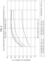
- Fig. 4 is a graph illustrating the relationship between the shape of the magnet and the maximum magnetic flux when the gap between the magnetic sensor 21 and the magnetic sensor 22 and the magnet 40 is 0.8 mm and the thickness (length in the Z direction) of the magnet 40 is 1.0 mm.
- the lines in Fig. 4 indicate the length of the magnet 40 in the Y direction. That is to say, Fig.
- the magnetic flux density becomes too low when the length of the magnet 40 in the X direction is less than 1.5 mm, but the magnetic flux density does not change greatly even when said length exceeds 3 mm.
- the length of the magnet 40 in the X direction is preferably 1.5 to 3 mm.
- the length of the magnet 40 in the Y direction is preferably 2 mm to 4 mm.
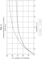
- Fig. 5 is a graph illustrating the relationship between the length of the magnet 40 in the Z direction (thickness) and magnetic flux density, when the lengths of the magnet 40 in the X direction and the Y direction are respectively 2mm by 3 mm, and 3 mm by 4 mm. As indicated by the graph in Fig.
- the magnetic flux density becomes too low when the thickness of the magnet 40 is less than 1 mm, but the magnetic flux density value does not change greatly even when said thickness exceeds 3 mm.
- the thickness of the magnet 40 is preferably 1 mm to 3 mm.
- the magnet 40 is preferably of a rectangular shape where the longitudinal direction is in the Y direction.
- FIG. 6 illustrates the positional relationship between a track displacement of the magnetic sensor 21 and the magnetic sensor 22 and the magnet 40, when the magnet 40 has a rectangular shape.
- the magnetic field of the magnet 40 has an elliptical shape with the Y direction as the longitudinal direction, and therefore the influence of track displacement is small.
- Fig. 7 is a graph illustrating the relationship between the displacement of the magnetic sensor 21 and the magnetic sensor 22 in the track direction and the output distribution, when the gap between the magnetic sensor 21 and the magnetic sensor 22 and the magnet 40 is 0.8 mm, and the lengths of the magnet 40 in the X direction, the Y direction, and the Z direction are respectively 3 mm, 4 mm, and 1 mm.
- the magnet 40 has a rectangular shape where the longitudinal direction is the Y direction, and in this case, even when the displacement in the track direction is 0.3 mm, the attenuation rate of the output is within a range of 2%. In view of this, it can be seen that the magnet 40 preferably has a rectangular shape where the longitudinal direction is the Y direction.
- the magnet 40 is preferably made of a material that is strong, is not susceptible to rusting, and has a favorable temperature coefficient. More specifically, a samarium-cobalt magnet having a temperature coefficient of -0.03%/°C, or a rust-proofed neodymium magnet having a temperature coefficient of -0.13%/°C, is preferable.
- the magnetic sensor 21 and the magnetic sensor 22 are preferably spaced apart by approximately 1.5 mm or more.
- the length of the magnet 40 in the X direction that allows for a maximum change rate of the outputs of the pair of the magnetic sensor 21 and the magnetic sensor 22 to be obtained is substantially equal to the mounting distance between the magnetic sensor 21 and the magnetic sensor 22, and therefore, as described above, when the magnetic sensor 21 and the magnetic sensor 22 are spaced apart by approximately 1.5 mm or more, the length of the magnet 40 in the X direction is preferably also approximately 1.5 mm or more.
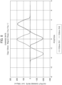
- FIG. 8 is a graph illustrating a relationship between the position of the magnet 40 and the output change rates of the magnetic sensor 21 and the magnetic sensor 22, when the gap between the pair of the magnetic sensor 21 and the magnetic sensor 22 and the magnet 40 is 0.8 mm, and the lengths of the magnet in the X direction, the Y direction, and the Z direction are respectively 3 mm, 4 mm, and 1 mm, and the length of the magnet 40 in the X direction is substantially equal to the mounting distance between the magnetic sensor 21 and the magnetic sensor 22.
- the position of the magnet 40 is 0, that is to say when the magnet 40 is positioned on the reference line, both of the absolute values of the output change rates of the magnetic sensor 21 and the magnetic sensor 22 are substantially maximum.
- the distance (gap) between the pair of the magnetic sensor 21 and the magnetic sensor 22 and the magnet 40 is determined by repeat precision, component precision, assembly precision, ease of assembly checking, etc. Specifically, it is determined with consideration to the required values of, for example, ⁇ 0.1 mm as the component precision, 0.2 mm as the mounting precision, and 0.1 mm or less as mechanical variation, that is to say, variations due to play in the shaft, etc. As a result, the distance (gap) between the pair of the magnetic sensors 21 and the magnet 40 is preferably 0.3 mm to 0.8 mm.
- Fig. 9 is a graph illustrating the relationship between the distance (gap) between the pair of the magnetic sensor 21 and the magnetic sensor 22 and the magnet 40, and the magnetic flux density.
- the distance (gap) is 0.3 mm to 0.8 mm, the magnetic flux density becomes generally 120 mT to 170 mT.
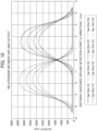
- Fig. 10 is a graph illustrating the relationship between a distance in the X direction centered on a detection point and the outputs, in cases where the distance (gap) between the pair of the magnetic sensor 21 and the magnetic sensor 22 and the magnet 40 is respectively 0.4 mm, 0.6 mm, 0.8 mm, and 1.0 mm.
- "Ch1" indicates the output of the magnetic sensor 21
- "Ch2" indicates the output of the magnetic sensor 22.
- the output is smaller compared to the other graphs.
- Fig. 11 is a graph illustrating the relationship between a distance in the X direction centered on a detection point and an actual value of the output change rate, in cases where the distance (gap) between the pair of the magnetic sensor 21 and the magnetic sensor 22 and the magnet 40 is respectively 0.4 mm, 0.6 mm, 0.8 mm, and 1.0 mm.
- "Ch1" indicates the output change rate of the magnetic sensor 21
- "Ch2" indicates the output change rate of the magnetic sensor 22.
- the absolute value of the output change rate is smaller compared to the other graphs.
- the state of the pair of the magnetic sensor 21 and the magnetic sensor 22 can be comprehended, allowing for a fault diagnosis of the position detection device 1. More specifically, by monitoring the internal data, it is possible to diagnose a maintenance time for the position detection device 1, diagnose faults in the pair of the magnetic sensor 21 and the magnetic sensor 22, and diagnose the operating environment of the position detection device 1.
- Fig. 12 illustrates an internal output using conventional contact points, wherein a contact 11 returns after being pushed in.
- Fig. 12 as indicated by numeral (a), the contact 11 is at a normal standby height during standby. Next, as indicated by numeral (b), the contact 11 is pushed in. Thereafter, when the load on the contact 11 is released, the contact 11 returns to the original position as indicated by numeral (c). At this time, the standby height of the contact 11 at (a) and the standby height of the contact 11 at (c) are equal, and thus the push-in amount of the contact 11 when going from (a) to (b) and the return amount of the contact 11 when going from (b) to (c) are equal. Further, regarding the value of the internal sensor, the value before pushing in the contact 11 and the value after the contact 11 has returned after being pushed in are equal.
- Fig. 13 illustrates a change in an internal sensor value as internal data when the position detection device 1 is in an abnormal state due to a return failure.
- cutting fluid and cutting chips have adhered to a region where the contact 11 of the position detection device 1 slides. Therefore, when going from (b) to (c), the contact 11 cannot return to the normal position. Accordingly, the return amount of the contact 11 when going from (b) to (c) is smaller than the push-in amount of the contact 11 when going from (a) to (b).
- the value after the contact 11 has returned after being pushed in is smaller than the value before pushing in the contact 11.
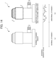
- Fig. 14 illustrates an internal sensor value as internal data when the position detection device 1 is in an abnormal state due to a deteriorated bearing.
- the value of the internal sensor does not fluctuate.
- the bearing has deteriorated
- a vibration and a vibration due to mounting or removal of a workpiece a vibration when moving the sensor into or out of storage, or an impact due to a pallet change has occurred
- the contact 11 vibrates accordingly, and, as indicated by numeral (b), the value of the internal sensor fluctuates.
- the position detection device 1 may further include a comparison unit (not illustrated) that compares the outputs of the magnetic sensor 21 and the magnetic sensor 22 during standby of the position detection device 1 with the outputs of the magnetic sensor 21 and the magnetic sensor 22 when the magnet 40 has been moved in the X direction and then returned in the direction opposite to the X direction, and a first diagnosis unit (not illustrated) that diagnoses an abnormality of the position detection device 1 on the basis of the comparison results from the comparison unit.
- a comparison unit (not illustrated) that compares the outputs of the magnetic sensor 21 and the magnetic sensor 22 during standby of the position detection device 1 with the outputs of the magnetic sensor 21 and the magnetic sensor 22 when the magnet 40 has been moved in the X direction and then returned in the direction opposite to the X direction
- a first diagnosis unit (not illustrated) that diagnoses an abnormality of the position detection device 1 on the basis of the comparison results from the comparison unit.
- the position detection device 1 may further include a second diagnosis unit (not illustrated) that diagnoses an abnormality of the position detection device 1 on the basis of the waveforms of the outputs of the magnetic sensor 21 and the magnetic sensor 22 during standby of the position detection device 1.
- a second diagnosis unit (not illustrated) that diagnoses an abnormality of the position detection device 1 on the basis of the waveforms of the outputs of the magnetic sensor 21 and the magnetic sensor 22 during standby of the position detection device 1.
- an aspect of the present invention provides a position detection device that can stably detect a position with high detection precision over a long lifespan.
- This position detection device is provided with a magnet configured to move, together with a movable body, on a movement path extending along a first direction.
- the magnet has different magnetic poles in a second direction that is perpendicular to the first direction.
- the position detection device is provided with a pair of magnetic sensors that are separated by equal distances, in the second direction, from the movement path, and that are disposed at equal distances from a reference line extending in the second direction.
- the pair of magnetic sensors have the same sensor characteristics.
- the position detection device is provided with a detection unit configured to detect that the magnet is positioned on the reference line in a state where the absolute values of the output change rates of both of the pair of magnetic sensors are substantially maximum.
- the position detection device is capable of detecting the position of the movable body without using mechanical contact points.
- the position detection device according to the present invention thus does not use any mechanical contact points, and therefore, there are no problems such as the lifespan being shortened or poor conductivity between contact points due to deterioration of the contact points, or the detection precision being reduced due to wear and denting of the contact points.
- changes in output characteristics of the pair of magnetic sensors due to temperature changes cancel each other out, and therefore, the position of the magnet can be stably detected.
- the outputs of the pair of magnetic sensors preferably exhibit the maximum change rates when the magnet is positioned on the reference line. According to this configuration, the outputs of the magnetic sensors easily change when the magnet is in the vicinity of the reference line, and therefore, the point at which the outputs of the magnetic sensors match each other is more precisely identified, and detection precision of the position of the magnet is increased.
- the present invention provides a position detection device that can stably detect a position with high detection precision over a long lifespan.
- the present invention provides a position detection device capable of fault diagnosis and predictive maintenance.
- the present invention is preferably used in a position detection device for detecting a position of a movable body.
Landscapes
- Physics & Mathematics (AREA)
- General Physics & Mathematics (AREA)
- Measurement Of Length, Angles, Or The Like Using Electric Or Magnetic Means (AREA)
- Transmission And Conversion Of Sensor Element Output (AREA)
Applications Claiming Priority (2)
| Application Number | Priority Date | Filing Date | Title |
|---|---|---|---|
| JP2020124015A JP7540698B2 (ja) | 2020-07-20 | 2020-07-20 | 位置検出装置 |
| PCT/JP2021/020416 WO2022018969A1 (ja) | 2020-07-20 | 2021-05-28 | 位置検出装置 |
Publications (4)
| Publication Number | Publication Date |
|---|---|
| EP4174445A1 true EP4174445A1 (de) | 2023-05-03 |
| EP4174445A4 EP4174445A4 (de) | 2023-12-06 |
| EP4174445C0 EP4174445C0 (de) | 2025-07-16 |
| EP4174445B1 EP4174445B1 (de) | 2025-07-16 |
Family
ID=79728641
Family Applications (1)
| Application Number | Title | Priority Date | Filing Date |
|---|---|---|---|
| EP21846287.7A Active EP4174445B1 (de) | 2020-07-20 | 2021-05-28 | Positionsdetektionsvorrichtung |
Country Status (4)
| Country | Link |
|---|---|
| EP (1) | EP4174445B1 (de) |
| JP (1) | JP7540698B2 (de) |
| CN (1) | CN115735099B (de) |
| WO (1) | WO2022018969A1 (de) |
Family Cites Families (15)
| Publication number | Priority date | Publication date | Assignee | Title |
|---|---|---|---|---|
| JPS6183710A (ja) * | 1984-09-29 | 1986-04-28 | Tsutomu Hino | コ−ン貫入試験機 |
| JP3582208B2 (ja) * | 1996-02-26 | 2004-10-27 | 松下電工株式会社 | 埋設物の位置検出装置 |
| JP2001221608A (ja) * | 2000-02-14 | 2001-08-17 | Ckd Corp | 回転位置検出装置及び回転位置決め装置 |
| US7355389B2 (en) * | 2005-11-01 | 2008-04-08 | Honeywell International, Inc. | Method and system for linear positioning |
| WO2007069680A1 (ja) * | 2005-12-16 | 2007-06-21 | Asahi Kasei Emd Corporation | 位置検出装置 |
| JP2008101932A (ja) * | 2006-10-17 | 2008-05-01 | Tokai Rika Co Ltd | 磁気式位置検出装置 |
| JP2008183699A (ja) | 2007-01-30 | 2008-08-14 | Metrol Ltd | 接触式位置センサ |
| JP4855454B2 (ja) * | 2008-10-14 | 2012-01-18 | 旭化成エレクトロニクス株式会社 | 位置検出装置及びその位置検出装置を用いた電子機器 |
| JP4985730B2 (ja) * | 2009-01-29 | 2012-07-25 | 株式会社デンソー | ストロークセンサおよび回転角センサ |
| JP5155966B2 (ja) * | 2009-08-12 | 2013-03-06 | 旭化成エレクトロニクス株式会社 | 位置検出装置 |
| JP5144694B2 (ja) * | 2010-02-17 | 2013-02-13 | 旭化成エレクトロニクス株式会社 | 磁気センサユニット |
| JP2011220832A (ja) * | 2010-04-09 | 2011-11-04 | Tokai Rika Co Ltd | 位置検出装置及びシフトレバー装置 |
| JP5646946B2 (ja) * | 2010-10-14 | 2014-12-24 | 旭化成エレクトロニクス株式会社 | 位置検出装置及びそれを備えた電子機器 |
| WO2016047782A1 (ja) * | 2014-09-26 | 2016-03-31 | 旭化成エレクトロニクス株式会社 | 磁気センサ |
| WO2020158677A1 (ja) * | 2019-01-31 | 2020-08-06 | 株式会社メトロール | 位置検出装置 |
-
2020
- 2020-07-20 JP JP2020124015A patent/JP7540698B2/ja active Active
-
2021
- 2021-05-28 EP EP21846287.7A patent/EP4174445B1/de active Active
- 2021-05-28 WO PCT/JP2021/020416 patent/WO2022018969A1/ja not_active Ceased
- 2021-05-28 CN CN202180046249.4A patent/CN115735099B/zh active Active
Also Published As
| Publication number | Publication date |
|---|---|
| JP7540698B2 (ja) | 2024-08-27 |
| EP4174445C0 (de) | 2025-07-16 |
| CN115735099A (zh) | 2023-03-03 |
| EP4174445A4 (de) | 2023-12-06 |
| WO2022018969A1 (ja) | 2022-01-27 |
| EP4174445B1 (de) | 2025-07-16 |
| JP2022020490A (ja) | 2022-02-01 |
| CN115735099B (zh) | 2025-09-26 |
Similar Documents
| Publication | Publication Date | Title |
|---|---|---|
| EP2820384B1 (de) | Verfahren zur berührungslosen messung einer relativen position mittels eines 3d hall-sensors mit messsignalsspeicherung | |
| EP3814076B1 (de) | Mehrachsiger kraft- und drehmomentsensor und roboter damit | |
| US9360537B2 (en) | Method for contactless measurement of a relative position by means of a hall sensor | |
| JP4589410B2 (ja) | 位置検出装置 | |
| CN106643467B (zh) | 旋转角度检测装置及其使用的角度传感器单元 | |
| US7595635B2 (en) | Small size magnetic encoder unit with low power consumption | |
| JP6275406B2 (ja) | 磁気エンコーダ装置および回転検出装置 | |
| US20200225061A1 (en) | Displacement detecting device and continuously variable transmission device | |
| EP1079122B1 (de) | Magnetlager | |
| US6441515B1 (en) | Linear motor | |
| EP4174445A1 (de) | Positionsdetektionsvorrichtung | |
| JP2673849B2 (ja) | 力検出手段付き直線運動用案内装置 | |
| EP4034842B1 (de) | Verdrängungsmessanordnung mit einem hall-sensor und einem magneten | |
| JP4926626B2 (ja) | 位置検出システム、位置検出システムを用いた光学系と撮像装置 | |
| CN109661521B (zh) | 异物检测装置及线性引导件 | |
| US10675723B1 (en) | Methods and apparatus for inserting a threaded fastener using a linear rotary actuator | |
| EP3913333B1 (de) | Positionsdetektionsvorrichtung | |
| KR102947389B1 (ko) | 리니어 반송 장치 및 리니어 반송 장치의 제조 방법 | |
| JP7592775B2 (ja) | ストロークセンサとこれを備えたストロークセンサ組立体 | |
| US20250155474A1 (en) | Method for manufacturing current sensor | |
| US20250067550A1 (en) | Magnetic sensor, method for designing the same, and assembly thereof | |
| Bratland et al. | Linear position sensing using magnetoresistive sensors | |
| CN121866446A (zh) | 编码器 | |
| CN118057114A (zh) | 行程传感器及具备其的行程传感器组件 | |
| JP2014151408A (ja) | 加工装置 |
Legal Events
| Date | Code | Title | Description |
|---|---|---|---|
| STAA | Information on the status of an ep patent application or granted ep patent |
Free format text: STATUS: THE INTERNATIONAL PUBLICATION HAS BEEN MADE |
|
| PUAI | Public reference made under article 153(3) epc to a published international application that has entered the european phase |
Free format text: ORIGINAL CODE: 0009012 |
|
| STAA | Information on the status of an ep patent application or granted ep patent |
Free format text: STATUS: REQUEST FOR EXAMINATION WAS MADE |
|
| 17P | Request for examination filed |
Effective date: 20230126 |
|
| AK | Designated contracting states |
Kind code of ref document: A1 Designated state(s): AL AT BE BG CH CY CZ DE DK EE ES FI FR GB GR HR HU IE IS IT LI LT LU LV MC MK MT NL NO PL PT RO RS SE SI SK SM TR |
|
| DAV | Request for validation of the european patent (deleted) | ||
| DAX | Request for extension of the european patent (deleted) | ||
| REG | Reference to a national code |
Ref country code: DE Ref legal event code: R079 Free format text: PREVIOUS MAIN CLASS: G01D0005244000 Ipc: H03K0017970000 Ref country code: DE Ref legal event code: R079 Ref document number: 602021034351 Country of ref document: DE Free format text: PREVIOUS MAIN CLASS: G01D0005244000 Ipc: H03K0017970000 |
|
| A4 | Supplementary search report drawn up and despatched |
Effective date: 20231103 |
|
| RIC1 | Information provided on ipc code assigned before grant |
Ipc: G01D 5/14 20060101ALI20231027BHEP Ipc: G01B 7/30 20060101ALI20231027BHEP Ipc: G01D 5/245 20060101ALI20231027BHEP Ipc: G01D 5/244 20060101ALI20231027BHEP Ipc: H03K 17/97 20060101AFI20231027BHEP |
|
| STAA | Information on the status of an ep patent application or granted ep patent |
Free format text: STATUS: EXAMINATION IS IN PROGRESS |
|
| 17Q | First examination report despatched |
Effective date: 20240726 |
|
| GRAP | Despatch of communication of intention to grant a patent |
Free format text: ORIGINAL CODE: EPIDOSNIGR1 |
|
| STAA | Information on the status of an ep patent application or granted ep patent |
Free format text: STATUS: GRANT OF PATENT IS INTENDED |
|
| INTG | Intention to grant announced |
Effective date: 20250314 |
|
| GRAS | Grant fee paid |
Free format text: ORIGINAL CODE: EPIDOSNIGR3 |
|
| GRAA | (expected) grant |
Free format text: ORIGINAL CODE: 0009210 |
|
| STAA | Information on the status of an ep patent application or granted ep patent |
Free format text: STATUS: THE PATENT HAS BEEN GRANTED |
|
| AK | Designated contracting states |
Kind code of ref document: B1 Designated state(s): AL AT BE BG CH CY CZ DE DK EE ES FI FR GB GR HR HU IE IS IT LI LT LU LV MC MK MT NL NO PL PT RO RS SE SI SK SM TR |
|
| REG | Reference to a national code |
Ref country code: GB Ref legal event code: FG4D |
|
| REG | Reference to a national code |
Ref country code: CH Ref legal event code: EP |
|
| REG | Reference to a national code |
Ref country code: IE Ref legal event code: FG4D |
|
| U01 | Request for unitary effect filed |
Effective date: 20250716 |
|
| U07 | Unitary effect registered |
Designated state(s): AT BE BG DE DK EE FI FR IT LT LU LV MT NL PT RO SE SI Effective date: 20250722 |
|
| PG25 | Lapsed in a contracting state [announced via postgrant information from national office to epo] |
Ref country code: IS Free format text: LAPSE BECAUSE OF FAILURE TO SUBMIT A TRANSLATION OF THE DESCRIPTION OR TO PAY THE FEE WITHIN THE PRESCRIBED TIME-LIMIT Effective date: 20251116 |
|
| PG25 | Lapsed in a contracting state [announced via postgrant information from national office to epo] |
Ref country code: NO Free format text: LAPSE BECAUSE OF FAILURE TO SUBMIT A TRANSLATION OF THE DESCRIPTION OR TO PAY THE FEE WITHIN THE PRESCRIBED TIME-LIMIT Effective date: 20251016 |
|
| PG25 | Lapsed in a contracting state [announced via postgrant information from national office to epo] |
Ref country code: HR Free format text: LAPSE BECAUSE OF FAILURE TO SUBMIT A TRANSLATION OF THE DESCRIPTION OR TO PAY THE FEE WITHIN THE PRESCRIBED TIME-LIMIT Effective date: 20250716 |
|
| PG25 | Lapsed in a contracting state [announced via postgrant information from national office to epo] |
Ref country code: GR Free format text: LAPSE BECAUSE OF FAILURE TO SUBMIT A TRANSLATION OF THE DESCRIPTION OR TO PAY THE FEE WITHIN THE PRESCRIBED TIME-LIMIT Effective date: 20251017 |
|
| PG25 | Lapsed in a contracting state [announced via postgrant information from national office to epo] |
Ref country code: PL Free format text: LAPSE BECAUSE OF FAILURE TO SUBMIT A TRANSLATION OF THE DESCRIPTION OR TO PAY THE FEE WITHIN THE PRESCRIBED TIME-LIMIT Effective date: 20250716 |
|
| PG25 | Lapsed in a contracting state [announced via postgrant information from national office to epo] |
Ref country code: RS Free format text: LAPSE BECAUSE OF FAILURE TO SUBMIT A TRANSLATION OF THE DESCRIPTION OR TO PAY THE FEE WITHIN THE PRESCRIBED TIME-LIMIT Effective date: 20251016 |
|
| PG25 | Lapsed in a contracting state [announced via postgrant information from national office to epo] |
Ref country code: ES Free format text: LAPSE BECAUSE OF FAILURE TO SUBMIT A TRANSLATION OF THE DESCRIPTION OR TO PAY THE FEE WITHIN THE PRESCRIBED TIME-LIMIT Effective date: 20250716 |
|
| PG25 | Lapsed in a contracting state [announced via postgrant information from national office to epo] |
Ref country code: SM Free format text: LAPSE BECAUSE OF FAILURE TO SUBMIT A TRANSLATION OF THE DESCRIPTION OR TO PAY THE FEE WITHIN THE PRESCRIBED TIME-LIMIT Effective date: 20250716 |
|
| PG25 | Lapsed in a contracting state [announced via postgrant information from national office to epo] |
Ref country code: CZ Free format text: LAPSE BECAUSE OF FAILURE TO SUBMIT A TRANSLATION OF THE DESCRIPTION OR TO PAY THE FEE WITHIN THE PRESCRIBED TIME-LIMIT Effective date: 20250716 |
|
| PG25 | Lapsed in a contracting state [announced via postgrant information from national office to epo] |
Ref country code: SK Free format text: LAPSE BECAUSE OF FAILURE TO SUBMIT A TRANSLATION OF THE DESCRIPTION OR TO PAY THE FEE WITHIN THE PRESCRIBED TIME-LIMIT Effective date: 20250716 |