US9360537B2 - Method for contactless measurement of a relative position by means of a hall sensor - Google Patents

Method for contactless measurement of a relative position by means of a hall sensor Download PDF

Info

Publication number
US9360537B2
US9360537B2 US14/348,029 US201214348029A US9360537B2 US 9360537 B2 US9360537 B2 US 9360537B2 US 201214348029 A US201214348029 A US 201214348029A US 9360537 B2 US9360537 B2 US 9360537B2
Authority
US
United States
Prior art keywords
magnetic field
sensor
value
movement direction
source
Prior art date
Legal status (The legal status is an assumption and is not a legal conclusion. Google has not performed a legal analysis and makes no representation as to the accuracy of the status listed.)
Active, expires
Application number
US14/348,029
Other versions
US20140239942A1 (en
Inventor
Oliver Schaaf
Current Assignee (The listed assignees may be inaccurate. Google has not performed a legal analysis and makes no representation or warranty as to the accuracy of the list.)
TE Connectivity Germany GmbH
Original Assignee
TE Connectivity Germany GmbH
Priority date (The priority date is an assumption and is not a legal conclusion. Google has not performed a legal analysis and makes no representation as to the accuracy of the date listed.)
Filing date
Publication date
Application filed by TE Connectivity Germany GmbH filed Critical TE Connectivity Germany GmbH
Assigned to TYCO ELECTRONICS AMP GMBH reassignment TYCO ELECTRONICS AMP GMBH ASSIGNMENT OF ASSIGNORS INTEREST (SEE DOCUMENT FOR DETAILS). Assignors: SCHAAF, OLIVER
Publication of US20140239942A1 publication Critical patent/US20140239942A1/en
Assigned to TE CONNECTIVITY GERMANY GMBH reassignment TE CONNECTIVITY GERMANY GMBH CHANGE OF NAME (SEE DOCUMENT FOR DETAILS). Assignors: TYCO ELECTRONICS AMP GMBH
Application granted granted Critical
Publication of US9360537B2 publication Critical patent/US9360537B2/en
Active legal-status Critical Current
Adjusted expiration legal-status Critical

Links

Images

Classifications

    • GPHYSICS
    • G01MEASURING; TESTING
    • G01RMEASURING ELECTRIC VARIABLES; MEASURING MAGNETIC VARIABLES
    • G01R33/00Arrangements or instruments for measuring magnetic variables
    • G01R33/02Measuring direction or magnitude of magnetic fields or magnetic flux
    • G01R33/06Measuring direction or magnitude of magnetic fields or magnetic flux using galvano-magnetic devices
    • G01R33/07Hall effect devices
    • GPHYSICS
    • G01MEASURING; TESTING
    • G01BMEASURING LENGTH, THICKNESS OR SIMILAR LINEAR DIMENSIONS; MEASURING ANGLES; MEASURING AREAS; MEASURING IRREGULARITIES OF SURFACES OR CONTOURS
    • G01B7/00Measuring arrangements characterised by the use of electric or magnetic techniques
    • G01B7/14Measuring arrangements characterised by the use of electric or magnetic techniques for measuring distance or clearance between spaced objects or spaced apertures
    • GPHYSICS
    • G01MEASURING; TESTING
    • G01DMEASURING NOT SPECIALLY ADAPTED FOR A SPECIFIC VARIABLE; ARRANGEMENTS FOR MEASURING TWO OR MORE VARIABLES NOT COVERED IN A SINGLE OTHER SUBCLASS; TARIFF METERING APPARATUS; MEASURING OR TESTING NOT OTHERWISE PROVIDED FOR
    • G01D5/00Mechanical means for transferring the output of a sensing member; Means for converting the output of a sensing member to another variable where the form or nature of the sensing member does not constrain the means for converting; Transducers not specially adapted for a specific variable
    • G01D5/12Mechanical means for transferring the output of a sensing member; Means for converting the output of a sensing member to another variable where the form or nature of the sensing member does not constrain the means for converting; Transducers not specially adapted for a specific variable using electric or magnetic means
    • G01D5/14Mechanical means for transferring the output of a sensing member; Means for converting the output of a sensing member to another variable where the form or nature of the sensing member does not constrain the means for converting; Transducers not specially adapted for a specific variable using electric or magnetic means influencing the magnitude of a current or voltage
    • G01D5/142Mechanical means for transferring the output of a sensing member; Means for converting the output of a sensing member to another variable where the form or nature of the sensing member does not constrain the means for converting; Transducers not specially adapted for a specific variable using electric or magnetic means influencing the magnitude of a current or voltage using Hall-effect devices
    • G01D5/145Mechanical means for transferring the output of a sensing member; Means for converting the output of a sensing member to another variable where the form or nature of the sensing member does not constrain the means for converting; Transducers not specially adapted for a specific variable using electric or magnetic means influencing the magnitude of a current or voltage using Hall-effect devices influenced by the relative movement between the Hall device and magnetic fields
    • GPHYSICS
    • G01MEASURING; TESTING
    • G01DMEASURING NOT SPECIALLY ADAPTED FOR A SPECIFIC VARIABLE; ARRANGEMENTS FOR MEASURING TWO OR MORE VARIABLES NOT COVERED IN A SINGLE OTHER SUBCLASS; TARIFF METERING APPARATUS; MEASURING OR TESTING NOT OTHERWISE PROVIDED FOR
    • G01D5/00Mechanical means for transferring the output of a sensing member; Means for converting the output of a sensing member to another variable where the form or nature of the sensing member does not constrain the means for converting; Transducers not specially adapted for a specific variable
    • G01D5/12Mechanical means for transferring the output of a sensing member; Means for converting the output of a sensing member to another variable where the form or nature of the sensing member does not constrain the means for converting; Transducers not specially adapted for a specific variable using electric or magnetic means
    • G01D5/244Mechanical means for transferring the output of a sensing member; Means for converting the output of a sensing member to another variable where the form or nature of the sensing member does not constrain the means for converting; Transducers not specially adapted for a specific variable using electric or magnetic means influencing characteristics of pulses or pulse trains; generating pulses or pulse trains
    • G01D5/24471Error correction
    • G01D5/2448Correction of gain, threshold, offset or phase control

Definitions

  • the present invention relates to a method for contactless measurement of a relative position of a magnetic field source which produces a magnetic field and a magnetic field sensor in relation to each other. Furthermore, the present invention also relates to a corresponding displacement sensor.
  • linear movements are intended to be detected and evaluated by means of the method according to the invention in a contactless manner by means of magnetic interaction between one or more permanent magnets and a magnetic sensor based on the Hall effect.
  • the measurement of linear movements is used, for example, for controlling machine tools, in pneumatics, in automation technology and robotics as well as in the automotive sector.
  • Contactless detection of movements affords inter alia the advantage of freedom from wear.
  • optical and magnetic methods are most widespread. Whereas the optical methods ensure a very high level of precision owing to the short wavelength of the light, magnetic methods are far less sensitive with respect to contamination and damage, in particular in that magnets and sensor components can be completely enclosed in a non-magnetic hermetic casing.
  • Displacement sensor systems in which the position of a displaceable permanent magnet is established by means of a two-dimensional or three-dimensional Hall sensor are marketed by various manufacturers.
  • this principle has the advantage that it is comparatively not very sensitive with respect to a change in the absolute magnetic field strength because proportional numbers between the field components are used to detect the position.
  • European patent specification EP0979988 B1 discloses measurement methods for contactless magnetic detection of relative linear movements between permanent magnets and electronic sensors. In order to detect the relative linear movements by means of the electronic sensors, two mutually perpendicular field components whose quotient is evaluated to establish the position are detected.
  • the known measurement method can also be carried out so that two mutually perpendicular field components whose quotient is evaluated to establish the position are detected at two locations in order to detect the relative linear movements by means of the electronic sensors.
  • the published European patent application EP2159546 A2 discloses a measurement method for contactless detection of relative linear movements between a sensor arrangement for detecting two mutually perpendicular magnetic field components (R, A) and a permanent magnet.
  • a two-dimensional or three-dimensional Hall sensor is used in place of individual sensors in order to detect different field components.
  • the published European patent application EP1243897 A1 relates to a magnetic displacement sensor which comprises a magnetic field source and a magnetic field sensor which can be displaced relative to each other along a predetermined path.
  • the magnetic field sensor measures two components of the magnetic field produced by the magnetic field source.
  • a position signal which represents the relative position of the magnetic field sensor and the magnetic field source is then derived from the measured components.
  • the configurations of the displacement sensor shown in this specification are distinguished in that the determination of the position signal contains a division of the two measured components of the magnetic field.
  • FIG. 1 shows an arrangement in which a Hall sensor 100 is fitted so as to be fixed in position in order to contactlessly detect a linear movement and detects the magnetic field of a movable permanent magnet 102 .
  • the magnetic field extending in the direction of movement is referred to below as the magnetic field component Bz and the component extending transversely thereto is referred to as the component By.
  • the angle ⁇ which can be calculated in accordance with the following equation (1) is generally used as the measurement signal.
  • the angle ⁇ is dependent in a comparatively linear manner on the position of the permanent magnet 102 in relation to the Hall sensor 100 up to a given threshold value.
  • the characteristic line currently being measured is further linearised, as illustrated in FIG. 2 by means of the line 104 . That linearised line ⁇ _lin 104 then forms the characteristic output line of the sensor.
  • FIG. 3 the groups of lines for the magnetic field components By and Bz are indicated with different spacings b as parameters.
  • the line having the smallest magnetic field in terms of value is the one having the greatest spacing (in this instance, 7 mm), respectively. If the angle is calculated from those field components by means of its dependence on the position of the permanent magnet, the path illustrated in FIG. 4 is obtained.
  • the characteristic lines are subtracted one from the other and the percentage error is set out. The dependence illustrated in FIG. 5 is produced as a result.
  • the line 106 represents the error between the lines for a spacing of 7 mm and the line for a spacing of 6.5 mm, whilst the line 108 represents the difference between the angle ⁇ for a spacing of 6.5 mm and the angle for a spacing of 5.5 mm. That is to say, a spacing variation of 1 mm results in a deviation of 1.6% and a spacing variation of 1.5 mm results in a deviation of 2.3%.
  • An object of the present invention is to improve a measurement method and a displacement sensor of the type mentioned so that as linear a measurement signal as possible is produced over as wide a measurement range as possible and is influenced as little as possible by variations in spacing between the magnetic field source and the magnetic field sensor.
  • the present invention is based on the notion of not using the value for the field component in the movement direction directly in the arc tangent calculation, but instead to expand this term by a correction value. That offset value results in gradient adaptation of lines for the angle ⁇ at different spacings d.
  • FIG. 1 shows a displacement sensor whose signal can be evaluated according to the present invention
  • FIG. 2 shows the path of the magnetic field components produced in accordance with the position of the permanent magnet and the non-corrected angle ⁇ calculated therefrom;
  • FIG. 3 shows the field components produced by the permanent magnet in the y direction and z direction in accordance with the spacing between the permanent magnet and the magnetic field sensor;
  • FIG. 4 shows the angle ⁇ as a function of the position of the permanent magnet for different spacings d;
  • FIG. 5 shows the relative error in accordance with the spacing between the permanent magnet and the magnetic field sensor
  • FIG. 6 shows the explanation of the calculation provisions for the correction according to the invention
  • FIG. 7 shows the path of the corrected angle ⁇ in accordance with the spacing between the permanent magnet and the magnetic field sensor
  • FIG. 8 shows the relative error in accordance with the position for different spacings
  • FIG. 9 shows the two lines from FIG. 8 to an enlarged scale
  • FIG. 10 shows the path of the measured and corrected magnetic field components in accordance with the position
  • FIG. 11 shows the path of the magnetic field component which extends parallel with the change in position and the first derivative thereof
  • FIG. 12 shows a displacement sensor arrangement according to a second embodiment
  • FIG. 13 shows a displacement sensor arrangement according to a third embodiment
  • FIG. 14 shows a displacement sensor arrangement according to a fourth embodiment
  • FIG. 15 is an illustration of the characteristic lines for a variation in spacing between the magnet and the sensor for the conventional calculation provisions
  • FIG. 16 shows the path of the characteristic lines for the arrangement according to FIG. 1 when the correction according to the invention is used.
  • FIG. 1 A displacement sensor arrangement according to a first embodiment is shown in FIG. 1 .
  • a Hall sensor 100 is mounted so as to be fixed in position and a permanent magnet 102 is supported so as to be linearly movable in relation to the Hall sensor 100 .
  • the permanent magnet 102 has such a pole configuration that its north/south axis is orientated parallel with the movement direction. In principle, however, it is also possible to use the principles of the present invention for arrangements in which the permanent magnet 102 has such a pole configuration that its north/south axis extends transversely relative to the movement direction.
  • the permanent magnet 102 can be displaced out of the zero position shown in FIG. 1 in two directions by, for example, approximately 25 mm.
  • the Hall sensor 100 detects at least two orthogonal magnetic field components—one which extends along the movement line and one which extends transversely relative thereto. Vector addition of the two components provides the value of the magnetic field
  • the angle ⁇ is defined as the angle which is enclosed by the total magnetic field vector
  • the angle ⁇ is calculated from the magnetic field components in or transversely to the movement direction according to equation (1):
  • FIG. 6 shows the measurement signals which are measured in accordance with the position of the permanent magnet 102 of the magnetic field sensor, in this instance a Hall sensor 100 .
  • These are, on the one hand, the values of the magnetic field in the movement direction Bz and, on the other hand, the values of the magnetic field transverse relative to the movement direction By.
  • the values Bx which extend orthogonally to By for the calculation.
  • the arc tangent of the quotient Bz to By according to equation (1) is not used as the measurement signal but instead the magnetic field component Bz which extends in the movement direction is corrected by means of an offset value. That offset results in a gradient adaptation.
  • equation (2) is produced for the calculation of the angle ⁇ :
  • ⁇ _OS arctan ⁇ ( Bz + OS By ) ( 2 )
  • the corrected Bz+OS line is designated 110 in FIG. 6 .
  • the influence of the spacing d on the measurement signal is substantially smaller in this instance. It can be seen that a variation in spacing of 1 mm results in a deviation of less than 0.3% and a variation in spacing of 1.5 mm also results in a deviation of less than 0.3%.
  • the spacing dependence of the output signal is reduced to approximately 1 ⁇ 8 with respect to the uncorrected evaluation.
  • the computational establishment of that value is intended to be explained in greater detail below with reference to FIGS. 10 and 11 .
  • FIG. 10 shows the paths for the orthogonal magnetic field components By and Bz in accordance with the position of the permanent magnet 102 and the derivative of the field component along the movement to the position x. It can be seen that the optimum for the term OS is achieved when the point of inflection of Bz is equal to zero, that is to say, when the second derivative is zero or the gradient of the line 112 shown is horizontal.
  • offset value does not necessarily have to be added to the field component in a computational manner but instead may also be produced physically by another auxiliary magnet 114 because a constant factor is always added in the method according to the invention.
  • the auxiliary magnet 114 may be arranged in a plane which has the same spacing d from the movable permanent magnet as the Hall sensor 100 (see FIGS. 12 and 13 ). Owing to the auxiliary magnet 114 , a magnetic field component which ensures the necessary correction according to equation (2) is produced in the movement direction Bz_OS.
  • auxiliary magnet 114 may also be mounted on the rear side of a circuit carrier, for example, a printed circuit board, PCB, 116 , on the other side of which the Hall sensor 100 is constructed. This embodiment is schematically indicated in FIG. 14 .
  • the hardware solution using an auxiliary magnet 114 has the advantage that the calculation provision may be carried out in an unchanged state according to equation (1) but nevertheless the improved level of precision is achieved.
  • FIG. 15 shows the output signal of the sensor in accordance with the displacement of the permanent magnet for different distances d between the magnet and the sensor as a parameter.
  • the different gradient values in accordance with the variation in spacing can clearly be seen. If, however, the value of the difference between the maximum of the corresponding magnetic field component and the value at the point of inflection is calculated as above with reference to FIG. 11 , an offset of 14.7 mT is obtained. If the value corrected by the value 14.7 mT is used in place of the uncorrected magnetic field component for the arc tangent calculation, the group of lines of FIG. 16 is produced in comparison with the group of characteristic lines of FIG. 15 which are greatly dependent on spacing.
  • REFERENCE NUMERALS 100 Hall sensor 102 Permanent magnet 104 Line progression ⁇ _lin 106 Line progression ⁇ _7.0 mm - ⁇ _6.5 mm 108 Line progression ⁇ _6.5 mm - ⁇ _5.5 mm 110 Line progression Bz + OS 112 Line progression ⁇ _OS 114 Auxiliary magnet 116 Circuit carrier (PCB) 118 Line progression ⁇ _OS_7.0 mm - ⁇ _OS_6.5 mm 120 Line progression ⁇ _OS_6.5 mm - ⁇ _OS_5.5 mm
  • PCB Circuit carrier

Landscapes

  • Physics & Mathematics (AREA)
  • General Physics & Mathematics (AREA)
  • Condensed Matter Physics & Semiconductors (AREA)
  • Transmission And Conversion Of Sensor Element Output (AREA)
  • Measurement Of Length, Angles, Or The Like Using Electric Or Magnetic Means (AREA)

Abstract

The present invention relates to a method for contactless measurement of a relative position of a magnetic field source, which produces a magnetic field and a magnetic field sensor in relation to each other. The present invention further relates to a corresponding displacement sensor. According to the present invention, the magnetic field sensor detects at least two spatial components (Bz, By) of the magnetic field and a position signal is produced from the measured components. The method comprises the following steps of calculating the position signal based on a quotient of the two magnetic field components; and correcting, before the quotient is calculated, the magnetic field component, which extends in a movement direction between the magnetic field source and the magnetic field sensor.

Description

BACKGROUND
The present invention relates to a method for contactless measurement of a relative position of a magnetic field source which produces a magnetic field and a magnetic field sensor in relation to each other. Furthermore, the present invention also relates to a corresponding displacement sensor.
In particular, linear movements are intended to be detected and evaluated by means of the method according to the invention in a contactless manner by means of magnetic interaction between one or more permanent magnets and a magnetic sensor based on the Hall effect.
The measurement of linear movements is used, for example, for controlling machine tools, in pneumatics, in automation technology and robotics as well as in the automotive sector. Contactless detection of movements affords inter alia the advantage of freedom from wear. Among the contactless measuring methods, optical and magnetic methods are most widespread. Whereas the optical methods ensure a very high level of precision owing to the short wavelength of the light, magnetic methods are far less sensitive with respect to contamination and damage, in particular in that magnets and sensor components can be completely enclosed in a non-magnetic hermetic casing.
Displacement sensor systems in which the position of a displaceable permanent magnet is established by means of a two-dimensional or three-dimensional Hall sensor are marketed by various manufacturers.
In order to detect the relative linear movements at a location, two magnetic field components which are perpendicular to each other are measured and their quotient is evaluated in order to determine the position. This method has the advantage that, in regions in which a field component takes up an extreme value and therefore does not detect small displacements, the other field component reacts all the more strongly to displacements so that an approximately identically high level of measurement precision is provided over the entire measurement range.
Furthermore, this principle has the advantage that it is comparatively not very sensitive with respect to a change in the absolute magnetic field strength because proportional numbers between the field components are used to detect the position.
European patent specification EP0979988 B1 discloses measurement methods for contactless magnetic detection of relative linear movements between permanent magnets and electronic sensors. In order to detect the relative linear movements by means of the electronic sensors, two mutually perpendicular field components whose quotient is evaluated to establish the position are detected.
In a second method variant, the known measurement method can also be carried out so that two mutually perpendicular field components whose quotient is evaluated to establish the position are detected at two locations in order to detect the relative linear movements by means of the electronic sensors.
The published European patent application EP2159546 A2 discloses a measurement method for contactless detection of relative linear movements between a sensor arrangement for detecting two mutually perpendicular magnetic field components (R, A) and a permanent magnet. A two-dimensional or three-dimensional Hall sensor is used in place of individual sensors in order to detect different field components. The quasi-linear position measurement line is formed by the function U=y−e+g, where y is the functional relationship of the field components and e and g are predeterminable voltage values. In particular, a quasi-linear position measurement line U=f(y) is formed from the output signals of the Hall sensor according to the relationship y=a+b·R/f(c·Rn+d·An), where R is the radial field component, A is the axial field component, U is the measurement voltage and a, b, c, d and n are constant factors.
The published European patent application EP1243897 A1 relates to a magnetic displacement sensor which comprises a magnetic field source and a magnetic field sensor which can be displaced relative to each other along a predetermined path. The magnetic field sensor measures two components of the magnetic field produced by the magnetic field source. A position signal which represents the relative position of the magnetic field sensor and the magnetic field source is then derived from the measured components. The configurations of the displacement sensor shown in this specification are distinguished in that the determination of the position signal contains a division of the two measured components of the magnetic field.
However, those known methods have the disadvantage that the spacing between the permanent magnet and the magnetic sensor constitutes a significant error source in the measurement. It is often very difficult to keep that spacing constant, particularly owing to assembly tolerances, thermally induced material expansion and vibration influences.
FIG. 1 shows an arrangement in which a Hall sensor 100 is fitted so as to be fixed in position in order to contactlessly detect a linear movement and detects the magnetic field of a movable permanent magnet 102. In accordance with the north/south polarisation in the direction of movement of the permanent magnet 102, the magnetic field extending in the direction of movement is referred to below as the magnetic field component Bz and the component extending transversely thereto is referred to as the component By. The angle α, which can be calculated in accordance with the following equation (1) is generally used as the measurement signal.
α = arc tan ( Bz By ) ( 1 )
As illustrated in FIG. 2, the angle α is dependent in a comparatively linear manner on the position of the permanent magnet 102 in relation to the Hall sensor 100 up to a given threshold value. Usually, the characteristic line currently being measured is further linearised, as illustrated in FIG. 2 by means of the line 104. That linearised line α_lin 104 then forms the characteristic output line of the sensor.
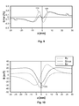
With reference to FIGS. 3 and 4, the dependence of the output signal on the spacing d between the permanent magnet 102 and the sensor 100 is explained in greater detail (see FIG. 1).
In FIG. 3, the groups of lines for the magnetic field components By and Bz are indicated with different spacings b as parameters. The line having the smallest magnetic field in terms of value is the one having the greatest spacing (in this instance, 7 mm), respectively. If the angle is calculated from those field components by means of its dependence on the position of the permanent magnet, the path illustrated in FIG. 4 is obtained. In order to illustrate how great the gradient error is, the characteristic lines are subtracted one from the other and the percentage error is set out. The dependence illustrated in FIG. 5 is produced as a result.
The line 106 represents the error between the lines for a spacing of 7 mm and the line for a spacing of 6.5 mm, whilst the line 108 represents the difference between the angle α for a spacing of 6.5 mm and the angle for a spacing of 5.5 mm. That is to say, a spacing variation of 1 mm results in a deviation of 1.6% and a spacing variation of 1.5 mm results in a deviation of 2.3%.
However, this is not acceptable for very sensitive systems such as, for example, an assisted steering system or a pedal travel measurement in a motor vehicle, so that there is a need for an improved signal processing operation which is less sensitive with respect to an undesirable variation of the spacing between the permanent magnet and the Hall sensor element.
SUMMARY
An object of the present invention is to improve a measurement method and a displacement sensor of the type mentioned so that as linear a measurement signal as possible is produced over as wide a measurement range as possible and is influenced as little as possible by variations in spacing between the magnetic field source and the magnetic field sensor.
This object is achieved by the subject-matter of the independent patent claims. The dependent claims relate to advantageous developments of the method and displacement sensor according to the invention.
The present invention is based on the notion of not using the value for the field component in the movement direction directly in the arc tangent calculation, but instead to expand this term by a correction value. That offset value results in gradient adaptation of lines for the angle α at different spacings d.
Since this is a comparatively simple calculation operation, it is possible to improve the precision of a displacement sensor in accordance with the generic type in an extremely simple manner.
For a better understanding of the present invention, it is explained in greater detail with reference to the embodiments illustrated in the following Figures. Identical components are indicated with identical reference numerals and identical component designations.
Furthermore, individual features or combinations of features from the embodiments shown and described may also constitute independent inventive solutions or solutions according to the invention separately.
BRIEF DESCRIPTION OF THE DRAWINGS
In the drawings:
FIG. 1 shows a displacement sensor whose signal can be evaluated according to the present invention;
FIG. 2 shows the path of the magnetic field components produced in accordance with the position of the permanent magnet and the non-corrected angle α calculated therefrom;
FIG. 3 shows the field components produced by the permanent magnet in the y direction and z direction in accordance with the spacing between the permanent magnet and the magnetic field sensor;
FIG. 4 shows the angle α as a function of the position of the permanent magnet for different spacings d;
FIG. 5 shows the relative error in accordance with the spacing between the permanent magnet and the magnetic field sensor;
FIG. 6 shows the explanation of the calculation provisions for the correction according to the invention;
FIG. 7 shows the path of the corrected angle α in accordance with the spacing between the permanent magnet and the magnetic field sensor;
FIG. 8 shows the relative error in accordance with the position for different spacings;
FIG. 9 shows the two lines from FIG. 8 to an enlarged scale;
FIG. 10 shows the path of the measured and corrected magnetic field components in accordance with the position;
FIG. 11 shows the path of the magnetic field component which extends parallel with the change in position and the first derivative thereof;
FIG. 12 shows a displacement sensor arrangement according to a second embodiment;
FIG. 13 shows a displacement sensor arrangement according to a third embodiment;
FIG. 14 shows a displacement sensor arrangement according to a fourth embodiment;
FIG. 15 is an illustration of the characteristic lines for a variation in spacing between the magnet and the sensor for the conventional calculation provisions;
FIG. 16 shows the path of the characteristic lines for the arrangement according to FIG. 1 when the correction according to the invention is used.
DETAILED DESCRIPTION
The invention is intended to be explained in greater detail below initially with reference to FIG. 6 and FIG. 1.
A displacement sensor arrangement according to a first embodiment is shown in FIG. 1. A Hall sensor 100 is mounted so as to be fixed in position and a permanent magnet 102 is supported so as to be linearly movable in relation to the Hall sensor 100. The permanent magnet 102 has such a pole configuration that its north/south axis is orientated parallel with the movement direction. In principle, however, it is also possible to use the principles of the present invention for arrangements in which the permanent magnet 102 has such a pole configuration that its north/south axis extends transversely relative to the movement direction. The permanent magnet 102 can be displaced out of the zero position shown in FIG. 1 in two directions by, for example, approximately 25 mm. The Hall sensor 100 detects at least two orthogonal magnetic field components—one which extends along the movement line and one which extends transversely relative thereto. Vector addition of the two components provides the value of the magnetic field |B|. The angle α is defined as the angle which is enclosed by the total magnetic field vector |B| with the line perpendicular to the direction of movement.
As already mentioned, the angle α is calculated from the magnetic field components in or transversely to the movement direction according to equation (1):
α = arc tan ( Bz By ) ( 1 )
Naturally, it is also possible to transfer the principles according to the invention to other magnetic field sources, for example, electromagnets, and to other magnetic field sensors, such as magnetoresistive sensors or inductive sensors.
FIG. 6 shows the measurement signals which are measured in accordance with the position of the permanent magnet 102 of the magnetic field sensor, in this instance a Hall sensor 100. These are, on the one hand, the values of the magnetic field in the movement direction Bz and, on the other hand, the values of the magnetic field transverse relative to the movement direction By. Naturally, it is also possible to use the values Bx which extend orthogonally to By for the calculation.
According to the invention, the arc tangent of the quotient Bz to By according to equation (1) is not used as the measurement signal but instead the magnetic field component Bz which extends in the movement direction is corrected by means of an offset value. That offset results in a gradient adaptation. The following equation (2) is produced for the calculation of the angle α:
α_OS = arctan ( Bz + OS By ) ( 2 )
The corrected Bz+OS line is designated 110 in FIG. 6.
If the line progression of the corrected angle α_OS is now considered in FIG. 7 for different spacings d, it is evident that the progression of the line is substantially less dependent on a variation of the spacing d which is indicated here as a parameter for the group of lines.
This means that, on the one hand, assembly tolerances can be taken up with the solution according to the invention but, on the other hand, influences owing to vibrations can also be prevented.
The lines of FIGS. 8 and 9 show the corresponding relative errors of the angle α_OS for d=7 mm in comparison with d=6.5 mm (the line 118 indicates the relative error of α_OS_7.0 mm-α_OS_6.5 mm) and for d=6.5 mm and d=5.5 mm (the line 120 indicates the relative error of α_OS_6.5 mm-α_OS_5.5 mm) in relation to the higher value in each case.
In comparison with the lines of FIG. 5, the influence of the spacing d on the measurement signal is substantially smaller in this instance. It can be seen that a variation in spacing of 1 mm results in a deviation of less than 0.3% and a variation in spacing of 1.5 mm also results in a deviation of less than 0.3%.
Owing to the correction according to the invention, the spacing dependence of the output signal is reduced to approximately ⅛ with respect to the uncorrected evaluation.
The correction value used in FIG. 6 is OS=14.7 mT. The computational establishment of that value is intended to be explained in greater detail below with reference to FIGS. 10 and 11.
In FIG. 10, the paths for the orthogonal magnetic field components By and Bz are indicated, FIG. 11 shows the line Bz in accordance with the position of the permanent magnet 102 and the derivative of the field component along the movement to the position x. It can be seen that the optimum for the term OS is achieved when the point of inflection of Bz is equal to zero, that is to say, when the second derivative is zero or the gradient of the line 112 shown is horizontal.
The difference between the maximum value for Bz and the value at the location d2Bz/dz2=0 results in an offset value of OS=14.7 mT for the embodiment shown in FIG. 1.
However, that offset value does not necessarily have to be added to the field component in a computational manner but instead may also be produced physically by another auxiliary magnet 114 because a constant factor is always added in the method according to the invention.
The auxiliary magnet 114 may be arranged in a plane which has the same spacing d from the movable permanent magnet as the Hall sensor 100 (see FIGS. 12 and 13). Owing to the auxiliary magnet 114, a magnetic field component which ensures the necessary correction according to equation (2) is produced in the movement direction Bz_OS.
Alternatively, however, the auxiliary magnet 114 may also be mounted on the rear side of a circuit carrier, for example, a printed circuit board, PCB, 116, on the other side of which the Hall sensor 100 is constructed. This embodiment is schematically indicated in FIG. 14.
The hardware solution using an auxiliary magnet 114 has the advantage that the calculation provision may be carried out in an unchanged state according to equation (1) but nevertheless the improved level of precision is achieved.
The advantageous effect of the solution according to the invention can be shown directly by a comparison of FIGS. 15 and 16.
FIG. 15 shows the output signal of the sensor in accordance with the displacement of the permanent magnet for different distances d between the magnet and the sensor as a parameter. The different gradient values in accordance with the variation in spacing can clearly be seen. If, however, the value of the difference between the maximum of the corresponding magnetic field component and the value at the point of inflection is calculated as above with reference to FIG. 11, an offset of 14.7 mT is obtained. If the value corrected by the value 14.7 mT is used in place of the uncorrected magnetic field component for the arc tangent calculation, the group of lines of FIG. 16 is produced in comparison with the group of characteristic lines of FIG. 15 which are greatly dependent on spacing.
In the case of a variation in the spacing d, no deviation of the characteristic line in accordance with the spacing d between the permanent magnet and the Hall sensor as a parameter can be established at all any longer in FIG. 16 and the gradient error can no longer be detected with respect to the measurement noise.
REFERENCE NUMERALS
100 Hall sensor
102 Permanent magnet
104 Line progression α_lin
106 Line progression α_7.0 mm - α_6.5 mm
108 Line progression α_6.5 mm - α_5.5 mm
110 Line progression Bz + OS
112 Line progression α_OS
114 Auxiliary magnet
116 Circuit carrier (PCB)
118 Line progression α_OS_7.0 mm - α_OS_6.5 mm
120 Line progression α_OS_6.5 mm - α_OS_5.5 mm

Claims (13)

The invention claimed is:
1. A method for contactless measurement of a relative position of a magnetic field source, which produces a magnetic field, and a magnetic field sensor in relation to each other, wherein:
the magnetic field source and the magnetic field sensor being movable by a linear movement relative to each other;
the magnetic field sensor detecting at least two spatial components of the magnetic field, one magnetic field component which extends in a movement direction between the magnetic field source and the magnetic field sensor, and one magnetic field component which extends transversely to the relative movement direction, and a position signal being produced from the magnetic field components and the method comprising the following steps:
calculating the position signal based on a quotient of the two magnetic field components; and
correcting, before the quotient is calculated, the magnetic field component which extends in the movement direction between the magnetic field source and the magnetic field sensor, wherein an offset value for correction is established by the following steps:
establishing a line of the magnetic field component in the movement direction in accordance with a position value;
calculating a second derivative of the line according to the position value and establishing a zero position of the second derivative; and
subtracting a function value of the line at the zero position from a function value of the line at a position of minimum spacing in order to calculate the offset value for correction.
2. The method according to claim 1, wherein the magnetic field sensor is comprised of a two-dimensional or three-dimensional Hall sensor.
3. The method according to claim 1, wherein the magnetic field source is comprised of at least one permanent magnet.
4. The method according claim 1, wherein the offset value for correction is a constant offset value, and correcting comprises adding the constant offset value to the magnetic field component which extends in the movement direction between the magnetic field source and the magnetic field sensor.
5. The method according to claim 1, wherein correcting comprises superimposing an auxiliary magnetic field produced by an auxiliary magnet over the magnetic field produced by the magnetic field source.
6. A displacement sensor system for contactless measurement of a relative position of a magnetic field source, which produces a magnetic field, and a magnetic field sensor in relation to each other, comprising:
the magnetic field source and the magnetic field sensor, the magnetic field source and the magnetic field sensor being movable by a linear movement relative to each other;
the magnetic field sensor being constructed in such a manner that it detects at least two spatial components of the magnetic field, one magnetic field component which extends in a movement direction between the magnetic field source and the magnetic field sensor, and one magnetic field component which extends transversely to the relative movement direction, and produces a position signal based on a quotient of the two magnetic field components; and
the displacement sensor system further having a correction unit, which corrects, before the quotient is calculated, a value of the magnetic field component that extends in the movement direction between the magnetic field source and the magnetic field sensor, wherein an offset value for correction is established by the following steps:
establishing a line of the magnetic field component in the movement direction in accordance with a position value;
calculating a second derivative of the line according to the position value and establishing a zero position of the second derivative; and
subtracting a function value of the line at the zero position from a function value of the line at a position of minimum spacing in order to calculate the offset value for correction.
7. The displacement sensor system according to claim 6, wherein the offset value for correction is a constant correction factor, and the correction unit comprising a calculation unit for computationally adding the constant correction factor to the value of the magnetic field component that extends in the movement direction between the magnetic field source and the magnetic field sensor.
8. The displacement sensor system according to claim 6, wherein the correction unit comprises at least one auxiliary magnet whose magnetic field is superimposed on the magnetic field of the magnetic field source in such a manner that the value of the magnetic field component which extends in a movement direction between the magnetic field source and the magnetic field sensor is corrected by a constant correction factor.
9. The displacement sensor system according to claim 8, wherein the at least one auxiliary magnet is arranged so as to be fixed in position relative to the magnetic field sensor.
10. The displacement sensor system according to claim 9, wherein the at least one auxiliary magnet is mounted on a common circuit carrier with the magnetic field sensor.
11. The displacement sensor system according to claim 6, wherein the magnetic field sensor comprises a two-dimensional or three-dimensional Hall sensor.
12. The displacement sensor system according to claim 6, wherein the magnetic field source comprises at least one permanent magnet.
13. The displacement sensor system according to claim 6, wherein the magnetic field source produces a magnetic field, which is rotationally symmetrical with respect to an axis which is defined by relative linear movement between the magnetic field source and the magnetic field sensor.
US14/348,029 2011-09-29 2012-09-25 Method for contactless measurement of a relative position by means of a hall sensor Active 2032-12-17 US9360537B2 (en)

Applications Claiming Priority (4)

Application Number Priority Date Filing Date Title
DE102011115302.4 2011-09-29
DE102011115302 2011-09-29
DE102011115302A DE102011115302A1 (en) 2011-09-29 2011-09-29 Method for the contactless measurement of a relative position by means of a Hall sensor
PCT/EP2012/068842 WO2013045430A1 (en) 2011-09-29 2012-09-25 Method for contactless measurement of a relative position by means of a hall sensor

Publications (2)

Publication Number Publication Date
US20140239942A1 US20140239942A1 (en) 2014-08-28
US9360537B2 true US9360537B2 (en) 2016-06-07

Family

ID=46982547

Family Applications (1)

Application Number Title Priority Date Filing Date
US14/348,029 Active 2032-12-17 US9360537B2 (en) 2011-09-29 2012-09-25 Method for contactless measurement of a relative position by means of a hall sensor

Country Status (7)

Country Link
US (1) US9360537B2 (en)
EP (1) EP2761254B1 (en)
JP (1) JP6210642B2 (en)
CN (1) CN103988052B (en)
BR (1) BR112014007387A2 (en)
DE (1) DE102011115302A1 (en)
WO (1) WO2013045430A1 (en)

Cited By (1)

* Cited by examiner, † Cited by third party
Publication number Priority date Publication date Assignee Title
US20220074765A1 (en) * 2019-05-14 2022-03-10 HELLA GmbH & Co. KGaA Device and method for contactlessly determining a position of a pedal

Families Citing this family (23)

* Cited by examiner, † Cited by third party
Publication number Priority date Publication date Assignee Title
US9664752B2 (en) 2013-05-24 2017-05-30 Allegro Microsystems, Llc Magnetic field sensor for detecting a magnetic field in any direction above thresholds
US9733106B2 (en) 2013-05-24 2017-08-15 Allegro Microsystems, Llc Magnetic field sensor to detect a magnitude of a magnetic field in any direction
DE102013222097B4 (en) * 2013-10-30 2023-03-02 Te Connectivity Germany Gmbh Temperature compensation method for control magnetic fields in a Hall sensor with OS adaptation
US10534044B2 (en) 2013-10-30 2020-01-14 Te Connectivity Germany Gmbh Temperature compensation method of magnetic control fields in a hall sensor with OS adaption
DE112015001410A5 (en) 2014-03-26 2016-12-15 Schaeffler Technologies AG & Co. KG Sensor magnet assembly
US11226211B2 (en) 2014-09-08 2022-01-18 Texas Instruments Incorporated Inductive position detection
KR102629037B1 (en) * 2015-08-19 2024-01-25 알레그로 마이크로시스템스, 엘엘씨 Magnetic field sensor that detects the size of the magnetic field with random detection
CN106524887B (en) * 2015-09-14 2019-04-19 上海汽车集团股份有限公司 The method and device of Hall sensor measurement displacement
US9835472B2 (en) * 2015-09-25 2017-12-05 Infineon Technologies Ag Using cartesian coordinates for position detection with a magnetic sensor
JP2017067480A (en) * 2015-09-28 2017-04-06 メレキシス テクノロジーズ エヌ ヴィ Displacement detector and stepless gearbox
DE102016110968B4 (en) * 2016-06-15 2019-05-02 Sick Ag sensor
CN106181435A (en) * 2016-08-26 2016-12-07 景德镇翼腾科技有限公司 Electric turntable and control method thereof
EP3428582B1 (en) * 2017-07-11 2020-03-04 Sick Ag Sensor
US10509082B2 (en) * 2018-02-08 2019-12-17 Nxp B.V. Magnetoresistive sensor systems with stray field cancellation utilizing auxiliary sensor signals
CN109029228B (en) * 2018-05-30 2021-01-05 中南大学 System and method for measuring relative offset between rail vehicle and steel rail
EP4056956A1 (en) * 2018-06-26 2022-09-14 Melexis Technologies SA Position sensor system and method, robust against disturbance fields
AT521356B1 (en) * 2018-07-18 2020-01-15 Avl List Gmbh Differential pressure transducer for a flow meter and flow meter
JP6992771B2 (en) * 2019-01-29 2022-01-13 Tdk株式会社 Magnetic unit, position detector and magnetic member
US11467225B2 (en) 2019-03-08 2022-10-11 Em Microelectronic-Marin Sa Method of determining an absolute angle of a magnetic field
EP3705902B1 (en) * 2019-03-08 2021-10-27 EM Microelectronic-Marin SA Method of determining an absolute angle of a magnetic field
DE102019205679B4 (en) 2019-04-18 2022-12-15 Infineon Technologies Ag Linearization of input signals
CN111322991B (en) * 2020-04-16 2021-07-20 赤峰华源新力科技有限公司 System for measuring wind power tower cylinder inclination angle based on three-dimensional Hall sensor
CN113776416B (en) * 2021-08-27 2024-02-06 浙江沃德尔科技集团股份有限公司 Detection device for non-contact pedal position resisting magnetic field interference

Citations (11)

* Cited by examiner, † Cited by third party
Publication number Priority date Publication date Assignee Title
EP0115391A2 (en) 1983-01-27 1984-08-08 Optron, Inc. Hall-effect position sensor apparatus
US4737710A (en) 1983-01-27 1988-04-12 Trw Inc. Hall-effect array for sensing second spatial derivative of magnetic field
EP1243897A1 (en) 2001-03-23 2002-09-25 Sentron Ag Magnetic position sensor
DE102004002649A1 (en) 2004-01-17 2005-08-11 Ssg Semiconductor Systems Gmbh Position tolerant distance and angle sensor for hydraulic actuators has two active sensor elements with signal difference compared to maximum or null difference
WO2007092402A2 (en) 2006-02-03 2007-08-16 California Linear Devices, Inc. Encoder signal analysis system for high-resolution position measurement
US20080134727A1 (en) * 2005-02-01 2008-06-12 Lutz May Position Sensor and Washing Machine
US20090160433A1 (en) * 2007-12-17 2009-06-25 Austriamicrosystems Ag Arrangement for Detecting the Movement of a Body and a Method for the Operation of such an Arrangement
US20100026291A1 (en) * 2006-12-21 2010-02-04 Siemens Aktiengesellschaft Method and device for measuring the pole orientation angle of a magnetic levitation vehicle on a magnetic levitation track
EP2159546A2 (en) 2008-08-30 2010-03-03 Festo AG & Co. KG Measurement method for contactless recording of linear relative movements between a sensor assembly and a permanent magnet
US20110227567A1 (en) 2010-03-17 2011-09-22 Austriamicrosystems Ag Sensor Arrangement and Method for Operating a Sensor Arrangement
US20150081246A1 (en) * 2012-04-11 2015-03-19 Tyco Electronics Amp Gmbh Displacement sensor for contactlessly measuring a relative position by means of a magnetic field sensor array on the basis of the hall effect

Family Cites Families (15)

* Cited by examiner, † Cited by third party
Publication number Priority date Publication date Assignee Title
JPS5418768A (en) * 1977-07-12 1979-02-13 Mitsubishi Electric Corp Angle sensor
JPH09508214A (en) * 1994-11-22 1997-08-19 ローベルト ボツシユ ゲゼルシヤフト ミツト ベシユレンクテル ハフツング Non-contact rotation angle detection device for rotatable members
DE19836599A1 (en) 1998-08-13 2000-02-17 Windhorst Beteiligungsgesellsc Process for the contactless magnetic detection of linear relative movements between permanent magnets and electronic sensors
JP2001296142A (en) * 2000-04-14 2001-10-26 Yaskawa Electric Corp Rotating position detector and rotating speed detector
JP2002372402A (en) * 2001-06-13 2002-12-26 Alps Electric Co Ltd Seat position sensor
JP2003075108A (en) * 2001-09-04 2003-03-12 Asahi Kasei Corp Rotation angle sensor
JP2003167627A (en) * 2001-12-04 2003-06-13 Sanetec:Kk Position detecting sensor
JP2003240598A (en) * 2002-02-13 2003-08-27 Asahi Kasei Corp Digital angle measuring system
US7112962B2 (en) * 2004-11-18 2006-09-26 Honeywell International Inc. Angular position detection utilizing a plurality of rotary configured magnetic sensors
JP4756475B2 (en) * 2006-10-20 2011-08-24 株式会社デンソー Magnetic rotor and rotation angle detection device
FR2909170B1 (en) * 2006-11-28 2010-01-29 Moving Magnet Tech Mmt LINER OR ROTARY POSITION SENSOR WITH VARIABLE MAGNETIC PROFILE PREFERENTIALLY AS WELL AS SINUSOIDAL.
JP2009002737A (en) * 2007-06-20 2009-01-08 Denso Corp Rotation angle detector
CN101216324B (en) * 2008-01-18 2011-07-06 浙江飞亚电子有限公司 Angular displacement sensor
JP4900837B2 (en) * 2008-05-16 2012-03-21 日立金属株式会社 Rotation angle detector and rotating machine
JP5216030B2 (en) * 2010-01-28 2013-06-19 東京コスモス電機株式会社 Multi-directional input device

Patent Citations (13)

* Cited by examiner, † Cited by third party
Publication number Priority date Publication date Assignee Title
US4737710A (en) 1983-01-27 1988-04-12 Trw Inc. Hall-effect array for sensing second spatial derivative of magnetic field
EP0115391A2 (en) 1983-01-27 1984-08-08 Optron, Inc. Hall-effect position sensor apparatus
EP1243897A1 (en) 2001-03-23 2002-09-25 Sentron Ag Magnetic position sensor
US20020167306A1 (en) * 2001-03-23 2002-11-14 Ivano Zalunardo Device with a magnetic position encoder
US6731108B2 (en) 2001-03-23 2004-05-04 Sentron Ag Device with a magnetic position encoder
DE102004002649A1 (en) 2004-01-17 2005-08-11 Ssg Semiconductor Systems Gmbh Position tolerant distance and angle sensor for hydraulic actuators has two active sensor elements with signal difference compared to maximum or null difference
US20080134727A1 (en) * 2005-02-01 2008-06-12 Lutz May Position Sensor and Washing Machine
WO2007092402A2 (en) 2006-02-03 2007-08-16 California Linear Devices, Inc. Encoder signal analysis system for high-resolution position measurement
US20100026291A1 (en) * 2006-12-21 2010-02-04 Siemens Aktiengesellschaft Method and device for measuring the pole orientation angle of a magnetic levitation vehicle on a magnetic levitation track
US20090160433A1 (en) * 2007-12-17 2009-06-25 Austriamicrosystems Ag Arrangement for Detecting the Movement of a Body and a Method for the Operation of such an Arrangement
EP2159546A2 (en) 2008-08-30 2010-03-03 Festo AG & Co. KG Measurement method for contactless recording of linear relative movements between a sensor assembly and a permanent magnet
US20110227567A1 (en) 2010-03-17 2011-09-22 Austriamicrosystems Ag Sensor Arrangement and Method for Operating a Sensor Arrangement
US20150081246A1 (en) * 2012-04-11 2015-03-19 Tyco Electronics Amp Gmbh Displacement sensor for contactlessly measuring a relative position by means of a magnetic field sensor array on the basis of the hall effect

Non-Patent Citations (5)

* Cited by examiner, † Cited by third party
Title
DE 102004002649 Machine Translation; Aug. 11, 2005. *
EP 2159546 Machine Translation; Mar. 3, 2010. *
International Preliminary Report on Patentability issued by The International Bureau of WIPO, Geneva, Switzerland, dated Apr. 1, 2014, for International Application No. PCT/EP2012/068842; 7 pages.
International Search Report and Written Opinion issued by the European Patent Office, dated Dec. 10, 2012, for International Application No. PCT/EP2012/068842; 11 pages.
Search Report issued by the German Patent and Trademark Office, dated Aug. 17, 2012, for Priority Application No. DE 10 2011 115 302.4; 12 pages.

Cited By (1)

* Cited by examiner, † Cited by third party
Publication number Priority date Publication date Assignee Title
US20220074765A1 (en) * 2019-05-14 2022-03-10 HELLA GmbH & Co. KGaA Device and method for contactlessly determining a position of a pedal

Also Published As

Publication number Publication date
CN103988052B (en) 2017-03-01
JP2014528085A (en) 2014-10-23
CN103988052A (en) 2014-08-13
US20140239942A1 (en) 2014-08-28
WO2013045430A1 (en) 2013-04-04
EP2761254A1 (en) 2014-08-06
JP6210642B2 (en) 2017-10-11
DE102011115302A1 (en) 2013-04-04
BR112014007387A2 (en) 2017-04-04
EP2761254B1 (en) 2015-09-16

Similar Documents

Publication Publication Date Title
US9360537B2 (en) Method for contactless measurement of a relative position by means of a hall sensor
JP6113197B2 (en) Method for non-contact measurement of relative position by a three-dimensional Hall sensor having a measurement signal storage unit
US9982988B2 (en) Displacement sensor for contactlessly measuring a relative position by means of a magnetic field sensor array on the basis of the hall effect
US9335149B2 (en) Displacement sensor for contactlessly measuring a position by means of a plurality of magnetic field sensors arranged in series
EP3469383B1 (en) Magnetic field sensor having error correction
US9664497B2 (en) Magnetic field sensor and method for sensing relative location of the magnetic field sensor and a target object along a movement line
CN105705959B (en) Method for temperature compensation of a magnetic control field in a Hall sensor with offset slope adaptation
JP5834292B2 (en) Current sensor
US10534044B2 (en) Temperature compensation method of magnetic control fields in a hall sensor with OS adaption
US10060759B2 (en) Rotational angle detecting device and angle sensor unit used therein
CN114391090A (en) Displacement measuring device with Hall sensor and magnet
US20230258684A1 (en) Omnidirectional rotational speed and rotational direction sensor
CN114174151A (en) Device for determining a steering torque in a motor vehicle
EP3312564B1 (en) Rotational angle detecting device and angle sensor unit used therein
KR101418330B1 (en) Method for detecting localization of a magnet marker
KR20190056272A (en) Apparatus for measuring steering angle of vehicle

Legal Events

Date Code Title Description
AS Assignment

Owner name: TYCO ELECTRONICS AMP GMBH, GERMANY

Free format text: ASSIGNMENT OF ASSIGNORS INTEREST;ASSIGNOR:SCHAAF, OLIVER;REEL/FRAME:032546/0016

Effective date: 20140213

AS Assignment

Owner name: TE CONNECTIVITY GERMANY GMBH, GERMANY

Free format text: CHANGE OF NAME;ASSIGNOR:TYCO ELECTRONICS AMP GMBH;REEL/FRAME:036617/0856

Effective date: 20150630

STCF Information on status: patent grant

Free format text: PATENTED CASE

MAFP Maintenance fee payment

Free format text: PAYMENT OF MAINTENANCE FEE, 4TH YEAR, LARGE ENTITY (ORIGINAL EVENT CODE: M1551); ENTITY STATUS OF PATENT OWNER: LARGE ENTITY

Year of fee payment: 4

MAFP Maintenance fee payment

Free format text: PAYMENT OF MAINTENANCE FEE, 8TH YEAR, LARGE ENTITY (ORIGINAL EVENT CODE: M1552); ENTITY STATUS OF PATENT OWNER: LARGE ENTITY

Year of fee payment: 8