JP6210642B2 - Method for non-contact measurement of relative position with Hall sensors - Google Patents
Method for non-contact measurement of relative position with Hall sensors Download PDFInfo
- Publication number
- JP6210642B2 JP6210642B2 JP2014532346A JP2014532346A JP6210642B2 JP 6210642 B2 JP6210642 B2 JP 6210642B2 JP 2014532346 A JP2014532346 A JP 2014532346A JP 2014532346 A JP2014532346 A JP 2014532346A JP 6210642 B2 JP6210642 B2 JP 6210642B2
- Authority
- JP
- Japan
- Prior art keywords
- magnetic field
- value
- sensor
- component
- line
- Prior art date
- Legal status (The legal status is an assumption and is not a legal conclusion. Google has not performed a legal analysis and makes no representation as to the accuracy of the status listed.)
- Active
Links
Images


Classifications
-
- G—PHYSICS
- G01—MEASURING; TESTING
- G01R—MEASURING ELECTRIC VARIABLES; MEASURING MAGNETIC VARIABLES
- G01R33/00—Arrangements or instruments for measuring magnetic variables
- G01R33/02—Measuring direction or magnitude of magnetic fields or magnetic flux
- G01R33/06—Measuring direction or magnitude of magnetic fields or magnetic flux using galvano-magnetic devices
- G01R33/07—Hall effect devices
-
- G—PHYSICS
- G01—MEASURING; TESTING
- G01B—MEASURING LENGTH, THICKNESS OR SIMILAR LINEAR DIMENSIONS; MEASURING ANGLES; MEASURING AREAS; MEASURING IRREGULARITIES OF SURFACES OR CONTOURS
- G01B7/00—Measuring arrangements characterised by the use of electric or magnetic techniques
- G01B7/14—Measuring arrangements characterised by the use of electric or magnetic techniques for measuring distance or clearance between spaced objects or spaced apertures
-
- G—PHYSICS
- G01—MEASURING; TESTING
- G01D—MEASURING NOT SPECIALLY ADAPTED FOR A SPECIFIC VARIABLE; ARRANGEMENTS FOR MEASURING TWO OR MORE VARIABLES NOT COVERED IN A SINGLE OTHER SUBCLASS; TARIFF METERING APPARATUS; MEASURING OR TESTING NOT OTHERWISE PROVIDED FOR
- G01D5/00—Mechanical means for transferring the output of a sensing member; Means for converting the output of a sensing member to another variable where the form or nature of the sensing member does not constrain the means for converting; Transducers not specially adapted for a specific variable
- G01D5/12—Mechanical means for transferring the output of a sensing member; Means for converting the output of a sensing member to another variable where the form or nature of the sensing member does not constrain the means for converting; Transducers not specially adapted for a specific variable using electric or magnetic means
- G01D5/14—Mechanical means for transferring the output of a sensing member; Means for converting the output of a sensing member to another variable where the form or nature of the sensing member does not constrain the means for converting; Transducers not specially adapted for a specific variable using electric or magnetic means influencing the magnitude of a current or voltage
- G01D5/142—Mechanical means for transferring the output of a sensing member; Means for converting the output of a sensing member to another variable where the form or nature of the sensing member does not constrain the means for converting; Transducers not specially adapted for a specific variable using electric or magnetic means influencing the magnitude of a current or voltage using Hall-effect devices
- G01D5/145—Mechanical means for transferring the output of a sensing member; Means for converting the output of a sensing member to another variable where the form or nature of the sensing member does not constrain the means for converting; Transducers not specially adapted for a specific variable using electric or magnetic means influencing the magnitude of a current or voltage using Hall-effect devices influenced by the relative movement between the Hall device and magnetic fields
-
- G—PHYSICS
- G01—MEASURING; TESTING
- G01D—MEASURING NOT SPECIALLY ADAPTED FOR A SPECIFIC VARIABLE; ARRANGEMENTS FOR MEASURING TWO OR MORE VARIABLES NOT COVERED IN A SINGLE OTHER SUBCLASS; TARIFF METERING APPARATUS; MEASURING OR TESTING NOT OTHERWISE PROVIDED FOR
- G01D5/00—Mechanical means for transferring the output of a sensing member; Means for converting the output of a sensing member to another variable where the form or nature of the sensing member does not constrain the means for converting; Transducers not specially adapted for a specific variable
- G01D5/12—Mechanical means for transferring the output of a sensing member; Means for converting the output of a sensing member to another variable where the form or nature of the sensing member does not constrain the means for converting; Transducers not specially adapted for a specific variable using electric or magnetic means
- G01D5/244—Mechanical means for transferring the output of a sensing member; Means for converting the output of a sensing member to another variable where the form or nature of the sensing member does not constrain the means for converting; Transducers not specially adapted for a specific variable using electric or magnetic means influencing characteristics of pulses or pulse trains; generating pulses or pulse trains
- G01D5/24471—Error correction
- G01D5/2448—Correction of gain, threshold, offset or phase control
Description
本発明は、磁界を生成する磁界源と磁界センサの互いに対する相対位置の非接触測定のための方法に関する。更に、本発明は、対応する変位センサにも関する。 The present invention relates to a method for non-contact measurement of the relative position of a magnetic field source generating a magnetic field and a magnetic field sensor relative to each other. Furthermore, the present invention also relates to a corresponding displacement sensor.
特に、線形移動は、ホール効果に基づいて1個以上の永久磁石と磁気センサとの間の磁気相互作用によって本発明に従う方法によって非接触方法で検出され且つ判断されるようになっている。 In particular, linear movement is detected and determined in a non-contact manner by the method according to the invention by means of magnetic interaction between one or more permanent magnets and a magnetic sensor based on the Hall effect.
線形移動の測定は、例えば、油圧において、自動化技術及びロボット工学(技術)において並びに自動車用センサにおいてマシンツールを制御するために使用される。移動の非接触検出には、とりわけ摩耗が存在しない利点がある。非接触測定方法の内、光学的方法と磁気的方法は最も広まっている。光学的方法が光の短波長のおかげで非常に高いレベルの精度を確保しているのに対し、磁気的方法は特に磁石とセンサコンポーネントが完全に非磁気的ハーメチックケージングに包み込まれることができる点で汚染及び損傷に関して極めて感度が乏しい。 Linear movement measurements are used, for example, to control machine tools in hydraulics, in automation technology and robotics (technology) and in automotive sensors. Non-contact detection of movement has the advantage that no wear is present. Of the non-contact measurement methods, the optical method and the magnetic method are the most widespread. The optical method ensures a very high level of accuracy thanks to the short wavelength of light, whereas the magnetic method allows the magnet and sensor components to be completely encased in non-magnetic hermetic caging. And very insensitive with respect to contamination and damage.
変位可能永久磁石の位置が二次元又は三次元ホールセンサによって設定されている変位センサシステムは、種々の製造業者によって市販されている。 Displacement sensor systems in which the position of the displaceable permanent magnet is set by a two-dimensional or three-dimensional Hall sensor are commercially available from various manufacturers.
ある位置で相対線形移動を検出するために、その位置を決定するために互いに対して垂直である二つの磁界成分が測定され且つそれらの割合が求められる。この方法は、磁界成分が極値を取り、従って小さな変位を検出しない領域では、他の磁界成分が変位に対して全てがより強く反応し、それによってあらゆる点で高レベルの測定精度が全体の測定範囲に亘って得られる利点を有する。 In order to detect relative linear movement at a position, two magnetic field components that are perpendicular to each other are measured and their proportions are determined to determine the position. In this method, in the region where the magnetic field component takes an extreme value and therefore small displacement is not detected, all other magnetic field components react more strongly to the displacement, so that a high level of measurement accuracy is achieved at all points. Advantages obtained over the measuring range.
更に、この原理は、磁界成分同士間の比例数がその位置を検出するために使用されるので、絶対磁界強度の変化に関して比較的感度が高くない利点を有する。 Furthermore, this principle has the advantage that it is not relatively sensitive with respect to changes in absolute magnetic field strength, since the proportional number between the magnetic field components is used to detect its position.
欧州特許明細書EP0979988B1は、永久磁石と電子センサとの間の相対線形移動の非接触磁気検出のための測定方法を開示している。電子センサによってその相対線形移動を検出するために、その位置を設定するために割合が求められる二つの互いに対して垂直な磁界成分が検出される。 European patent specification EP0979988B1 discloses a measuring method for non-contact magnetic detection of relative linear movement between a permanent magnet and an electronic sensor. In order to detect the relative linear movement by means of an electronic sensor, two magnetic field components perpendicular to each other whose ratio is determined to set the position are detected.
第2の方法の変形例では、既知の測定方法が実行されることができ、電子センサによって相対線形移動を検出するために、位置を定めるために割合が求められる二つの互いに対して垂直な磁界成分が二つの位置で検出される。 In a variant of the second method, a known measurement method can be carried out and two magnetic fields perpendicular to each other whose proportions are determined for positioning in order to detect relative linear movement by means of an electronic sensor. Components are detected at two locations.
欧州特許出願公開EP2159546A2は、二つの相互に垂直な磁界成分(R,A)を検出するためのセンサ構成と永久磁石との間の相対線形移動の非接触検出のための測定方法を開示している。二次元又は三次元ホールセンサは、異なる磁界成分を検出すために個別のセンサの代わりに使用される。準線形位置測定線は、関数U=y−e+gによって形成され、その関数では、yは磁界成分同士の関数関係であり、eとgは、事前決定可能な値である。特に、準線形位置測定線U=f(y)は、関係y=a+b・R/f(c・Rn+d・An)に従ってホールセンサの出力信号から形成され、この関係において、Rが半径方向磁界成分であり、Aが軸方向磁界成分であり、Uが測定電圧であり、及びa,b,c,d及びnは、定数係数である。 European Patent Application Publication No. EP 2159546A2 discloses a measuring method for non-contact detection of relative linear movement between a sensor arrangement and a permanent magnet for detecting two mutually perpendicular magnetic field components (R, A). Yes. Two-dimensional or three-dimensional Hall sensors are used instead of individual sensors to detect different magnetic field components. The quasi-linear position measurement line is formed by a function U = y−e + g, in which y is a functional relationship between magnetic field components, and e and g are values that can be determined in advance. In particular, the quasi-linear position measurement line U = f (y) is formed from the Hall sensor output signal according to the relationship y = a + b · R / f (c · Rn + d · An), where R is A radial magnetic field component, A is an axial magnetic field component, U is a measurement voltage, and a, b, c, d, and n are constant coefficients.
欧州特許出願公開EP1243897A1は、所定経路に沿って互いに対して変位され得る磁界源と磁界センサを備える磁気変位センサに関する。磁界センサは、磁界源によって生成される磁界の二つの成分を測定する。磁界センサと磁界源との相対位置を表す位置信号が測定された成分から得られる。この明細書に示される変位センサの構成は、位置信号の決定が磁界の二つの測定された成分の分割を含むことにおいて区別される。 EP 1243897A1 relates to a magnetic displacement sensor comprising a magnetic field source and a magnetic field sensor that can be displaced relative to each other along a predetermined path. A magnetic field sensor measures two components of a magnetic field generated by a magnetic field source. A position signal representing the relative position of the magnetic field sensor and the magnetic field source is obtained from the measured component. The configuration of the displacement sensor shown in this specification is distinguished in that the determination of the position signal includes a split of the two measured components of the magnetic field.
しかしながら、これらの既知の方法は、永久磁石と磁気センサとの間の間隔がその測定において重要な誤差源を構成する。特に、組立許容誤差、熱によって導入される材料膨張及び振動の影響に起因してその間隔を一定に保つことがしばしば非常に困難になる。 However, in these known methods, the distance between the permanent magnet and the magnetic sensor constitutes an important error source in the measurement. In particular, it is often very difficult to keep the spacing constant due to the effects of assembly tolerances, material expansion introduced by heat and vibration.
図1は、線形移動を非接触で検出し且つ移動可能永久磁石102の磁界を検出するためにホールセンサ100が所定位置に固定されるように適合される配置を示している。永久磁石102の移動方向におけるN極/S極の極性付与に従って、移動の方向へ延在する磁界は、以下では磁界成分Bzと呼ばれ、且つその方向を横切るように延在する磁界成分は、磁界成分Byと呼ばれる。以下の式(1)に従って計算されることができる角度αは、一般的に、測定信号として用いられる。
FIG. 1 shows an arrangement adapted to fix the
図2に示されるように、角度αは、所与の閾値までのホールセンサに関する永久磁石102の位置に比較的線形的に依存している。通常、現在測定されている特性線は、線104によって、図2に示されるように、更に直線化される。次に、その直線化された線α_lin104は、そのセンサの特性出力線を形成する。
As shown in FIG. 2, the angle α is relatively linearly dependent on the position of the
図3と図4を参照すると、永久磁石102とセンサ100との間の間隔dへの出力信号の依存がより詳細に説明される(図1参照)。
With reference to FIGS. 3 and 4, the dependence of the output signal on the distance d between the
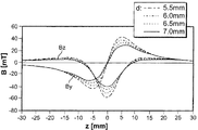
図3において、磁界成分By,Bzに対する線の群は、パラメータとして異なる間隔bで指示される。値に関して最も小さい磁界を有する線は、夫々、最大の間隔(この例では、7mm)を有する線である。その角度が永久磁石の位置への依存によってそれらの磁界成分から計算されると、図4に示される経路が得られる。勾配誤差が如何に大きいかを示すために、特性線が一方を他方から引き、且つパーセント誤差が設定される。図5に示される依存は、結果として生成される。 In FIG. 3, a group of lines for the magnetic field components By and Bz are indicated with different intervals b as parameters. The lines with the smallest magnetic field with respect to the value are each the lines with the largest spacing (7 mm in this example). When the angle is calculated from their magnetic field components by dependence on the position of the permanent magnet, the path shown in FIG. 4 is obtained. To show how large the slope error is, a characteristic line is drawn from one to the other and a percent error is set. The dependency shown in FIG. 5 is generated as a result.
線106は、7mmの間隔に対する線と6.5mmの間隔に対する線との間の誤差を示し、他方、線108は、6.5mmの間隔に対する角度αと5.5mmの間隔に対する角度との差を表す。即ち、1mmの間隔のバラツキは、1.6%の偏差となり、且つ1.5mmの間隔のバラツキは、2.3%の偏差となる。
しかしながら、これは、例えば、自動車における支援ステアリングシステムやペダル移動測定のような非常に感度の高いシステムには許容されない。この結果、永久磁石とホールセンサ要素との間の間隔の望ましくないバラツキに関してあまり感度が高くない改良された信号処理作業が必要である。 However, this is unacceptable for very sensitive systems such as assist steering systems and pedal movement measurements in automobiles, for example. As a result, there is a need for an improved signal processing operation that is not very sensitive with respect to undesirable variations in spacing between the permanent magnet and the Hall sensor element.
本発明の目的は、上述のタイプの測定方法と変位センサを提供して、可能な限り広い測定範囲にわたって直線的な測定信号を生成し、磁界源と磁界センサとの間の間隔におけるバラツキによる影響を可能な限り小さくすることである。 The object of the present invention is to provide a measurement method and a displacement sensor of the type described above to generate a linear measurement signal over the widest possible measurement range and to influence the variation in the spacing between the magnetic field source and the magnetic field sensor. Is as small as possible.
この目的は、独立の請求項の主題によって達成される。従属の請求項は、本発明に従う方法と変位センサの有利な展開に関連する。 This object is achieved by the subject matter of the independent claims. The dependent claims relate to advantageous developments of the method and the displacement sensor according to the invention.
本発明は、アークタンジェント計算において移動方向の磁界成分に対する値を直接に使用せず、代わりに、修正値によってこの項を拡張する概念に基づく。そのオフセット値は、異なる間隔dで角度αに対する線の勾配適応となる。 The present invention is based on the concept of not directly using the value for the magnetic field component in the moving direction in the arctangent calculation, but instead extending this term with a modified value. The offset value is a line slope adaptation with respect to the angle α at different intervals d.
これは、比較的に単純な計算作業であるので、極度に単純な方法で汎用型に従って変位センサの精度を向上することができる。 Since this is a relatively simple calculation task, the accuracy of the displacement sensor can be improved in accordance with the general-purpose type in an extremely simple manner.
本発明をより良く理解するために、以下の図面に示される実施形態を参照してより詳細に説明される。同一のコンポーネントは、同一の参照符号及び同一のコンポーネント記号表示で示される。 For a better understanding of the present invention, it will be described in more detail with reference to the embodiments shown in the following drawings. The same components are indicated with the same reference signs and the same component symbol designations.
更に、示され且つ記述される実施形態からの個々の特徴と特徴の組合せもまた本発明に従う独立の発明解決策(単数又は複数)を個別に構成し得る。 Moreover, individual features and combinations of features from the illustrated and described embodiments may also individually constitute independent invention solution (s) according to the present invention.
本発明は、最初に、図6と図1を参照して以下でより詳細に説明される。 The present invention will first be described in more detail below with reference to FIGS.
第1の実施形態に従う変位センサ配置が図1に示されている。ホールセンサ100は、所定位置に固定されるように取り付けられ、永久磁石102は、そのホールセンサ100に関連して線状に移動可能であるように支持される。永久磁石102は、そのN極/S極の軸線が移動方向と平行に配向されるような極構成を有する。しかしながら、原理上は、N極/S極の軸線が移動方向に対して横切るように延在する極構成を永久磁石102が有する配置に対して本発明の原理を使用することも可能である。永久磁石102は、例えば、図1に示されるゼロ位置から二つの方向へ、例えば約25mmだけ変位されることができる。ホールセンサ100は、少なくとも二つの直交磁界成分、即ち移動線に沿って延在する成分とそれに対して横方向へ延在する成分を検出する。それら二つの成分のベクトル加法は磁界の値|B|を提供する。角度αは、移動方向に対して垂直な線と全磁界ベクトル|B|とのなす角度として定義される。
A displacement sensor arrangement according to the first embodiment is shown in FIG. The
既に述べたように、角度αは、式(1)に従って移動方向における又はそれに対して横方向の磁界成分から計算される。

当然、本発明に従う原理を他の磁界源、例えば、電磁石、及び磁気抵抗センサや誘導センサのような磁界センサへ移すことも可能である。 Of course, it is also possible to transfer the principle according to the invention to other magnetic field sources such as electromagnets and magnetic field sensors such as magnetoresistive sensors and inductive sensors.
図6は、磁界センサ、この例では、ホールセンサ100である磁界センサの永久磁石102の位置に従って測定される測定信号を示す。これらの信号は、一方では移動方向における磁界の値Bzであり、他方では移動方向に対して横方向の磁界の値Byである。勿論、計算のために、Byに対して直交方向へ延在する値Bxを使用することも可能である。
FIG. 6 shows the measurement signal measured according to the position of the
本発明に従って、式(1)に従うByに対するBzの割合のアークタンジェントは、測定信号として使用されないが、代わりに、移動方向へ延在する磁界成分Bzがオフセット値によって修正される。そのオフセット値は、勾配適応(gradient adaptation)となる。以下の式(2)は、角度αの計算のために生成される。
修正された済(Bz+OS)線は図6では、参照番号110で示されている。 The modified finished (Bz + OS) line is indicated in FIG.
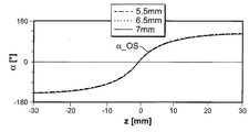
修正された角度α_OSの線進行方向は、異なる間隔dに対して図7で考察されると、その線の進行方向は、その線の群に対するパラメータとしてここで示される間隔dのバラツキに実質的にあまり依存しないことが明白である。 If the line travel direction of the modified angle α_OS is considered in FIG. 7 for different distances d, the travel direction of the lines is substantially equal to the variation of the distance d shown here as a parameter for the group of lines. It is clear that it is not very dependent on
このことは、一方では、組立誤差が本発明に従う解決策で受け入れられるが、他方では、バラツキに起因する影響も防止されることを意味する。 This means that, on the one hand, assembly errors are accepted in the solution according to the invention, but on the other hand the effects due to variations are also prevented.
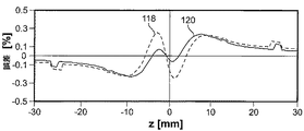
図8と図9の線は、各ケースにおけるより高い値との関連で、d=6.5mmに比較してのd=7mmに対する角度α_OSの対応する相対誤差(線118は、α_7.0mm−α_OS_6.5mmの相対誤差を指す)及びd=6.5mm及びd=5.5mmに対する角度α_OSの対応する相対誤差(線120は、α_OS_6.5mm−α_OS_5.5mmを指す)を示す。
The lines in FIGS. 8 and 9 are related to the higher value in each case, and the corresponding relative error of angle α_OS for d = 7 mm compared to d = 6.5 mm (
図5の線に比較して、測定信号への間隔dの影響は、この例では実質的により小さい。1mmの間隔のばらつきは0.3%未満の偏差となり、1.5mmの間隔のばらつきも0.3%未満の偏差となる。 Compared to the line in FIG. 5, the influence of the spacing d on the measurement signal is substantially smaller in this example. The 1 mm interval variation is less than 0.3% deviation, and the 1.5 mm interval variation is also less than 0.3% deviation.
本発明に従って、出力信号の間隔依存は、未修正計算に対して約1/8へ減少される。 In accordance with the present invention, the interval dependence of the output signal is reduced to approximately 1/8 for uncorrected calculations.
図6で使用される修正値は、OS=14.7mTである。その値の計算による設定は、図10と図11を参照して以下でより詳細に説明される。 The correction value used in FIG. 6 is OS = 14.7 mT. The setting by calculation of the value is described in more detail below with reference to FIGS.
図10において、直交磁界成分By,Bzの経路が示される。図11は、永久磁石102の位置に従う線Bzと、位置xに対する移動に沿う磁界成分の導関数とを示している。項OSに対する最適条件は、Bzの変曲点がゼロに等しい時に、即ち、二次導関数がゼロすなわち図示の線112の勾配が水平である時に達成されることが理解される。
In FIG. 10, paths of orthogonal magnetic field components By and Bz are shown. FIG. 11 shows the line Bz according to the position of the
Bzの最大値とd2Bz/dz2=0の位置での値との間の差が図1に示される実施形態に対してOS=14.7mTのオフセット値となる。 The difference between the maximum value of Bz and the value at the position of d2Bz / dz2 = 0 is an offset value of OS = 14.7 mT for the embodiment shown in FIG.
しかしながら、そのオフセット値は、必ずしも計算方法において磁界成分へ追加される必要はないが、代わりに、定数因数が常に本発明に従う方法へ追加されるので、このオフセット値は他の補助磁石114によって物理的に生成されてもよい。
However, the offset value does not necessarily have to be added to the magnetic field component in the calculation method, but instead, this offset value is physically added by other
補助磁石114は、移動可能永久磁石からの間隔がホールセンサ100と同じ間隔dである平面に配置されることができる(図12と図13を参照)。補助磁石114のおかげで、式(2)に従う必要な修正を保証する磁界成分が移動方向Bz_OSに生成される。
The
しかしながら、或いは、補助磁石114は、回路キャリア、例えば、印刷回路基板(PCB)116の後部側に、即ちホールセンサ100が構成されるPCB116の他方の側に、取り付けられてもよい。この実施形態が概略的に図14に示される。
Alternatively, however, the
補助磁石114を使用するハードウェア解決策は、計算準備が式(1)に従って非変更状態で実行されることができるが、それにもかかわらず向上されたレベルの精度が達成される利点を有する。
The hardware solution using the
本発明に従う解決策の利点は、図15と図16の比較によって直接的に示されることができる。 The advantages of the solution according to the invention can be shown directly by comparing FIG. 15 and FIG.
図15は、パラメータとして磁石とセンサとの間の異なる距離dに対する永久磁石の変位に従うセンサの出力信号を示している。間隔におけるバラツキに従う異なる勾配値が明瞭に見られる。しかしながら、対応する磁界成分の最大値と変曲点の値との間の差の値が図11を参照して上記のように計算されると、14.7mTのオフセット値が得られる。値14.7mTによって修正された値がアークタンジェント計算のために非修正磁界成分の代わりに使用されると、図16の線の群が、一般的には間隔に大きく依存している図15の特性線の群に比較して生成される。 FIG. 15 shows the output signal of the sensor according to the displacement of the permanent magnet for different distances d between the magnet and the sensor as parameters. The different slope values according to the variation in the spacing are clearly seen. However, if the value of the difference between the corresponding maximum value of the magnetic field component and the value of the inflection point is calculated as described above with reference to FIG. 11, an offset value of 14.7 mT is obtained. When the value modified by the value 14.7 mT is used instead of the unmodified magnetic field component for arctangent calculations, the group of lines in FIG. 16 is generally highly dependent on the spacing of FIG. Generated compared to a group of characteristic lines.
間隔dのバラツキの場合、永久磁石とホールセンサとの間の間隔dに従う特性線の偏差が図16ではもう全く設定されず、勾配値が測定ノイズに関して最早検出されない。 In the case of the variation of the distance d, the deviation of the characteristic line according to the distance d between the permanent magnet and the Hall sensor is no longer set in FIG. 16, and the gradient value is no longer detected with respect to the measurement noise.
100 ホールセンサ
102 永久磁石
104 線進行方向α_lin
106 線進行方向α_7.0mm−α_6.5mm
108 線進行方向α_6.5mm−α_5.5mm
110 線進行方向Bz+OS
112 線進行方向α_OS
114 補助磁石
116 回路キャリア(PCB)
118 線進行方向α_OS_7.0mm−α_OS_6.5mm
120 線進行方向α_OS_6.5mm−α_OS_5.5mm
100
106 Line traveling direction α_7.0 mm-α_6.5 mm
108 Line direction α_6.5mm-α_5.5mm
110 Line direction Bz + OS
112 Line traveling direction α_OS
114
118 line traveling direction α_OS_7.0 mm-α_OS_6.5 mm
120 line traveling direction α_OS_6.5 mm-α_OS_5.5 mm
Claims (6)
前記磁界源と前記磁界センサが互いに対して移動可能であり、
前記磁界センサが前記磁界の少なくとも二つの磁界成分を測定し、前記測定された成分から位置信号が生成され、
前記方法が、
前記二つの磁界成分の割合に基づいて前記位置信号を計算する工程と、
前記割合が計算される前に、前記磁界源と前記磁界センサとの間に相対移動方向へ延在する前記磁気成分を修正する工程と
を備え、
前記修正工程における必要な修正の値は、
位置の値に従って前記移動方向における磁界成分の線を設定する工程と、
前記位置の値に従って前記線の二次導関数を計算し且つ前記二次導関数のゼロ位置を設定する工程と、
前記修正のためのオフセット値を計算するために前記ゼロ位置の前記線の関数値を最小間隔の位置の関数値にから減算する工程と
によって設定されることを特徴とする方法。 A method for non-contact measurement of a relative position of a magnetic field source and a magnetic field sensor that generate a magnetic field with respect to each other,
The magnetic field source and the magnetic field sensor are movable relative to each other;
Wherein the magnetic field sensor measures at least two magnetic field components of the magnetic field, the position signal from the previous SL measured component is generated,
The method comprises
Calculating the position signal based on a ratio of the two magnetic field components;
Modifying the magnetic component extending in the direction of relative movement between the magnetic field source and the magnetic field sensor before the ratio is calculated;
The required correction value in the correction process is:
Setting a line of the magnetic field component in the moving direction according to the value of the position;
Calculating a second derivative of the line according to the position value and setting a zero position of the second derivative;
Subtracting the function value of the line at the zero position from the function value of the minimum spacing position to calculate the offset value for the correction.
前記方法は、
前記相対移動方向へ延在する磁気成分に対する少なくとも第1の測定値を設定する工程と、
前記相対移動方向に対して横方向に延在する磁界成分に対する少なくとも第2の測定値を設定する工程と、
修正項によって修正された前記第1の測定値と前記第2の測定値の割合から前記位置信号を計算する工程と
を備えることを特徴とする請求項1に記載の方法。 A relative linear movement is performed between the magnetic field source and the magnetic field sensor;
The method
Setting at least a first measurement value for a magnetic component extending in the relative movement direction;
Setting at least a second measurement value for a magnetic field component extending transversely to the relative movement direction;
The method of claim 1, comprising calculating the position signal from a ratio of the first measurement value and the second measurement value corrected by a correction term.
Applications Claiming Priority (3)
| Application Number | Priority Date | Filing Date | Title |
|---|---|---|---|
| DE102011115302A DE102011115302A1 (en) | 2011-09-29 | 2011-09-29 | Method for the contactless measurement of a relative position by means of a Hall sensor |
| DE102011115302.4 | 2011-09-29 | ||
| PCT/EP2012/068842 WO2013045430A1 (en) | 2011-09-29 | 2012-09-25 | Method for contactless measurement of a relative position by means of a hall sensor |
Publications (3)
| Publication Number | Publication Date |
|---|---|
| JP2014528085A JP2014528085A (en) | 2014-10-23 |
| JP2014528085A5 JP2014528085A5 (en) | 2017-06-15 |
| JP6210642B2 true JP6210642B2 (en) | 2017-10-11 |
Family
ID=46982547
Family Applications (1)
| Application Number | Title | Priority Date | Filing Date |
|---|---|---|---|
| JP2014532346A Active JP6210642B2 (en) | 2011-09-29 | 2012-09-25 | Method for non-contact measurement of relative position with Hall sensors |
Country Status (7)
| Country | Link |
|---|---|
| US (1) | US9360537B2 (en) |
| EP (1) | EP2761254B1 (en) |
| JP (1) | JP6210642B2 (en) |
| CN (1) | CN103988052B (en) |
| BR (1) | BR112014007387A2 (en) |
| DE (1) | DE102011115302A1 (en) |
| WO (1) | WO2013045430A1 (en) |
Families Citing this family (24)
| Publication number | Priority date | Publication date | Assignee | Title |
|---|---|---|---|---|
| EP2997390B1 (en) | 2013-05-24 | 2017-09-06 | Allegro Microsystems, LLC | Magnetic field sensor for detecting a magnetic field in any direction above thresholds |
| US9733106B2 (en) | 2013-05-24 | 2017-08-15 | Allegro Microsystems, Llc | Magnetic field sensor to detect a magnitude of a magnetic field in any direction |
| DE102013222097B4 (en) * | 2013-10-30 | 2023-03-02 | Te Connectivity Germany Gmbh | Temperature compensation method for control magnetic fields in a Hall sensor with OS adaptation |
| US10534044B2 (en) | 2013-10-30 | 2020-01-14 | Te Connectivity Germany Gmbh | Temperature compensation method of magnetic control fields in a hall sensor with OS adaption |
| WO2015144160A1 (en) | 2014-03-26 | 2015-10-01 | Schaeffler Technologies AG & Co. KG | Sensor-magnet assembly |
| US11226211B2 (en) | 2014-09-08 | 2022-01-18 | Texas Instruments Incorporated | Inductive position detection |
| KR102629037B1 (en) * | 2015-08-19 | 2024-01-25 | 알레그로 마이크로시스템스, 엘엘씨 | Magnetic field sensor that detects the size of the magnetic field with random detection |
| CN106524887B (en) * | 2015-09-14 | 2019-04-19 | 上海汽车集团股份有限公司 | The method and device of Hall sensor measurement displacement |
| US9835472B2 (en) * | 2015-09-25 | 2017-12-05 | Infineon Technologies Ag | Using cartesian coordinates for position detection with a magnetic sensor |
| JP2017067480A (en) * | 2015-09-28 | 2017-04-06 | メレキシス テクノロジーズ エヌ ヴィ | Displacement detector and stepless gearbox |
| DE102016110968B4 (en) * | 2016-06-15 | 2019-05-02 | Sick Ag | sensor |
| CN106181435A (en) * | 2016-08-26 | 2016-12-07 | 景德镇翼腾科技有限公司 | Electric turntable and control method thereof |
| EP3428582B1 (en) * | 2017-07-11 | 2020-03-04 | Sick Ag | Sensor |
| US10509082B2 (en) * | 2018-02-08 | 2019-12-17 | Nxp B.V. | Magnetoresistive sensor systems with stray field cancellation utilizing auxiliary sensor signals |
| CN109029228B (en) * | 2018-05-30 | 2021-01-05 | 中南大学 | System and method for measuring relative offset between rail vehicle and steel rail |
| EP4056956A1 (en) * | 2018-06-26 | 2022-09-14 | Melexis Technologies SA | Position sensor system and method, robust against disturbance fields |
| AT521356B1 (en) * | 2018-07-18 | 2020-01-15 | Avl List Gmbh | Differential pressure transducer for a flow meter and flow meter |
| JP6992771B2 (en) * | 2019-01-29 | 2022-01-13 | Tdk株式会社 | Magnetic unit, position detector and magnetic member |
| EP3705902B1 (en) * | 2019-03-08 | 2021-10-27 | EM Microelectronic-Marin SA | Method of determining an absolute angle of a magnetic field |
| US11467225B2 (en) | 2019-03-08 | 2022-10-11 | Em Microelectronic-Marin Sa | Method of determining an absolute angle of a magnetic field |
| DE102019205679B4 (en) | 2019-04-18 | 2022-12-15 | Infineon Technologies Ag | Linearization of input signals |
| DE102019112572A1 (en) * | 2019-05-14 | 2020-11-19 | HELLA GmbH & Co. KGaA | Device and method for the contactless determination of a position of a pedal |
| CN111322991B (en) * | 2020-04-16 | 2021-07-20 | 赤峰华源新力科技有限公司 | System for measuring wind power tower cylinder inclination angle based on three-dimensional Hall sensor |
| CN113776416B (en) * | 2021-08-27 | 2024-02-06 | 浙江沃德尔科技集团股份有限公司 | Detection device for non-contact pedal position resisting magnetic field interference |
Family Cites Families (26)
| Publication number | Priority date | Publication date | Assignee | Title |
|---|---|---|---|---|
| JPS5418768A (en) * | 1977-07-12 | 1979-02-13 | Mitsubishi Electric Corp | Angle sensor |
| EP0115391A3 (en) * | 1983-01-27 | 1987-06-10 | Optron, Inc. | Hall-effect position sensor apparatus |
| US4737710A (en) * | 1983-01-27 | 1988-04-12 | Trw Inc. | Hall-effect array for sensing second spatial derivative of magnetic field |
| DE19543564A1 (en) * | 1994-11-22 | 1996-05-23 | Bosch Gmbh Robert | Non-contact rotary angle determn. appts for rotating element |
| DE19836599A1 (en) | 1998-08-13 | 2000-02-17 | Windhorst Beteiligungsgesellsc | Process for the contactless magnetic detection of linear relative movements between permanent magnets and electronic sensors |
| JP2001296142A (en) * | 2000-04-14 | 2001-10-26 | Yaskawa Electric Corp | Rotating position detector and rotating speed detector |
| EP1243897B1 (en) | 2001-03-23 | 2013-12-18 | Melexis Technologies NV | Magnetic position sensor |
| JP2002372402A (en) * | 2001-06-13 | 2002-12-26 | Alps Electric Co Ltd | Seat position sensor |
| JP2003075108A (en) * | 2001-09-04 | 2003-03-12 | Asahi Kasei Corp | Rotation angle sensor |
| JP2003167627A (en) * | 2001-12-04 | 2003-06-13 | Sanetec:Kk | Position detecting sensor |
| JP2003240598A (en) * | 2002-02-13 | 2003-08-27 | Asahi Kasei Corp | Digital angle measuring system |
| DE102004002649A1 (en) * | 2004-01-17 | 2005-08-11 | Ssg Semiconductor Systems Gmbh | Position tolerant distance and angle sensor for hydraulic actuators has two active sensor elements with signal difference compared to maximum or null difference |
| US7112962B2 (en) * | 2004-11-18 | 2006-09-26 | Honeywell International Inc. | Angular position detection utilizing a plurality of rotary configured magnetic sensors |
| CN101124465A (en) * | 2005-02-01 | 2008-02-13 | Ncte工程有限公司 | Position sensor and washing machine |
| JP5027821B2 (en) * | 2006-02-03 | 2012-09-19 | ムーグ インコーポレーテッド | Encoder signal analysis system for high resolution position measurement |
| JP4756475B2 (en) * | 2006-10-20 | 2011-08-24 | 株式会社デンソー | Magnetic rotor and rotation angle detection device |
| FR2909170B1 (en) * | 2006-11-28 | 2010-01-29 | Moving Magnet Tech Mmt | LINER OR ROTARY POSITION SENSOR WITH VARIABLE MAGNETIC PROFILE PREFERENTIALLY AS WELL AS SINUSOIDAL. |
| DE102006061927A1 (en) * | 2006-12-21 | 2008-06-26 | Siemens Ag | Method and device for measuring the pole angle of a magnetic levitation vehicle of a magnetic levitation railway |
| JP2009002737A (en) * | 2007-06-20 | 2009-01-08 | Denso Corp | Rotation angle detector |
| DE102007060707B4 (en) * | 2007-12-17 | 2017-12-07 | Austriamicrosystems Ag | Arrangement for detecting a movement of a body and method for operating such an arrangement |
| CN101216324B (en) * | 2008-01-18 | 2011-07-06 | 浙江飞亚电子有限公司 | Angular displacement sensor |
| JP4900837B2 (en) * | 2008-05-16 | 2012-03-21 | 日立金属株式会社 | Rotation angle detector and rotating machine |
| DE102008045177A1 (en) | 2008-08-30 | 2010-03-04 | Festo Ag & Co. Kg | Measuring method for the contactless detection of linear relative movements between a sensor arrangement and a permanent magnet |
| JP5216030B2 (en) * | 2010-01-28 | 2013-06-19 | 東京コスモス電機株式会社 | Multi-directional input device |
| DE102010011723B4 (en) * | 2010-03-17 | 2012-06-06 | Austriamicrosystems Ag | Sensor arrangement and method for operating a sensor arrangement |
| DE102012205903B4 (en) * | 2012-04-11 | 2014-01-30 | Tyco Electronics Amp Gmbh | METHOD FOR CONTACTLESSLY MEASURING A RELATIVE POSITION BY MEANS OF A MAGNETIC FIELD SENSOR ARRAY TO HALLE EFFECT BASE AND TRANSMITTER |
-
2011
- 2011-09-29 DE DE102011115302A patent/DE102011115302A1/en not_active Ceased
-
2012
- 2012-09-25 JP JP2014532346A patent/JP6210642B2/en active Active
- 2012-09-25 WO PCT/EP2012/068842 patent/WO2013045430A1/en active Application Filing
- 2012-09-25 US US14/348,029 patent/US9360537B2/en active Active
- 2012-09-25 CN CN201280047390.7A patent/CN103988052B/en active Active
- 2012-09-25 BR BR112014007387A patent/BR112014007387A2/en active Search and Examination
- 2012-09-25 EP EP12769364.6A patent/EP2761254B1/en active Active
Also Published As
| Publication number | Publication date |
|---|---|
| CN103988052B (en) | 2017-03-01 |
| CN103988052A (en) | 2014-08-13 |
| DE102011115302A1 (en) | 2013-04-04 |
| EP2761254B1 (en) | 2015-09-16 |
| BR112014007387A2 (en) | 2017-04-04 |
| EP2761254A1 (en) | 2014-08-06 |
| US20140239942A1 (en) | 2014-08-28 |
| JP2014528085A (en) | 2014-10-23 |
| US9360537B2 (en) | 2016-06-07 |
| WO2013045430A1 (en) | 2013-04-04 |
Similar Documents
| Publication | Publication Date | Title |
|---|---|---|
| JP6210642B2 (en) | Method for non-contact measurement of relative position with Hall sensors | |
| JP6113197B2 (en) | Method for non-contact measurement of relative position by a three-dimensional Hall sensor having a measurement signal storage unit | |
| EP3469383B1 (en) | Magnetic field sensor having error correction | |
| JP6491204B2 (en) | Temperature compensation method of magnetic control field in hall sensor for OS adaptation | |
| JP5834292B2 (en) | Current sensor | |
| US9335149B2 (en) | Displacement sensor for contactlessly measuring a position by means of a plurality of magnetic field sensors arranged in series | |
| US9982988B2 (en) | Displacement sensor for contactlessly measuring a relative position by means of a magnetic field sensor array on the basis of the hall effect | |
| US10732009B2 (en) | Angle sensing in an off-axis configuration | |
| US10670425B2 (en) | System for measuring angular position and method of stray field cancellation | |
| US10816363B2 (en) | Angular sensor system and method of stray field cancellation | |
| CN105222812A (en) | There is the sensing system of three half-bridge structures | |
| US10534044B2 (en) | Temperature compensation method of magnetic control fields in a hall sensor with OS adaption | |
| CN114391090A (en) | Displacement measuring device with Hall sensor and magnet | |
| US20170059363A1 (en) | Magnetoresistive angle sensor with linear sensor elements | |
| KR102032463B1 (en) | Apparatus for measuring steering angle of vehicle | |
| JP2011180009A (en) | Position sensor and position detection method |
Legal Events
| Date | Code | Title | Description |
|---|---|---|---|
| A521 | Request for written amendment filed |
Free format text: JAPANESE INTERMEDIATE CODE: A523 Effective date: 20150706 |
|
| A621 | Written request for application examination |
Free format text: JAPANESE INTERMEDIATE CODE: A621 Effective date: 20150706 |
|
| A977 | Report on retrieval |
Free format text: JAPANESE INTERMEDIATE CODE: A971007 Effective date: 20160602 |
|
| A131 | Notification of reasons for refusal |
Free format text: JAPANESE INTERMEDIATE CODE: A131 Effective date: 20160614 |
|
| A521 | Request for written amendment filed |
Free format text: JAPANESE INTERMEDIATE CODE: A523 Effective date: 20160907 |
|
| A131 | Notification of reasons for refusal |
Free format text: JAPANESE INTERMEDIATE CODE: A131 Effective date: 20170206 |
|
| A524 | Written submission of copy of amendment under article 19 pct |
Free format text: JAPANESE INTERMEDIATE CODE: A524 Effective date: 20170501 |
|
| TRDD | Decision of grant or rejection written | ||
| A01 | Written decision to grant a patent or to grant a registration (utility model) |
Free format text: JAPANESE INTERMEDIATE CODE: A01 Effective date: 20170911 |
|
| A61 | First payment of annual fees (during grant procedure) |
Free format text: JAPANESE INTERMEDIATE CODE: A61 Effective date: 20170911 |
|
| R150 | Certificate of patent or registration of utility model |
Ref document number: 6210642 Country of ref document: JP Free format text: JAPANESE INTERMEDIATE CODE: R150 |
|
| R250 | Receipt of annual fees |
Free format text: JAPANESE INTERMEDIATE CODE: R250 |
|
| R250 | Receipt of annual fees |
Free format text: JAPANESE INTERMEDIATE CODE: R250 |
|
| R250 | Receipt of annual fees |
Free format text: JAPANESE INTERMEDIATE CODE: R250 |
|
| R250 | Receipt of annual fees |
Free format text: JAPANESE INTERMEDIATE CODE: R250 |