EP4174337B1 - Kupplungseinrichtung für einen fahrzeuglüfter - Google Patents
Kupplungseinrichtung für einen fahrzeuglüfter Download PDFInfo
- Publication number
- EP4174337B1 EP4174337B1 EP22199849.5A EP22199849A EP4174337B1 EP 4174337 B1 EP4174337 B1 EP 4174337B1 EP 22199849 A EP22199849 A EP 22199849A EP 4174337 B1 EP4174337 B1 EP 4174337B1
- Authority
- EP
- European Patent Office
- Prior art keywords
- output
- drive
- locking claws
- clutch
- coupling
- Prior art date
- Legal status (The legal status is an assumption and is not a legal conclusion. Google has not performed a legal analysis and makes no representation as to the accuracy of the status listed.)
- Active
Links
Images


Classifications
-
- F—MECHANICAL ENGINEERING; LIGHTING; HEATING; WEAPONS; BLASTING
- F16—ENGINEERING ELEMENTS AND UNITS; GENERAL MEASURES FOR PRODUCING AND MAINTAINING EFFECTIVE FUNCTIONING OF MACHINES OR INSTALLATIONS; THERMAL INSULATION IN GENERAL
- F16D—COUPLINGS FOR TRANSMITTING ROTATION; CLUTCHES; BRAKES
- F16D41/00—Freewheels or freewheel clutches
- F16D41/12—Freewheels or freewheel clutches with hinged pawl co-operating with teeth, cogs, or the like
-
- F—MECHANICAL ENGINEERING; LIGHTING; HEATING; WEAPONS; BLASTING
- F01—MACHINES OR ENGINES IN GENERAL; ENGINE PLANTS IN GENERAL; STEAM ENGINES
- F01P—COOLING OF MACHINES OR ENGINES IN GENERAL; COOLING OF INTERNAL-COMBUSTION ENGINES
- F01P7/00—Controlling of coolant flow
- F01P7/02—Controlling of coolant flow the coolant being cooling-air
- F01P7/08—Controlling of coolant flow the coolant being cooling-air by cutting in or out of pumps
- F01P7/081—Controlling of coolant flow the coolant being cooling-air by cutting in or out of pumps using clutches, e.g. electro-magnetic or induction clutches
- F01P7/082—Controlling of coolant flow the coolant being cooling-air by cutting in or out of pumps using clutches, e.g. electro-magnetic or induction clutches using friction clutches
- F01P7/087—Controlling of coolant flow the coolant being cooling-air by cutting in or out of pumps using clutches, e.g. electro-magnetic or induction clutches using friction clutches actuated directly by deformation of a thermostatic device
-
- F—MECHANICAL ENGINEERING; LIGHTING; HEATING; WEAPONS; BLASTING
- F01—MACHINES OR ENGINES IN GENERAL; ENGINE PLANTS IN GENERAL; STEAM ENGINES
- F01P—COOLING OF MACHINES OR ENGINES IN GENERAL; COOLING OF INTERNAL-COMBUSTION ENGINES
- F01P5/00—Pumping cooling-air or liquid coolants
- F01P5/02—Pumping cooling-air; Arrangements of cooling-air pumps, e.g. fans or blowers
- F01P5/04—Pump-driving arrangements
-
- F—MECHANICAL ENGINEERING; LIGHTING; HEATING; WEAPONS; BLASTING
- F16—ENGINEERING ELEMENTS AND UNITS; GENERAL MEASURES FOR PRODUCING AND MAINTAINING EFFECTIVE FUNCTIONING OF MACHINES OR INSTALLATIONS; THERMAL INSULATION IN GENERAL
- F16D—COUPLINGS FOR TRANSMITTING ROTATION; CLUTCHES; BRAKES
- F16D41/00—Freewheels or freewheel clutches
- F16D41/04—Freewheels or freewheel clutches combined with a clutch for locking the driving and driven members
-
- F—MECHANICAL ENGINEERING; LIGHTING; HEATING; WEAPONS; BLASTING
- F16—ENGINEERING ELEMENTS AND UNITS; GENERAL MEASURES FOR PRODUCING AND MAINTAINING EFFECTIVE FUNCTIONING OF MACHINES OR INSTALLATIONS; THERMAL INSULATION IN GENERAL
- F16D—COUPLINGS FOR TRANSMITTING ROTATION; CLUTCHES; BRAKES
- F16D43/00—Automatic clutches
- F16D43/02—Automatic clutches actuated entirely mechanically
- F16D43/25—Automatic clutches actuated entirely mechanically controlled by thermo-responsive elements
-
- F—MECHANICAL ENGINEERING; LIGHTING; HEATING; WEAPONS; BLASTING
- F01—MACHINES OR ENGINES IN GENERAL; ENGINE PLANTS IN GENERAL; STEAM ENGINES
- F01P—COOLING OF MACHINES OR ENGINES IN GENERAL; COOLING OF INTERNAL-COMBUSTION ENGINES
- F01P11/00—Component parts, details, or accessories not provided for in, or of interest apart from, groups F01P1/00 - F01P9/00
- F01P11/14—Indicating devices; Other safety devices
-
- F—MECHANICAL ENGINEERING; LIGHTING; HEATING; WEAPONS; BLASTING
- F01—MACHINES OR ENGINES IN GENERAL; ENGINE PLANTS IN GENERAL; STEAM ENGINES
- F01P—COOLING OF MACHINES OR ENGINES IN GENERAL; COOLING OF INTERNAL-COMBUSTION ENGINES
- F01P2031/00—Fail safe
- F01P2031/30—Cooling after the engine is stopped
-
- F—MECHANICAL ENGINEERING; LIGHTING; HEATING; WEAPONS; BLASTING
- F01—MACHINES OR ENGINES IN GENERAL; ENGINE PLANTS IN GENERAL; STEAM ENGINES
- F01P—COOLING OF MACHINES OR ENGINES IN GENERAL; COOLING OF INTERNAL-COMBUSTION ENGINES
- F01P7/00—Controlling of coolant flow
- F01P7/02—Controlling of coolant flow the coolant being cooling-air
- F01P7/08—Controlling of coolant flow the coolant being cooling-air by cutting in or out of pumps
- F01P7/081—Controlling of coolant flow the coolant being cooling-air by cutting in or out of pumps using clutches, e.g. electro-magnetic or induction clutches
- F01P7/082—Controlling of coolant flow the coolant being cooling-air by cutting in or out of pumps using clutches, e.g. electro-magnetic or induction clutches using friction clutches
- F01P7/088—Controlling of coolant flow the coolant being cooling-air by cutting in or out of pumps using clutches, e.g. electro-magnetic or induction clutches using friction clutches actuated in response to driving speed, e.g. by centrifugal devices
Definitions
- the invention relates to a vehicle fan for an agricultural vehicle, with a coupling device.
- Such a coupling device for a vehicle fan is known, for example, in the form of a so-called viscous coupling, in which a valve is opened by means of a bimetallic element as the temperature of a vehicle unit to be cooled increases in order to pump pressurized hydraulic fluid into a working chamber of the viscous coupling in order to increase the coupling closure.
- a valve is opened by means of a bimetallic element as the temperature of a vehicle unit to be cooled increases in order to pump pressurized hydraulic fluid into a working chamber of the viscous coupling in order to increase the coupling closure.
- a rigid coupling is usually used between a pulley of a belt drive driven by the combustion engine and a fan wheel, which is used to generate a cooling air flow that acts on an engine heat exchanger. If the combustion engine is switched off, the belt drive comes to a standstill relatively quickly. However, due to its inertia, the fan wheel tends to continue to rotate for a certain period of time. This leads to the connected pulley spinning along the stationary drive belt, causing undesirable wear and noticeable vibrations or noises.
- the vehicle fan according to the invention for an agricultural vehicle, with a coupling device comprises, in addition to a drive-side coupling element, an output-side coupling element, wherein a locking mechanism is designed between the two coupling elements in such a way that a rotary connection established between the coupling elements is released when a drive-side speed drops compared to an output-side speed.
- the freewheel formed in this way can only transmit torque in one direction of rotation. If the two coupling elements rotate in opposite directions to each other, or if the output-side speed is greater than the input-side speed, the rotary joint is automatically released. In this way, it can be ensured that a fan blade driven by the coupling device can continue to rotate without reaction even if the input-side coupling element slows down or comes to a standstill.
- the drive-side coupling element has a hub that can be connected to a drive shaft, with a plurality of radially pivotable locking claws being mounted along an outer circumference of the hub, each of which is pre-tensioned into a deflected locking position by means of a spring element to produce the rotary connection.
- the hub has in particular an internal thread into which the drive shaft of a belt drive that can be driven by an internal combustion engine and is connected to a pulley can be screwed.
- a plurality of coupling ramps are formed along an inner circumference of the output-side coupling element for engaging a respective one of the locking claws.
- the locking claws can rest with a front end on a ramp end running essentially transversely to the direction of rotation.
- the locking claws can be pushed radially inwards from the deflected locking position along an inner contour of the coupling ramps against the preload generated by the respective spring element.
- the locking claws can have a curved course such that they each engage in a shoulder area on the inner contour of the Due to the enlargement of the contact surface created in this way, friction-related wear of locking claws and clutch ramps can be significantly reduced in freewheel operation. Both parts are typically made of surface-hardened steel.
- the number of coupling ramps corresponds to that of the locking claws or is a multiple of it.
- a total of 4 to 5 locking claws or coupling ramps are evenly distributed along the outer circumference of the hub or the inner circumference of the output-side coupling element. The exact number of locking claws ultimately depends on the torque to be transmitted by means of the coupling device.
- a mounting flange for mounting a fan wheel can be formed on the output-side coupling element.
- the fan wheel which is usually made of fiber-reinforced plastic, comprises a large number of fan blades that serve to generate an axial or radial cooling air flow.
- the fan wheel can be screwed to a hole ring provided on the mounting flange using a mounting hub.
- the drive-side coupling element is rotatably received within the output-side coupling element, in particular by means of a deep groove ball bearing.
- the deep groove ball bearing usually comprises an inner and an outer race.
- the outer race can be inserted into a receiving opening formed on the output-side coupling element and can be secured therein by means of a locking ring which engages in an inner groove running around the receiving opening.
- the inner race on the other hand, can be placed on a mounting projection on the hub and rest against a circumferential collar.
- Fig.1 shows in an exploded view the components of an embodiment of the vehicle fan according to the invention with a coupling device.
- the coupling device 10 comprises a drive-side coupling element 14 and an output-side coupling element 16 along a common axis of rotation 12.
- the drive-side coupling element 14 has a hub 18 (see also Fig.4 ). Along an outer circumference 20 of the hub 18, a plurality of radially pivotable locking claws 22 are mounted, each of which is pivoted by means of a spring element 24 into a Fig.2 reproduced deflected locking position are preloaded so that a rotary connection can be established between the two coupling elements 14, 16.
- a plurality of coupling ramps 28 are formed along an inner circumference 26 of the output-side coupling element 16 for engaging a respective one of the locking claws 22.
- the locking claws 22 rest with a front end 30 on a ramp end 32 which runs essentially transversely to the direction of rotation.
- the locking claws 22 can be pushed radially inwards from the deflected locking position to release the rotary connection along an inner contour 34 of the coupling ramps 28 against the preload generated by the respective spring element 24, wherein they are at least partially received by a respective recess 36 along the outer circumference 20 of the hub 18.
- This is the case, for example, when the two coupling elements 14, 16 rotate in opposite directions to one another or when the output-side speed is greater than the input-side speed.
- a freewheeling operation is in Fig.3 shown.
- the coupling device 10 more precisely the locking mechanism formed by the locking claws 22 or the coupling ramps 28, transmits a torque only in the predetermined direction of rotation.
- the number of coupling ramps 28 corresponds to that of the locking claws 22. Alternatively, however, it can also be a multiple of this. For example, a total of 4 locking claws 22 or coupling ramps 28 are evenly distributed along the outer circumference 20 of the hub 18 or the inner circumference 26 of the output-side coupling element 16.
- the locking claws 22 have a tangentially curved course with respect to the outer circumference 20 of the hub 18 such that they each rest in a shoulder area 38 on the inner contour 34 of the coupling ramps 28. Due to the enlargement of the contact surface created in this way, friction-related wear of the locking claws 22 and coupling ramps 28 can be significantly reduced in freewheel operation. Both parts are made of surface-hardened steel.
- Fig.4 also shows a sectional view of the coupling device 10 in the state installed on the vehicle fan 40 according to the invention. As can be seen by comparison with Fig.1 As can be seen, the drive-side coupling element 14 is rotatably received within the output-side coupling element 16 by means of a deep groove ball bearing 42.
- the deep groove ball bearing 42 comprises an inner race 44 and an outer race 46.
- the outer race 46 is inserted into a receiving opening formed on the output-side coupling element 16 48 and is secured therein essentially free of play by means of a locking ring 50 which engages in an inner groove 52 running around the receiving opening 48.
- the inner race 44 on the other hand, is placed on a fastening projection 54 formed on the hub 18 and rests there against a circumferential collar 56.
- a mounting flange 62 is provided for mounting a Fig.4 shown fan wheel 64.
- the fan wheel 64 which is made of fiber-reinforced plastic, comprises a plurality of fan blades 66, which serve to generate an axial cooling air flow 68.
- the fan wheel 64 is screwed to a hole ring 72 provided on the fastening flange 62 by means of a fastening hub 70.
- the hub 18 encompassed by the drive-side coupling element 14 has an internal thread 74 into which a drive shaft 78 connected to a pulley 76 is screwed, so that the hub 18 and drive shaft 78 are connected to one another in rotation.
- the pulley 76 is part of a belt drive 82 that can be driven by an internal combustion engine 80 and is located in the engine compartment 84 of an agricultural vehicle (not shown), for example an agricultural tractor.
Landscapes
- Engineering & Computer Science (AREA)
- General Engineering & Computer Science (AREA)
- Mechanical Engineering (AREA)
- Chemical & Material Sciences (AREA)
- Combustion & Propulsion (AREA)
- Mechanical Operated Clutches (AREA)
- Structures Of Non-Positive Displacement Pumps (AREA)
Description
- Die Erfindung betrifft einen Fahrzeuglüfter für ein landwirtschaftliches Fahrzeug, mit einer Kupplungseinrichtung.
- Eine derartige Kupplungseinrichtung für einen Fahrzeuglüfter ist beispielsweise in Form einer sogenannten Visco-Kupplung bekannt, bei der mit steigender Temperatur eines zu kühlenden Fahrzeugaggregats mittels eines Bimetallelements ein Ventil geöffnet wird, um zur Erhöhung des Kupplungsschlusses unter Druck stehende Hydraulikflüssigkeit in einen Arbeitsraum der Visco-Kupplung zu fördern. In der Folge steigt die Drehzahl eines über die Visco-Kupplung angetriebenen Lüfterrads und damit dessen Kühlleistung.
- Ein Beispiel für diese Art von Kupplungssystemen findet sich in der
US 9 121 461 B1 US 2008/093189 A1 zu sehen. - Bei einfacheren Anwendungen ist die Verwendung einer Visco-Kupplung jedoch zu kostspielig und daher unüblich. Dies gilt insbesondere für den Fall der Kühlung von Verbrennungsmotoren in landwirtschaftlichen Traktoren vergleichsweise geringer Leistungsklassen. Hier erfolgt üblicherweise eine starre Kopplung zwischen einer Riemenscheibe eines von dem Verbrennungsmotor angetriebenen Riementriebs und einem Lüfterrad, das der Erzeugung eines einen Motorwärmetauscher beaufschlagenden Kühlluftstroms dient. Wird der Verbrennungsmotor abgestellt, so kommt der Riementrieb vergleichsweise rasch zum Stillstand. Das Lüfterrad neigt jedoch aufgrund seiner Masseträgheit dazu, sich für einen gewissen Zeitraum weiterzudrehen. Dies führt zu einem Durchdrehen der damit verbundenen Riemenscheibe entlang des stillstehenden Antriebsriemens und damit zu unerwünschtem Verschleiß sowie wahrnehmbaren Vibrationen bzw. Geräuschen.
- Es ist daher Aufgabe, eine Kupplungseinrichtung der eingangs genannten Art dahingehend auszubilden, dass diese im Falle einer starren Antriebsverbindung zu einem verbesserten Verschleiß- und Geräuschverhaltens des Fahrzeuglüfters führt.
- Diese Aufgabe wird durch einen Fahrzeuglüfter für ein landwirtschaftliches Fahrzeug mit den Merkmalen des Patentanspruchs 1 gelöst.
- Der erfindungsgemäße Fahrzeuglüfter für ein landwirtschaftliches Fahrzeug, mit einer Kupplungseinrichtung umfasst neben einem antriebsseitigen Kupplungselement ein abtriebsseitiges Kupplungselement, wobei zwischen den beiden Kupplungselementen ein Sperrmechanismus derart ausgebildet ist, dass eine zwischen den Kupplungselementen hergestellte Drehverbindung freigegeben wird, wenn eine antriebsseitige Drehzahl gegenüber einer abtriebsseitigen Drehzahl abfällt.
- Der so gebildete Freilauf kann ein Drehmoment nur in einer Drehrichtung übertragen. Im Falle gegensinniger Drehrichtungen der beiden Kupplungselemente zueinander, oder wenn die abtriebsseitige Drehzahl größer ist als die antriebsseitige Drehzahl, wird die Drehverbindung selbsttätig gelöst. Auf diese Weise lässt sich sicherstellen, dass ein mittels der Kupplungseinrichtung angetriebener Lüfterflügel auch bei einer Verlangsamung oder einem Stillstand des antriebsseitigen Kupplungselements rückwirkungsfrei weiterrotieren kann.
- Erfindungsgemäß weist das antriebsseitige Kupplungselement eine mit einer Antriebswelle verbindbare Nabe auf, wobei entlang eines Außenumfangs der Nabe eine Vielzahl radial verschwenkbarer Sperrklauen angebracht ist, die zur Herstellung der Drehverbindung jeweils mittels eines Federelements in eine ausgelenkte Sperrstellung vorgespannt sind. Die Nabe weist insbesondere ein Innengewinde auf, in das sich die mit einer Riemenscheibe in Verbindung stehende Antriebswelle eines von einem Verbrennungsmotor antreibbaren Riementriebs einschrauben lässt.
- In diesem Fall besteht die Möglichkeit, dass entlang eines Innenumfangs des abtriebsseitigen Kupplungselements eine Vielzahl von Kupplungsrampen zur Ineingriffnahme einer jeweiligen der Sperrklauen ausgebildet ist. Bei hergestellter Drehverbindung können die Sperrklauen mit einem stirnseitigen Ende an einem im Wesentlichen quer zur Drehrichtung verlaufenden Rampenende anliegen. Umgekehrt lassen sich die Sperrklauen zur Freigabe der Drehverbindung entlang einer Innenkontur der Kupplungsrampen entgegen der mittels des jeweiligen Federelements erzeugten Vorspannung aus der ausgelenkten Sperrstellung heraus radial nach innen wegdrängen. Die Sperrklauen können einen gebogenen Verlauf derart aufweisen, dass diese jeweils in einem Schulterbereich an der Innenkontur der Kupplungsrampen anliegen. Aufgrund der so geschaffenen Vergrößerung des Anlagefläche kann im Freilaufbetrieb ein reibungsbedingter Verschleiß von Sperrklauen und Kupplungsrampen maßgeblich verringert werden. Beide Teile bestehen hierbei typischerweise aus oberflächengehärtetem Stahl.
- Zusätzlich ist es möglich, dass die Anzahl der Kupplungsrampen derjenigen der Sperrklauen entspricht oder ein Vielfaches davon beträgt. Typischerweise sind insgesamt 4 bis 5 Sperrklauen bzw. Kupplungsrampen gleichmäßig entlang des Außenumfangs der Nabe bzw. des Innenumfangs des abtriebsseitigen Kupplungselements verteilt angeordnet. Die genaue Anzahl der Sperrklauen hängt dabei letztlich von den mittels der Kupplungseinrichtung zu übertragenden Drehmomenten ab.
- An dem abtriebsseitigen Kupplungselement kann ein Befestigungsflansch zur Montage eines Lüfterrads ausgebildet sein. Das in der Regel aus faserverstärktem Kunststoff bestehende Lüfterrad umfasst eine Vielzahl von Lüfterflügeln, die der Erzeugung eines axialen oder radialen Kühlluftstroms dienen. Das Lüfterrad lässt sich hierbei mittels einer Befestigungsnabe mit einem an dem Befestigungsflansch vorgesehenen Lochkranz verschrauben.
- Das antriebsseitige Kupplungselement ist insbesondere mittels eines Rillenkugellagers innerhalb des abtriebsseitigen Kupplungselements drehbar aufgenommen. Das Rillenkugellager umfasst üblicherweise einen inneren und einen äußeren Laufring. Der äußere Laufring kann in eine an dem abtriebsseitigen Kupplungselement ausgebildete Aufnahmeöffnung eingesetzt und darin mittels eines Sicherungsrings, der in eine an der Aufnahmeöffnung umlaufende Innennut eingreift, im Wesentlichen spielfrei festgelegt sein. Der innere Laufring hingegen kann auf einen an der Nabe ausgebildeten Befestigungsvorsprung aufgesteckt sein und dort an einem umlaufenden Kragen anliegen. Auf der dem Kragen gegenüberliegenden Seite des Rillenkugellagers kann sich ein in eine umlaufende Außennut am Befestigungsvorsprung eingreifender weiterer Sicherungsring befinden, der das Rillenkugellager im Wesentlichen spielfrei auf der dem Befestigungsvorsprung festlegt.
- Der erfindunsgemäße Fahrzeuglüfter, für ein landwirtschaftliches Fahrzeug, mit einer Kupplungseinrichtung. wird im Folgenden anhand der beigefügten Zeichnungen näher erläutert. Dabei beziehen sich identische Bezugszeichen auf übereinstimmende oder bezüglich ihrer Funktion vergleichbare Komponenten. Es zeigen:
- Fig. 1
- eine Explosionsdarstellung der Bestandteile eines Ausführungsbeispiels des erfindungsgemäßen Fahrzeuglüfter, für ein landwirtschaftliches Fahrzeug, mit einer Kupplungseinrichtung.
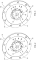
- Fig. 2
- eine Ansicht der Kupplungseinrichtung gemäß
Fig. 1 in zusammengebautem Zustand bei hergestellter Drehverbindung, - Fig. 3
- eine Ansicht der in
Fig. 2 wiedergegebenen Kupplungseinrichtung bei gelöster Drehverbindung, und - Fig. 4
- eine Schnittdarstellung des Fahrzeuglüfter, für ein landwirtschaftliches Fahrzeug, mit einer Kupplungseinrichtung.
-
Fig. 1 zeigt in einer Explosionsdarstellung die Bestandteile eines Ausführungsbeispiels des erfindungsgemäßen Fahrzeuglüfter mit einer Kupplungseinrichtung. - Die Kupplungseinrichtung 10 umfasst entlang einer gemeinsamen Drehachse 12 ein antriebsseitiges Kupplungselement 14 sowie ein abtriebsseitiges Kupplungselement 16.
- Das antriebsseitige Kupplungselement 14 weist eine Nabe 18 auf (siehe hierzu auch
Fig. 4 ). Entlang eines Außenumfangs 20 der Nabe 18 ist eine Vielzahl radial verschwenkbarer Sperrklauen 22 angebracht, die jeweils mittels eines Federelements 24 in eine inFig. 2 wiedergegebene ausgelenkte Sperrstellung vorgespannt sind, sodass sich eine Drehverbindung zwischen den beiden Kupplungselementen 14, 16 herstellen lässt. - Hierzu ist entlang eines Innenumfangs 26 des abtriebsseitigen Kupplungselements 16 eine Vielzahl von Kupplungsrampen 28 zur Ineingriffnahme einer jeweiligen der Sperrklauen 22 ausgebildet. Wie in
Fig. 2 zu erkennen ist, liegen bei hergestellter Drehverbindung die Sperrklauen 22 mit einem stirnseitigen Ende 30 an einem im Wesentlichen quer zur Drehrichtung verlaufenden Rampenende 32 an. - Umgekehrt lassen sich die Sperrklauen 22 zur Freigabe der Drehverbindung entlang einer Innenkontur 34 der Kupplungsrampen 28 entgegen der mittels des jeweiligen Federelements 24 erzeugten Vorspannung aus der ausgelenkten Sperrstellung heraus radial nach innen wegdrängen, wobei diese zumindest teilweise von einer jeweiligen Ausnehmung 36 entlang des Außenumfangs 20 der Nabe 18 aufgenommen werden. Dies ist beispielsweise bei gegensinnigen Drehrichtungen der beiden Kupplungselemente 14, 16 zueinander oder aber dann der Fall, wenn die abtriebsseitige Drehzahl größer ist als die antriebsseitige Drehzahl. Ein derartiger Freilaufbetrieb ist in
Fig. 3 gezeigt. Im Ergebnis überträgt die Kupplungseinrichtung 10, genauer gesagt der durch die Sperrklauen 22 bzw. die Kupplungsrampen 28 gebildete Sperrmechanismus, ein Drehmoment nur in der vorgegebenen Drehrichtung. - Vorliegend entspricht die Anzahl der Kupplungsrampen 28 derjenigen der Sperrklauen 22. Alternativ kann diese jedoch auch ein Vielfaches davon betragen. Beispielsgemäß sind insgesamt 4 Sperrklauen 22 bzw. Kupplungsrampen 28 gleichmäßig entlang des Außenumfangs 20 der Nabe 18 bzw. des Innenumfangs 26 des abtriebsseitigen Kupplungselements 16 verteilt angeordnet. Zusätzlich weisen die Sperrklauen 22 einen bezüglich des Außenumfangs 20 der Nabe 18 tangential gebogenen Verlauf derart auf, dass diese jeweils in einem Schulterbereich 38 an der Innenkontur 34 der Kupplungsrampen 28 anliegen. Aufgrund der so geschaffenen Vergrößerung des Anlagefläche kann im Freilaufbetrieb ein reibungsbedingter Verschleiß von Sperrklauen 22 und Kupplungsrampen 28 maßgeblich verringert werden. Beide Teile bestehen hierbei aus oberflächengehärtetem Stahl.
-
Fig. 4 zeigt ferner eine Schnittdarstellung der Kupplungseinrichtung 10 in an dem erfindungsgemäßen Fahrzeuglüfter 40 eingebautem Zustand. Wie sich durch Vergleich mitFig. 1 erkennen lässt, ist das antriebsseitige Kupplungselement 14 mittels eines Rillenkugellagers 42 innerhalb des abtriebsseitigen Kupplungselements 16 drehbar aufgenommen. - Das Rillenkugellager 42 umfasst einen inneren Laufring 44 und einen äußeren Laufring 46. Der äußere Laufring 46 ist in eine an dem abtriebsseitigen Kupplungselement 16 ausgebildete Aufnahmeöffnung 48 eingesetzt und darin mittels eines Sicherungsrings 50, der in eine an der Aufnahmeöffnung 48 umlaufende Innennut 52 eingreift, im Wesentlichen spielfrei festgelegt. Der innere Laufring 44 hingegen ist auf einen an der Nabe 18 ausgebildeten Befestigungsvorsprung 54 aufgesteckt und liegt dort an einem umlaufenden Kragen 56 an. Auf der dem Kragen 56 gegenüberliegenden Seite des Rillenkugellagers 42 befindet sich ein in eine umlaufende Außennut 58 am Befestigungsvorsprung 54 eingreifender weiterer Sicherungsring 60, der das Rillenkugellager 42 im Wesentlichen spielfrei auf dem Befestigungsvorsprung 54 festlegt.
- An dem abtriebsseitigen Kupplungselement 16 ist ein Befestigungsflansch 62 zur Montage eines in
Fig. 4 gezeigten Lüfterrads 64 ausgebildet. Das aus faserverstärktem Kunststoff bestehende Lüfterrad 64 umfasst eine Vielzahl von Lüfterflügeln 66, die der Erzeugung eines axialen Kühlluftstroms 68 dienen. Das Lüfterrad 64 ist mittels einer Befestigungsnabe 70 mit einem an dem Befestigungsflansch 62 vorgesehenen Lochkranz 72 verschraubt. - Die von dem antriebsseitigen Kupplungselement 14 umfasste Nabe 18 weist ein Innengewinde 74 auf, in das eine mit einer Riemenscheibe 76 in Verbindung stehende Antriebswelle 78 eingeschraubt ist, sodass Nabe 18 und Antriebswelle 78 miteinander drehverbunden sind. Die Riemenscheibe 76 ist Bestandteil eines von einem Verbrennungsmotor 80 antreibbaren Riementriebs 82, der sich im Motorraum 84 eines nicht dargestellten landwirtschaftlichen Fahrzeugs, beispielsweise eines landwirtschaftlichen Traktors, befindet.
Claims (4)
- Fahrzeuglüfter für ein landwirtschaftliches Fahrzeug, mit einer Kupplungseinrichtung (10), umfassend ein antriebsseitiges Kupplungselement (14) und ein abtriebsseitiges Kupplungselement (16), wobei das antriebsseitige Kupplungselement (14) eine Nabe (18) aufweist, dadurch gekennzeichnet, dass entlang eines Außenumfangs (20) der Nabe (18) eine Vielzahl radial verschwenkbarer Sperrklauen (22) angebracht ist, die jeweils mittels eines Federelements (24) in eine ausgelenkte Sperrstellung vorgespannt sind, sodass sich eine Drehverbindung zwischen den beiden Kupplungselementen (14, 16) herstellen lässt, wobei entlang eines Innenumfangs (26) des abtriebsseitigen Kupplungselements (16) eine Vielzahl von Kupplungsrampen (28) zur Ineingriffnahme einer jeweiligen der Sperrklauen (22) vorgesehen ist, sodass zwischen den beiden Kupplungselementen (14, 16) ein Sperrmechanismus (22, 28) derart ausgebildet ist, dass eine zwischen den Kupplungselementen (14, 16) hergestellte Drehverbindung freigegeben wird, wenn eine antriebsseitige Drehzahl gegenüber einer abtriebsseitigen Drehzahl abfällt.
- Fahrzeuglüfter nach Anspruch 1, dadurch gekennzeichnet, dass die Anzahl der Kupplungsrampen (28) derjenigen der Sperrklauen (22) entspricht oder ein Vielfaches davon beträgt.
- Fahrzeuglüfter nach Anspruch 1 oder 2, dadurch gekennzeichnet, dass an dem abtriebsseitigen Kupplungselement (16) ein Befestigungsflansch (62) zur Montage eines Lüfterrads (64) ausgebildet ist.
- Fahrzeuglüfter nach wenigstens einem der vorhergehenden Ansprüche, dadurch gekennzeichnet, dass das antriebsseitige Kupplungselement (14) mittels eines Rillenkugellagers (42) innerhalb des abtriebsseitigen Kupplungselements (16) drehbar aufgenommen ist.
Applications Claiming Priority (1)
| Application Number | Priority Date | Filing Date | Title |
|---|---|---|---|
| DE102021128076.1A DE102021128076A1 (de) | 2021-10-28 | 2021-10-28 | Kupplungseinrichtung für einen Fahrzeuglüfter |
Publications (2)
| Publication Number | Publication Date |
|---|---|
| EP4174337A1 EP4174337A1 (de) | 2023-05-03 |
| EP4174337B1 true EP4174337B1 (de) | 2024-08-28 |
Family
ID=83598411
Family Applications (1)
| Application Number | Title | Priority Date | Filing Date |
|---|---|---|---|
| EP22199849.5A Active EP4174337B1 (de) | 2021-10-28 | 2022-10-05 | Kupplungseinrichtung für einen fahrzeuglüfter |
Country Status (3)
| Country | Link |
|---|---|
| US (1) | US11713707B2 (de) |
| EP (1) | EP4174337B1 (de) |
| DE (1) | DE102021128076A1 (de) |
Family Cites Families (9)
| Publication number | Priority date | Publication date | Assignee | Title |
|---|---|---|---|---|
| US3053363A (en) | 1959-07-31 | 1962-09-11 | Schwitzer Corp | Air sensing fan drive |
| US4271945A (en) | 1978-06-05 | 1981-06-09 | General Motors Corporation | Electrically actuated viscous fan clutch |
| US6129193A (en) | 1997-08-29 | 2000-10-10 | American Cooling Systems, L.L.C. | Electric fan clutch |
| DE102004040810A1 (de) | 2004-08-24 | 2006-03-02 | Ina-Schaeffler Kg | Vorrichtung zur Dämpfung von Drehschwingungen |
| US8091696B2 (en) | 2007-01-12 | 2012-01-10 | GM Global Technology Operations LLC | Rocker clutch assembly |
| NZ591640A (en) | 2008-09-10 | 2012-11-30 | Smith International | Locking clutch for downhole drill motor with centrifugal force to disengage rotor from stator |
| US9121461B1 (en) | 2014-06-09 | 2015-09-01 | Kit Masters | Two speed clutch with viscous system |
| US10197134B2 (en) | 2014-09-30 | 2019-02-05 | Ford Global Technologies, Llc | Hybrid transmission having electro-magnetically actuated pawl clutch |
| DE102016211145B4 (de) | 2016-06-22 | 2022-03-31 | Schaeffler Technologies AG & Co. KG | Aktorlos betätigte Riemenscheibenkupplung mit Fliehkraft- und Trägheitsstellelementen |
-
2021
- 2021-10-28 DE DE102021128076.1A patent/DE102021128076A1/de active Pending
-
2022
- 2022-09-29 US US17/936,439 patent/US11713707B2/en active Active
- 2022-10-05 EP EP22199849.5A patent/EP4174337B1/de active Active
Also Published As
| Publication number | Publication date |
|---|---|
| US20230139344A1 (en) | 2023-05-04 |
| US11713707B2 (en) | 2023-08-01 |
| EP4174337A1 (de) | 2023-05-03 |
| DE102021128076A1 (de) | 2023-05-04 |
Similar Documents
| Publication | Publication Date | Title |
|---|---|---|
| DE60026062T2 (de) | Freilaufkupplungseinrichtung | |
| DE112012001892B4 (de) | Überbrückungsvorrichtung für einen Drehmomentwandler | |
| DE10123615B4 (de) | Drehmomentwandler mit Überbrückungskupplung | |
| DE102007042205A1 (de) | Flüssigkeitsreibungskupplung, beispielsweise für Fahrzeuganwendungen | |
| DE112011100816B4 (de) | Anfahreinheit mit Flüssigkeitskupplung | |
| DE112012001668T5 (de) | Überbrückungsvorrichtung für einen Drehmomentwandler | |
| EP2340378B1 (de) | Torsionsschwingungsdämpferanordnung, insbesondere für den antriebsstrang eines fahrzeugs | |
| EP1914434A2 (de) | Drehmomentübertragungseinrichtung | |
| DE102007017046A1 (de) | Hydrodynamische Drehmomentübertragungsvorrichtung und dafür verwendete Überbrückungsvorrichtung | |
| DE112016006905T5 (de) | Drehmomentwandler für Fahrzeuge | |
| DE10156041B4 (de) | Hydrodynamische Kopplungseinrichtung | |
| DE112015004982T5 (de) | Überbrückungsvorrichtung für einen Drehmomentwandler | |
| DE102008061589A1 (de) | Kupplungsscheibe | |
| WO2015082223A1 (de) | Regelbare pumpe für eine verbrennungskraftmaschine | |
| DE102011017653A1 (de) | Hydrodynamische Kopplungsanordnung, insbesondere hydrodynamischer Drehmomentwandler | |
| DE602004002493T2 (de) | Flüssigkeitskupplung | |
| DE102016219677A1 (de) | Drehmomentwandler mit Leerlaufverriegelung | |
| DE102007047635A1 (de) | Drehmomentbegrenzungskupplung | |
| DE112014001888T5 (de) | Überbrückungsvorrichtung für einen Drehmomentwandler | |
| DE102008008864A1 (de) | Überbrückungsvorrichtung und mit einer solchen ausgestattete hydraulische Drehmomentübertragungsvorrichtung | |
| DE10061460A1 (de) | Reibungskupplung | |
| DE69800683T2 (de) | Fliehkraft-Ausrückkupplung | |
| EP4174337A1 (de) | Kupplungseinrichtung für einen fahrzeuglüfter | |
| WO2002063186A1 (de) | Hydrodynamische kopplungseinrichtung | |
| DE102011086985A1 (de) | Selbstnachstellende Kupplung |
Legal Events
| Date | Code | Title | Description |
|---|---|---|---|
| PUAI | Public reference made under article 153(3) epc to a published international application that has entered the european phase |
Free format text: ORIGINAL CODE: 0009012 |
|
| STAA | Information on the status of an ep patent application or granted ep patent |
Free format text: STATUS: THE APPLICATION HAS BEEN PUBLISHED |
|
| AK | Designated contracting states |
Kind code of ref document: A1 Designated state(s): AL AT BE BG CH CY CZ DE DK EE ES FI FR GB GR HR HU IE IS IT LI LT LU LV MC ME MK MT NL NO PL PT RO RS SE SI SK SM TR |
|
| STAA | Information on the status of an ep patent application or granted ep patent |
Free format text: STATUS: REQUEST FOR EXAMINATION WAS MADE |
|
| 17P | Request for examination filed |
Effective date: 20231103 |
|
| RBV | Designated contracting states (corrected) |
Designated state(s): AL AT BE BG CH CY CZ DE DK EE ES FI FR GB GR HR HU IE IS IT LI LT LU LV MC ME MK MT NL NO PL PT RO RS SE SI SK SM TR |
|
| GRAP | Despatch of communication of intention to grant a patent |
Free format text: ORIGINAL CODE: EPIDOSNIGR1 |
|
| STAA | Information on the status of an ep patent application or granted ep patent |
Free format text: STATUS: GRANT OF PATENT IS INTENDED |
|
| INTG | Intention to grant announced |
Effective date: 20240429 |
|
| GRAS | Grant fee paid |
Free format text: ORIGINAL CODE: EPIDOSNIGR3 |
|
| GRAA | (expected) grant |
Free format text: ORIGINAL CODE: 0009210 |
|
| STAA | Information on the status of an ep patent application or granted ep patent |
Free format text: STATUS: THE PATENT HAS BEEN GRANTED |
|
| AK | Designated contracting states |
Kind code of ref document: B1 Designated state(s): AL AT BE BG CH CY CZ DE DK EE ES FI FR GB GR HR HU IE IS IT LI LT LU LV MC ME MK MT NL NO PL PT RO RS SE SI SK SM TR |
|
| REG | Reference to a national code |
Ref country code: CH Ref legal event code: EP |
|
| REG | Reference to a national code |
Ref country code: DE Ref legal event code: R096 Ref document number: 502022001566 Country of ref document: DE |
|
| REG | Reference to a national code |
Ref country code: IE Ref legal event code: FG4D Free format text: LANGUAGE OF EP DOCUMENT: GERMAN |
|
| REG | Reference to a national code |
Ref country code: LT Ref legal event code: MG9D |
|
| PG25 | Lapsed in a contracting state [announced via postgrant information from national office to epo] |
Ref country code: NO Free format text: LAPSE BECAUSE OF FAILURE TO SUBMIT A TRANSLATION OF THE DESCRIPTION OR TO PAY THE FEE WITHIN THE PRESCRIBED TIME-LIMIT Effective date: 20241128 |
|
| PG25 | Lapsed in a contracting state [announced via postgrant information from national office to epo] |
Ref country code: NL Free format text: LAPSE BECAUSE OF FAILURE TO SUBMIT A TRANSLATION OF THE DESCRIPTION OR TO PAY THE FEE WITHIN THE PRESCRIBED TIME-LIMIT Effective date: 20240828 Ref country code: PL Free format text: LAPSE BECAUSE OF FAILURE TO SUBMIT A TRANSLATION OF THE DESCRIPTION OR TO PAY THE FEE WITHIN THE PRESCRIBED TIME-LIMIT Effective date: 20240828 Ref country code: GR Free format text: LAPSE BECAUSE OF FAILURE TO SUBMIT A TRANSLATION OF THE DESCRIPTION OR TO PAY THE FEE WITHIN THE PRESCRIBED TIME-LIMIT Effective date: 20241129 Ref country code: PT Free format text: LAPSE BECAUSE OF FAILURE TO SUBMIT A TRANSLATION OF THE DESCRIPTION OR TO PAY THE FEE WITHIN THE PRESCRIBED TIME-LIMIT Effective date: 20241230 Ref country code: FI Free format text: LAPSE BECAUSE OF FAILURE TO SUBMIT A TRANSLATION OF THE DESCRIPTION OR TO PAY THE FEE WITHIN THE PRESCRIBED TIME-LIMIT Effective date: 20240828 |
|
| PG25 | Lapsed in a contracting state [announced via postgrant information from national office to epo] |
Ref country code: BG Free format text: LAPSE BECAUSE OF FAILURE TO SUBMIT A TRANSLATION OF THE DESCRIPTION OR TO PAY THE FEE WITHIN THE PRESCRIBED TIME-LIMIT Effective date: 20240828 |
|
| PG25 | Lapsed in a contracting state [announced via postgrant information from national office to epo] |
Ref country code: LV Free format text: LAPSE BECAUSE OF FAILURE TO SUBMIT A TRANSLATION OF THE DESCRIPTION OR TO PAY THE FEE WITHIN THE PRESCRIBED TIME-LIMIT Effective date: 20240828 |
|
| REG | Reference to a national code |
Ref country code: NL Ref legal event code: MP Effective date: 20240828 |
|
| PG25 | Lapsed in a contracting state [announced via postgrant information from national office to epo] |
Ref country code: IS Free format text: LAPSE BECAUSE OF FAILURE TO SUBMIT A TRANSLATION OF THE DESCRIPTION OR TO PAY THE FEE WITHIN THE PRESCRIBED TIME-LIMIT Effective date: 20241228 |
|
| PG25 | Lapsed in a contracting state [announced via postgrant information from national office to epo] |
Ref country code: HR Free format text: LAPSE BECAUSE OF FAILURE TO SUBMIT A TRANSLATION OF THE DESCRIPTION OR TO PAY THE FEE WITHIN THE PRESCRIBED TIME-LIMIT Effective date: 20240828 |
|
| PG25 | Lapsed in a contracting state [announced via postgrant information from national office to epo] |
Ref country code: ES Free format text: LAPSE BECAUSE OF FAILURE TO SUBMIT A TRANSLATION OF THE DESCRIPTION OR TO PAY THE FEE WITHIN THE PRESCRIBED TIME-LIMIT Effective date: 20240828 Ref country code: RS Free format text: LAPSE BECAUSE OF FAILURE TO SUBMIT A TRANSLATION OF THE DESCRIPTION OR TO PAY THE FEE WITHIN THE PRESCRIBED TIME-LIMIT Effective date: 20241128 |
|
| PG25 | Lapsed in a contracting state [announced via postgrant information from national office to epo] |
Ref country code: RS Free format text: LAPSE BECAUSE OF FAILURE TO SUBMIT A TRANSLATION OF THE DESCRIPTION OR TO PAY THE FEE WITHIN THE PRESCRIBED TIME-LIMIT Effective date: 20241128 Ref country code: PT Free format text: LAPSE BECAUSE OF FAILURE TO SUBMIT A TRANSLATION OF THE DESCRIPTION OR TO PAY THE FEE WITHIN THE PRESCRIBED TIME-LIMIT Effective date: 20241230 Ref country code: PL Free format text: LAPSE BECAUSE OF FAILURE TO SUBMIT A TRANSLATION OF THE DESCRIPTION OR TO PAY THE FEE WITHIN THE PRESCRIBED TIME-LIMIT Effective date: 20240828 Ref country code: NO Free format text: LAPSE BECAUSE OF FAILURE TO SUBMIT A TRANSLATION OF THE DESCRIPTION OR TO PAY THE FEE WITHIN THE PRESCRIBED TIME-LIMIT Effective date: 20241128 Ref country code: NL Free format text: LAPSE BECAUSE OF FAILURE TO SUBMIT A TRANSLATION OF THE DESCRIPTION OR TO PAY THE FEE WITHIN THE PRESCRIBED TIME-LIMIT Effective date: 20240828 Ref country code: LV Free format text: LAPSE BECAUSE OF FAILURE TO SUBMIT A TRANSLATION OF THE DESCRIPTION OR TO PAY THE FEE WITHIN THE PRESCRIBED TIME-LIMIT Effective date: 20240828 Ref country code: IS Free format text: LAPSE BECAUSE OF FAILURE TO SUBMIT A TRANSLATION OF THE DESCRIPTION OR TO PAY THE FEE WITHIN THE PRESCRIBED TIME-LIMIT Effective date: 20241228 Ref country code: HR Free format text: LAPSE BECAUSE OF FAILURE TO SUBMIT A TRANSLATION OF THE DESCRIPTION OR TO PAY THE FEE WITHIN THE PRESCRIBED TIME-LIMIT Effective date: 20240828 Ref country code: GR Free format text: LAPSE BECAUSE OF FAILURE TO SUBMIT A TRANSLATION OF THE DESCRIPTION OR TO PAY THE FEE WITHIN THE PRESCRIBED TIME-LIMIT Effective date: 20241129 Ref country code: FI Free format text: LAPSE BECAUSE OF FAILURE TO SUBMIT A TRANSLATION OF THE DESCRIPTION OR TO PAY THE FEE WITHIN THE PRESCRIBED TIME-LIMIT Effective date: 20240828 Ref country code: ES Free format text: LAPSE BECAUSE OF FAILURE TO SUBMIT A TRANSLATION OF THE DESCRIPTION OR TO PAY THE FEE WITHIN THE PRESCRIBED TIME-LIMIT Effective date: 20240828 Ref country code: BG Free format text: LAPSE BECAUSE OF FAILURE TO SUBMIT A TRANSLATION OF THE DESCRIPTION OR TO PAY THE FEE WITHIN THE PRESCRIBED TIME-LIMIT Effective date: 20240828 |
|
| PG25 | Lapsed in a contracting state [announced via postgrant information from national office to epo] |
Ref country code: DK Free format text: LAPSE BECAUSE OF FAILURE TO SUBMIT A TRANSLATION OF THE DESCRIPTION OR TO PAY THE FEE WITHIN THE PRESCRIBED TIME-LIMIT Effective date: 20240828 Ref country code: RO Free format text: LAPSE BECAUSE OF FAILURE TO SUBMIT A TRANSLATION OF THE DESCRIPTION OR TO PAY THE FEE WITHIN THE PRESCRIBED TIME-LIMIT Effective date: 20240828 Ref country code: SM Free format text: LAPSE BECAUSE OF FAILURE TO SUBMIT A TRANSLATION OF THE DESCRIPTION OR TO PAY THE FEE WITHIN THE PRESCRIBED TIME-LIMIT Effective date: 20240828 |
|
| PG25 | Lapsed in a contracting state [announced via postgrant information from national office to epo] |
Ref country code: EE Free format text: LAPSE BECAUSE OF FAILURE TO SUBMIT A TRANSLATION OF THE DESCRIPTION OR TO PAY THE FEE WITHIN THE PRESCRIBED TIME-LIMIT Effective date: 20240828 |
|
| PG25 | Lapsed in a contracting state [announced via postgrant information from national office to epo] |
Ref country code: CZ Free format text: LAPSE BECAUSE OF FAILURE TO SUBMIT A TRANSLATION OF THE DESCRIPTION OR TO PAY THE FEE WITHIN THE PRESCRIBED TIME-LIMIT Effective date: 20240828 |
|
| PG25 | Lapsed in a contracting state [announced via postgrant information from national office to epo] |
Ref country code: SK Free format text: LAPSE BECAUSE OF FAILURE TO SUBMIT A TRANSLATION OF THE DESCRIPTION OR TO PAY THE FEE WITHIN THE PRESCRIBED TIME-LIMIT Effective date: 20240828 |
|
| REG | Reference to a national code |
Ref country code: DE Ref legal event code: R097 Ref document number: 502022001566 Country of ref document: DE |
|
| PLBE | No opposition filed within time limit |
Free format text: ORIGINAL CODE: 0009261 |
|
| STAA | Information on the status of an ep patent application or granted ep patent |
Free format text: STATUS: NO OPPOSITION FILED WITHIN TIME LIMIT |
|
| PG25 | Lapsed in a contracting state [announced via postgrant information from national office to epo] |
Ref country code: MC Free format text: LAPSE BECAUSE OF FAILURE TO SUBMIT A TRANSLATION OF THE DESCRIPTION OR TO PAY THE FEE WITHIN THE PRESCRIBED TIME-LIMIT Effective date: 20240828 |
|
| PG25 | Lapsed in a contracting state [announced via postgrant information from national office to epo] |
Ref country code: LU Free format text: LAPSE BECAUSE OF NON-PAYMENT OF DUE FEES Effective date: 20241005 Ref country code: BE Free format text: LAPSE BECAUSE OF NON-PAYMENT OF DUE FEES Effective date: 20241031 |
|
| 26N | No opposition filed |
Effective date: 20250530 |
|
| REG | Reference to a national code |
Ref country code: BE Ref legal event code: MM Effective date: 20241031 |
|
| PG25 | Lapsed in a contracting state [announced via postgrant information from national office to epo] |
Ref country code: SE Free format text: LAPSE BECAUSE OF FAILURE TO SUBMIT A TRANSLATION OF THE DESCRIPTION OR TO PAY THE FEE WITHIN THE PRESCRIBED TIME-LIMIT Effective date: 20240828 |
|
| PG25 | Lapsed in a contracting state [announced via postgrant information from national office to epo] |
Ref country code: IE Free format text: LAPSE BECAUSE OF NON-PAYMENT OF DUE FEES Effective date: 20241005 |
|
| PGFP | Annual fee paid to national office [announced via postgrant information from national office to epo] |
Ref country code: DE Payment date: 20250919 Year of fee payment: 4 |
|
| PGFP | Annual fee paid to national office [announced via postgrant information from national office to epo] |
Ref country code: AT Payment date: 20260113 Year of fee payment: 4 |
|
| PGFP | Annual fee paid to national office [announced via postgrant information from national office to epo] |
Ref country code: IT Payment date: 20251031 Year of fee payment: 4 |
|
| PGFP | Annual fee paid to national office [announced via postgrant information from national office to epo] |
Ref country code: FR Payment date: 20251027 Year of fee payment: 4 |
|
| PG25 | Lapsed in a contracting state [announced via postgrant information from national office to epo] |
Ref country code: CY Free format text: LAPSE BECAUSE OF FAILURE TO SUBMIT A TRANSLATION OF THE DESCRIPTION OR TO PAY THE FEE WITHIN THE PRESCRIBED TIME-LIMIT; INVALID AB INITIO Effective date: 20221005 |
|
| PG25 | Lapsed in a contracting state [announced via postgrant information from national office to epo] |
Ref country code: HU Free format text: LAPSE BECAUSE OF FAILURE TO SUBMIT A TRANSLATION OF THE DESCRIPTION OR TO PAY THE FEE WITHIN THE PRESCRIBED TIME-LIMIT; INVALID AB INITIO Effective date: 20221005 |