EP4173883B1 - Battery swapping platform, battery swapping station, and battery swapping method - Google Patents
Battery swapping platform, battery swapping station, and battery swapping method Download PDFInfo
- Publication number
- EP4173883B1 EP4173883B1 EP21827865.3A EP21827865A EP4173883B1 EP 4173883 B1 EP4173883 B1 EP 4173883B1 EP 21827865 A EP21827865 A EP 21827865A EP 4173883 B1 EP4173883 B1 EP 4173883B1
- Authority
- EP
- European Patent Office
- Prior art keywords
- battery
- vehicle
- opening
- accommodating
- dismounting
- Prior art date
- Legal status (The legal status is an assumption and is not a legal conclusion. Google has not performed a legal analysis and makes no representation as to the accuracy of the status listed.)
- Active
Links
Images


Classifications
-
- B—PERFORMING OPERATIONS; TRANSPORTING
- B60—VEHICLES IN GENERAL
- B60L—PROPULSION OF ELECTRICALLY-PROPELLED VEHICLES; SUPPLYING ELECTRIC POWER FOR AUXILIARY EQUIPMENT OF ELECTRICALLY-PROPELLED VEHICLES; ELECTRODYNAMIC BRAKE SYSTEMS FOR VEHICLES IN GENERAL; MAGNETIC SUSPENSION OR LEVITATION FOR VEHICLES; MONITORING OPERATING VARIABLES OF ELECTRICALLY-PROPELLED VEHICLES; ELECTRIC SAFETY DEVICES FOR ELECTRICALLY-PROPELLED VEHICLES
- B60L53/00—Methods of charging batteries, specially adapted for electric vehicles; Charging stations or on-board charging equipment therefor; Exchange of energy storage elements in electric vehicles
- B60L53/80—Exchanging energy storage elements, e.g. removable batteries
-
- B—PERFORMING OPERATIONS; TRANSPORTING
- B60—VEHICLES IN GENERAL
- B60L—PROPULSION OF ELECTRICALLY-PROPELLED VEHICLES; SUPPLYING ELECTRIC POWER FOR AUXILIARY EQUIPMENT OF ELECTRICALLY-PROPELLED VEHICLES; ELECTRODYNAMIC BRAKE SYSTEMS FOR VEHICLES IN GENERAL; MAGNETIC SUSPENSION OR LEVITATION FOR VEHICLES; MONITORING OPERATING VARIABLES OF ELECTRICALLY-PROPELLED VEHICLES; ELECTRIC SAFETY DEVICES FOR ELECTRICALLY-PROPELLED VEHICLES
- B60L50/00—Electric propulsion with power supplied within the vehicle
- B60L50/50—Electric propulsion with power supplied within the vehicle using propulsion power supplied by batteries or fuel cells
- B60L50/60—Electric propulsion with power supplied within the vehicle using propulsion power supplied by batteries or fuel cells using power supplied by batteries
- B60L50/64—Constructional details of batteries specially adapted for electric vehicles
-
- B—PERFORMING OPERATIONS; TRANSPORTING
- B60—VEHICLES IN GENERAL
- B60L—PROPULSION OF ELECTRICALLY-PROPELLED VEHICLES; SUPPLYING ELECTRIC POWER FOR AUXILIARY EQUIPMENT OF ELECTRICALLY-PROPELLED VEHICLES; ELECTRODYNAMIC BRAKE SYSTEMS FOR VEHICLES IN GENERAL; MAGNETIC SUSPENSION OR LEVITATION FOR VEHICLES; MONITORING OPERATING VARIABLES OF ELECTRICALLY-PROPELLED VEHICLES; ELECTRIC SAFETY DEVICES FOR ELECTRICALLY-PROPELLED VEHICLES
- B60L50/00—Electric propulsion with power supplied within the vehicle
- B60L50/50—Electric propulsion with power supplied within the vehicle using propulsion power supplied by batteries or fuel cells
- B60L50/60—Electric propulsion with power supplied within the vehicle using propulsion power supplied by batteries or fuel cells using power supplied by batteries
- B60L50/66—Arrangements of batteries
-
- B—PERFORMING OPERATIONS; TRANSPORTING
- B66—HOISTING; LIFTING; HAULING
- B66F—HOISTING, LIFTING, HAULING OR PUSHING, NOT OTHERWISE PROVIDED FOR, e.g. DEVICES WHICH APPLY A LIFTING OR PUSHING FORCE DIRECTLY TO THE SURFACE OF A LOAD
- B66F7/00—Lifting frames, e.g. for lifting vehicles; Platform lifts
- B66F7/06—Lifting frames, e.g. for lifting vehicles; Platform lifts with platforms supported by levers for vertical movement
- B66F7/065—Scissor linkages, i.e. X-configuration
-
- B—PERFORMING OPERATIONS; TRANSPORTING
- B66—HOISTING; LIFTING; HAULING
- B66F—HOISTING, LIFTING, HAULING OR PUSHING, NOT OTHERWISE PROVIDED FOR, e.g. DEVICES WHICH APPLY A LIFTING OR PUSHING FORCE DIRECTLY TO THE SURFACE OF A LOAD
- B66F7/00—Lifting frames, e.g. for lifting vehicles; Platform lifts
- B66F7/24—Lifting frames, e.g. for lifting vehicles; Platform lifts for raising or lowering vehicles by their own power
- B66F7/243—Ramps
-
- B—PERFORMING OPERATIONS; TRANSPORTING
- B66—HOISTING; LIFTING; HAULING
- B66F—HOISTING, LIFTING, HAULING OR PUSHING, NOT OTHERWISE PROVIDED FOR, e.g. DEVICES WHICH APPLY A LIFTING OR PUSHING FORCE DIRECTLY TO THE SURFACE OF A LOAD
- B66F7/00—Lifting frames, e.g. for lifting vehicles; Platform lifts
- B66F7/28—Constructional details, e.g. end stops, pivoting supporting members, sliding runners adjustable to load dimensions
-
- B—PERFORMING OPERATIONS; TRANSPORTING
- B60—VEHICLES IN GENERAL
- B60K—ARRANGEMENT OR MOUNTING OF PROPULSION UNITS OR OF TRANSMISSIONS IN VEHICLES; ARRANGEMENT OR MOUNTING OF PLURAL DIVERSE PRIME-MOVERS IN VEHICLES; AUXILIARY DRIVES FOR VEHICLES; INSTRUMENTATION OR DASHBOARDS FOR VEHICLES; ARRANGEMENTS IN CONNECTION WITH COOLING, AIR INTAKE, GAS EXHAUST OR FUEL SUPPLY OF PROPULSION UNITS IN VEHICLES
- B60K1/00—Arrangement or mounting of electrical propulsion units
- B60K1/04—Arrangement or mounting of electrical propulsion units of the electric storage means for propulsion
- B60K2001/0455—Removal or replacement of the energy storages
- B60K2001/0472—Removal or replacement of the energy storages from below
-
- B—PERFORMING OPERATIONS; TRANSPORTING
- B60—VEHICLES IN GENERAL
- B60L—PROPULSION OF ELECTRICALLY-PROPELLED VEHICLES; SUPPLYING ELECTRIC POWER FOR AUXILIARY EQUIPMENT OF ELECTRICALLY-PROPELLED VEHICLES; ELECTRODYNAMIC BRAKE SYSTEMS FOR VEHICLES IN GENERAL; MAGNETIC SUSPENSION OR LEVITATION FOR VEHICLES; MONITORING OPERATING VARIABLES OF ELECTRICALLY-PROPELLED VEHICLES; ELECTRIC SAFETY DEVICES FOR ELECTRICALLY-PROPELLED VEHICLES
- B60L2200/00—Type of vehicles
- B60L2200/26—Rail vehicles
-
- B—PERFORMING OPERATIONS; TRANSPORTING
- B60—VEHICLES IN GENERAL
- B60L—PROPULSION OF ELECTRICALLY-PROPELLED VEHICLES; SUPPLYING ELECTRIC POWER FOR AUXILIARY EQUIPMENT OF ELECTRICALLY-PROPELLED VEHICLES; ELECTRODYNAMIC BRAKE SYSTEMS FOR VEHICLES IN GENERAL; MAGNETIC SUSPENSION OR LEVITATION FOR VEHICLES; MONITORING OPERATING VARIABLES OF ELECTRICALLY-PROPELLED VEHICLES; ELECTRIC SAFETY DEVICES FOR ELECTRICALLY-PROPELLED VEHICLES
- B60L2240/00—Control parameters of input or output; Target parameters
- B60L2240/10—Vehicle control parameters
-
- B—PERFORMING OPERATIONS; TRANSPORTING
- B60—VEHICLES IN GENERAL
- B60Y—INDEXING SCHEME RELATING TO ASPECTS CROSS-CUTTING VEHICLE TECHNOLOGY
- B60Y2200/00—Type of vehicle
- B60Y2200/60—Industrial applications, e.g. pipe inspection vehicles
- B60Y2200/62—Conveyors, floor conveyors
-
- Y—GENERAL TAGGING OF NEW TECHNOLOGICAL DEVELOPMENTS; GENERAL TAGGING OF CROSS-SECTIONAL TECHNOLOGIES SPANNING OVER SEVERAL SECTIONS OF THE IPC; TECHNICAL SUBJECTS COVERED BY FORMER USPC CROSS-REFERENCE ART COLLECTIONS [XRACs] AND DIGESTS
- Y02—TECHNOLOGIES OR APPLICATIONS FOR MITIGATION OR ADAPTATION AGAINST CLIMATE CHANGE
- Y02T—CLIMATE CHANGE MITIGATION TECHNOLOGIES RELATED TO TRANSPORTATION
- Y02T10/00—Road transport of goods or passengers
- Y02T10/60—Other road transportation technologies with climate change mitigation effect
- Y02T10/70—Energy storage systems for electromobility, e.g. batteries
-
- Y—GENERAL TAGGING OF NEW TECHNOLOGICAL DEVELOPMENTS; GENERAL TAGGING OF CROSS-SECTIONAL TECHNOLOGIES SPANNING OVER SEVERAL SECTIONS OF THE IPC; TECHNICAL SUBJECTS COVERED BY FORMER USPC CROSS-REFERENCE ART COLLECTIONS [XRACs] AND DIGESTS
- Y02—TECHNOLOGIES OR APPLICATIONS FOR MITIGATION OR ADAPTATION AGAINST CLIMATE CHANGE
- Y02T—CLIMATE CHANGE MITIGATION TECHNOLOGIES RELATED TO TRANSPORTATION
- Y02T10/00—Road transport of goods or passengers
- Y02T10/60—Other road transportation technologies with climate change mitigation effect
- Y02T10/7072—Electromobility specific charging systems or methods for batteries, ultracapacitors, supercapacitors or double-layer capacitors
-
- Y—GENERAL TAGGING OF NEW TECHNOLOGICAL DEVELOPMENTS; GENERAL TAGGING OF CROSS-SECTIONAL TECHNOLOGIES SPANNING OVER SEVERAL SECTIONS OF THE IPC; TECHNICAL SUBJECTS COVERED BY FORMER USPC CROSS-REFERENCE ART COLLECTIONS [XRACs] AND DIGESTS
- Y02—TECHNOLOGIES OR APPLICATIONS FOR MITIGATION OR ADAPTATION AGAINST CLIMATE CHANGE
- Y02T—CLIMATE CHANGE MITIGATION TECHNOLOGIES RELATED TO TRANSPORTATION
- Y02T90/00—Enabling technologies or technologies with a potential or indirect contribution to GHG emissions mitigation
- Y02T90/10—Technologies relating to charging of electric vehicles
- Y02T90/12—Electric charging stations
Definitions
- Embodiments of the disclosure relate to a vehicle battery swap technology, and in particular, to a battery swap platform, a battery swap station, and a battery swap method.
- a battery swap station is an automated apparatus for swapping a battery for an electric vehicle.
- published document WO2019100656A1 discloses a battery swap platform and a battery swap station for electrical vehicles, wherein the battery swap platform is configured to park a vehicle thereon and is provided with a battery swap mechanism thereon for performing a battery swap for the vehicle.
- Published documents CN103072558A and CN102795204B each disclose another battery swap platform or system having a battery swap platform for parking a vehicle thereon and a battery swap mechanism arranged in the platform, respectively.
- an existing battery swap platform 1 is mainly composed of a parking platform 11, a vehicle hoister 12, a wheel alignment mechanism 13, and a rail guided vehicle (RGV) 14.
- RSV rail guided vehicle
- the parking platform 11 is configured to park a vehicle
- the wheel alignment mechanism 13 is configured to position the vehicle at a designated position of the parking platform 11
- the vehicle hoister 12 is configured to lift the vehicle parked on the parking platform 11 to a set height
- the rail guided vehicle 14 is configured to implement horizontal transport of a battery, vertical lifting of the battery, and a battery mounting/dismounting operation.
- the vehicle hoister 12 since the rail guided vehicle 14 directly travels on the parking platform 11, when the battery mounting/dismounting operation is performed for the vehicle on the parking platform 11, the vehicle hoister 12 must substantially lift the vehicle, leaving a moving space for the rail guided vehicle 14. As a result, a driver and a passenger have to leave the vehicle when the battery is being swapped for the vehicle. This not only increases the total time taken for vehicle battery swap, but also brings a poor battery swap experience to the vehicle owner, and there is also a risk of falling while the vehicle is being substantially lifted.
- the battery is completely exposed in a visible range during conveying, which is easy to cause the risks of a collision to personnel and the battery being contaminated by intrusion of foreign objects, posing a potential safety hazard.
- the invention provides a battery swap platform, a battery swap station, and a battery swap method as defined in the appended set of claims, to overcome or at least partially solve the foregoing problems.
- the battery mounting/dismounting mechanism is transferred to the accommodating mechanism below the parking mechanism, and the battery mounting/dismounting mechanism can be lifted relative to the accommodating mechanism to extend out of the accommodating structure, and perform a battery mounting/dismounting operation for the vehicle. After the battery mounting/dismounting operation is completed, the battery mounting/dismounting mechanism can be lowered relative to the accommodating mechanism so as to be entirely received in the accommodating mechanism.
- the vehicle hoisting mechanism only needs to slightly lift the vehicle to a horizontal state, and a driver and a passenger do not need to leave the vehicle, which can improve the battery swap experience of the vehicle owner, reduce the total time taken for the vehicle battery swap operation, and improve the safety of the battery swap operation.
- the first embodiment of the disclosure provides a battery swap platform 2, which mainly includes a parking mechanism 21, an accommodating mechanism 22, an opening and closing mechanism 23, and a battery mounting/dismounting mechanism 24.
- the parking mechanism 21 is configured to park a vehicle.
- the parking mechanism 21 is further provided with a wheel alignment device 211 configured to position wheels of the vehicle, such that the vehicle is stably parked on the parking mechanism 21.
- the accommodating mechanism 22 is arranged below the vehicle parked on the parking mechanism 21 and has an opening 211.
- the parking mechanism 21 includes a first parking sub-mechanism 21A and a second parking sub-mechanism 21B, and the accommodating mechanism 22 is naturally formed by the first parking sub-mechanism 21A and the second parking sub-mechanism 21B that are arranged separately from each other.
- the opening and closing mechanism 23 is arranged on the accommodating mechanism 22 and can move relative to the accommodating mechanism 22 to open or close the opening 221 of the accommodating mechanism 22.
- the opening and closing mechanism 23 may include at least one compartment door, and the opening and closing mechanism 23 can slide relative to the accommodating mechanism 22 to open or close the opening of the accommodating mechanism 22.
- the opening and closing mechanism 23 may have a bidirectional door opening structure formed by two compartment doors 231 and 232, or may be designed as a unilateral door opening structure.
- the opening and closing mechanism 23 may be designed as a single-layer compartment door structure including a single layer of panel (i.e., the embodiment shown in FIGS. 4A and 4B ), or the opening and closing mechanism 23 may be designed as a multi-layer linkage compartment door structure including multiple layers of panels (i.e., the embodiment shown in FIGS. 4C and 4D ).
- the single-layer compartment door structure is simple in design, which can reduce manufacturing costs, while the design of the multi-layer linkage compartment door structure can reduce the space occupied by the opening and closing mechanism 23 when in an open state.
- a material of the compartment doors 231, 232 in the opening and closing mechanism 23 is not limited in the disclosure, and the compartment doors may be made of a material with sufficient hardness, or may be designed as soft material doors (e.g., retractable doors and roller shutter doors).
- the accommodating mechanism 22 when the opening and closing mechanism 23 opens the opening 221 of the accommodating mechanism 22, the accommodating mechanism 22 may be in communication with the parking mechanism 21 located above the accommodating mechanism. When the opening and closing mechanism 23 closes the opening 221 of the accommodating mechanism 22, the accommodating mechanism 22 is separated from the parking mechanism 21 by means of the opening and closing mechanism 23.
- the battery mounting/dismounting mechanism 24 is arranged in the accommodating mechanism 22 and can be lifted or lowered relative to the accommodating mechanism 22.
- the battery mounting/dismounting mechanism 24 includes a rail guided vehicle.
- the battery mounting/dismounting mechanism 24 can be lifted relative to the accommodating mechanism 22 to extend out of the accommodating mechanism 22 through the opening 221, and perform a battery mounting/dismounting operation for the vehicle parked on the parking mechanism 21.
- the battery mounting/dismounting mechanism 24 can be lifted or lowered relative to the accommodating mechanism 22 to switch between an operating state and a non-operating state.
- the opening and closing mechanism 23 opens the opening 221 of the accommodating mechanism 22
- the battery mounting/dismounting mechanism 24 can be lifted relative to the accommodating mechanism 22 to switch to the operating state.
- at least a part of the battery mounting/dismounting mechanism 24 can extend out of the accommodating mechanism 22 through the opening 221, so as to perform a battery mounting/dismounting operation for the vehicle parked on the parking mechanism 21.
- the battery mounting/dismounting mechanism 24 when the opening and closing mechanism 23 closes the opening 221 of the accommodating mechanism 22, the battery mounting/dismounting mechanism 24 may be in the non-operating state. In this state, the battery mounting/dismounting mechanism 24 is entirely received in the accommodating mechanism 22.
- the vehicle when the opening and closing mechanism 23 closes the opening 221 of the accommodating mechanism 22, the vehicle is enabled to enter or leave the parking mechanism 21.
- the battery swap platform 2 further includes a vehicle hoisting mechanism 25.
- the vehicle hoisting mechanism 25 is arranged in the accommodating mechanism 22 and can be lifted or lowered relative to the accommodating mechanism 22.
- the vehicle hoisting mechanism 25 can be lifted relative to the accommodating mechanism 22 to extend out of the accommodating mechanism 22 through the opening 221, and slightly lift the vehicle 6 parked on the parking mechanism 21, to cause the vehicle 6 to be arranged horizontally.
- the vehicle hoisting mechanism 25 may also be arranged on the parking mechanism 21, to slightly lift the vehicle 6 parked on the parking mechanism 21, so as to cause the vehicle 6 to be arranged horizontally.
- the vehicle hoisting mechanism 25 may also cause the vehicle to be arranged horizontally by slightly lifting the wheel alignment device 211.
- the vehicle hoisting mechanism 25 may be a scissor lift, a lead screw hoister, a hydraulic jack hoister, etc., and the disclosure is not limited thereto. Other mechanical arrangements that can be used to lift the vehicle are applicable, which will not be limited in the disclosure.
- the second embodiment of the disclosure provides a battery swap station 3.
- the battery swap station 3 mainly includes the battery swap platform 2 described in the first embodiment, a battery storage mechanism 4, and a battery docking structure 5.
- the battery swap platform 2 is configured to mount or dismount a battery on or from a vehicle 6, the battery storage mechanism 4 is configured to store the battery, and the battery docking mechanism 5 connects the battery swap platform 2 to the battery storage mechanism 4 and is configured to convey the battery between the battery swap platform 2 and the battery storage mechanism 4.
- the battery storage mechanism 4 may include two battery storage racks 41A, 41B and a lifting device 42 arranged between the two battery storage racks 41A, 41B.
- each of the battery storage racks 41A, 41B includes a plurality of battery compartments 411 arranged in a stacked manner, and the lifting device 42 can be lifted or lowered in a vertical direction of the battery storage racks 41A, 41B so as to be docked with one of the plurality of battery compartments 411.
- a plurality of battery storage racks 41A, 41B may also be arranged side-by-side on a single side of the lifting device 42, and the lifting device 42 can move in a horizontal direction of the battery storage racks 41A, 41B so as to be docked with one of the plurality of battery storage racks 41A, 41B.
- a guide rail may be installed below the lifting device 42, so that the lifting device 42 can move along the guide rail between the plurality of battery storage racks 41A, 41B arranged side-by-side, thereby increasing the capacity of the battery compartment 411.
- the battery docking mechanism 5 may be implemented by means of various structural designs.
- the battery docking mechanism 5 may be a conveying mechanism such as a roller conveying line, a chain conveying line and a belt conveying line, but the disclosure is not limited thereto.
- the battery docking mechanism 5 may also be presented by means of a guide rail cooperating with a docking vehicle, but the disclosure is not limited thereto.
- the battery swap station 3 may further include charging devices (not shown) which are respectively arranged in the battery compartments 411 and are configured to be electrically connected to batteries stored in the battery compartments 411 for charging.
- the battery swap station 3 may be further provided with an electrical room 31 and a control room 32.
- the electrical room 31 is responsible for charging control and management of each charging device, and the control room 32 is responsible for motion logic control of each component in the entire battery swap station 3.
- FIG. 9 shows main steps of a battery swap method according to the third embodiment of the disclosure.
- the battery swap method provided according to the embodiment of the disclosure is applied to the battery swap platform 2 described in the first embodiment, and mainly includes the following steps.
- the vehicle hoisting mechanism 25 is arranged in the accommodating mechanism 22 and is taken for description.
- step S91 the opening and closing mechanism 23 of the battery swap platform 2 is controlled to close the opening 221 of the accommodating mechanism 22, to enable the vehicle 6 to enter and be parked on the parking mechanism 21.
- a wheel alignment device 211 may be used to position wheels of the vehicle 6, such that the vehicle 6 is positioned at a designated position of the parking mechanism 21.
- step S92 the opening and closing mechanism 23 of the battery swap platform 11 is controlled to open the opening 221 of the accommodating mechanism 22 after the vehicle 6 is positioned on the parking mechanism 21.
- step S93 the vehicle hoisting mechanism 25 is controlled to be lifted relative to the accommodating mechanism 22, so as to slightly lift the vehicle 6 on the parking mechanism 21, to cause the vehicle 6 to be arranged horizontally (in a state shown in FIG. 8A ).
- step S94 the battery mounting/dismounting mechanism 24 is controlled to be lifted relative to the accommodating mechanism 22 to switch from a non-operating state to an operating state so as to extend out of the accommodating mechanism 22 through the opening 221 after the vehicle reaches the arranged horizontally state, and to perform a battery mounting/dismounting operation for the vehicle 6 (in a state shown in FIG. 8B ).
- step S95 the battery mounting/dismounting mechanism 24 is first controlled to be lowered relative to the accommodating mechanism 22 to switch from the operating state to the non-operating state after the battery mounting/dismounting operation is completed for the vehicle 6, and then the vehicle hoisting mechanism 25 is controlled to be lowered relative to the accommodating mechanism 22, so that the vehicle 6 is lowered back to the parking mechanism 21.
- step S96 the opening and closing mechanism 23 is controlled to close the opening 221 of the accommodating mechanism 22, to enable the vehicle 6 to leave the parking mechanism 21.
- the accommodating mechanism is arranged below the parking mechanism to transfer the battery mounting/dismounting mechanism to below the parking mechanism.
- the accommodating mechanism When the accommodating mechanism is in the closed state, the vehicle is enabled to enter or leave the parking mechanism.
- the battery mounting/dismounting mechanism can extend out of the accommodating mechanism by opening the accommodating mechanism, and perform a battery mounting/dismounting operation for the vehicle.
- battery swap can be completed without the need for a driver and a passenger to leave the vehicle, which can improve battery swap experience of the vehicle owner.
- the embodiments of the disclosure can significantly reduce a risk of accidental falling of the vehicle, improve safety of battery swap operation, and reduce the total time taken for vehicle battery swap.
Landscapes
- Engineering & Computer Science (AREA)
- Mechanical Engineering (AREA)
- Life Sciences & Earth Sciences (AREA)
- Power Engineering (AREA)
- Transportation (AREA)
- Geology (AREA)
- Structural Engineering (AREA)
- Sustainable Development (AREA)
- Sustainable Energy (AREA)
- Arrangement Or Mounting Of Propulsion Units For Vehicles (AREA)
- Electric Propulsion And Braking For Vehicles (AREA)
- Circuits Of Receivers In General (AREA)
Description
- Embodiments of the disclosure relate to a vehicle battery swap technology, and in particular, to a battery swap platform, a battery swap station, and a battery swap method.
- With the development of automobile technology, new energy vehicles have become the mainstream development trend of automobile industry. A battery swap station is an automated apparatus for swapping a battery for an electric vehicle. For example, published document
WO2019100656A1 discloses a battery swap platform and a battery swap station for electrical vehicles, wherein the battery swap platform is configured to park a vehicle thereon and is provided with a battery swap mechanism thereon for performing a battery swap for the vehicle. Published documentsCN103072558A andCN102795204B each disclose another battery swap platform or system having a battery swap platform for parking a vehicle thereon and a battery swap mechanism arranged in the platform, respectively. - As shown in
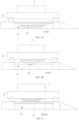
FIG. 1 , an existingbattery swap platform 1 is mainly composed of aparking platform 11, avehicle hoister 12, awheel alignment mechanism 13, and a rail guided vehicle (RGV) 14. - The
parking platform 11 is configured to park a vehicle, thewheel alignment mechanism 13 is configured to position the vehicle at a designated position of theparking platform 11, thevehicle hoister 12 is configured to lift the vehicle parked on theparking platform 11 to a set height, and the rail guidedvehicle 14 is configured to implement horizontal transport of a battery, vertical lifting of the battery, and a battery mounting/dismounting operation. - In the prior art, since the rail guided
vehicle 14 directly travels on theparking platform 11, when the battery mounting/dismounting operation is performed for the vehicle on theparking platform 11, thevehicle hoister 12 must substantially lift the vehicle, leaving a moving space for the rail guidedvehicle 14. As a result, a driver and a passenger have to leave the vehicle when the battery is being swapped for the vehicle. This not only increases the total time taken for vehicle battery swap, but also brings a poor battery swap experience to the vehicle owner, and there is also a risk of falling while the vehicle is being substantially lifted. - Furthermore, in the prior art, the battery is completely exposed in a visible range during conveying, which is easy to cause the risks of a collision to personnel and the battery being contaminated by intrusion of foreign objects, posing a potential safety hazard.
- In view of the foregoing problems, the invention provides a battery swap platform, a battery swap station, and a battery swap method as defined in the appended set of claims, to overcome or at least partially solve the foregoing problems.
- It can be seen from the foregoing technical solutions that, in the battery swap platform provided in the embodiments of the disclosure, the battery mounting/dismounting mechanism is transferred to the accommodating mechanism below the parking mechanism, and the battery mounting/dismounting mechanism can be lifted relative to the accommodating mechanism to extend out of the accommodating structure, and perform a battery mounting/dismounting operation for the vehicle. After the battery mounting/dismounting operation is completed, the battery mounting/dismounting mechanism can be lowered relative to the accommodating mechanism so as to be entirely received in the accommodating mechanism. Therefore, there is no need to reserve an operating space for the battery mounting/dismounting mechanism, so that when the battery mounting/dismounting operation is performed for the vehicle, the vehicle hoisting mechanism only needs to slightly lift the vehicle to a horizontal state, and a driver and a passenger do not need to leave the vehicle, which can improve the battery swap experience of the vehicle owner, reduce the total time taken for the vehicle battery swap operation, and improve the safety of the battery swap operation.
- To illustrate the technical solutions in embodiments of the disclosure or in the prior art more clearly, a brief introduction to the drawings required for the embodiments or the prior art will be provided below. Obviously, the drawings in the following description are merely some of the embodiments of the disclosure, and those of ordinary skills in the art would also obtain other drawings according to these drawings.
-
FIG. 1 is a schematic diagram of an overall structure of an existing battery swap platform; -
FIG. 2 is a schematic diagram of an overall structure of a battery swap platform according to a first embodiment of the disclosure; -
FIG. 3 is a schematic exploded view of the battery swap platform according to the first embodiment of the disclosure; -
FIGS. 4A and4D are schematic embodiment diagrams of an opening and closing mechanism for opening or closing an opening of an accommodating mechanism according to the first embodiment of the disclosure; -
FIGS. 5A and 5B are schematic embodiment diagrams of a vehicle hoisting mechanism according to the the invention; -
FIG. 6 is another schematic embodiment diagram of the vehicle hoisting mechanism according to the first embodiment of the disclosure; -
FIGS. 7A and7C are different schematic embodiment diagrams of a battery swap station according to a second embodiment of the disclosure; -
FIGS. 8A and8B are schematic embodiment diagrams of a battery swap method according to a third embodiment of the disclosure; and -
FIG. 9 is a schematic flowchart of the battery swap method according to the invention. - 1: Battery swap platform; 11: Parking platform; 12: Vehicle hoister; 13: Wheel alignment mechanism; 14: Rail guided vehicle; 2: Battery swap platform; 21: Parking mechanism; 21A: First parking sub-mechanism; 21B: Second parking sub-mechanism; 211: Wheel alignment device; 22: Accommodating mechanism; 221: Opening; 23: Opening and closing mechanism; 231, 232: Compartment door; 24: Battery mounting/dismounting mechanism; 25: Vehicle hoisting mechanism; 3: Battery swap station; 31: Electrical room; 32: Control room; 4: Battery storage mechanism; 41A, 41B: Battery storage rack; 411: Battery compartment; 42: Lifting device; 5: Battery docking mechanism; 6: Vehicle
- To enable those skilled in the art to better understand the technical solutions in the embodiments of the disclosure, the technical solutions in the embodiments of the disclosure will be clearly and completely described below in conjunction with the accompanying drawings in the embodiments of the disclosure.
- The specific implementation of the embodiments of the disclosure will be further described below with reference to the accompanying drawings in the embodiments of the disclosure.
- As shown in
FIGS. 2 and3 , the first embodiment of the disclosure provides abattery swap platform 2, which mainly includes aparking mechanism 21, anaccommodating mechanism 22, an opening andclosing mechanism 23, and a battery mounting/dismounting mechanism 24. - The
parking mechanism 21 is configured to park a vehicle. - Optionally, the
parking mechanism 21 is further provided with awheel alignment device 211 configured to position wheels of the vehicle, such that the vehicle is stably parked on theparking mechanism 21. - The
accommodating mechanism 22 is arranged below the vehicle parked on theparking mechanism 21 and has anopening 211. - In this embodiment, the
parking mechanism 21 includes afirst parking sub-mechanism 21A and asecond parking sub-mechanism 21B, and theaccommodating mechanism 22 is naturally formed by thefirst parking sub-mechanism 21A and thesecond parking sub-mechanism 21B that are arranged separately from each other. - The opening and
closing mechanism 23 is arranged on theaccommodating mechanism 22 and can move relative to theaccommodating mechanism 22 to open or close theopening 221 of theaccommodating mechanism 22. - Optionally, the opening and
closing mechanism 23 may include at least one compartment door, and the opening andclosing mechanism 23 can slide relative to theaccommodating mechanism 22 to open or close the opening of theaccommodating mechanism 22. - Referring to
FIGS. 4A and4B , in this embodiment, the opening andclosing mechanism 23 may have a bidirectional door opening structure formed by twocompartment doors - In another embodiment, the opening and
closing mechanism 23 may be designed as a single-layer compartment door structure including a single layer of panel (i.e., the embodiment shown inFIGS. 4A and4B ), or the opening andclosing mechanism 23 may be designed as a multi-layer linkage compartment door structure including multiple layers of panels (i.e., the embodiment shown inFIGS. 4C and 4D ). The single-layer compartment door structure is simple in design, which can reduce manufacturing costs, while the design of the multi-layer linkage compartment door structure can reduce the space occupied by the opening andclosing mechanism 23 when in an open state. - In addition, a material of the
compartment doors closing mechanism 23 is not limited in the disclosure, and the compartment doors may be made of a material with sufficient hardness, or may be designed as soft material doors (e.g., retractable doors and roller shutter doors). - In this embodiment, when the opening and
closing mechanism 23 opens theopening 221 of theaccommodating mechanism 22, theaccommodating mechanism 22 may be in communication with theparking mechanism 21 located above the accommodating mechanism. When the opening andclosing mechanism 23 closes theopening 221 of theaccommodating mechanism 22, theaccommodating mechanism 22 is separated from theparking mechanism 21 by means of the opening andclosing mechanism 23. - The battery mounting/
dismounting mechanism 24 is arranged in theaccommodating mechanism 22 and can be lifted or lowered relative to theaccommodating mechanism 22. - Optionally, the battery mounting/
dismounting mechanism 24 includes a rail guided vehicle. - In this embodiment, when the opening and
closing mechanism 23 opens theopening 221 of theaccommodating mechanism 22, the battery mounting/dismounting mechanism 24 can be lifted relative to theaccommodating mechanism 22 to extend out of theaccommodating mechanism 22 through theopening 221, and perform a battery mounting/dismounting operation for the vehicle parked on theparking mechanism 21. - Specifically, the battery mounting/
dismounting mechanism 24 can be lifted or lowered relative to theaccommodating mechanism 22 to switch between an operating state and a non-operating state. When the opening andclosing mechanism 23 opens theopening 221 of theaccommodating mechanism 22, the battery mounting/dismounting mechanism 24 can be lifted relative to theaccommodating mechanism 22 to switch to the operating state. In this state, at least a part of the battery mounting/dismounting mechanism 24 can extend out of theaccommodating mechanism 22 through theopening 221, so as to perform a battery mounting/dismounting operation for the vehicle parked on theparking mechanism 21. - In another embodiment, when the opening and
closing mechanism 23 closes theopening 221 of theaccommodating mechanism 22, the battery mounting/dismounting mechanism 24 may be in the non-operating state. In this state, the battery mounting/dismounting mechanism 24 is entirely received in theaccommodating mechanism 22. - In this embodiment, when the opening and
closing mechanism 23 closes theopening 221 of theaccommodating mechanism 22, the vehicle is enabled to enter or leave theparking mechanism 21. - In another embodiment, the
battery swap platform 2 further includes avehicle hoisting mechanism 25. - As shown in
FIGS. 5A and 5B , in an embodiment, thevehicle hoisting mechanism 25 is arranged in theaccommodating mechanism 22 and can be lifted or lowered relative to theaccommodating mechanism 22. - As shown in
FIG. 5A , when the opening andclosing mechanism 23 closes theopening 221 of theaccommodating mechanism 22, thevehicle hoisting mechanism 25 is entirely received in theaccommodating mechanism 22. - As shown in
FIG. 5B , when the opening andclosing mechanism 23 opens theopening 221 of theaccommodating mechanism 22, thevehicle hoisting mechanism 25 can be lifted relative to theaccommodating mechanism 22 to extend out of theaccommodating mechanism 22 through theopening 221, and slightly lift thevehicle 6 parked on theparking mechanism 21, to cause thevehicle 6 to be arranged horizontally. - As shown in
FIG. 6 , in another embodiment, thevehicle hoisting mechanism 25 may also be arranged on theparking mechanism 21, to slightly lift thevehicle 6 parked on theparking mechanism 21, so as to cause thevehicle 6 to be arranged horizontally. - In another embodiment, the
vehicle hoisting mechanism 25 may also cause the vehicle to be arranged horizontally by slightly lifting thewheel alignment device 211. - In this embodiment, the
vehicle hoisting mechanism 25 may be a scissor lift, a lead screw hoister, a hydraulic jack hoister, etc., and the disclosure is not limited thereto. Other mechanical arrangements that can be used to lift the vehicle are applicable, which will not be limited in the disclosure. - The second embodiment of the disclosure provides a
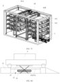
battery swap station 3. - As shown in
FIGS. 7A to 7C , thebattery swap station 3 according to this embodiment of the disclosure mainly includes thebattery swap platform 2 described in the first embodiment, abattery storage mechanism 4, and abattery docking structure 5. - In this embodiment, the
battery swap platform 2 is configured to mount or dismount a battery on or from avehicle 6, thebattery storage mechanism 4 is configured to store the battery, and thebattery docking mechanism 5 connects thebattery swap platform 2 to thebattery storage mechanism 4 and is configured to convey the battery between thebattery swap platform 2 and thebattery storage mechanism 4. - In this embodiment, the
battery storage mechanism 4 may include twobattery storage racks lifting device 42 arranged between the twobattery storage racks - Optionally, each of the
battery storage racks battery compartments 411 arranged in a stacked manner, and thelifting device 42 can be lifted or lowered in a vertical direction of thebattery storage racks - Optionally, a plurality of
battery storage racks lifting device 42, and thelifting device 42 can move in a horizontal direction of thebattery storage racks battery storage racks - For example, a guide rail may be installed below the lifting
device 42, so that thelifting device 42 can move along the guide rail between the plurality ofbattery storage racks battery compartment 411. - The
battery docking mechanism 5 may be implemented by means of various structural designs. For example, thebattery docking mechanism 5 may be a conveying mechanism such as a roller conveying line, a chain conveying line and a belt conveying line, but the disclosure is not limited thereto. Thebattery docking mechanism 5 may also be presented by means of a guide rail cooperating with a docking vehicle, but the disclosure is not limited thereto. - In another embodiment, the
battery swap station 3 may further include charging devices (not shown) which are respectively arranged in the battery compartments 411 and are configured to be electrically connected to batteries stored in the battery compartments 411 for charging. - Referring to
FIGS. 7A and 7B , in another embodiment, thebattery swap station 3 may be further provided with anelectrical room 31 and acontrol room 32. Theelectrical room 31 is responsible for charging control and management of each charging device, and thecontrol room 32 is responsible for motion logic control of each component in the entirebattery swap station 3. -
FIG. 9 shows main steps of a battery swap method according to the third embodiment of the disclosure. The battery swap method provided according to the embodiment of the disclosure is applied to thebattery swap platform 2 described in the first embodiment, and mainly includes the following steps. - According to the invention, the
vehicle hoisting mechanism 25 is arranged in theaccommodating mechanism 22 and is taken for description. - In step S91, the opening and
closing mechanism 23 of thebattery swap platform 2 is controlled to close theopening 221 of theaccommodating mechanism 22, to enable thevehicle 6 to enter and be parked on theparking mechanism 21. - In this embodiment, a
wheel alignment device 211 may be used to position wheels of thevehicle 6, such that thevehicle 6 is positioned at a designated position of theparking mechanism 21. - In step S92, the opening and
closing mechanism 23 of thebattery swap platform 11 is controlled to open theopening 221 of theaccommodating mechanism 22 after thevehicle 6 is positioned on theparking mechanism 21. - In step S93, the
vehicle hoisting mechanism 25 is controlled to be lifted relative to theaccommodating mechanism 22, so as to slightly lift thevehicle 6 on theparking mechanism 21, to cause thevehicle 6 to be arranged horizontally (in a state shown inFIG. 8A ). - In step S94, the battery mounting/
dismounting mechanism 24 is controlled to be lifted relative to theaccommodating mechanism 22 to switch from a non-operating state to an operating state so as to extend out of theaccommodating mechanism 22 through theopening 221 after the vehicle reaches the arranged horizontally state, and to perform a battery mounting/dismounting operation for the vehicle 6 (in a state shown inFIG. 8B ). - In step S95, the battery mounting/
dismounting mechanism 24 is first controlled to be lowered relative to theaccommodating mechanism 22 to switch from the operating state to the non-operating state after the battery mounting/dismounting operation is completed for thevehicle 6, and then thevehicle hoisting mechanism 25 is controlled to be lowered relative to theaccommodating mechanism 22, so that thevehicle 6 is lowered back to theparking mechanism 21. - In step S96, the opening and
closing mechanism 23 is controlled to close theopening 221 of theaccommodating mechanism 22, to enable thevehicle 6 to leave theparking mechanism 21. - In summary, in the battery swap platform provided in the embodiments of the disclosure, the accommodating mechanism is arranged below the parking mechanism to transfer the battery mounting/dismounting mechanism to below the parking mechanism. When the accommodating mechanism is in the closed state, the vehicle is enabled to enter or leave the parking mechanism. When the vehicle is parked on the parking mechanism, the battery mounting/dismounting mechanism can extend out of the accommodating mechanism by opening the accommodating mechanism, and perform a battery mounting/dismounting operation for the vehicle. In this way, in the disclosure, there is no need to reserve a moving space for the battery mounting/dismounting mechanism on a parking mechanism (the parking platform), so that during the battery mounting/dismounting operation, the vehicle only needs to be slightly lifted, so that the vehicle is in a horizontally arranged state. Therefore, battery swap can be completed without the need for a driver and a passenger to leave the vehicle, which can improve battery swap experience of the vehicle owner. Compared with the prior art in which it is required to substantially lift the vehicle to a preset height, the embodiments of the disclosure can significantly reduce a risk of accidental falling of the vehicle, improve safety of battery swap operation, and reduce the total time taken for vehicle battery swap.
- Finally, it should be noted that the foregoing embodiments are merely used for illustrating rather than limiting the technical solutions of the embodiments of the disclosure.
Claims (8)
- A battery swap platform (2), comprising:a parking mechanism (21) configured to park a vehicle (6);an accommodating mechanism (22), which is arranged below the vehicle (6) parked on the parking mechanism (21), and which has an opening (221);an opening and closing mechanism (23) arranged on the accommodating mechanism (22) and capable of moving relative to the accommodating mechanism (22) to open or close the opening (221) of the accommodating mechanism (22);a battery mounting/dismounting mechanism (24) ; anda vehicle hoisting mechanism (25) configured to slightly lift the vehicle (6) parked on the parking mechanism (21), to cause the vehicle (6) to be arranged horizontally,wherein when the opening and closing mechanism (23) opens the opening (221) of the accommodating mechanism (22), the battery mounting/dismounting mechanism (24) is capable of being lifted relative to the accommodating mechanism (24) to extend out of the accommodating mechanism (22) through the opening (221), and performing a battery mounting/dismounting operation for the vehicle (6),wherein both the battery mounting/dismounting mechanism (24) and the vehicle hoisting mechanism (25) are arranged in the accommodating mechanism (22) and configured to be lifted or lowered relative to the accommodating mechanism (22).
- The battery swap platform (2) according to claim 1, wherein the opening and closing mechanism (23) comprises one of a bidirectional door opening structure and a unilateral door opening structure.
- The battery swap platform (2) according to claim 1, wherein the opening and closing mechanism (23) comprises one of a single-layer compartment door structure and a multi-layer linkage layered door structure.
- The battery swap platform (2) according to claim 1, wherein the battery mounting/dismounting mechanism (24) is capable of being lifted or lowered relative to the accommodating mechanism (22) to switch between an operating state and a non-operating state, wherein when the battery mounting/dismounting mechanism (24) is in the operating state, the battery mounting/dismounting mechanism (24) is capable of extending out of the accommodating mechanism (22) through the opening (221), and the battery mounting/dismounting mechanism (24) is configured such that when it is in the non-operating state, the battery mounting/dismounting mechanism (24) is entirely received in the accommodating mechanism (22).
- The battery swap platform (2) according to claim 4, wherein the opening and closing mechanism (23) is configured such that when it closes the opening (221) of the accommodating mechanism (22), the vehicle (6) is enabled to enter or leave the parking mechanism (21).
- The battery swap platform (2) according to claim 1, wherein the parking mechanism (21) further comprises:
a wheel alignment device (211) configured to position wheels of the vehicle (6), such that the vehicle (6) is parked on the parking mechanism (21). - A battery swap station (3), comprising:a battery swap platform (2) according to any one of claims 1 to 6 configured to mount or dismount a battery on or from a vehicle (6);a battery storage mechanism (4) configured to store the battery; anda battery docking mechanism (5) configured to connect the battery swap platform (2) to the battery storage mechanism (4), and to convey the battery between the battery swap platform (2) and the battery storage mechanism (4).
- A battery swap method applied to a battery swap platform according to any one of claims 1 to 6, the method comprising:controlling the opening and closing mechanism to close the opening of the accommodating mechanism, to enable the vehicle to enter the parking mechanism (S91);controlling the opening and closing mechanism to open the opening of the accommodating mechanism after the vehicle is parked on the parking mechanism (S92);controlling the vehicle hoisting mechanism to be lifted relative to the accommodating mechanism, so as to slightly lift the vehicle on the parking mechanism, to cause the vehicle to be arranged horizontally (S93);controlling the battery mounting/dismounting mechanism to switch from a non-operating state to an operating state so as to extend out of the accommodating mechanism through the opening, to perform a battery mounting/dismounting operation for the vehicle (S94);controlling the battery mounting/dismounting mechanism to switch from the operating state to the non-operating state so as to be completely received in the accommodating mechanism after the battery mounting/dismounting mechanism completes the battery mounting/dismounting operation for the vehicle; andcontrolling the opening and closing mechanism to close the opening of the accommodating mechanism, to enable the vehicle to leave the parking mechanism (S96).
Applications Claiming Priority (2)
| Application Number | Priority Date | Filing Date | Title |
|---|---|---|---|
| CN202010596061.4A CN112140939A (en) | 2020-06-24 | 2020-06-24 | Battery changing platform, battery changing station and battery changing method |
| PCT/CN2021/095155 WO2021258944A1 (en) | 2020-06-24 | 2021-05-21 | Battery swapping platform, battery swapping station, and battery swapping method |
Publications (3)
| Publication Number | Publication Date |
|---|---|
| EP4173883A1 EP4173883A1 (en) | 2023-05-03 |
| EP4173883A4 EP4173883A4 (en) | 2023-11-29 |
| EP4173883B1 true EP4173883B1 (en) | 2025-01-22 |
Family
ID=73887777
Family Applications (1)
| Application Number | Title | Priority Date | Filing Date |
|---|---|---|---|
| EP21827865.3A Active EP4173883B1 (en) | 2020-06-24 | 2021-05-21 | Battery swapping platform, battery swapping station, and battery swapping method |
Country Status (5)
| Country | Link |
|---|---|
| US (1) | US20230242002A1 (en) |
| EP (1) | EP4173883B1 (en) |
| CN (1) | CN112140939A (en) |
| TW (1) | TWI768653B (en) |
| WO (1) | WO2021258944A1 (en) |
Families Citing this family (10)
| Publication number | Priority date | Publication date | Assignee | Title |
|---|---|---|---|---|
| CN112140939A (en) * | 2020-06-24 | 2020-12-29 | 武汉蔚来能源有限公司 | Battery changing platform, battery changing station and battery changing method |
| CN111634207A (en) * | 2020-06-24 | 2020-09-08 | 武汉蔚来能源有限公司 | Power exchange platform, power exchange station and power exchange method |
| EP4212382B1 (en) * | 2021-08-27 | 2025-08-06 | Contemporary Amperex Technology (Hong Kong) Limited | Battery swapping platform and a battery swapping station |
| CN115284950B (en) * | 2021-11-30 | 2024-10-18 | 奥动新能源汽车科技有限公司 | Battery swap tray for electric vehicle and electric vehicle |
| USD1057202S1 (en) * | 2021-11-30 | 2025-01-07 | Aulton New Energy Automotive Technology Group | Power exchange station |
| CN217320101U (en) * | 2022-01-29 | 2022-08-30 | 时代电服科技有限公司 | Battery changing platform and battery changing station |
| WO2023201507A1 (en) * | 2022-04-19 | 2023-10-26 | 时代电服科技有限公司 | Battery swapping method and battery swapping system |
| US20240383368A1 (en) * | 2023-05-16 | 2024-11-21 | Ample, Inc. | Battery-Exchange System and Service Station |
| CN121157850A (en) * | 2023-12-29 | 2025-12-19 | 奥动新能源股份有限公司 | Level changing table |
| CN222432093U (en) * | 2024-03-18 | 2025-02-07 | 武汉蔚来能源有限公司 | Battery swap platform and battery swap station |
Family Cites Families (28)
| Publication number | Priority date | Publication date | Assignee | Title |
|---|---|---|---|---|
| TW570253U (en) * | 2003-04-30 | 2004-01-01 | Wen-Tsung Liu | Animation teaching plotter |
| IL218924A (en) * | 2012-03-29 | 2016-03-31 | Better Place GmbH | Battery exchange system and method for electric vehicles |
| CN102795204B (en) * | 2012-08-16 | 2015-02-11 | 王俊 | Electric car chassis battery charging and replacing station and battery replacing method using same |
| CN103072558A (en) * | 2013-02-15 | 2013-05-01 | 佘德全 | Power battery quick replacement method, equipment, system and layout |
| US9688252B2 (en) * | 2014-04-23 | 2017-06-27 | Tesla, Inc. | Battery swapping system and techniques |
| CN106627514A (en) * | 2016-12-29 | 2017-05-10 | 西安航天精密机电研究所 | Chassis type battery replacing robot and battery replacing method |
| CN109501756A (en) * | 2017-09-12 | 2019-03-22 | 上海蔚来汽车有限公司 | Electric car moves electric system certainly |
| CN207860149U (en) * | 2017-11-22 | 2018-09-14 | 蔚来汽车有限公司 | Automatic battery replacing platform and battery replacing station of electric automobile |
| CN108177634A (en) * | 2017-12-15 | 2018-06-19 | 蔚来汽车有限公司 | Charging and battery-replacing station |
| CN109532778B (en) * | 2018-09-04 | 2025-04-11 | 武汉蔚来能源有限公司 | Vehicle battery swap platform |
| CN109334628B (en) * | 2018-10-18 | 2024-01-19 | 博众精工科技股份有限公司 | Automobile power exchanging station |
| CN110027518A (en) * | 2018-10-19 | 2019-07-19 | 上海蔚来汽车有限公司 | Transport device, connecting mechanism and change electric system |
| CN109204249A (en) * | 2018-11-27 | 2019-01-15 | 高红丽 | Electric passenger vehicle battery altering station and its battery change method |
| CN110001600B (en) * | 2018-12-07 | 2023-08-01 | 蔚来控股有限公司 | Quick power change system and quick power change method |
| CN111301358A (en) * | 2020-03-04 | 2020-06-19 | 博众精工科技股份有限公司 | Single-cache battery swapping system, battery swapping method and battery swapping station |
| CN112140939A (en) * | 2020-06-24 | 2020-12-29 | 武汉蔚来能源有限公司 | Battery changing platform, battery changing station and battery changing method |
| CN111645563A (en) * | 2020-06-24 | 2020-09-11 | 武汉蔚来能源有限公司 | Battery changing platform, battery changing station and battery changing method |
| CN111674286A (en) * | 2020-06-24 | 2020-09-18 | 武汉蔚来能源有限公司 | Battery transfer system and its swap station |
| CN212921205U (en) * | 2020-06-24 | 2021-04-09 | 武汉蔚来能源有限公司 | Power exchange platform and power exchange station |
| CN212950236U (en) * | 2020-06-24 | 2021-04-13 | 武汉蔚来能源有限公司 | Power exchange platform and power exchange station |
| CN111634207A (en) * | 2020-06-24 | 2020-09-08 | 武汉蔚来能源有限公司 | Power exchange platform, power exchange station and power exchange method |
| CN112721719A (en) * | 2020-12-24 | 2021-04-30 | 余国桢 | Battery replacement charging system |
| CN115675168A (en) * | 2021-07-22 | 2023-02-03 | 上海玖行能源科技有限公司 | Battery replacing station platform and battery replacing system of electric automobile |
| EP4212382B1 (en) * | 2021-08-27 | 2025-08-06 | Contemporary Amperex Technology (Hong Kong) Limited | Battery swapping platform and a battery swapping station |
| WO2023044607A1 (en) * | 2021-09-22 | 2023-03-30 | 宁德时代新能源科技股份有限公司 | Battery replacing apparatus and battery replacing system |
| JP7826920B2 (en) * | 2022-12-05 | 2026-03-10 | トヨタ自動車株式会社 | Battery replacement device and battery replacement method |
| JP7746975B2 (en) * | 2022-12-05 | 2025-10-01 | トヨタ自動車株式会社 | vehicle |
| JP7845162B2 (en) * | 2022-12-05 | 2026-04-14 | トヨタ自動車株式会社 | battery replacement device |
-
2020
- 2020-06-24 CN CN202010596061.4A patent/CN112140939A/en active Pending
-
2021
- 2021-01-13 TW TW110101239A patent/TWI768653B/en not_active IP Right Cessation
- 2021-05-21 US US18/003,192 patent/US20230242002A1/en not_active Abandoned
- 2021-05-21 EP EP21827865.3A patent/EP4173883B1/en active Active
- 2021-05-21 WO PCT/CN2021/095155 patent/WO2021258944A1/en not_active Ceased
Also Published As
| Publication number | Publication date |
|---|---|
| WO2021258944A1 (en) | 2021-12-30 |
| US20230242002A1 (en) | 2023-08-03 |
| EP4173883A1 (en) | 2023-05-03 |
| CN112140939A (en) | 2020-12-29 |
| TWI768653B (en) | 2022-06-21 |
| EP4173883A4 (en) | 2023-11-29 |
| TW202200425A (en) | 2022-01-01 |
Similar Documents
| Publication | Publication Date | Title |
|---|---|---|
| EP4173883B1 (en) | Battery swapping platform, battery swapping station, and battery swapping method | |
| US20230242003A1 (en) | Battery swap platform, battery swap station, and battery swap method | |
| EP4173884B1 (en) | Battery swapping platform, battery swapping station, and battery swapping method | |
| WO2021258946A1 (en) | Battery transmission system and battery swap station therefor | |
| CN212921205U (en) | Power exchange platform and power exchange station | |
| CN212667171U (en) | Battery transmission system and battery replacement station thereof | |
| CN111873848B (en) | Swapping station and method and device for swapping electricity of the swapping station | |
| CN210422015U (en) | Battery replacement system | |
| JP5268518B2 (en) | Circulating parking apparatus having a charging function and parking management method thereof | |
| JP2011089310A (en) | Mechanical parking device | |
| CN212950236U (en) | Power exchange platform and power exchange station | |
| WO2023193807A1 (en) | Battery swapping station | |
| CN216374253U (en) | Battery changing station with optimized battery changing channel layout | |
| JP2011149257A (en) | Elevator-type parking device and control method thereof | |
| HK40034064A (en) | Swapping platform, swapping station and swapping method | |
| CN108266031A (en) | A kind of vehicle transfer equipment and split collaboration shutdown system | |
| WO2023142895A1 (en) | Battery swap platform and battery swap station | |
| JP2020084662A (en) | Mechanical parking equipment | |
| HK40032492A (en) | Swapping platform, swapping station and swapping method | |
| JP4544441B2 (en) | Parallel elevator type parking system | |
| CN114211944A (en) | Multi-section back door structure of passenger car | |
| CN107867528A (en) | A kind of Automated tridimensional warehousing system | |
| CN208310356U (en) | A kind of vehicle transfer equipment and seperated collaboration shutdown system | |
| CN112693404B (en) | Electronic intelligent control's pass license number plate storage device | |
| CN223134037U (en) | Automatically controlled fork truck of piling up of AGV |
Legal Events
| Date | Code | Title | Description |
|---|---|---|---|
| STAA | Information on the status of an ep patent application or granted ep patent |
Free format text: STATUS: THE INTERNATIONAL PUBLICATION HAS BEEN MADE |
|
| PUAI | Public reference made under article 153(3) epc to a published international application that has entered the european phase |
Free format text: ORIGINAL CODE: 0009012 |
|
| STAA | Information on the status of an ep patent application or granted ep patent |
Free format text: STATUS: REQUEST FOR EXAMINATION WAS MADE |
|
| 17P | Request for examination filed |
Effective date: 20230118 |
|
| AK | Designated contracting states |
Kind code of ref document: A1 Designated state(s): AL AT BE BG CH CY CZ DE DK EE ES FI FR GB GR HR HU IE IS IT LI LT LU LV MC MK MT NL NO PL PT RO RS SE SI SK SM TR |
|
| DAV | Request for validation of the european patent (deleted) | ||
| DAX | Request for extension of the european patent (deleted) | ||
| A4 | Supplementary search report drawn up and despatched |
Effective date: 20231026 |
|
| RIC1 | Information provided on ipc code assigned before grant |
Ipc: B66F 7/00 20060101ALI20231020BHEP Ipc: B60K 1/04 20190101ALI20231020BHEP Ipc: B60S 5/06 20190101ALI20231020BHEP Ipc: B60L 53/80 20190101AFI20231020BHEP |
|
| RIC1 | Information provided on ipc code assigned before grant |
Ipc: B66F 7/24 20060101ALI20240813BHEP Ipc: B66F 7/28 20060101ALI20240813BHEP Ipc: B66F 7/06 20060101ALI20240813BHEP Ipc: B66F 7/00 20060101ALI20240813BHEP Ipc: B60K 1/04 20190101ALI20240813BHEP Ipc: B60S 5/06 20190101ALI20240813BHEP Ipc: B60L 53/80 20190101AFI20240813BHEP |
|
| GRAP | Despatch of communication of intention to grant a patent |
Free format text: ORIGINAL CODE: EPIDOSNIGR1 |
|
| STAA | Information on the status of an ep patent application or granted ep patent |
Free format text: STATUS: GRANT OF PATENT IS INTENDED |
|
| INTG | Intention to grant announced |
Effective date: 20240926 |
|
| GRAS | Grant fee paid |
Free format text: ORIGINAL CODE: EPIDOSNIGR3 |
|
| GRAA | (expected) grant |
Free format text: ORIGINAL CODE: 0009210 |
|
| STAA | Information on the status of an ep patent application or granted ep patent |
Free format text: STATUS: THE PATENT HAS BEEN GRANTED |
|
| AK | Designated contracting states |
Kind code of ref document: B1 Designated state(s): AL AT BE BG CH CY CZ DE DK EE ES FI FR GB GR HR HU IE IS IT LI LT LU LV MC MK MT NL NO PL PT RO RS SE SI SK SM TR |
|
| REG | Reference to a national code |
Ref country code: GB Ref legal event code: FG4D |
|
| REG | Reference to a national code |
Ref country code: CH Ref legal event code: EP |
|
| REG | Reference to a national code |
Ref country code: IE Ref legal event code: FG4D |
|
| REG | Reference to a national code |
Ref country code: DE Ref legal event code: R096 Ref document number: 602021025200 Country of ref document: DE |
|
| REG | Reference to a national code |
Ref country code: NL Ref legal event code: MP Effective date: 20250122 |
|
| PG25 | Lapsed in a contracting state [announced via postgrant information from national office to epo] |
Ref country code: NL Free format text: LAPSE BECAUSE OF FAILURE TO SUBMIT A TRANSLATION OF THE DESCRIPTION OR TO PAY THE FEE WITHIN THE PRESCRIBED TIME-LIMIT Effective date: 20250122 |
|
| PG25 | Lapsed in a contracting state [announced via postgrant information from national office to epo] |
Ref country code: RS Free format text: LAPSE BECAUSE OF FAILURE TO SUBMIT A TRANSLATION OF THE DESCRIPTION OR TO PAY THE FEE WITHIN THE PRESCRIBED TIME-LIMIT Effective date: 20250422 |
|
| PG25 | Lapsed in a contracting state [announced via postgrant information from national office to epo] |
Ref country code: FI Free format text: LAPSE BECAUSE OF FAILURE TO SUBMIT A TRANSLATION OF THE DESCRIPTION OR TO PAY THE FEE WITHIN THE PRESCRIBED TIME-LIMIT Effective date: 20250122 |
|
| PG25 | Lapsed in a contracting state [announced via postgrant information from national office to epo] |
Ref country code: PL Free format text: LAPSE BECAUSE OF FAILURE TO SUBMIT A TRANSLATION OF THE DESCRIPTION OR TO PAY THE FEE WITHIN THE PRESCRIBED TIME-LIMIT Effective date: 20250122 |
|
| PGFP | Annual fee paid to national office [announced via postgrant information from national office to epo] |
Ref country code: DE Payment date: 20250521 Year of fee payment: 5 |
|
| PG25 | Lapsed in a contracting state [announced via postgrant information from national office to epo] |
Ref country code: ES Free format text: LAPSE BECAUSE OF FAILURE TO SUBMIT A TRANSLATION OF THE DESCRIPTION OR TO PAY THE FEE WITHIN THE PRESCRIBED TIME-LIMIT Effective date: 20250122 |
|
| REG | Reference to a national code |
Ref country code: LT Ref legal event code: MG9D |
|
| PG25 | Lapsed in a contracting state [announced via postgrant information from national office to epo] |
Ref country code: NO Free format text: LAPSE BECAUSE OF FAILURE TO SUBMIT A TRANSLATION OF THE DESCRIPTION OR TO PAY THE FEE WITHIN THE PRESCRIBED TIME-LIMIT Effective date: 20250422 Ref country code: IS Free format text: LAPSE BECAUSE OF FAILURE TO SUBMIT A TRANSLATION OF THE DESCRIPTION OR TO PAY THE FEE WITHIN THE PRESCRIBED TIME-LIMIT Effective date: 20250522 |
|
| REG | Reference to a national code |
Ref country code: AT Ref legal event code: MK05 Ref document number: 1761236 Country of ref document: AT Kind code of ref document: T Effective date: 20250122 |
|
| PG25 | Lapsed in a contracting state [announced via postgrant information from national office to epo] |
Ref country code: HR Free format text: LAPSE BECAUSE OF FAILURE TO SUBMIT A TRANSLATION OF THE DESCRIPTION OR TO PAY THE FEE WITHIN THE PRESCRIBED TIME-LIMIT Effective date: 20250122 |
|
| PG25 | Lapsed in a contracting state [announced via postgrant information from national office to epo] |
Ref country code: PT Free format text: LAPSE BECAUSE OF FAILURE TO SUBMIT A TRANSLATION OF THE DESCRIPTION OR TO PAY THE FEE WITHIN THE PRESCRIBED TIME-LIMIT Effective date: 20250522 Ref country code: LV Free format text: LAPSE BECAUSE OF FAILURE TO SUBMIT A TRANSLATION OF THE DESCRIPTION OR TO PAY THE FEE WITHIN THE PRESCRIBED TIME-LIMIT Effective date: 20250122 |
|
| PGFP | Annual fee paid to national office [announced via postgrant information from national office to epo] |
Ref country code: FR Payment date: 20250528 Year of fee payment: 5 |
|
| PG25 | Lapsed in a contracting state [announced via postgrant information from national office to epo] |
Ref country code: BG Free format text: LAPSE BECAUSE OF FAILURE TO SUBMIT A TRANSLATION OF THE DESCRIPTION OR TO PAY THE FEE WITHIN THE PRESCRIBED TIME-LIMIT Effective date: 20250122 Ref country code: GR Free format text: LAPSE BECAUSE OF FAILURE TO SUBMIT A TRANSLATION OF THE DESCRIPTION OR TO PAY THE FEE WITHIN THE PRESCRIBED TIME-LIMIT Effective date: 20250423 |
|
| PG25 | Lapsed in a contracting state [announced via postgrant information from national office to epo] |
Ref country code: AT Free format text: LAPSE BECAUSE OF FAILURE TO SUBMIT A TRANSLATION OF THE DESCRIPTION OR TO PAY THE FEE WITHIN THE PRESCRIBED TIME-LIMIT Effective date: 20250122 |
|
| PG25 | Lapsed in a contracting state [announced via postgrant information from national office to epo] |
Ref country code: SE Free format text: LAPSE BECAUSE OF FAILURE TO SUBMIT A TRANSLATION OF THE DESCRIPTION OR TO PAY THE FEE WITHIN THE PRESCRIBED TIME-LIMIT Effective date: 20250122 |
|
| PG25 | Lapsed in a contracting state [announced via postgrant information from national office to epo] |
Ref country code: SM Free format text: LAPSE BECAUSE OF FAILURE TO SUBMIT A TRANSLATION OF THE DESCRIPTION OR TO PAY THE FEE WITHIN THE PRESCRIBED TIME-LIMIT Effective date: 20250122 |
|
| PG25 | Lapsed in a contracting state [announced via postgrant information from national office to epo] |
Ref country code: DK Free format text: LAPSE BECAUSE OF FAILURE TO SUBMIT A TRANSLATION OF THE DESCRIPTION OR TO PAY THE FEE WITHIN THE PRESCRIBED TIME-LIMIT Effective date: 20250122 |
|
| PG25 | Lapsed in a contracting state [announced via postgrant information from national office to epo] |
Ref country code: IT Free format text: LAPSE BECAUSE OF FAILURE TO SUBMIT A TRANSLATION OF THE DESCRIPTION OR TO PAY THE FEE WITHIN THE PRESCRIBED TIME-LIMIT Effective date: 20250122 |
|
| PG25 | Lapsed in a contracting state [announced via postgrant information from national office to epo] |
Ref country code: EE Free format text: LAPSE BECAUSE OF FAILURE TO SUBMIT A TRANSLATION OF THE DESCRIPTION OR TO PAY THE FEE WITHIN THE PRESCRIBED TIME-LIMIT Effective date: 20250122 Ref country code: CZ Free format text: LAPSE BECAUSE OF FAILURE TO SUBMIT A TRANSLATION OF THE DESCRIPTION OR TO PAY THE FEE WITHIN THE PRESCRIBED TIME-LIMIT Effective date: 20250122 |
|
| REG | Reference to a national code |
Ref country code: DE Ref legal event code: R097 Ref document number: 602021025200 Country of ref document: DE |
|
| PG25 | Lapsed in a contracting state [announced via postgrant information from national office to epo] |
Ref country code: RO Free format text: LAPSE BECAUSE OF FAILURE TO SUBMIT A TRANSLATION OF THE DESCRIPTION OR TO PAY THE FEE WITHIN THE PRESCRIBED TIME-LIMIT Effective date: 20250122 |
|
| PG25 | Lapsed in a contracting state [announced via postgrant information from national office to epo] |
Ref country code: SK Free format text: LAPSE BECAUSE OF FAILURE TO SUBMIT A TRANSLATION OF THE DESCRIPTION OR TO PAY THE FEE WITHIN THE PRESCRIBED TIME-LIMIT Effective date: 20250122 |
|
| PLBE | No opposition filed within time limit |
Free format text: ORIGINAL CODE: 0009261 |
|
| STAA | Information on the status of an ep patent application or granted ep patent |
Free format text: STATUS: NO OPPOSITION FILED WITHIN TIME LIMIT |
|
| REG | Reference to a national code |
Ref country code: CH Ref legal event code: L10 Free format text: ST27 STATUS EVENT CODE: U-0-0-L10-L00 (AS PROVIDED BY THE NATIONAL OFFICE) Effective date: 20251203 |
|
| REG | Reference to a national code |
Ref country code: CH Ref legal event code: H13 Free format text: ST27 STATUS EVENT CODE: U-0-0-H10-H13 (AS PROVIDED BY THE NATIONAL OFFICE) Effective date: 20251223 |
|
| 26N | No opposition filed |
Effective date: 20251023 |
|
| PG25 | Lapsed in a contracting state [announced via postgrant information from national office to epo] |
Ref country code: LU Free format text: LAPSE BECAUSE OF NON-PAYMENT OF DUE FEES Effective date: 20250521 |
|
| PG25 | Lapsed in a contracting state [announced via postgrant information from national office to epo] |
Ref country code: CH Free format text: LAPSE BECAUSE OF NON-PAYMENT OF DUE FEES Effective date: 20250531 |
|
| REG | Reference to a national code |
Ref country code: BE Ref legal event code: MM Effective date: 20250531 |
|
| PG25 | Lapsed in a contracting state [announced via postgrant information from national office to epo] |
Ref country code: MC Free format text: LAPSE BECAUSE OF FAILURE TO SUBMIT A TRANSLATION OF THE DESCRIPTION OR TO PAY THE FEE WITHIN THE PRESCRIBED TIME-LIMIT Effective date: 20250122 |
|
| PGFP | Annual fee paid to national office [announced via postgrant information from national office to epo] |
Ref country code: GB Payment date: 20260306 Year of fee payment: 6 |
|
| PG25 | Lapsed in a contracting state [announced via postgrant information from national office to epo] |
Ref country code: IE Free format text: LAPSE BECAUSE OF NON-PAYMENT OF DUE FEES Effective date: 20250521 |
|
| PG25 | Lapsed in a contracting state [announced via postgrant information from national office to epo] |
Ref country code: BE Free format text: LAPSE BECAUSE OF NON-PAYMENT OF DUE FEES Effective date: 20250531 |