EP4173749B1 - Laserschweissvorrichtung und laserschweissverfahren - Google Patents
Laserschweissvorrichtung und laserschweissverfahren Download PDFInfo
- Publication number
- EP4173749B1 EP4173749B1 EP21833793.9A EP21833793A EP4173749B1 EP 4173749 B1 EP4173749 B1 EP 4173749B1 EP 21833793 A EP21833793 A EP 21833793A EP 4173749 B1 EP4173749 B1 EP 4173749B1
- Authority
- EP
- European Patent Office
- Prior art keywords
- welding
- laser
- light
- laser welding
- workpiece
- Prior art date
- Legal status (The legal status is an assumption and is not a legal conclusion. Google has not performed a legal analysis and makes no representation as to the accuracy of the status listed.)
- Active
Links
Images


Classifications
-
- B—PERFORMING OPERATIONS; TRANSPORTING
- B23—MACHINE TOOLS; METAL-WORKING NOT OTHERWISE PROVIDED FOR
- B23K—SOLDERING OR UNSOLDERING; WELDING; CLADDING OR PLATING BY SOLDERING OR WELDING; CUTTING BY APPLYING HEAT LOCALLY, e.g. FLAME CUTTING; WORKING BY LASER BEAM
- B23K26/00—Working by laser beam, e.g. welding, cutting or boring
- B23K26/02—Positioning or observing the workpiece, e.g. with respect to the point of impact; Aligning, aiming or focusing the laser beam
- B23K26/03—Observing, e.g. monitoring, the workpiece
- B23K26/032—Observing, e.g. monitoring, the workpiece using optical means
-
- B—PERFORMING OPERATIONS; TRANSPORTING
- B23—MACHINE TOOLS; METAL-WORKING NOT OTHERWISE PROVIDED FOR
- B23K—SOLDERING OR UNSOLDERING; WELDING; CLADDING OR PLATING BY SOLDERING OR WELDING; CUTTING BY APPLYING HEAT LOCALLY, e.g. FLAME CUTTING; WORKING BY LASER BEAM
- B23K26/00—Working by laser beam, e.g. welding, cutting or boring
- B23K26/02—Positioning or observing the workpiece, e.g. with respect to the point of impact; Aligning, aiming or focusing the laser beam
- B23K26/06—Shaping the laser beam, e.g. by masks or multi-focusing
- B23K26/0665—Shaping the laser beam, e.g. by masks or multi-focusing by beam condensation on the workpiece, e.g. for focusing
-
- B—PERFORMING OPERATIONS; TRANSPORTING
- B23—MACHINE TOOLS; METAL-WORKING NOT OTHERWISE PROVIDED FOR
- B23K—SOLDERING OR UNSOLDERING; WELDING; CLADDING OR PLATING BY SOLDERING OR WELDING; CUTTING BY APPLYING HEAT LOCALLY, e.g. FLAME CUTTING; WORKING BY LASER BEAM
- B23K26/00—Working by laser beam, e.g. welding, cutting or boring
- B23K26/08—Devices involving relative movement between laser beam and workpiece
- B23K26/082—Scanning systems, i.e. devices involving movement of the laser beam relative to the laser head
-
- B—PERFORMING OPERATIONS; TRANSPORTING
- B23—MACHINE TOOLS; METAL-WORKING NOT OTHERWISE PROVIDED FOR
- B23K—SOLDERING OR UNSOLDERING; WELDING; CLADDING OR PLATING BY SOLDERING OR WELDING; CUTTING BY APPLYING HEAT LOCALLY, e.g. FLAME CUTTING; WORKING BY LASER BEAM
- B23K26/00—Working by laser beam, e.g. welding, cutting or boring
- B23K26/20—Bonding
- B23K26/21—Bonding by welding
- B23K26/22—Spot welding
-
- B—PERFORMING OPERATIONS; TRANSPORTING
- B23—MACHINE TOOLS; METAL-WORKING NOT OTHERWISE PROVIDED FOR
- B23K—SOLDERING OR UNSOLDERING; WELDING; CLADDING OR PLATING BY SOLDERING OR WELDING; CUTTING BY APPLYING HEAT LOCALLY, e.g. FLAME CUTTING; WORKING BY LASER BEAM
- B23K31/00—Processes relevant to this subclass, specially adapted for particular articles or purposes, but not covered by any single one of main groups B23K1/00 - B23K28/00
- B23K31/12—Processes relevant to this subclass, specially adapted for particular articles or purposes, but not covered by any single one of main groups B23K1/00 - B23K28/00 relating to investigating the properties, e.g. the weldability, of materials
- B23K31/125—Weld quality monitoring
Definitions
- the present disclosure relates to a laser welding device and a laser welding method (see, for example, JP 2002 346776 A ).
- Patent Literature 1 discloses a method of laser-welding two processing objects that are overlapped.
- a surface of a first processing object is irradiated with the laser beam in order to form a keyhole penetrating the entire processing objects in which the first processing object and the second processing object are overlapped.
- a scanning mirror that can be inclined in an X direction and a Y direction is incorporated in a laser head of the laser welding device, and the laser beam is reflected by the scanning mirror and emitted onto the surface of the processing object. Since the laser beam can be moved at a high speed by driving the scanning mirror, high-speed welding can be performed.
- Patent Literature 1 US2017/0239750A1
- welding defects may occur due to various factors such as a variation in dimensions of the processing object to be welded, a variation in surface state of the processing object, and a variation in welding conditions.
- a variation in dimensions of the processing object to be welded a variation in surface state of the processing object, and a variation in welding conditions.
- the welding speed is high, even a slight variation may lead to generation of welding defects.
- a means for repairing and reusing the workpiece after the end of welding is taken instead of discarding the workpiece. Since the work is performed after the end of welding, time and labor for repair are required, and thus not only the total production efficiency is reduced, but also the production cost is increased.
- Patent Literature 1 is effective in reducing welding defects that may occur during the welding as much as possible, but any countermeasures when unacceptable welding defects occur once is not disclosed.
- the present disclosure has been made in view of the above, and an object of the present disclosure is to provide a laser welding device and a laser welding method in which when an unacceptable welding defect in laser welding is detected, measures for quickly and appropriately maintaining a welding strength of a welding portion where the welding defect is detected are taken.
- the present disclosure provides a laser welding device including: a laser oscillator to which an incidence end of a fiber is connected; a welding head connected to an emission end of the fiber and configured to perform laser welding while condensing laser light emitted from the laser oscillator via the emission end and irradiating a workpiece with the laser light; a detection unit configured to detect presence or absence of a defect in the laser welding; and a controller configured to control operations of the laser oscillator and the welding head based on an output signal of the detection unit, in which when receiving, from the detection unit, an output signal indicating a defect at a welding point on the workpiece during the laser welding of the workpiece, the controller performs control such that supplementary laser welding is performed at a predetermined position in a vicinity of the welding point.
- the present disclosure provides a laser welding method including: a step of performing laser welding while condensing laser light emitted from a laser oscillator, to which an incidence end of a fiber is connected, via an emission end of the fiber and irradiating a workpiece with the condensed laser light; a step of detecting a presence or absence of a defect in the laser welding; a step of controlling operations of the laser oscillator and a welding head based on an output signal of a detection unit; and a step of executing, when receiving an output signal indicating a defect at a welding point on the workpiece during the laser welding of the workpiece, a supplementary laser welding point at a predetermined position in a vicinity of the welding point.
- Patent Literature 1 it is not considered to detect a welding defect (welding failure) during laser welding at a welding target position (that is, a welding point). Therefore, for example, a welding inspection step for confirming the presence or absence of a welding defect after an entire laser welding on the workpiece is completed is required. When an unacceptable welding defect can be found in the welding inspection step, it is necessary to perform laser welding for correction (supplement) or other welding, for example, arc welding, on the corresponding welding point again. In other words, it is difficult to reduce a tact time of the entire laser welding including a time required for the laser welding to the corresponding welding point or the correction in other welding methods.
- one end is optically coupled to the laser oscillator 80
- the other end is optically coupled to the welding head 30
- the optical fiber 90 has a core (not shown) at a center of an axis thereof, and a first cladding (not shown) is provided coaxially with the core in contact with an outer peripheral surface of the core.
- the core and the first cladding each contain quartz as a main component, and a refractive index of the core is higher than a refractive index of the first cladding. Therefore, the laser light LB generated by the laser oscillator 80 is incident on the incidence end of the optical fiber 90, and is transmitted toward the emission end (see the above description) inside the core.
- a film or a resin-based protective layer (both not shown) for mechanically protecting the optical fiber 90 is provided on an outer peripheral surface of the first cladding.
- the welding head 30 is attached to the emission end of the optical fiber 90, the laser beam transmitted and spread through the optical fiber 90 is collimated once into a parallel beam, and then the collimated parallel beam is condensed and emitted to the workpiece W as the laser light LB. As a result, the workpiece W is laser-welded.
- the processor detects, based on the output of each sensor, the presence or absence of a welding defect (welding failure) of the laser welding that is performed by the welding head 30 on the welding point (see FIGS. 8 to 10 ) of the workpiece W.
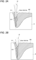
- the opening 811 of the keyhole 810 is expanded as compared with the case shown in FIG. 2A , so that the laser light LB more easily reaches the inside of the keyhole 810.
- the focal position of the laser light LB is moved inside the workpiece W from the surface thereof, since the laser light LB is converged in the vicinity of the opening 811 of the keyhole 810 and enters the inside of the keyhole 810, the laser light LB is less likely to be reflected by the keyhole wall in the vicinity of the entrance of the keyhole 810, and the light amount absorbed by the molten pool 800 increases, which also leads to an increase in the welding penetration depth.
- the welding penetration depth of the workpiece W reduces as the focal position of the laser light LB moves upward, that is, toward an outside of the workpiece W.
- the welding penetration depth of the workpiece W increases as the focal position of the laser light LB moves downward, that is, to a predetermined position inside the workpiece W.
- the focal position of the laser light LB is moved from the surface of the workpiece W to a predetermined position inside the workpiece W, and thus the welding penetration depth of the workpiece W can be increased.
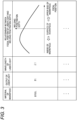
- a shape of a curve shown in FIG. 3 changes depending on the material of the workpiece W and an output of the laser light LB. Therefore, in the storage unit 72, the welding penetration depth of the workpiece W with respect to the focal position of the laser light LB is stored as data in a table format in association with the material of the workpiece W, the output of the laser light LB, and the wavelength of the laser light LB.
- the change of the welding penetration depth of the workpiece W with respect to the focal position of the laser light LB is shown in a graph format, but in practice, each plot of the curve shown in FIG. 3 is associated with the material of the workpiece W or the like in a data format.
- the focal position of the laser light LB is changed based on a shape of the welding portion of the workpiece W and the data shown in FIG. 3 , thus the laser welding can be appropriately performed according to the shape of the welding portion, and the joining strength of the workpiece W can be secured.
- the control unit 71 controls an output intensity (power density) of the laser light LB of the laser oscillator 80 according to the laser welding program stored in the storage unit 72.
- the control unit 71 transmits a position command to a servo motor (not shown) provided in the manipulator 60 according to the laser welding program stored in the storage unit 72 and a feedback signal from an encoder (not shown) provided in the manipulator 60, and controls a rotation speed and a rotation amount of the servo motor (not shown).
- the control unit 71 controls operations of the laser oscillator 80 and the welding head 30 based on an output signal (to be described later) obtained from the welding state detection mechanism 40. Details of operations of the control unit 71 will be described later.
- the display unit 73 displays an output state of the laser oscillator 80, an operation state of the manipulator 60, a warning, and the like under the control of the control unit 71.
- the manipulator 60 has a configuration in which the servo motor (not shown) and the encoder (not shown) are provided for each joint shaft (for example, four joint shafts are provided in FIG. 1 , but six shafts are often provided in the case of laser welding).
- the manipulator 60 is connected to the controller 70, and moves the welding head 30 so as to draw a predetermined trajectory according to the laser welding program described above by operating the servo motor and the encoder for each joint shaft.
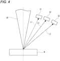
- FIG. 4 is a diagram schematically showing an example of arrangement positions of the first optical sensor S1, the second optical sensor S2, and the third optical sensor S3 constituting the welding state detection mechanism 40.
- the first optical sensor S1, the second optical sensor S2, and the third optical sensor S3 constituting the welding state detection mechanism 40 may be appropriately disposed on a lateral side (side surface) of the welding head 30 so as not to be coaxial with the laser light LB (in other words, laser beam) emitted to the workpiece W.
- the first optical sensor S1, the second optical sensor S2, and the third optical sensor S3 move in conjunction with the movement of the welding head 30.
- the first optical sensor S1, the second optical sensor S2, and the third optical sensor S3 may be appropriately disposed along the housing of the welding head 30.
- the first optical sensor S1 detects a light amount (an example of a sensor signal intensity) of specific wavelength light reflected from the welding point of the workpiece W when the workpiece W is irradiated with the laser light LB from the welding head 30 (that is, laser welding).
- the specific wavelength light has the same wavelength as the laser light LB (in other words, laser beam) emitted to the workpiece W.
- the specific wavelength light is referred to as reflected light L1.
- the second optical sensor S2 detects a light amount (an example of the sensor signal intensity) of plasma emission light L2 (for example, light having a wavelength in a visible light region) generated by irradiating the workpiece W with the laser light LB from the welding head 30 (that is, laser welding).
- a light amount an example of the sensor signal intensity
- plasma emission light L2 for example, light having a wavelength in a visible light region
- the third optical sensor S3 detects a light amount (an example of the sensor signal intensity) of radiated light generated by a temperature rise at the welding point of the workpiece W when the workpiece W is irradiated with the laser light LB from the welding head 30 (that is, laser welding), particularly, near-infrared light L3 (light having a wavelength of 800 nm or more, for example).
- FIG. 5A is a diagram showing an example of a distribution of sensor signal intensities obtained by the first optical sensor S1 when laser welding is normal.
- FIG. 5B is a diagram showing an example of a distribution of sensor signal intensities obtained by the first optical sensor S1 when laser welding is abnormal.
- a horizontal axis represents time
- a vertical axis represents the sensor signal intensity (that is, the light amount of the reflected light L1 (see the above description) detected by the first optical sensor S1).
- the first optical sensor S1 detects the reflected light L1 generated from the welding point in the laser welding.
- FIG. 5A shows a distribution characteristic (for example, a center curve MD1) of the light amount detected by the first optical sensor S1 when normal laser welding is performed from a start time point to an end time point of the laser welding, and shows that the sensor signal intensities have values in a normal range from a lower limit curve LW1 to an upper limit curve UP1.
- the workpiece W is a metal, and is in a solid state until the workpiece W starts to melt at the start time point of the laser welding. Therefore, at the start time point of the laser welding, reflectivity of the workpiece W tends to be high, and the sensor signal intensity tends to be relatively high. As the workpiece W begins to melt, the keyhole is formed and the reflectivity from the welding point gradually decreases, so that the sensor signal intensity gradually decreases from the initial high value and remains stable.
- a distribution characteristic MS1 of the light amount detected by the first optical sensor S1 has a value deviated from a range from the lower limit curve LW1 to the upper limit curve UP1 which is the normal range, such as a part A and a part B.
- the welding state detection mechanism 40 detects a welding defect (welding failure) of the corresponding welding point as a detection result of the first optical sensor S1.
- the sensor signal intensity is further decreased form the lower limit curve LW1.
- a variation in laser power or an individual variation in the workpiece W causes a variation in the molten pool in laser welding of a thin plate, and a hole is finally formed in the workpiece W, so that the sensor signal intensity of the reflected light L1 at the welding point is decreased from the lower limit curve LW1.
- the gap between an upper plate and a lower plate is too wide and the molten pool also increases, so that the reflected light L1 may decrease.
- the sensor signal intensity is further increased from the upper limit curve UP1. This is considered to be because an amount of melting of the workpiece W is not sufficient due to a variation of the laser power in the laser welding, so that the sensor signal intensity of the reflected light L1 at the welding point is increased form the upper limit curve UP1.
- FIG. 6A is a diagram showing an example of a distribution of sensor signal intensities obtained by the second optical sensor S2 when laser welding is normal.
- FIG. 6B is a diagram showing an example of a distribution of sensor signal intensities obtained by the second optical sensor S2 when laser welding is abnormal.
- a horizontal axis represents time
- a vertical axis represents a sensor signal intensity (that is, the light amount of the plasma emission light L2 (see the above description) detected by the second optical sensor S2).
- the second optical sensor S2 detects the plasma emission light L2 generated from the welding point in the laser welding.
- FIG. 6A shows a distribution characteristic (for example, a center curve MD2) of the light amount detected by the second optical sensor S2 when normal laser welding is performed from a start time point to an end time point of the laser welding, and shows that the sensor signal intensities have values in a normal range from a lower limit curve LW2 to an upper limit curve UP2.
- the plasma emission light L2 transitions substantially stably from the start time point to the end time point of the laser welding.
- a distribution characteristic MS2 of the light amount detected by the second optical sensor S2 has a value deviated from a range from the lower limit curve LW2 to the upper limit curve UP2 which is the normal range, such as a part C and a part D.
- the welding state detection mechanism 40 detects a welding defect (welding failure) of the corresponding welding point as a detection result of the second optical sensor S2.
- the sensor signal intensity is further increased from the upper limit curve UP2. This is considered to be because a phenomenon occurs in which the workpiece W is melted by a large amount and spatter is generated due to a variation in laser power of the laser welding or an individual variation of the workpiece W, a light amount of the plasma emission light at the welding point is temporarily increased from the upper limit curve UP2. Even if there is no variation in the laser power, when the keyhole greatly fluctuates due to the variation in the molten pool, large plasma emission light may be accompanied.
- the sensor signal intensity is further decreased from the lower limit curve LW2.
- the part D the sensor signal intensity is further decreased from the lower limit curve LW2.
- a hole is formed in the workpiece W due to a variation in molten pool during the laser welding, or a stable molten pool cannot be formed due to an excessively large gap, so that a light amount of the plasma emission light at the welding point is decreased from the lower limit curve LW2.
- FIG. 7A is a diagram showing an example of a distribution of sensor signal intensities obtained by the third optical sensor S3 when laser welding is normal.
- FIG. 7B is a diagram showing an example of a distribution of sensor signal intensities obtained by the third optical sensor S3 when laser welding is abnormal.
- a horizontal axis represents time
- a vertical axis represents the sensor signal intensity (that is, the light amount of the near-infrared light L3 (see the above description) detected by the third optical sensor S3).
- the third optical sensor S3 detects the near-infrared light L3 generated from the welding point and having a strong relationship with a temperature of the molten pool during the laser welding.
- FIG. 7A shows a distribution characteristic (for example, a center curve MD3) of the light amount detected by the third optical sensor S3 when the normal laser welding is performed from a start time point to an end time point of the laser welding, and shows that the sensor signal intensities have values in a normal range from a lower limit curve LW3 to an upper limit curve UP3.
- the workpiece W is a metal, and is in a solid state until the workpiece W starts to melt at the start time point of the laser welding. Therefore, since a temperature of the workpiece W is low at the start time point of the laser welding, a temperature of the molten pool is also relatively low, and the sensor signal intensity tends to be relatively low.
- the temperature of the workpiece W gradually increases and becomes stable, so that the near-infrared light L3 gradually increases toward the end time point of the laser welding.
- an intensity of the near-infrared light L3 increases gradually toward the welding end point, but depending on a combination of the workpiece W and the welding conditions, the intensity of the near-infrared light L3 may be substantially constant up to the welding end point.
- the distribution characteristic MS3 of the light amount detected by the third optical sensor S3 has a value deviated from the normal range such as a part E and a part F.
- the welding state detection mechanism 40 detects a welding defect (welding failure) of the corresponding welding point as a detection result of the third optical sensor S3.
- the sensor signal intensity is further increased from the upper limit curve UP3.
- the near-infrared light in other words, the temperature
- the sensor signal intensity is further decreased from the lower limit curve LW3.
- the sensor signal intensity is further decreased from the lower limit curve LW3. This is considered to be because, similarly to FIG. 6B , for example, a hole is formed in the workpiece W during the laser welding or a gap is large and the molten pool is deeply recessed, a light amount of the near-infrared light at the welding point is decreased from the lower limit curve LW3.
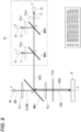
- FIG. 8 is a diagram schematically showing a second example of the arrangement positions of the first optical sensor S1, the second optical sensor S2, and the third optical sensor S3 constituting the welding state detection mechanism 40.
- the first optical sensor S1, the second optical sensor S2, and the third optical sensor S3 are all incorporated in the welding head 30.
- the welding head 30 is connected to the emission end of the optical fiber 90. Inside the welding head 30 shown in FIG.
- a collimating lens CLL1, a first mirror MRR1, a condenser lens FCL1, a protective glass PTG1, a second mirror MRR2, a condenser lens FCL2, the first optical sensor S1, a third mirror MRR3, a condenser lens FCL3, the second optical sensor S2, a condenser lens FCL4, and the third optical sensor S3 are disposed.
- the collimating lens CLL1, the first mirror MRR1, the condenser lens FCL1, and the protective glass PTG1 are disposed on an incidence light optical axis aa'.
- the first mirror MRR1, the condenser lens FCL1, and the protective glass PTG1 are also disposed on a reflected light optical axis a'b.
- the first mirror MRR1, the second mirror MRR2, the third mirror MRR3, and the condenser lens FCL4 are disposed on a reflected light optical axis bb'.
- the second mirror MRR2, the condenser lens FCL2, and the first optical sensor S1 are disposed on a reflected light optical axis cc'. c is located on the reflected light optical axis bb'.
- the third mirror MRR3, the condenser lens FCL3, and the second optical sensor S2 are disposed on a reflected light optical axis dd'. d is located on the reflected light optical axis b
- the laser light LB that is, an emission beam BM1
- the laser light LB travels along the incidence light optical axis aa', and is formed into a collimated beam CLLBM1 parallel to the incidence light optical axis aa' via the collimating lens CLL1.
- the collimated beam CLLBM1 passes through the first mirror MRR1 along the incidence light optical axis aa' and is condensed by the condenser lens FCL1.
- a condensed incidence beam ICB1 is emitted to the welding point of the workpiece W along the incidence light optical axis aa' via the protective glass PTG1.
- the first mirror MRR1 is coated in advance to transmit light in a direction of the incidence light optical axis aa' and to reflect light in a direction of the reflected light optical axis a'b clockwise by about 90 degrees in the figure.
- the light including various wavelength bands (for example, the reflected light L1, the plasma emission light L2, and the near-infrared light L3) generated from the welding point of the workpiece W travels along the reflected light optical axis a'b as a reflected beam RFB1, passes through the protective glass PTG1 and the condenser lens FCL1, and is reflected by the first mirror MRR1.
- various wavelength bands for example, the reflected light L1, the plasma emission light L2, and the near-infrared light L3
- the reflected beam RFB1 travels along the reflected light optical axis bb'.
- the reflected light L1 in the reflected beam RFB1 is reflected by the second mirror MRR2, and the remaining wavelength band light (specifically, the plasma emission light L2 and the near-infrared light L3) is transmitted through the second mirror MRR2.
- the second mirror MRR2 is coated in advance to reflect the reflected light L1 and to transmit the remaining wavelength band light (specifically, the plasma emission light L2 and the near-infrared light L3).
- the reflected light L1 travels along the reflected light optical axis cc', is condensed via the condenser lens FCL2, is received by the first optical sensor S1, and the light amount thereof is detected as the sensor signal intensity (see FIG. 5A or 5B ).
- the plasma emission light L2 and the near-infrared light L3 transmitted through the second mirror MRR2 the plasma emission light L2 is reflected by the third mirror MRR3, and the remaining wavelength band light (specifically, the near-infrared light L3) is transmitted through the third mirror MRR3.
- the third mirror MRR3 is coated in advance to reflect the plasma emission light L2 and transmit the remaining wavelength band light (specifically, the near-infrared light L3).
- the plasma emission light L2 travels along the reflected light optical axis dd', is condensed via the condenser lens FCL3, is received by the second optical sensor S2, and the light amount thereof is detected as the sensor signal intensity (see FIG. 6A or FIG. 6B ).
- the near-infrared light L3 transmitted through the third mirror MRR3 is condensed via the condenser lens FCL4 and received by the third optical sensor S3, and the light amount thereof is detected as the sensor signal intensity (see FIG. 7A or 7B ).
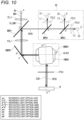
- FIG. 9 is a diagram schematically showing a third example of the arrangement positions of the first optical sensor S1, the second optical sensor S2, and the third optical sensor S3 constituting the welding state detection mechanism 40.
- the first optical sensor S1, the second optical sensor S2, and the third optical sensor S3 are all incorporated in the welding head 30.
- the same elements as those in FIG. 8 are denoted by the same reference numerals, the description thereof will be simplified or omitted, and different contents will be described.
- the collimating lens CLL1, the first mirror MRR1, a bend mirror BMRR1, a galvano scanner mechanism GLVU1, the condenser lens FCL1, the protective glass PTG1, the second mirror MRR2, the condenser lens FCL2, the first optical sensor S1, the third mirror MRR3, the condenser lens FCL3, the second optical sensor S2, the condenser lens FCL4, and the third optical sensor S3 are disposed.
- a configuration of the welding state detection mechanism 40 shown in FIG. 9 is the same as the configuration of the welding state detection mechanism 40 shown in FIG. 8 , and thus the description thereof will be omitted.
- FIG. 9 is different from FIG. 8 in that the galvano scanner mechanism GLVU1 is employed in FIG. 9 .
- the galvano scanner mechanism GLVU1 includes an X-axis mirror XMRR1 that is driven in an X-axis direction that defines any one of XY planes parallel to the surface of the workpiece W, a Y-axis mirror YMRR1 that is driven in a Y-axis direction that defines any one of the XY planes parallel to the surface of the workpiece W, and a control driver (not shown) that controls the X-axis mirror XMRR1 and the Y-axis mirror YMRR1.
- the galvano scanner mechanism GLVU1 controls the X-axis mirror XMRR1 and the Y-axis mirror YMRR1 to emit the light incident on the galvano scanner mechanism GLVU1 (specifically, the collimated beam CLLBM1 reflected by the bend mirror BMRR1) to the welding point of the workpiece W as the incidence beam ICB1.
Landscapes
- Engineering & Computer Science (AREA)
- Physics & Mathematics (AREA)
- Optics & Photonics (AREA)
- Mechanical Engineering (AREA)
- Plasma & Fusion (AREA)
- Quality & Reliability (AREA)
- Laser Beam Processing (AREA)
Claims (9)
- Laserschweißvorrichtung, umfassend:einen Laseroszillator, mit dem ein Einfallsende einer Faser verbunden ist;einen Schweißkopf, der mit einem Emissionsende der Faser verbunden ist und dazu ausgestaltet ist, Laserschweißen bei gleichzeitigem Kondensieren von Laserlicht, das von dem Laseroszillator über das Emissionsende emittiert wird, und Bestrahlen eines Werkstücks mit dem Laserlicht durchzuführen;eine Detektionseinheit, die dazu ausgestaltet ist, Vorhandensein oder Nichtvorhandensein eines Defekts in dem Laserschweißen zu detektieren; undeine Steuereinrichtung, die dazu ausgestaltet ist, Arbeitsvorgänge des Laseroszillators und des Schweißkopfs basierend auf einem Ausgabesignal der Detektionseinheit zu steuern,wobei die Laserschweißvorrichtung dadurch gekennzeichnet ist, dassbeim Empfangen eines Ausgabesignals, das einen Defekt an einer ersten Schweißstelle auf dem Werkstück angibt, von der Detektionseinheit während des Laserschweißens des Werkstücks die Steuereinrichtung Steuerung derart durchführt, dass eine zusätzliche Laserschweißstelle an einer vorbestimmten Position in einer Nachbarschaft der ersten Schweißstelle durchgeführt wird.
- Laserschweißvorrichtung nach Anspruch 1,
wobei die Steuereinrichtung Steuerung derart durchführt, dass, nachdem die zusätzliche Laserschweißstelle durchgeführt wurde, Laserschweißen an einer zweiten Schweißstelle durchgeführt wird, die eine nächste Schweißstelle angibt, die auf die erste Schweißstelle folgt. - Laserschweißvorrichtung nach Anspruch 1,
wobei die Detektionseinheit eine Vielzahl von verschiedenen Sensoren umfasst, wobei die Detektionseinheit dazu ausgestaltet ist, ein Ausgabesignal auszugeben, das angibt, dass ein Defekt in dem Laserschweißen vorliegt, wenn ein Signal, das eine Anomalie angibt, von mindestens einem der Sensoren empfangen wird. - Laserschweißvorrichtung nach Anspruch 3,
wobei die Detektionseinheit umfasst:einen ersten optischen Sensor, der dazu ausgestaltet ist, Licht mit spezifischer Wellenlänge von der Schweißstelle zu empfangen, die von dem Laserschweißen erzeugt wird, und das Vorhandensein oder Nichtvorhandensein der Anomalie basierend auf einer Stärke der spezifischen Wellenlänge zu detektieren;einen zweiten optischen Sensor, der dazu ausgestaltet ist, Plasmaemissionslicht von der Schweißstelle zu empfangen, die von dem Laserschweißen erzeugt wird, und das Vorhandensein oder Nichtvorhandensein der Anomalie basierend auf einer Stärke des Plasmaemissionslichts zu detektieren; undeinen dritten optischen Sensor, der dazu ausgestaltet ist, Nahinfrarotlicht von der Schweißstelle zu empfangen, die von dem Laserschweißen erzeugt wird, und das Vorhandensein oder Nichtvorhandensein der Anomalie basierend auf einer Stärke des Nahinfrarotlichts zu detektieren. - Laserschweißvorrichtung nach Anspruch 4,wobei der erste optische Sensor reflektiertes Licht von der Schweißstelle als das Licht mit der spezifischen Wellenlänge empfängt,wobei der zweite optische Sensor Licht, das eine Wellenlänge von 400 nm bis 800 nm unter dem Plasmaemissionslicht aufweist, empfängt, undwobei der dritte optische Sensor Licht, das eine Wellenlänge von 800 nm bis 2000 nm unter dem Nahinfrarotlicht aufweist, empfängt.
- Laserschweißvorrichtung nach Anspruch 3,
wobei jeder der Vielzahl von verschiedenen Sensoren in der Nachbarschaft des Schweißkopfs angeordnet ist. - Laserschweißvorrichtung nach Anspruch 3,
wobei jeder der Vielzahl von verschiedenen Sensoren in dem Schweißkopf koaxial mit einer Emissionsrichtung des Laserlichts zu dem Werkstück angeordnet ist. - Laserschweißvorrichtung nach Anspruch 3,wobei jeder der Vielzahl von verschiedenen Sensoren in dem Schweißkopf angeordnet ist, undwobei der Schweißkopf einen Galvo-Scanner-Mechanismus umfasst, der dazu ausgestaltet ist, das Laserlicht zur Schweißstelle des Werkstücks zu emittieren.
- Laserschweißverfahren, umfassend:einen Schritt des Durchführens von Laserschweißen bei gleichzeitigem Kondensieren von Laserlicht, das von einem Laseroszillator, mit dem ein Einfallsende einer Faser verbunden ist, über ein Emissionsende der Faser emittiert wird, und Bestrahlen eines Werkstücks mit dem kondensierten Laserlicht;einen Schritt des Detektierens von Vorhandensein oder Nichtvorhandensein eines Defekts in dem Laserschweißen;einen Schritt des Steuerns von Arbeitsvorgängen des Laseroszillators und eines Schweißkopfs basierend auf einem Ausgabesignal einer Detektionseinheit, die dazu ausgestaltet ist, das Vorhandensein oder Nichtvorhandensein eines Defekts in dem Laserschweißen zu detektieren;wobei das Verfahren gekennzeichnet ist durch:
einen Schritt des Ausführens, beim Empfangen eines Ausgabesignals, das einen Defekt an einer Schweißstelle auf dem Werkstück während des Laserschweißens des Werkstücks angibt, von zusätzlichem Laserschweißen an einer vorbestimmten Position in einer Nachbarschaft der Schweißstelle.
Applications Claiming Priority (2)
| Application Number | Priority Date | Filing Date | Title |
|---|---|---|---|
| JP2020111720 | 2020-06-29 | ||
| PCT/JP2021/024223 WO2022004610A1 (ja) | 2020-06-29 | 2021-06-25 | レーザ溶接装置およびレーザ溶接方法 |
Publications (3)
| Publication Number | Publication Date |
|---|---|
| EP4173749A1 EP4173749A1 (de) | 2023-05-03 |
| EP4173749A4 EP4173749A4 (de) | 2024-01-31 |
| EP4173749B1 true EP4173749B1 (de) | 2025-03-12 |
Family
ID=79316061
Family Applications (1)
| Application Number | Title | Priority Date | Filing Date |
|---|---|---|---|
| EP21833793.9A Active EP4173749B1 (de) | 2020-06-29 | 2021-06-25 | Laserschweissvorrichtung und laserschweissverfahren |
Country Status (4)
| Country | Link |
|---|---|
| US (1) | US20230121254A1 (de) |
| EP (1) | EP4173749B1 (de) |
| JP (1) | JP7696107B2 (de) |
| WO (1) | WO2022004610A1 (de) |
Families Citing this family (5)
| Publication number | Priority date | Publication date | Assignee | Title |
|---|---|---|---|---|
| EP4292749A1 (de) * | 2022-06-15 | 2023-12-20 | Fritz Stepper GmbH & Co. KG | Laser-schweissvorrichtung und verfahren zur überwachung, mit einem laser-schweisskopf und einer überwachungseinrichtung |
| EP4321291B1 (de) * | 2022-07-27 | 2026-03-04 | Fritz Stepper GmbH & Co. KG | Laser-schweissvorrichtung und verfahren zur überwachung, mit einem laser-schweisskopf und einer überwachungseinrichtung |
| DE102023103439A1 (de) * | 2023-02-13 | 2024-08-14 | TRUMPF Laser- und Systemtechnik SE | Computergestütztes Verfahren |
| WO2024224874A1 (ja) * | 2023-04-25 | 2024-10-31 | パナソニックIpマネジメント株式会社 | 溶接状態の検出方法及び検出装置 |
| DE102023004005A1 (de) * | 2023-10-06 | 2024-09-26 | Mercedes-Benz Group AG | Laserschweißvorrichtung und Laserschweißverfahren |
Family Cites Families (14)
| Publication number | Priority date | Publication date | Assignee | Title |
|---|---|---|---|---|
| JPH03169494A (ja) * | 1989-11-28 | 1991-07-23 | Toshiba Corp | 部材の溶接補修方法および部材の溶接補修装置 |
| JPH0747471A (ja) * | 1993-08-09 | 1995-02-21 | Ishikawajima Harima Heavy Ind Co Ltd | 溶接品質診断保証装置 |
| JPH1015677A (ja) * | 1996-07-02 | 1998-01-20 | Hitachi Ltd | 溶接構造物に対する加熱再溶融方法、およびそれに用いる装置 |
| JP4432282B2 (ja) * | 2001-05-29 | 2010-03-17 | 株式会社デンソー | レーザ溶接品質判定方法 |
| JP3792683B2 (ja) * | 2003-07-16 | 2006-07-05 | ファナック株式会社 | レーザ溶接装置 |
| JP4617324B2 (ja) * | 2007-01-31 | 2011-01-26 | 東急車輛製造株式会社 | レーザ溶接部形成方法 |
| US8552337B2 (en) * | 2009-06-11 | 2013-10-08 | Illinois Tool Works Inc. | Weld defect detection systems and methods for laser hybrid welding |
| JP2012148316A (ja) * | 2011-01-19 | 2012-08-09 | Keyence Corp | レーザー加工装置 |
| JP5947740B2 (ja) * | 2013-03-29 | 2016-07-06 | トヨタ自動車株式会社 | 溶接部の検査装置とその検査方法 |
| WO2016032416A1 (en) | 2014-08-25 | 2016-03-03 | GM Global Technology Operations LLC | Laser welding metal workpieces |
| JP2017177222A (ja) * | 2016-03-28 | 2017-10-05 | パナソニックIpマネジメント株式会社 | レーザ溶接方法およびレーザ溶接装置 |
| JP7312628B2 (ja) | 2019-01-07 | 2023-07-21 | 住友ベークライト株式会社 | ゴム組成物、およびゴム製品 |
| DE102020104462A1 (de) * | 2020-02-20 | 2021-08-26 | Precitec Gmbh & Co. Kg | Verfahren zum Analysieren einer Schweißverbindung beim Laserschweißen von Werkstücken |
| JP7326617B2 (ja) * | 2020-06-25 | 2023-08-15 | 古河電気工業株式会社 | バスバーおよびバスバーの製造方法 |
-
2021
- 2021-06-25 WO PCT/JP2021/024223 patent/WO2022004610A1/ja not_active Ceased
- 2021-06-25 EP EP21833793.9A patent/EP4173749B1/de active Active
- 2021-06-25 JP JP2022533966A patent/JP7696107B2/ja active Active
-
2022
- 2022-12-20 US US18/084,813 patent/US20230121254A1/en active Pending
Also Published As
| Publication number | Publication date |
|---|---|
| JPWO2022004610A1 (de) | 2022-01-06 |
| US20230121254A1 (en) | 2023-04-20 |
| EP4173749A4 (de) | 2024-01-31 |
| EP4173749A1 (de) | 2023-05-03 |
| JP7696107B2 (ja) | 2025-06-20 |
| WO2022004610A1 (ja) | 2022-01-06 |
Similar Documents
| Publication | Publication Date | Title |
|---|---|---|
| EP4173749B1 (de) | Laserschweissvorrichtung und laserschweissverfahren | |
| US12296405B2 (en) | Laser welding device with changing focal position and laser welding method using same | |
| US20170282294A1 (en) | Laser build-up method | |
| EP3978183B1 (de) | Laserbearbeitungsvorrichtung und laserbearbeitungsverfahren damit | |
| CN113814564B (zh) | 激光焊接方法以及装置 | |
| US12544858B2 (en) | Laser welding method and laser welding device | |
| JP2024539128A (ja) | レーザ指向変化時に経路偏差を補正する方法及びその装置並びに工作機械 | |
| US20130170515A1 (en) | Laser processing apparatus and laser processing method | |
| US12263540B2 (en) | Laser processing device and laser processing method using same | |
| EP3766630B1 (de) | Laserbearbeitungsmaschine und laserbearbeitungsverfahren | |
| EP3404404A1 (de) | Verfahren zur erkennung eines loches in einem lasergeschweissten teil und laserschweissvorrichtung | |
| JP6780544B2 (ja) | レーザ溶接装置 | |
| JP2013226590A (ja) | レーザ切断装置及びレーザ切断方法 | |
| KR20100069609A (ko) | 밀봉 장치, 밀봉 방법 및 평판 디스플레이의 제조 방법 | |
| JP7713645B2 (ja) | レーザ溶接装置及びレーザ光の照射位置ずれの補正方法 | |
| JP2017131955A (ja) | 加工ヘッドのアプローチ機能を有するレーザ加工機 | |
| JP7620795B2 (ja) | レーザ加工装置 | |
| EP4163045A1 (de) | Laserschweissvorrichtung und laserschweissverfahren | |
| US20250326060A1 (en) | Laser welding method for stacked metal foils | |
| WO2023157883A1 (ja) | レーザ溶接装置及びレーザ光の照射位置ずれの補正方法 | |
| KR20090032222A (ko) | 반사경을 이용한 레이져 용접 시스템 및 그 용접방법 | |
| JP2023112740A (ja) | レーザ装置及びこれを備えたレーザ加工装置 | |
| JP2023112735A (ja) | レーザ溶接方法 | |
| CN121568806A (zh) | 激光焊接装置以及焦点移位探测方法 | |
| JPH06246466A (ja) | レーザ加工方法 |
Legal Events
| Date | Code | Title | Description |
|---|---|---|---|
| STAA | Information on the status of an ep patent application or granted ep patent |
Free format text: STATUS: THE INTERNATIONAL PUBLICATION HAS BEEN MADE |
|
| PUAI | Public reference made under article 153(3) epc to a published international application that has entered the european phase |
Free format text: ORIGINAL CODE: 0009012 |
|
| STAA | Information on the status of an ep patent application or granted ep patent |
Free format text: STATUS: REQUEST FOR EXAMINATION WAS MADE |
|
| 17P | Request for examination filed |
Effective date: 20221215 |
|
| AK | Designated contracting states |
Kind code of ref document: A1 Designated state(s): AL AT BE BG CH CY CZ DE DK EE ES FI FR GB GR HR HU IE IS IT LI LT LU LV MC MK MT NL NO PL PT RO RS SE SI SK SM TR |
|
| DAV | Request for validation of the european patent (deleted) | ||
| DAX | Request for extension of the european patent (deleted) | ||
| A4 | Supplementary search report drawn up and despatched |
Effective date: 20240105 |
|
| RIC1 | Information provided on ipc code assigned before grant |
Ipc: B23K 26/082 20140101ALI20231222BHEP Ipc: B23K 31/12 20060101ALI20231222BHEP Ipc: B23K 26/06 20140101ALI20231222BHEP Ipc: B23K 26/03 20060101ALI20231222BHEP Ipc: B23K 26/21 20140101ALI20231222BHEP Ipc: B23K 26/00 20140101AFI20231222BHEP |
|
| GRAP | Despatch of communication of intention to grant a patent |
Free format text: ORIGINAL CODE: EPIDOSNIGR1 |
|
| STAA | Information on the status of an ep patent application or granted ep patent |
Free format text: STATUS: GRANT OF PATENT IS INTENDED |
|
| RIC1 | Information provided on ipc code assigned before grant |
Ipc: B23K 26/22 20060101ALI20240923BHEP Ipc: B23K 26/082 20140101ALI20240923BHEP Ipc: B23K 31/12 20060101ALI20240923BHEP Ipc: B23K 26/06 20140101ALI20240923BHEP Ipc: B23K 26/03 20060101ALI20240923BHEP Ipc: B23K 26/21 20140101ALI20240923BHEP Ipc: B23K 26/00 20140101AFI20240923BHEP |
|
| INTG | Intention to grant announced |
Effective date: 20241018 |
|
| GRAS | Grant fee paid |
Free format text: ORIGINAL CODE: EPIDOSNIGR3 |
|
| GRAA | (expected) grant |
Free format text: ORIGINAL CODE: 0009210 |
|
| STAA | Information on the status of an ep patent application or granted ep patent |
Free format text: STATUS: THE PATENT HAS BEEN GRANTED |
|
| AK | Designated contracting states |
Kind code of ref document: B1 Designated state(s): AL AT BE BG CH CY CZ DE DK EE ES FI FR GB GR HR HU IE IS IT LI LT LU LV MC MK MT NL NO PL PT RO RS SE SI SK SM TR |
|
| REG | Reference to a national code |
Ref country code: GB Ref legal event code: FG4D |
|
| REG | Reference to a national code |
Ref country code: CH Ref legal event code: EP |
|
| REG | Reference to a national code |
Ref country code: DE Ref legal event code: R096 Ref document number: 602021027610 Country of ref document: DE |
|
| REG | Reference to a national code |
Ref country code: IE Ref legal event code: FG4D |
|
| PG25 | Lapsed in a contracting state [announced via postgrant information from national office to epo] |
Ref country code: RS Free format text: LAPSE BECAUSE OF FAILURE TO SUBMIT A TRANSLATION OF THE DESCRIPTION OR TO PAY THE FEE WITHIN THE PRESCRIBED TIME-LIMIT Effective date: 20250612 |
|
| PG25 | Lapsed in a contracting state [announced via postgrant information from national office to epo] |
Ref country code: FI Free format text: LAPSE BECAUSE OF FAILURE TO SUBMIT A TRANSLATION OF THE DESCRIPTION OR TO PAY THE FEE WITHIN THE PRESCRIBED TIME-LIMIT Effective date: 20250312 |
|
| PGFP | Annual fee paid to national office [announced via postgrant information from national office to epo] |
Ref country code: DE Payment date: 20250618 Year of fee payment: 5 |
|
| PG25 | Lapsed in a contracting state [announced via postgrant information from national office to epo] |
Ref country code: ES Free format text: LAPSE BECAUSE OF FAILURE TO SUBMIT A TRANSLATION OF THE DESCRIPTION OR TO PAY THE FEE WITHIN THE PRESCRIBED TIME-LIMIT Effective date: 20250312 |
|
| REG | Reference to a national code |
Ref country code: LT Ref legal event code: MG9D |
|
| PG25 | Lapsed in a contracting state [announced via postgrant information from national office to epo] |
Ref country code: NO Free format text: LAPSE BECAUSE OF FAILURE TO SUBMIT A TRANSLATION OF THE DESCRIPTION OR TO PAY THE FEE WITHIN THE PRESCRIBED TIME-LIMIT Effective date: 20250612 |
|
| PG25 | Lapsed in a contracting state [announced via postgrant information from national office to epo] |
Ref country code: HR Free format text: LAPSE BECAUSE OF FAILURE TO SUBMIT A TRANSLATION OF THE DESCRIPTION OR TO PAY THE FEE WITHIN THE PRESCRIBED TIME-LIMIT Effective date: 20250312 |
|
| REG | Reference to a national code |
Ref country code: NL Ref legal event code: MP Effective date: 20250312 |
|
| PG25 | Lapsed in a contracting state [announced via postgrant information from national office to epo] |
Ref country code: LV Free format text: LAPSE BECAUSE OF FAILURE TO SUBMIT A TRANSLATION OF THE DESCRIPTION OR TO PAY THE FEE WITHIN THE PRESCRIBED TIME-LIMIT Effective date: 20250312 |
|
| PG25 | Lapsed in a contracting state [announced via postgrant information from national office to epo] |
Ref country code: BG Free format text: LAPSE BECAUSE OF FAILURE TO SUBMIT A TRANSLATION OF THE DESCRIPTION OR TO PAY THE FEE WITHIN THE PRESCRIBED TIME-LIMIT Effective date: 20250312 Ref country code: GR Free format text: LAPSE BECAUSE OF FAILURE TO SUBMIT A TRANSLATION OF THE DESCRIPTION OR TO PAY THE FEE WITHIN THE PRESCRIBED TIME-LIMIT Effective date: 20250613 |
|
| REG | Reference to a national code |
Ref country code: AT Ref legal event code: MK05 Ref document number: 1774612 Country of ref document: AT Kind code of ref document: T Effective date: 20250312 |
|
| PG25 | Lapsed in a contracting state [announced via postgrant information from national office to epo] |
Ref country code: NL Free format text: LAPSE BECAUSE OF FAILURE TO SUBMIT A TRANSLATION OF THE DESCRIPTION OR TO PAY THE FEE WITHIN THE PRESCRIBED TIME-LIMIT Effective date: 20250312 |
|
| PG25 | Lapsed in a contracting state [announced via postgrant information from national office to epo] |
Ref country code: SE Free format text: LAPSE BECAUSE OF FAILURE TO SUBMIT A TRANSLATION OF THE DESCRIPTION OR TO PAY THE FEE WITHIN THE PRESCRIBED TIME-LIMIT Effective date: 20250312 |
|
| PG25 | Lapsed in a contracting state [announced via postgrant information from national office to epo] |
Ref country code: SM Free format text: LAPSE BECAUSE OF FAILURE TO SUBMIT A TRANSLATION OF THE DESCRIPTION OR TO PAY THE FEE WITHIN THE PRESCRIBED TIME-LIMIT Effective date: 20250312 |
|
| PG25 | Lapsed in a contracting state [announced via postgrant information from national office to epo] |
Ref country code: PT Free format text: LAPSE BECAUSE OF FAILURE TO SUBMIT A TRANSLATION OF THE DESCRIPTION OR TO PAY THE FEE WITHIN THE PRESCRIBED TIME-LIMIT Effective date: 20250714 |
|
| PG25 | Lapsed in a contracting state [announced via postgrant information from national office to epo] |
Ref country code: IT Free format text: LAPSE BECAUSE OF FAILURE TO SUBMIT A TRANSLATION OF THE DESCRIPTION OR TO PAY THE FEE WITHIN THE PRESCRIBED TIME-LIMIT Effective date: 20250312 Ref country code: PL Free format text: LAPSE BECAUSE OF FAILURE TO SUBMIT A TRANSLATION OF THE DESCRIPTION OR TO PAY THE FEE WITHIN THE PRESCRIBED TIME-LIMIT Effective date: 20250312 |
|
| PG25 | Lapsed in a contracting state [announced via postgrant information from national office to epo] |
Ref country code: AT Free format text: LAPSE BECAUSE OF FAILURE TO SUBMIT A TRANSLATION OF THE DESCRIPTION OR TO PAY THE FEE WITHIN THE PRESCRIBED TIME-LIMIT Effective date: 20250312 |
|
| PG25 | Lapsed in a contracting state [announced via postgrant information from national office to epo] |
Ref country code: CZ Free format text: LAPSE BECAUSE OF FAILURE TO SUBMIT A TRANSLATION OF THE DESCRIPTION OR TO PAY THE FEE WITHIN THE PRESCRIBED TIME-LIMIT Effective date: 20250312 Ref country code: EE Free format text: LAPSE BECAUSE OF FAILURE TO SUBMIT A TRANSLATION OF THE DESCRIPTION OR TO PAY THE FEE WITHIN THE PRESCRIBED TIME-LIMIT Effective date: 20250312 |
|
| PG25 | Lapsed in a contracting state [announced via postgrant information from national office to epo] |
Ref country code: RO Free format text: LAPSE BECAUSE OF FAILURE TO SUBMIT A TRANSLATION OF THE DESCRIPTION OR TO PAY THE FEE WITHIN THE PRESCRIBED TIME-LIMIT Effective date: 20250312 |
|
| PG25 | Lapsed in a contracting state [announced via postgrant information from national office to epo] |
Ref country code: SK Free format text: LAPSE BECAUSE OF FAILURE TO SUBMIT A TRANSLATION OF THE DESCRIPTION OR TO PAY THE FEE WITHIN THE PRESCRIBED TIME-LIMIT Effective date: 20250312 |
|
| PG25 | Lapsed in a contracting state [announced via postgrant information from national office to epo] |
Ref country code: IS Free format text: LAPSE BECAUSE OF FAILURE TO SUBMIT A TRANSLATION OF THE DESCRIPTION OR TO PAY THE FEE WITHIN THE PRESCRIBED TIME-LIMIT Effective date: 20250712 |
|
| REG | Reference to a national code |
Ref country code: DE Ref legal event code: R097 Ref document number: 602021027610 Country of ref document: DE |
|
| PG25 | Lapsed in a contracting state [announced via postgrant information from national office to epo] |
Ref country code: DK Free format text: LAPSE BECAUSE OF FAILURE TO SUBMIT A TRANSLATION OF THE DESCRIPTION OR TO PAY THE FEE WITHIN THE PRESCRIBED TIME-LIMIT Effective date: 20250312 |
|
| PLBE | No opposition filed within time limit |
Free format text: ORIGINAL CODE: 0009261 |
|
| STAA | Information on the status of an ep patent application or granted ep patent |
Free format text: STATUS: NO OPPOSITION FILED WITHIN TIME LIMIT |
|
| REG | Reference to a national code |
Ref country code: CH Ref legal event code: L10 Free format text: ST27 STATUS EVENT CODE: U-0-0-L10-L00 (AS PROVIDED BY THE NATIONAL OFFICE) Effective date: 20260121 |
|
| REG | Reference to a national code |
Ref country code: CH Ref legal event code: H13 Free format text: ST27 STATUS EVENT CODE: U-0-0-H10-H13 (AS PROVIDED BY THE NATIONAL OFFICE) Effective date: 20260127 |
|
| PG25 | Lapsed in a contracting state [announced via postgrant information from national office to epo] |
Ref country code: MC Free format text: LAPSE BECAUSE OF FAILURE TO SUBMIT A TRANSLATION OF THE DESCRIPTION OR TO PAY THE FEE WITHIN THE PRESCRIBED TIME-LIMIT Effective date: 20250312 |
|
| PG25 | Lapsed in a contracting state [announced via postgrant information from national office to epo] |
Ref country code: LU Free format text: LAPSE BECAUSE OF NON-PAYMENT OF DUE FEES Effective date: 20250625 |
|
| 26N | No opposition filed |
Effective date: 20251215 |
|
| GBPC | Gb: european patent ceased through non-payment of renewal fee |
Effective date: 20250625 |
|
| REG | Reference to a national code |
Ref country code: BE Ref legal event code: MM Effective date: 20250630 |
|
| PG25 | Lapsed in a contracting state [announced via postgrant information from national office to epo] |
Ref country code: GB Free format text: LAPSE BECAUSE OF NON-PAYMENT OF DUE FEES Effective date: 20250625 |
|
| PG25 | Lapsed in a contracting state [announced via postgrant information from national office to epo] |
Ref country code: IE Free format text: LAPSE BECAUSE OF NON-PAYMENT OF DUE FEES Effective date: 20250625 |
|
| PG25 | Lapsed in a contracting state [announced via postgrant information from national office to epo] |
Ref country code: BE Free format text: LAPSE BECAUSE OF NON-PAYMENT OF DUE FEES Effective date: 20250630 |
|
| PG25 | Lapsed in a contracting state [announced via postgrant information from national office to epo] |
Ref country code: FR Free format text: LAPSE BECAUSE OF NON-PAYMENT OF DUE FEES Effective date: 20250630 |