EP4173469A1 - Tedder rotatif avec dispositif de levage - Google Patents
Tedder rotatif avec dispositif de levage Download PDFInfo
- Publication number
- EP4173469A1 EP4173469A1 EP21204838.3A EP21204838A EP4173469A1 EP 4173469 A1 EP4173469 A1 EP 4173469A1 EP 21204838 A EP21204838 A EP 21204838A EP 4173469 A1 EP4173469 A1 EP 4173469A1
- Authority
- EP
- European Patent Office
- Prior art keywords
- tedder
- frame
- implement
- wheel support
- actuator
- Prior art date
- Legal status (The legal status is an assumption and is not a legal conclusion. Google has not performed a legal analysis and makes no representation as to the accuracy of the status listed.)
- Pending
Links
- 230000000694 effects Effects 0.000 description 5
- 238000012423 maintenance Methods 0.000 description 2
- 238000010276 construction Methods 0.000 description 1
- 230000006378 damage Effects 0.000 description 1
- 230000003247 decreasing effect Effects 0.000 description 1
- 230000001419 dependent effect Effects 0.000 description 1
- 238000001514 detection method Methods 0.000 description 1
- 238000004519 manufacturing process Methods 0.000 description 1
- 239000000463 material Substances 0.000 description 1
- 230000000630 rising effect Effects 0.000 description 1
- 239000011435 rock Substances 0.000 description 1
- 239000004575 stone Substances 0.000 description 1
- 230000001960 triggered effect Effects 0.000 description 1
Images

Classifications
-
- A—HUMAN NECESSITIES
- A01—AGRICULTURE; FORESTRY; ANIMAL HUSBANDRY; HUNTING; TRAPPING; FISHING
- A01D—HARVESTING; MOWING
- A01D78/00—Haymakers with tines moving with respect to the machine
- A01D78/08—Haymakers with tines moving with respect to the machine with tine-carrying rotary heads or wheels
- A01D78/10—Haymakers with tines moving with respect to the machine with tine-carrying rotary heads or wheels the tines rotating about a substantially vertical axis
- A01D78/1007—Arrangements to facilitate transportation specially adapted therefor
- A01D78/1014—Folding frames
-
- A—HUMAN NECESSITIES
- A01—AGRICULTURE; FORESTRY; ANIMAL HUSBANDRY; HUNTING; TRAPPING; FISHING
- A01B—SOIL WORKING IN AGRICULTURE OR FORESTRY; PARTS, DETAILS, OR ACCESSORIES OF AGRICULTURAL MACHINES OR IMPLEMENTS, IN GENERAL
- A01B63/00—Lifting or adjusting devices or arrangements for agricultural machines or implements
- A01B63/14—Lifting or adjusting devices or arrangements for agricultural machines or implements for implements drawn by animals or tractors
- A01B63/16—Lifting or adjusting devices or arrangements for agricultural machines or implements for implements drawn by animals or tractors with wheels adjustable relatively to the frame
- A01B63/22—Lifting or adjusting devices or arrangements for agricultural machines or implements for implements drawn by animals or tractors with wheels adjustable relatively to the frame operated by hydraulic or pneumatic means
-
- A—HUMAN NECESSITIES
- A01—AGRICULTURE; FORESTRY; ANIMAL HUSBANDRY; HUNTING; TRAPPING; FISHING
- A01B—SOIL WORKING IN AGRICULTURE OR FORESTRY; PARTS, DETAILS, OR ACCESSORIES OF AGRICULTURAL MACHINES OR IMPLEMENTS, IN GENERAL
- A01B73/00—Means or arrangements to facilitate transportation of agricultural machines or implements, e.g. folding frames to reduce overall width
- A01B73/02—Folding frames
- A01B73/04—Folding frames foldable about a horizontal axis
- A01B73/044—Folding frames foldable about a horizontal axis the axis being oriented in a longitudinal direction
-
- A—HUMAN NECESSITIES
- A01—AGRICULTURE; FORESTRY; ANIMAL HUSBANDRY; HUNTING; TRAPPING; FISHING
- A01D—HARVESTING; MOWING
- A01D78/00—Haymakers with tines moving with respect to the machine
- A01D78/08—Haymakers with tines moving with respect to the machine with tine-carrying rotary heads or wheels
- A01D78/10—Haymakers with tines moving with respect to the machine with tine-carrying rotary heads or wheels the tines rotating about a substantially vertical axis
- A01D78/1028—Pivotable rotor support arms
Definitions
- the present invention relates to an agricultural implement, preferably a rotary tedder or hay-making machine for turning crops lying on an agricultural field.
- Agricultural implements of this type comprise a main frame attachable to a towing vehicle, a wheel support supporting the main frame and having a plurality of main wheels, a plurality of tedder units supported on a tedder frame, and a lifting unit configured for bringing the implement into one of a transport position, a working position and a headland position.
- Large haymaking machines with working widths of more than 10 meters usually comprise a plurality of rotary tedder units running in a parallel line which is transverse to a direction of travel of the towing vehicle.
- These rotary tedder units are supported on the tedder frame which is pivotably attached to the main frame in a fashion such that the tedder units may be lifted sufficiently above ground in a headland position such that the working direction of the towing vehicle may be altered.
- the tedder frame including the rotary tedder units may further be lifted and/or folded onto the main frame when in a transport position for road transport. In some countries the dimensions of an agricultural implement in road transport position must not significantly exceed a width of 3 m and a height of 4 m.
- the tedder frame is regularly divided into several sections of predetermined width which are hingedly connected with each other along a horizontal pivot axis extending substantially in the direction of travel.
- EP 2 499 897 A1 discloses a haymaking machine having a main frame supported on a chassis, a plurality of haymaking units supported at a support frame and a lifting apparatus configured to lift the support frame together with the haymaking units relative to the main frame into a working position, a headland position and a travel position. This is achieved by providing an intermediate frame provided between the main frame and the support frame, the intermediate frame being pivotally connected to the main frame about a first horizontal transverse axle and being pivotally connected to the support frame about a second horizontal transverse axle.
- the structure of the haymaking machine in EP 2 499 897 A1 is rather complex from a mechanical point of view and requires relatively high maintenance and handling effort.
- the object of the present invention to provide an agricultural implement, preferably a tedder, which improves at least some of the shortcomings of the prior art.
- the improved agricultural implement shall provide a simple structure and a reliable function when changing from the working position, the headland position and the transport/travel position into any of the remaining positions. Further, an unwanted touching of the ground surface by the tines and thus an undesirable destruction of the ground and the used material shall be avoided.
- an agricultural implement preferably a tedder, comprises a main frame attachable to a towing vehicle, a wheel support supporting the main frame and having a plurality of main wheels, a plurality of tedder units supported on a tedder frame, a lifting unit configured for bringing the implement into one of a transport position, a working position and a headland position, wherein the wheel support and the tedder frame are separate elements, each pivotable around the common axle on the main frame, wherein the lifting unit comprises at least one adjustment actuator and is attached to the wheel support at a first attachment point and to the tedder frame at a second attachment point, the lifting unit thereby bridging the common axle, wherein the lifting unit comprises guiding means on the tedder frame, and wherein the lifting unit is configured to pivot the tedder frame and the wheel support around the common axle thereby bringing the implement into a predetermined position between the working position and the headland position.
- This simple structure is relatively easy to assemble and to maintain and offers a reliable function of the agricultural implement.
- the predetermined position between and including the working position and the headland position may include a position in which tines of the tedder unit are lifted above ground and tedder wheels of the tedder unit remain on ground. In this predetermined position, the tines of each tedder unit have been lifted so that their distance to the ground surface is sufficient for not destroying the surface and for not damaging the tines. It is noted that this predetermined position may achieved by minimally actuating the components of the lifting unit, i.e. by avoiding that any major hydraulic components of the agricultural implement except the components of the lifting unit are actuated. It should also be noted that the predetermined position can also be the working position or the headland position, i.e. that both end positions are included in the range.
- the tedder frame comprises a guiding portion having a long hole as guiding means.
- the long hole as part of the guiding means on the tedder frame is easy to manufacture, to maintain and to monitor.
- the guiding means fulfills the important function that surface inequalities over the entire width of the tedder units can be compensated without changing the settings of or operating any of the actuators on the implement. This is due to the fact that the tedder frame and the wheel support are configured to be pivotable around the common axle provided on the main frame. This structure thus enables a smooth compensation of ground surface inequalities across the tedder width.
- the at least one adjustment actuator may be configured to adjust the relative position of the wheel support with respect to the tedder frame. This enables the relative movement of the wheel support with respect to the tedder frame around the common axle independent of any other actuators of the lifting unit. For example, the height of the tines of the tedder unit may be adjusted by actuating at least one adjustment actuator. This may be performed while the tedder wheels and also the support wheels are on the ground, either manually or by means of an automatically actuated device.
- the implement comprises at least one central actuator connected with the guiding means on the tedder frame wherein the at least one central actuator is configured for supporting to bring the implement into and out of the transport position.
- the travel range of the at least one central actuator may be much larger than the travel range of the at least one adjustment actuator the entire tedder frame comprising the tedder units may be lifted fully and quickly such that the transport position is reached.
- the connection point of the at least one central actuator within the guiding means will be at a mechanical stop position such that the tedder frame can directly be lifted towards the transport position or out of the transport position.
- actuating the at least one central actuator will pivot the lifting unit around the common axle while keeping the relative position of the wheel support with respect to the tedder frame unchanged.
- This structure adds to the stability of the tedder frame and therefore of the overall agricultural implement.
- the fact that the wheel support and the tedder frame act as a boogie chassis enhances the ground surfaced compensation capabilities.
- the at least one adjustment actuator comprises a hydraulic actuator and/or a manual spindle.
- a manual spindle the tine height of the tedder units may be easily adjusted by an operator of the agricultural implement, e.g. immediately on the field.
- a hydraulic actuator may be operated to adjust the relative position of the wheel support and the tedder frame.
- the lifting unit with the at least one adjustment actuator is responsible for setting and/or adjusting the relative position of the wheel support and the tedder frame, or in other words the relative position of the main wheels and the tedder units.
- the at least one central actuator may comprise at least one hydraulic actuator, preferably two hydraulic actuators.
- the first hydraulic actuator may be one with a large travel range for quickly rising and lowering the tedder frame towards and out of the transport position
- the second hydraulic actuator may be one with a smaller travel range, e.g. for lifting or lowering the tedder frame into and out of the headland position.
- control of the at least one adjustment actuator and/or the at least one central actuator may be performed remotely by the towing vehicle.
- a central control unit on the towing vehicle connected with each of the actuators may initiate the actuation of those elements.
- the implement may comprise sensing means configured to sense the position of the tedder units and/or the ground clearance of at least 1 of the plurality of tedder units.
- the implement may include sensing means configured to sense the position of the main wheels and/or the ground clearance of the common axle.
- the sensing means may advantageously be connected with a central control unit located on the towing vehicle such that the position of the tedder frame, the tedder units, the tedder wheels or the tines of each tedder unit may be monitored by an operator in the towing vehicle.
- the control unit may issue alarm signals in case any of predetermined threshold values of the previously mentioned positions are exceeded.
- the control unit of the towing vehicle may initiate countermeasures, i.e. signals to the actuators on the agricultural implement such that the position of the tedder frame, tedder units, tedder wheels or tines etc. may be corrected.
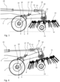
- Figs. 1 and 2 show a side view of a preferred embodiment of the agricultural implement according to the invention in the working position.
- the agricultural implement may be a tedder 1 having a main frame 3 which can comprise on one end a tow hook or tow ring 2 configured to engage with the tow hitch of a towing vehicle (not shown) and on the other end a common axle 5 configured for attaching a wheel chassis and a plurality of tedder units as will be explained below.
- a mounting portion 4 may be provided at which at least one central actuator may be attached which will also be explained in detail below.
- a wheel support 6 having a main wheel 7 rotatably attached on either side of the agricultural implement 1, and the tedder frame 8 to which the plurality of tedder units 10 may be attached.
- Each tedder unit 10 may essentially comprise a rotary rake 11 having a plurality of forks or tines 12 which are configured to move, swath or otherwise distribute freshly cut hay or other crop on a field.
- the plurality of tedder units 10 may in the present embodiment be distributed on the tedder frame 8 transversely to the driving direction of the agricultural implement one such that on either side of the main frame 3 an equal number of tedder units 10 covers an area as wide as possible.
- the tedder frame 8 may comprise side portions, hinges and drives which are configured to enable a folding of tedder units 10 onto the tedder frame 8 and to supply energy to drive the rotary rakes 11.
- a plurality of tedder wheels 13 may be positioned along the width of the tedder frame 8, preferably one tedder wheel 13 per tedder unit 10.
- the drive for rotatably driving the rotary rakes 11 may, for example, be designed with drive shafts which are propelled by the PTO of the towing unit.
- the side parts of the tedder frame 8 are fully extended and articulated in such a way that ground surface inequalities such as bumps and the like may be compensated.
- the tedder units In addition to the pivoting motion of the side portions of the tedder frame 8, the tedder units have a further degree of freedom by rotating the tedder frame 8 in relatively small ranges around the common axle 5.
- the wheel support 6 and the tedder frame 8 are advantageously connected in a common axle 5 as mentioned above. Furthermore, those two components are connected by at least one adjustment actuator which is located between a first attachment point on the wheel support 6 and a second attachment point on the tedder frame 8.
- the first attachment point may be a first pivot axis 14 which is attached to the wheel support 6 at a central portion thereof
- the second attachment point may be a second pivot axis 15 located on an attachment portion of the tedder frame 8 which is positioned towards the common axle 5.
- Arranged between the first pivot axis 14 and the second pivot axis 15 may be a rod having a first adjustment actuator 16 and a second adjustment actuator 17.
- the first adjustment actuator 16 may be a hydraulic cylinder 16 and the second adjustment actuator 17 may be a manual spindle apparatus 17.
- the hydraulic cylinder 16 may be powered by a hydraulic line connected with the towing vehicle.
- the first and second adjustment actuators 16, 17 together with the rod form a part of a lifting unit which is configured to set and/or adjust the relative position of the wheel support 6 with respect to the tedder frame 8.
- the setting of the adjustment actuators determines the length or distance between the first pivot axis 14 and the second pivot axis 15 such that the wheel frame 6 and the tedder frame 8 form a rigid unit acting like a boogie chassis which may pivot around the common axle 5. It is understood that when the distance between the first pivot axis 14 and the second pivot axis 15 is shortened and the relative position between the main frame 3 and the wheel support 6 is not changed then the tedder frame 8 pivots slightly around the common axle 5 such that its free portion is lifted relative to the ground surface.
- a guiding portion 18 may be included in the tedder frame 8 at the free and opposite of the tedder units 10, the guiding portion 18 being configured to guide and limit the movement of the tedder frame 8 by being connected to at least one central actuator. It is noted that the guiding portion 18 may be integral with the tedder frame 8 or may be a separate component attached to the tedder frame.
- the at least one central actuator may comprise a first central actuator 20 and a second central actuator 21 both acting on a rod extending between the mounting portion 4 of the main frame 3 and the guiding portion 18 of tedder frame 8.
- the at least one central actuator may include a single central actuator, preferably a hydraulic cylinder which, in combination with a position detection unit, can be actuated as needed.
- a long hole 19 may be arranged as part of the guiding portion 18 wherein a guiding pin 22 formed on one and of the rod is accommodated within the long hole 19. Therefore, the movement of the tedder frame 8 is restricted by the movement of the guiding pin 22 within the long hole 19. This limitation of movement has several effects which will be explained below.
- a first, predetermined movement of the guiding pin 22 within the long hole 19 is achieved by changing the extension of any of the adjustment actuators 16, 17 or central actuators 20, 21.
- the predetermined movement of the second adjustment actuator 17 which may be a manual spindle handled by the operator of the implement effects an adjustment of the height of the tines 12 of every tedder unit 10. Looking at Fig. 2 , for example, extending the length between the first pivot axis 14 and the second pivot axis 15 will lift the tines 12 of every tedder unit 10 on the forward side of the tedder wheel 13, i.e. where the times 12 are intended to engage with the crop lying on the ground surface.
- a second, independent movement of the entire wheel support/tedder frame combination may occur when the agricultural implement 1 is pulled over an even ground surface.
- the main wheel 7 may impinge on a stone or rock on the ground surface such that it is slightly lifted.
- the lifting of the main wheel 7 will effect a pivoting movement of the rigid structure about the common axle 5.
- This is enabled by the limited, but possible movement of the guiding pin 22 within the long hole 19. Within the range of travel of the guiding pin 22 in the long hole 19 there is thus a possibility of a tilting movement of the boogie-like structure such that uneven ground surface passages may be compensated without exerting any forces on the main frame 3.
- Fig. 3 shows a side view of the embodiment of Figs. 1 and 2 in an intermediary position where the times 12 of the tedder units 10 have been lifted above the ground surface.
- This predetermined or intermediary position was achieved by extending the distance between the first pivot axis 14 and the second pivot axis 15 by means of the first adjustment actuator 16 and/or the second adjustment actuator 17. It can clearly be seen in Fig. 3 that the guiding pin 22 within the long hole 19 has reached a first stop position which is the leftmost position in the shown embodiment. Further, the angle between the wheel support 6 and the tedder frame 8 has changed accordingly bringing the main wheel 7 and the tedder wheels 13 slightly closer together.
- the headland position of the agricultural implement 1 is shown in a side view of Fig. 4 .
- the central actuators 20, 21 or only the central actuator 20 were actuated so as to decrease the length of the rod on which they are located.
- This causes the tedder frame 8 including the tedder units 10 and the wheel support 6 to be pulled towards the towing unit.
- the wheel support and the tedder frame 8 are pivotably attached to the main frame 3 at the common axle 5 the pulling movement of the central actuators 20, 21 effects a pivoting movement of the entire boogie-like structure lifting the tedder wheels 13 from the ground surface.
- Fig. 4 shows that the angle between the wheel support 6 and the tedder frame 8 remains constant with respect to the intermediary position shown in Fig.
- the respective position of the central actuators has changed. In this position, the agricultural implement one can be safely moved in a headland turn such that none of the tedder units 10 may engage with the ground surface. As seen in figures 3 and 4 , the height of the tedder units 10 above the ground surface is determined by the adjustment actuators 16, 17 as well as the central actuators 20, 21.
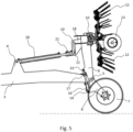
- Fig. 5 the agricultural implement 1 is shown in the transport position. This position starts from the headland position, shown in Fig. 4 , in which hydraulic cylinders or other actuators firstly fold the side portions (not shown) of the tedder frame 8 onto one another so that the overall with of the agricultural implement 1 will not exceed its allowed value in the transport position. Then, the central actuator(s) 20, 21 may be actuated, for example by moving the hydraulic cylinder(s) of the actuator(s) to its/their shortest length.
Landscapes
- Life Sciences & Earth Sciences (AREA)
- Environmental Sciences (AREA)
- Engineering & Computer Science (AREA)
- Mechanical Engineering (AREA)
- Soil Sciences (AREA)
- Zoology (AREA)
- Agricultural Machines (AREA)
Priority Applications (2)
| Application Number | Priority Date | Filing Date | Title |
|---|---|---|---|
| EP21204838.3A EP4173469A1 (fr) | 2021-10-26 | 2021-10-26 | Tedder rotatif avec dispositif de levage |
| US17/973,917 US20230127688A1 (en) | 2021-10-26 | 2022-10-26 | Rotary Tedder |
Applications Claiming Priority (1)
| Application Number | Priority Date | Filing Date | Title |
|---|---|---|---|
| EP21204838.3A EP4173469A1 (fr) | 2021-10-26 | 2021-10-26 | Tedder rotatif avec dispositif de levage |
Publications (1)
| Publication Number | Publication Date |
|---|---|
| EP4173469A1 true EP4173469A1 (fr) | 2023-05-03 |
Family
ID=78413709
Family Applications (1)
| Application Number | Title | Priority Date | Filing Date |
|---|---|---|---|
| EP21204838.3A Pending EP4173469A1 (fr) | 2021-10-26 | 2021-10-26 | Tedder rotatif avec dispositif de levage |
Country Status (2)
| Country | Link |
|---|---|
| US (1) | US20230127688A1 (fr) |
| EP (1) | EP4173469A1 (fr) |
Citations (6)
| Publication number | Priority date | Publication date | Assignee | Title |
|---|---|---|---|---|
| JPS57167612U (fr) * | 1981-04-16 | 1982-10-22 | ||
| JPS63160503A (ja) * | 1986-12-25 | 1988-07-04 | 株式会社クボタ | 昇降制御装置 |
| EP2436260A1 (fr) * | 2010-10-01 | 2012-04-04 | CLAAS Saulgau GmbH | Faneuse destinée à retourner des récoltes se trouvant sur le sol |
| EP2499897A1 (fr) | 2011-03-18 | 2012-09-19 | Alois Pöttinger Maschinenfabrik Ges. m.b.H. | Faneuse |
| US20140102069A1 (en) * | 2007-11-05 | 2014-04-17 | Lely Patent N.V. | Drawn agricultural machine |
| EP3245857A1 (fr) * | 2016-05-19 | 2017-11-22 | Kuhn S.A. | Machine agricole comportant un système de report de charge sécurisé |
-
2021
- 2021-10-26 EP EP21204838.3A patent/EP4173469A1/fr active Pending
-
2022
- 2022-10-26 US US17/973,917 patent/US20230127688A1/en active Pending
Patent Citations (6)
| Publication number | Priority date | Publication date | Assignee | Title |
|---|---|---|---|---|
| JPS57167612U (fr) * | 1981-04-16 | 1982-10-22 | ||
| JPS63160503A (ja) * | 1986-12-25 | 1988-07-04 | 株式会社クボタ | 昇降制御装置 |
| US20140102069A1 (en) * | 2007-11-05 | 2014-04-17 | Lely Patent N.V. | Drawn agricultural machine |
| EP2436260A1 (fr) * | 2010-10-01 | 2012-04-04 | CLAAS Saulgau GmbH | Faneuse destinée à retourner des récoltes se trouvant sur le sol |
| EP2499897A1 (fr) | 2011-03-18 | 2012-09-19 | Alois Pöttinger Maschinenfabrik Ges. m.b.H. | Faneuse |
| EP3245857A1 (fr) * | 2016-05-19 | 2017-11-22 | Kuhn S.A. | Machine agricole comportant un système de report de charge sécurisé |
Also Published As
| Publication number | Publication date |
|---|---|
| US20230127688A1 (en) | 2023-04-27 |
Similar Documents
| Publication | Publication Date | Title |
|---|---|---|
| EP1364569B1 (fr) | Tondeuse | |
| EP3725150B1 (fr) | Outil agricole | |
| US4573309A (en) | Pull-type windrower | |
| JPS6366487B2 (fr) | ||
| EP3259978B1 (fr) | Système de commande d'outil agricole | |
| AU2016335152B2 (en) | Carrier assembly | |
| US20140373496A1 (en) | Harvesting machine comprising a servo-control means for the lifting height of a work tool | |
| EP3082399B1 (fr) | Râteau agricole | |
| US4662161A (en) | Pull-type windrower | |
| US4776157A (en) | Machine for working grass, hay or other crops on the field | |
| CA2890534C (fr) | Dispositif de recolte de produits agricoles longs et accessoire agricole autopropulse destine a la recolte de produits agricoles comportant ledit dispositif | |
| EP4173469A1 (fr) | Tedder rotatif avec dispositif de levage | |
| HU203440B (en) | Collapsible trailed underframe for plough-land implements particularly rotary scythes | |
| DK1488685T4 (da) | Høbjergningsmaskine | |
| EP0701771B1 (fr) | Machine agricole | |
| EP0900515A2 (fr) | Structure porteuse d'outils | |
| EP0622006B1 (fr) | Maschine de fenaison | |
| DK2661952T3 (en) | Hay harvesting machine | |
| DE102010047071B4 (de) | Heuwerbungsmaschine | |
| EP1668977B1 (fr) | Machine de fenaison | |
| EP3092888B1 (fr) | Machine agricole | |
| EP1262098B1 (fr) | Dispositif d'andainage | |
| EP4101277A1 (fr) | Appareil agricole remorqué | |
| EP0887010B1 (fr) | Dispositif de réglage d'une machine agricole telle qu'une machine de fenaison | |
| EP2108244A1 (fr) | Faneuse |
Legal Events
| Date | Code | Title | Description |
|---|---|---|---|
| PUAI | Public reference made under article 153(3) epc to a published international application that has entered the european phase |
Free format text: ORIGINAL CODE: 0009012 |
|
| STAA | Information on the status of an ep patent application or granted ep patent |
Free format text: STATUS: THE APPLICATION HAS BEEN PUBLISHED |
|
| AK | Designated contracting states |
Kind code of ref document: A1 Designated state(s): AL AT BE BG CH CY CZ DE DK EE ES FI FR GB GR HR HU IE IS IT LI LT LU LV MC MK MT NL NO PL PT RO RS SE SI SK SM TR |
|
| STAA | Information on the status of an ep patent application or granted ep patent |
Free format text: STATUS: REQUEST FOR EXAMINATION WAS MADE |
|
| 17P | Request for examination filed |
Effective date: 20231103 |
|
| RBV | Designated contracting states (corrected) |
Designated state(s): AL AT BE BG CH CY CZ DE DK EE ES FI FR GB GR HR HU IE IS IT LI LT LU LV MC MK MT NL NO PL PT RO RS SE SI SK SM TR |