EP4172574B1 - Fluiddosiervorrichtung mit verminderter kreuzkontamination - Google Patents
Fluiddosiervorrichtung mit verminderter kreuzkontamination Download PDFInfo
- Publication number
- EP4172574B1 EP4172574B1 EP21829802.4A EP21829802A EP4172574B1 EP 4172574 B1 EP4172574 B1 EP 4172574B1 EP 21829802 A EP21829802 A EP 21829802A EP 4172574 B1 EP4172574 B1 EP 4172574B1
- Authority
- EP
- European Patent Office
- Prior art keywords
- fluid
- valve
- tube
- metering device
- recited
- Prior art date
- Legal status (The legal status is an assumption and is not a legal conclusion. Google has not performed a legal analysis and makes no representation as to the accuracy of the status listed.)
- Active
Links
Images


Classifications
-
- G—PHYSICS
- G01—MEASURING; TESTING
- G01F—MEASURING VOLUME, VOLUME FLOW, MASS FLOW OR LIQUID LEVEL; METERING BY VOLUME
- G01F15/00—Details of, or accessories for, apparatus of groups G01F1/00 - G01F13/00 insofar as such details or appliances are not adapted to particular types of such apparatus
- G01F15/005—Valves
-
- G—PHYSICS
- G01—MEASURING; TESTING
- G01F—MEASURING VOLUME, VOLUME FLOW, MASS FLOW OR LIQUID LEVEL; METERING BY VOLUME
- G01F11/00—Apparatus requiring external operation adapted at each repeated and identical operation to measure and separate a predetermined volume of fluid or fluent solid material from a supply or container, without regard to weight, and to deliver it
- G01F11/10—Apparatus requiring external operation adapted at each repeated and identical operation to measure and separate a predetermined volume of fluid or fluent solid material from a supply or container, without regard to weight, and to deliver it with measuring chambers moved during operation
- G01F11/12—Apparatus requiring external operation adapted at each repeated and identical operation to measure and separate a predetermined volume of fluid or fluent solid material from a supply or container, without regard to weight, and to deliver it with measuring chambers moved during operation of the valve type, i.e. the separating being effected by fluid-tight or powder-tight movements
-
- G—PHYSICS
- G01—MEASURING; TESTING
- G01F—MEASURING VOLUME, VOLUME FLOW, MASS FLOW OR LIQUID LEVEL; METERING BY VOLUME
- G01F15/00—Details of, or accessories for, apparatus of groups G01F1/00 - G01F13/00 insofar as such details or appliances are not adapted to particular types of such apparatus
- G01F15/12—Cleaning arrangements; Filters
-
- G—PHYSICS
- G01—MEASURING; TESTING
- G01F—MEASURING VOLUME, VOLUME FLOW, MASS FLOW OR LIQUID LEVEL; METERING BY VOLUME
- G01F15/00—Details of, or accessories for, apparatus of groups G01F1/00 - G01F13/00 insofar as such details or appliances are not adapted to particular types of such apparatus
- G01F15/18—Supports or connecting means for meters
-
- G—PHYSICS
- G01—MEASURING; TESTING
- G01F—MEASURING VOLUME, VOLUME FLOW, MASS FLOW OR LIQUID LEVEL; METERING BY VOLUME
- G01F3/00—Measuring the volume flow of fluids or fluent solid material wherein the fluid passes through the meter in successive and more or less isolated quantities, the meter being driven by the flow
- G01F3/02—Measuring the volume flow of fluids or fluent solid material wherein the fluid passes through the meter in successive and more or less isolated quantities, the meter being driven by the flow with measuring chambers which expand or contract during measurement
- G01F3/04—Measuring the volume flow of fluids or fluent solid material wherein the fluid passes through the meter in successive and more or less isolated quantities, the meter being driven by the flow with measuring chambers which expand or contract during measurement having rigid movable walls
- G01F3/06—Measuring the volume flow of fluids or fluent solid material wherein the fluid passes through the meter in successive and more or less isolated quantities, the meter being driven by the flow with measuring chambers which expand or contract during measurement having rigid movable walls comprising members rotating in a fluid-tight or substantially fluid-tight manner in a housing
Definitions
- the present disclosure relates to a fluid metering device. More particularly, the present disclosure relates to a fluid metering device for measuring at least two fluids with reduced cross-contamination.
- a fluid metering device In an immunoassay test, a fluid metering device is required to separate and measure at least two fluids (e.g., a wash solution and water).
- a conventional immunoassay analyzer e.g., Atellica ® IM analyzer
- Atellica ® IM analyzer can fulfill the fluid separation and measurement functions using a plurality of displacement pumps, an independent pump manifold for each displacement pump, and an additional 3-layer 28-valve manifold to dispense the fluids (e.g., a wash solution and water).
- this 3-layer manifold is traditionally very expensive.
- US 6 382 035 B1 discloses multifunction valve apparatus for use with a Probe-In-Loop (PIL) architecture sample injection assembly which enables both Partial-Fill and Complete-Fill injections.
- the rotor element is rotatable about a rotation axis relative the stator between: a Load Position, an Overfill Position, and an Injection Position.
- a first bridge channel fluidly couples a metering syringe to the sample loop assembly enabling the probe to aspirate one of a discrete volume of sample into the probe, during a Partial-Fill Mode, and a second volume of sample into the probe, during a Complete-Fill Mode.
- a second bridge channel fluidly couples a downstream loop portion to a waste port, and the first bridge channel fluidly couples the metering syringe to an upstream loop portion of the sample loop assembly.
- the invention comprises a fluid metering device according to claim 1.
- Embodiments of the present invention address and overcome one or more of the above shortcomings and drawbacks, by providing a fluid metering device for measuring at least two fluids with reduced cross-contamination.
- Embodiments provide a fluid metering device, comprising: a metering pump for measuring a volume of each fluid; a manifold connected to the metering pump, wherein the manifold includes a plurality of fluid channels, and the manifold is used for communicating between the valve assembly and each port.
- Embodiments further provide a fluid metering device, wherein the first fluid is supplied at an elevated pressure, wherein the first valve is a two-way valve, and the second valve, the third valve, and the fourth valve are all three-way valves.
- Embodiments further provide a fluid metering device, further comprising a booster pump connected to the first fluid supply port.
- Embodiments further provide a fluid metering device, further comprising a tube winding case accommodating the first valve and the second valve, wherein the first tube and the second tube wrap around the tube winding case separately.
- Embodiments further provide a fluid metering device, further comprising a first circular cover for covering the first tube; and a second circular cover for covering the second tube.
- Embodiments further provide a fluid metering device, further comprising a third tube connected to the second fluid supply port, a fourth tube connected to the waste discharge port, and a fifth tube connected to the first fluid supply port.
- Embodiments further provide a fluid metering device, further comprising a connecting plate on top of the manifold, wherein the first tube, the second tube, the third tube, the fourth tube, and the fifth tube are connected to the manifold through the connecting plate.
- Embodiments further provide a fluid metering device, wherein the connecting plate includes a plurality of slots communicating with the plurality of fluid channels in the manifold, and the first tube, the second tube, the third tube, the fourth tube, and the fifth tube are connected to the plurality of slots.
- Embodiments further provide a fluid metering device, the plurality of slots includes a first slot connected to the third tube, a second slot connected to one end of the second tube, a third slot connected to the fifth tube, a fourth slot connected to one end of the first tube; a fifth slot connected to the other end of the second tube, a sixth slot connected to the fourth tube, and a seventh slot connected to the other end of the first tube.
- Embodiments further provide a fluid metering device, wherein a capacity of the second tube is greater than or equal to a required amount of the second fluid.
- Embodiments further provide a fluid metering device, wherein the first valve, the second valve, the third valve, and the fourth valve are all three-way valves, and the first fluid and the second fluid are supplied at an atmospheric pressure.
- Embodiments further provide a fluid metering device, further comprising a booster pump connected to the second fluid supply port, so that the second fluid is supplied at an elevated pressure, wherein the valve assembly further comprises a fifth valve connected to the fourth valve, the third valve, and the waste discharge port, wherein the fifth valve is a three-way valve.
- Embodiments further provide a fluid metering device, further comprising a booster pump connected to the second fluid supply port, so that the second fluid is supplied at an elevated pressure, wherein the valve assembly further comprises a sixth valve connected to the waste discharge port and the second tube, wherein the sixth valve is a two-way valve.
- Embodiments further provide a fluid metering device, wherein the metering pump is a positive displacement pump.
- Embodiments further provide a fluid metering device, wherein the first fluid is water, and the second fluid is a wash solution selected from a group comprising Potassium Chloride, Potassium Phosphate, Disodium Phosphate, Sodium Chloride, Sodium Azide, Disodium Ethylenediaminetetraacetic Acid, and Polysorbate 20.
- the first fluid is water
- the second fluid is a wash solution selected from a group comprising Potassium Chloride, Potassium Phosphate, Disodium Phosphate, Sodium Chloride, Sodium Azide, Disodium Ethylenediaminetetraacetic Acid, and Polysorbate 20.
- the invention according to claim 1 provides a fluid metering device, comprising a first fluid supply port for receiving a first fluid, a first fluid dispense port for dispensing the first fluid, a second fluid supply port for receiving a second fluid, a second fluid dispense port for dispensing the second fluid, a waste discharge port for discharging a mixture of the first fluid and the second fluid, a metering pump for measuring a volume of each of the first fluid and the second fluid, a valve assembly used for directing the first fluid from the first fluid supply port to the first fluid dispense port, directing the second fluid from the second fluid supply port to the second fluid dispense port, and directing the mixture to the waste discharge port, wherein the valve assembly includes a first valve connected to the first fluid supply port and the metering pump, a second valve connected to the first fluid dispense port, a third valve connected to the second valve and the waste discharge port, and a fourth valve connected to the third valve, the second fluid supply port and the second fluid dispense port,
- the following disclosure describes embodiments directed to a fluid metering device that utilizes a single-precision metering pump, a single manifold, and a valve assembly to precisely measure two different fluids while minimizing cross-contamination between the fluids. Because only a single-precision metering pump and a single manifold are required in the fluid metering device described herein, the cost is significantly reduced compared to conventional multi-pump systems.
- the fluid metering device can be used for any scenario where fluid separation is required including, without limitation, immunoassay wash separation.
- a single machined manifold having fluidic channels is connected to a precision metering pump and a valve assembly including four valves to precisely dispense water and a wash solution, while minimizing cross-contamination between the water and the wash solution.
- Two tubes are connected externally to the manifold in a "loop" configuration for minimal cross-contamination.
- an expensive layered manifold e.g., 3-layer manifold
- FIG. 1 illustrates a block diagram depicting a working principle of a fluid metering device 100, in accordance with different embodiments described herein.
- the fluid metering device 100 includes four valves (the first valve 104, the second valve 106, the third valve 108, and the fourth valve 110) and a metering pump 102.
- the first valve 104 is a two-way valve
- the second valve 106, the third valve 108, and the fourth valve 110 are three-way valves.
- all the four valves can be three-way valves.
- the metering pump 102 can aspirate water from the water supply port 126, and dispense the water to the waste discharge port 124, so that waste in the first tube 120 can be discharged.
- the metering pump 102 can aspirate water from the water supply port 126, and dispense the water to the water dispense port 131.
- the water dispense port 131 can then dispense water externally to another device (not shown in FIG. 1 ).
- the metering pump 102 can aspirate a wash solution from the wash supply port 128 into the second tube 122.
- the length of the second tube 122 may be selected depending on the required amount of wash solution, and the second tube 122 itself can accommodate all the required amount of wash solution.
- the capacity of the second tube 122 can be greater than or equal to the required amount of wash solution.
- the aspirated wash solution is a little (e.g., several milliliters) more than the required amount of wash solution to be dispensed, because some wash solution may be mixed with the water and thus contaminated, and has to be discharged from the waste discharge port 124.
- the second tube 122 is full of the wash solution, and the extra wash solution enters into the first tube 120 and is mixed with the water in the first tube 120.
- the wash solution in the second tube 122 can be dispensed externally to another device through the wash dispense port 130. Because the second tube 122 can accommodate enough wash solution for dispensation, thus no liquid from the first tube 120 will be dispensed out.
- the third valve 108 can be switched to connect to the waste discharge port 124. While the first valve 104 is opened and the second valve 106 is connected to the third valve 108, the metering pump 102 can aspirate water from the water supply port 126, and dispense the water to the waste discharge port 124. Thus, the waste (a mixture of wash solution and water) in the first tube 120 can be discharged from the waste discharge port 124.
- the fluid metering device 100 further includes a booster pump 132 connected to the water supply port 126.
- the booster pump 132 can increase the pressure of the water to, e.g., 11 psi (pound-force per square inch).
- the pressurized water allows for more water volume to be flushed through the fluid metering device 100 compared to the water at atmospheric pressure.
- the water pressure can be increased by another approach, e.g., a water tank with compressed air, or an increase in water elevation.
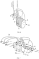
- FIG. 2 illustrates a structure of the fluid metering device 100, in accordance with different embodiments described herein.
- the fluid metering device 100 is a compact assembly, instead of multiple disconnected assemblies.
- the fluid metering device 100 comprises a metering pump 102, a valve assembly 101 including four valves (i.e., the first valve 104, the second valve 106, the third valve 108, the fourth valve 110 as shown in FIG. 1 ), and a manifold 202 containing fluid channels.
- the fluid metering device 100 further includes a plurality of tubes (i.e., the first tube 120 for connecting the second valve 106 and the third valve 108, and the second tube 122 for connecting the third valve 108 and the fourth valve 110, the third tube 114 for wash solution supply, the fourth tube 116 for waste discharge, the fifth tube 118 for water supply), a connecting plate 204 for easy connection, and a tube winding case 206 around which the first tube 120 and the second tube 122 wrap.
- a plurality of tubes i.e., the first tube 120 for connecting the second valve 106 and the third valve 108, and the second tube 122 for connecting the third valve 108 and the fourth valve 110, the third tube 114 for wash solution supply, the fourth tube 116 for waste discharge, the fifth tube 118 for water supply
- a connecting plate 204 for easy connection
- a tube winding case 206 around which the first tube 120 and the second tube 122 wrap.
- two fluid tubes are used as buffers between different fluids (e.g., a wash solution and water).
- the two fluid tubes may be made of low-cost tubes, instead of expensive fluid channels within a layered manifold as in conventional systems.
- the valve assembly 101 enables a waste (i.e., a mixture of a wash solution and water) to be discharged through a waste discharge port 124 (shown in FIG. 1 ), or the two fluid tubes to be linked together.
- the valve assembly 101 can direct each of the two fluids either through one of the fluid tubes or to one of the dispense ports.
- the metering pump 102 is a precision metering pump, which is a positive displacement pump.
- the manifold 202 is used to provide most of the connections shown in FIG. 1 .
- the manifold 202 can be used to connect between the water supply port 126 and the first valve 104, between the first valve 104 and the metering pump 102, between the metering pump 102 and the second valve 106, between the second valve 106 and the first tube 120, between the first tube 120 and the third valve 108, between the third valve 108 and the waste discharge port 124, between the third valve 108 and the second tube 122, between the second tube 122 and the fourth valve 110, between the fourth valve 110 and the wash dispense port 130, and between the fourth valve 110 and the wash supply port 128.
- the manifold 202 only has straight channels for the fluids (e.g., water, wash solution, or waste), and allows for straightforward machining operations to fabricate, instead of complex layered construction, which can significantly reduce the cost.
- the connecting plate (also called a "gang" plate) 204 is provided on top of the manifold 202 and connected to the manifold 202 and the tube winding case 206.
- FIG.3 illustrates a layout of the connecting plate 204, in accordance with different embodiments described herein. Referring to FIGS. 1 and 3 , the connecting plate 204 includes seven slots which communicate with fluid channels of the manifold 202 respectively.
- the first slot 302 is used to connect to the third tube 114 for wash solution supply; the second slot 304 is used to connect to one end of the second tube 122 for connecting the third valve 108 and the fourth valve 110; the third slot 306 is used to connect to the fifth tube 118 for water supply; the fourth slot 308 is used to connect to one end of the first tube 120 for connecting the second valve 106 and the third valve 108; the fifth slot 310 is used to connect to the other end of the second tube 122; the sixth slot 312 is used to connect to the fourth tube 116 for waste discharge; the seventh slot 314 is used to connect to the other end of the first tube 120.
- the slot positions correspond to positions and functions of the fluid channels in the manifold 202.
- FIG. 4 illustrates an explosive view of the tube winding case 206, in accordance with different embodiments described herein.
- the tube winding case 206 includes a case body 402, the first tube 120, a first circular cover 404 for covering the first tube 120, the second tube 122, and a second circular cover 406 for covering the second tube 122.
- the case body 402 accommodates two valves, e.g., the first valve 104 and the second valve 106.
- the second tube 122 for accommodating a wash solution is much longer than the first tube 120 for accommodating water or waste (e.g., four or five times longer); thus, the second tube 122 may have more loops than that of the first tube 120.
- the first tube 120 and the second tube 122 may wrap around the tube winding case 206 separately.
- the first circular cover 404 and the second circular cover 406 can accommodate and cover the first tube 120 and the second tube 122, respectively.
- FIGS. 5 and 6 illustrate a structure of the tube winding case 206 connected to the connecting plate 204, in accordance with different embodiments described herein.
- FIG. 5 depicts the tube winding case 206 including the first circular cover 404 and the second circular cover 406, while FIG. 6 depicts the tube winding case 206 removing the first circular cover 404 and the second circular cover 406.
- FIG. 7 illustrates another structure of the fluid metering device 700, in accordance with different embodiments described herein.
- the difference between this embodiment and the embodiment as shown in FIG. 2 is how the tube winding case is employed.
- the first tube 120 and the second tube 122 directly wrap around two valves (e.g., the first valve 104 and the second valve 106).
- the tube winding case 702 encloses the first tube 120 and the second tube 122.
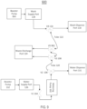
- FIG. 8 shows another block diagram depicting a working principle of a fluid metering device 800, in accordance with different embodiments described herein.
- a pressurized source i.e., booster pump 132
- the wash solution e.g., Potassium Chloride, Potassium Phosphate, Disodium Phosphate, Sodium Chloride, Sodium Azide, Disodium Ethylenediaminetetraacetic Acid, Polysorbate 20, etc.
- the wash solution e.g., Potassium Chloride, Potassium Phosphate, Disodium Phosphate, Sodium Chloride, Sodium Azide, Disodium Ethylenediaminetetraacetic Acid, Polysorbate 20, etc.
- the first valve 802 is a three-way valve, and the water from the water supply port 126 is provided at atmospheric pressure. No booster pump is provided in this embodiment, and the metering pump 102 can dispense the water to the second valve 106 through the first valve 802.
- FIG. 9 illustrates another block diagram depicting a working principle of a fluid metering device 900, in accordance with different embodiments described herein.
- a second booster pump 904 is provided and connected to the wash supply port 128, and the wash solution from the wash supply port 128 can also be provided at an elevated pressure, e.g., 12 psi.
- a fifth valve 902 (a three-way valve) is provided between the third valve 108 and the second tube 122.
- the fifth valve 902 and the fourth valve 110 are opened to allow the wash solution at an elevated pressure (a pressure higher than the atmospheric pressure) to flow from the wash supply port 128 to the waste discharge port 124.
- the fourth valve 110 is closed to stop the wash supply, and the fifth valve 902 is still opened to allow the pressure to dissipate to the waste discharge port 124.
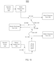
- FIG. 10 shows another block diagram depicting a working principle of a fluid metering device 950, in accordance with different embodiments described herein.
- a second booster pump 904 is provided and connected to the wash supply port 128, and the wash solution from the wash supply port 128 can also be provided at an elevated pressure, e.g., 13 psi.
- a sixth valve 906 (a two-way valve) is provided between the tube 122 and the waste discharge port 124. In a scenario, the sixth valve 906 is opened to allow the wash solution at an elevated pressure to flow from the wash supply port 128 to the waste discharge port 124.
- the fourth valve 110 is closed to stop the wash supply, and the sixth valve 906 is still opened to allow the pressure to dissipate to the waste discharge port 124, while the third valve 108 and the metering pump 102 are used to dissipate the pressure to the first tube 120.
- the fluid metering device 100 is a compact assembly, instead of multiple disconnected assemblies. Thus, all the components are positioned near to each other, and distances between components are reduced. Accordingly, fluid volumes between components are reduced. In turn, the reduction in fluids allows the fluid metering device 100 to be designed as a stiff fluidic system with a high resonant frequency, well above frequencies of the components, because the resonant frequency of a fluid channel is inversely proportional to the length of the fluid channel. Accordingly, oscillations of the fluid metering device 100 can be significantly reduced, thus decreasing settling time after pump motion stops.
- FIGS. 11A - 11D show improved metering accuracy and precision in an immunoassay analyzer system utilizing fluid metering device 100.
- FIG. 11A and FIG. 11B depict metering inaccuracy and imprecision for water at a dispense speed of 800 uL/s, compared to the specification requirements.
- FIG. 11C and FIG. 11D depict metering inaccuracy and imprecision for a wash solution at a dispense speed of 800 uL/s, compared to the specification requirements.
Landscapes
- Physics & Mathematics (AREA)
- Fluid Mechanics (AREA)
- General Physics & Mathematics (AREA)
- Feeding, Discharge, Calcimining, Fusing, And Gas-Generation Devices (AREA)
- Measuring Volume Flow (AREA)
- Sampling And Sample Adjustment (AREA)
- Automatic Analysis And Handling Materials Therefor (AREA)
- Loading And Unloading Of Fuel Tanks Or Ships (AREA)
Claims (17)
- Fluiddosiervorrichtung umfassend:einen ersten Fluidzufuhranschluss (126) zum Aufnehmen eines ersten Fluids;einen ersten Fluidausgabeanschluss (131) zum Ausgeben des ersten Fluids;einen zweiten Fluidzufuhranschluss (128) zum Aufnehmen eines zweiten Fluids;einen zweiten Fluidausgabeanschluss (130) zum Ausgeben des zweiten Fluids;einen Abfallauslassanschluss (124) zum Auslassen eines Gemischs des ersten Fluids und des zweiten Fluids;eine Dosierpumpe (102) zum Messen eines Volumens von jedem von dem ersten Fluid und dem zweiten Fluid; undeine Ventilbaugruppe (101), verwendet zum Lenken des ersten Fluids von dem ersten Fluidzufuhranschluss zu dem ersten Fluidausgabeanschluss (131), Lenken des zweiten Fluids von dem zweiten Fluidzufuhranschluss (128) zu dem zweiten Fluidausgabeanschluss (130) und Lenken des Gemischs zu dem Abfallauslassanschluss (124),dadurch gekennzeichnet, dass die Ventilbaugruppe (101) ein erstes Ventil (104), das mit dem ersten Fluidzufuhranschluss (126) und der Dosierpumpe (102) verbunden ist, ein zweites Ventil (106), das mit dem ersten Fluidzufuhranschluss (131) verbunden ist, ein drittes Ventil (108), das mit dem zweiten Ventil (106) und dem Abfallauslassanschluss (124) verbunden ist, und ein viertes Ventil (110), das mit dem dritten Ventil (108), dem zweiten Fluidzufuhranschluss (128) und dem zweiten Fluidausgabeanschluss (130) verbunden ist, enthält; unddadurch, dass die Fluiddosiervorrichtung ferner ein erstes Rohr (120), das zwischen dem zweiten Ventil (106) und dem dritten Ventil (108) angeschlossen ist, zum Aufnehmen des Gemisches oder des ersten Fluids aufweist, wobei das erste Rohr (120) dafür gestaltet ist, zu verhindern, dass das zweite Fluid das zweite Ventil (106) erreicht; undein zweites Rohr (122), das zwischen dem dritten Ventil (108) und dem vierten Ventil (110) angeschlossen ist, zum Aufnehmen des zweiten Fluids, wobei das zweite Rohr (122) dafür gestaltet ist, eine erforderliche Menge des zweiten Fluids aufzunehmen.
- Fluiddosiervorrichtung nach Anspruch 1, wobei das erste Fluid unter einem erhöhten Druck zugeführt wird, wobei das erste Ventil (104) ein Zweiwegventil ist und das zweite Ventil (106), das dritte Ventil (108) und das vierte Ventil (110) alle Dreiwegventile sind.
- Fluiddosiervorrichtung nach Anspruch 1, wobei das erste Ventil (104), das zweite Ventil (106), das dritte Ventil (108) und das vierte Ventil (110) alle Dreiwegventile sind und das erste Fluid und das zweite Fluid unter einem atmosphärischen Druck zugeführt werden.
- Fluiddosiervorrichtung nach Anspruch 1, ferner umfassend eine Boosterpumpe (132), die mit dem zweiten Fluidzufuhranschluss (128) verbunden ist, so dass das zweite Fluid unter einem erhöhten Druck zugeführt wird, wobei die Ventilbaugruppe (101) ferner ein fünftes Ventil (902) umfasst, das mit dem vierten Ventil (110), dem dritten Ventil (108) und dem Abfallauslassanschluss (124) verbunden ist, wobei das fünfte Ventil (902) ein Dreiwegventil ist.
- Fluiddosiervorrichtung nach Anspruch 1, ferner umfassend eine Boosterpumpe (132), die mit dem zweiten Fluidzufuhranschluss (128) verbunden ist, so dass das zweite Fluid unter einem erhöhten Druck zugeführt wird, wobei die Ventilbaugruppe (101) ferner ein sechstes Ventil (906) umfasst, das mit dem Abfallauslassanschluss (124) und dem zweiten Rohr (122) verbunden ist, wobei das sechste Ventil (906) ein Zweiwegventil ist.
- Fluiddosiervorrichtung nach Anspruch 1, ferner umfassend einen Verteiler (202), der mit der Dosierpumpe (102) verbunden ist, wobei der Verteiler (202) eine Vielzahl von Fluidkanälen aufweist und der Verteiler (202) zur Kommunikation zwischen der Ventilbaugruppe (101) und jedem Anschluss verwendet wird.
- Fluiddosiervorrichtung nach Anspruch 6, wobei das erste Fluid unter einem erhöhten Druck zugeführt wird, wobei das erste Ventil (104) ein Zweiwegventil ist und das zweite Ventil (106), das dritte Ventil (108) und das vierte Ventil (110) alle Dreiwegventile sind, wobei die Fluiddosiervorrichtung ferner vorzugsweise eine Boosterpumpe (132) umfasst, die mit dem ersten Fluidzufuhranschluss (126) verbunden ist.
- Fluiddosiervorrichtung nach Anspruch 6, ferner umfassend eine Rohrwicklungshülle (206), die das erste Ventil (104) und das zweite Ventil (106) aufnimmt, wobei sich das erste Rohr (120) und das zweite Rohr (122) getrennt um die Rohrwicklungshülle (206) winden, wobei die Fluiddosiervorrichtung vorzugsweise ferner umfasst:eine erste ringförmige Abdeckung (404) zum Abdecken des ersten Rohrs(120); undeine zweite ringförmige Abdeckung (406) zum Abdecken des zweiten Rohrs (122), odereine Verbindungsplatte (204) oben auf dem Verteiler (202), wobei die Verbindungsplatte (204) mit dem Verteiler (202) und der Rohrwicklungshülle (206) verbunden ist und das erste Rohr (120) und das zweite Rohr (122) über die Verbindungsplatte (204) mit dem Verteiler (202) verbunden sind.
- Fluiddosiervorrichtung nach Anspruch 6, ferner umfassend eine Rohrwicklungshülle (206), wobei sich das erste Rohr (120) und das zweite Rohr (122) um das erste Ventil (104) und das zweite Ventil (106) winden und die Rohrwicklungshülle (206) das erste Rohr (120) und das zweite Rohr (122) umschließt.
- Fluiddosiervorrichtung nach Anspruch 6, ferner umfassend ein drittes Rohr (114), das mit dem zweiten Fluidzufuhranschluss (128) verbunden ist, ein viertes Rohr (116), das mit dem Abfallauslassanschluss (124) verbunden ist, und ein fünftes Rohr (118), das mit dem ersten Fluidzufuhranschluss (126) verbunden ist.
- Fluiddosiervorrichtung nach Anspruch 10, ferner umfassend eine Verbindungsplatte (204) oben auf dem Verteiler (202), wobei das erste Rohr (120), das zweite Rohr (122), das dritte Rohr (114), das vierte Rohr (116) und das fünfte Rohr (118) durch die Verbindungsplatte (204) mit dem Verteiler (202) verbunden sind, wobei die Verbindungsplatte (204) vorzugsweise eine Vielzahl von Schlitzen aufweist, die mit der Vielzahl von Fluidkanälen in dem Verteiler (202) verbunden sind und das erste Rohr (120), das zweite Rohr (122), das dritte Rohr (114), das vierte Rohr (116) und das fünfte Rohr (118) mit der Vielzahl von Schlitzen verbunden sind, wobei die Vielzahl von Schlitzen vorzugsweise einen ersten Schlitz (302) umfasst, der mit dem dritten Rohr (114) verbunden ist, einen zweiten Schlitz (304), der mit einem Ende des zweiten Rohrs (122) verbunden ist, einen dritten Schlitz (306), der mit dem fünften Rohr (118) verbunden ist, einen vierten Schlitz (308), der mit einem Ende des ersten Rohrs (120) verbunden ist, einen fünften Schlitz (310), der mit dem anderen Ende des zweiten Rohrs (122) verbunden ist, einen sechsten Schlitz (312), der mit dem vierten Rohr (116) verbunden ist, und einen siebten Schlitz (314), der mit dem anderen Ende des ersten Rohrs (120) verbunden ist.
- Fluiddosiervorrichtung nach Anspruch 6, wobei eine Kapazität des zweiten Rohrs (122) größer als eine oder gleich einer erforderlichen Menge des zweiten Fluids ist.
- Fluiddosiervorrichtung nach Anspruch 6, wobei das erste Ventil (104), das zweite Ventil (106), das dritte Ventil (108) und das vierte Ventil (110) alle Dreiwegventile sind und das erste Fluid und das zweite Fluid unter einem atmosphärischen Druck zugeführt werden.
- Fluiddosiervorrichtung nach Anspruch 6, ferner umfassend eine Boosterpumpe (132), die mit dem zweiten Fluidzufuhranschluss (128) verbunden ist, so dass das zweite Fluid unter einem erhöhten Druck zugeführt wird, wobei die Ventilbaugruppe (101) ferner ein fünftes Ventil (902) umfasst, das mit dem vierten Ventil (110), dem dritten Ventil (108) und dem Abfallauslassanschluss (124) verbunden ist, wobei das fünfte Ventil (902) ein Dreiwegventil ist.
- Fluiddosiervorrichtung nach Anspruch 6, ferner umfassend eine Boosterpumpe (132), die mit dem zweiten Fluidzufuhranschluss (128) verbunden ist, so dass das zweite Fluid unter einem erhöhten Druck zugeführt wird, wobei die Ventilbaugruppe (101) ferner ein sechstes Ventil (906) umfasst, das mit dem Abfallauslassanschluss (124) und dem zweiten Rohr (122) verbunden ist, wobei das sechste Ventil (906) ein Zweiwegventil ist.
- Fluiddosiervorrichtung nach Anspruch 6, wobei die Dosierpumpe (102) eine Verdrängerpumpe ist.
- Fluiddosiervorrichtung nach Anspruch 6, wobei das erste Fluid Wasser ist und das zweite Fluid eine Waschlösung ist, ausgewählt aus einer Gruppe umfassend Kaliumchlorid, Kaliumphosphat, Dinatriumphosphat, Natriumchlorid, Natriumazid, Dinatriumethylendiamintetraessigsäure und Polysorbat 20.
Applications Claiming Priority (2)
| Application Number | Priority Date | Filing Date | Title |
|---|---|---|---|
| US202062705433P | 2020-06-26 | 2020-06-26 | |
| PCT/US2021/039013 WO2021263063A1 (en) | 2020-06-26 | 2021-06-24 | Fluid metering device with reduced cross contamination |
Publications (4)
| Publication Number | Publication Date |
|---|---|
| EP4172574A1 EP4172574A1 (de) | 2023-05-03 |
| EP4172574A4 EP4172574A4 (de) | 2024-01-03 |
| EP4172574B1 true EP4172574B1 (de) | 2025-04-23 |
| EP4172574C0 EP4172574C0 (de) | 2025-04-23 |
Family
ID=79281891
Family Applications (1)
| Application Number | Title | Priority Date | Filing Date |
|---|---|---|---|
| EP21829802.4A Active EP4172574B1 (de) | 2020-06-26 | 2021-06-24 | Fluiddosiervorrichtung mit verminderter kreuzkontamination |
Country Status (5)
| Country | Link |
|---|---|
| US (1) | US11913817B2 (de) |
| EP (1) | EP4172574B1 (de) |
| JP (1) | JP7478855B2 (de) |
| CN (1) | CN115667854B (de) |
| WO (1) | WO2021263063A1 (de) |
Family Cites Families (17)
| Publication number | Priority date | Publication date | Assignee | Title |
|---|---|---|---|---|
| US4124146A (en) | 1976-01-29 | 1978-11-07 | Sealfon Andrew I | Fluid metering device |
| US4795497A (en) * | 1985-08-13 | 1989-01-03 | Mcconnell Christopher F | Method and system for fluid treatment of semiconductor wafers |
| JP2981070B2 (ja) | 1993-01-18 | 1999-11-22 | 株式会社日立製作所 | 洗剤洗浄可能な分注装置及びその洗浄方法 |
| JP3307705B2 (ja) | 1993-03-01 | 2002-07-24 | 日水製薬株式会社 | 分注装置 |
| JPH10104240A (ja) | 1996-09-30 | 1998-04-24 | Shimadzu Corp | 生化学自動分析装置のプローブ洗浄機構 |
| US6382035B1 (en) * | 2001-04-02 | 2002-05-07 | Rheodyne, Lp | Multi-valving sample injection apparatus |
| ATE375576T1 (de) | 2001-05-11 | 2007-10-15 | Roper Pump Company | Verbesserte fluidzählereinrichtung |
| DE10255595A1 (de) * | 2002-11-26 | 2004-06-03 | Cybio Ag | Mehrkanaldosiervorrichtung mit automatischer Kalibrierung |
| JP3945440B2 (ja) * | 2003-03-31 | 2007-07-18 | セイコーエプソン株式会社 | 燃料電池、その製造方法、電子機器および自動車 |
| CA2535908C (en) * | 2005-02-11 | 2009-12-08 | Sakura Finetek U.S.A., Inc. | Manifold assembly |
| CN100465587C (zh) * | 2007-06-26 | 2009-03-04 | 南京航空航天大学 | 独立于泵特性的低压损微流量计量装置 |
| US8157016B2 (en) | 2009-02-23 | 2012-04-17 | Halliburton Energy Services, Inc. | Fluid metering device and method for well tool |
| DE102013205309A1 (de) | 2013-03-26 | 2014-10-02 | Robert Bosch Gmbh | Vorrichtung zum Zumessen von Fluid |
| US10472255B2 (en) | 2013-10-01 | 2019-11-12 | FlowCore Systems, LLC | Fluid metering system |
| SE540630C2 (en) * | 2016-12-30 | 2018-10-09 | 3Eflow Ab | A method and apparatus for flow measurement in a fluid distribution system having a number of fluid tap units |
| CN106758016B (zh) | 2017-01-09 | 2020-03-03 | 筱净(上海)生物科技有限公司 | 洗涤液投放系统、洗涤设备及洗涤液投放方法 |
| US10955390B2 (en) | 2017-09-01 | 2021-03-23 | Shimadzu Corporation | Autosampler and liquid chromatograph |
-
2021
- 2021-06-24 EP EP21829802.4A patent/EP4172574B1/de active Active
- 2021-06-24 US US18/002,473 patent/US11913817B2/en active Active
- 2021-06-24 JP JP2022579989A patent/JP7478855B2/ja active Active
- 2021-06-24 CN CN202180044993.0A patent/CN115667854B/zh active Active
- 2021-06-24 WO PCT/US2021/039013 patent/WO2021263063A1/en not_active Ceased
Also Published As
| Publication number | Publication date |
|---|---|
| WO2021263063A1 (en) | 2021-12-30 |
| JP7478855B2 (ja) | 2024-05-07 |
| US11913817B2 (en) | 2024-02-27 |
| CN115667854B (zh) | 2025-09-23 |
| JP2023532282A (ja) | 2023-07-27 |
| EP4172574A1 (de) | 2023-05-03 |
| EP4172574C0 (de) | 2025-04-23 |
| CN115667854A (zh) | 2023-01-31 |
| US20230194323A1 (en) | 2023-06-22 |
| EP4172574A4 (de) | 2024-01-03 |
Similar Documents
| Publication | Publication Date | Title |
|---|---|---|
| CN101529243B (zh) | 用于在自动分析仪中吸出和分配液体的装置 | |
| EP2113081B1 (de) | Rotationsventil zur probeninjektion | |
| US5460055A (en) | Sampling metering and transfer valve assembly and analyzing system employing same | |
| EP3135965A1 (de) | Pumpensystem mit drehventil | |
| EP0920906A1 (de) | Statischer Mischer | |
| EP3344903B1 (de) | Pumpensystem mit drehventil | |
| EP3840880B1 (de) | Rekonfigurierbarer flüssigkeitsverteiler für eine pumpenkopfanordnung | |
| WO2008140377A1 (en) | Random access rotary valve | |
| JPH09216698A (ja) | 分配装置 | |
| EP4172574B1 (de) | Fluiddosiervorrichtung mit verminderter kreuzkontamination | |
| CN108119700A (zh) | 微流体止回阀及相关装置和系统 | |
| JP4812524B2 (ja) | 液体供給方法及び装置 | |
| HK40080724A (en) | Fluid metering device with reduced cross contamination | |
| US20240309892A1 (en) | Pneumatic Drive Apparatus | |
| JP2000142895A (ja) | 遠隔供給源から適用場所への反応性樹脂配合物の移送システム | |
| CN108445120B (zh) | 色谱仪用二元梯度溶剂输送系统 | |
| EP3759382B1 (de) | System und ventil für flüssigkeitschromatografie | |
| CN216900398U (zh) | 转动阀、上样装置及层析实验系统 | |
| US6092995A (en) | High precision pump for medical and chemical analyzers | |
| CN219391896U (zh) | 用于质谱仪的流体系统 | |
| JPH0119057Y2 (de) | ||
| EP4571319A1 (de) | Flüssigkeitsabgabesystem für ein chemisches analysesystem | |
| CN223361888U (zh) | 用于茶叶农药残留检测的液体抽送装置 | |
| RU2801353C1 (ru) | Устройство забора, дозирования и разведения биологической жидкости методом переключения дозирующих магистралей без применения подвижных элементов | |
| US11204338B2 (en) | Liquid phase analysis device and analysis method for liquid phase analysis device |
Legal Events
| Date | Code | Title | Description |
|---|---|---|---|
| STAA | Information on the status of an ep patent application or granted ep patent |
Free format text: STATUS: THE INTERNATIONAL PUBLICATION HAS BEEN MADE |
|
| PUAI | Public reference made under article 153(3) epc to a published international application that has entered the european phase |
Free format text: ORIGINAL CODE: 0009012 |
|
| STAA | Information on the status of an ep patent application or granted ep patent |
Free format text: STATUS: REQUEST FOR EXAMINATION WAS MADE |
|
| 17P | Request for examination filed |
Effective date: 20230124 |
|
| AK | Designated contracting states |
Kind code of ref document: A1 Designated state(s): AL AT BE BG CH CY CZ DE DK EE ES FI FR GB GR HR HU IE IS IT LI LT LU LV MC MK MT NL NO PL PT RO RS SE SI SK SM TR |
|
| DAV | Request for validation of the european patent (deleted) | ||
| DAX | Request for extension of the european patent (deleted) | ||
| A4 | Supplementary search report drawn up and despatched |
Effective date: 20231130 |
|
| RIC1 | Information provided on ipc code assigned before grant |
Ipc: G01F 3/06 20060101ALI20231124BHEP Ipc: G01F 22/02 20060101ALI20231124BHEP Ipc: G01F 15/00 20060101ALI20231124BHEP Ipc: G01F 13/00 20060101ALI20231124BHEP Ipc: G01F 11/12 20060101ALI20231124BHEP Ipc: G01F 7/00 20060101ALI20231124BHEP Ipc: G01F 1/34 20060101AFI20231124BHEP |
|
| GRAP | Despatch of communication of intention to grant a patent |
Free format text: ORIGINAL CODE: EPIDOSNIGR1 |
|
| STAA | Information on the status of an ep patent application or granted ep patent |
Free format text: STATUS: GRANT OF PATENT IS INTENDED |
|
| RIC1 | Information provided on ipc code assigned before grant |
Ipc: G01F 3/06 20060101ALI20240816BHEP Ipc: G01F 22/02 20060101ALI20240816BHEP Ipc: G01F 15/00 20060101ALI20240816BHEP Ipc: G01F 13/00 20060101ALI20240816BHEP Ipc: G01F 11/12 20060101ALI20240816BHEP Ipc: G01F 7/00 20060101ALI20240816BHEP Ipc: G01F 1/34 20060101AFI20240816BHEP |
|
| INTG | Intention to grant announced |
Effective date: 20240905 |
|
| GRAJ | Information related to disapproval of communication of intention to grant by the applicant or resumption of examination proceedings by the epo deleted |
Free format text: ORIGINAL CODE: EPIDOSDIGR1 |
|
| STAA | Information on the status of an ep patent application or granted ep patent |
Free format text: STATUS: REQUEST FOR EXAMINATION WAS MADE |
|
| GRAP | Despatch of communication of intention to grant a patent |
Free format text: ORIGINAL CODE: EPIDOSNIGR1 |
|
| STAA | Information on the status of an ep patent application or granted ep patent |
Free format text: STATUS: GRANT OF PATENT IS INTENDED |
|
| INTC | Intention to grant announced (deleted) | ||
| INTG | Intention to grant announced |
Effective date: 20241122 |
|
| GRAS | Grant fee paid |
Free format text: ORIGINAL CODE: EPIDOSNIGR3 |
|
| GRAA | (expected) grant |
Free format text: ORIGINAL CODE: 0009210 |
|
| STAA | Information on the status of an ep patent application or granted ep patent |
Free format text: STATUS: THE PATENT HAS BEEN GRANTED |
|
| AK | Designated contracting states |
Kind code of ref document: B1 Designated state(s): AL AT BE BG CH CY CZ DE DK EE ES FI FR GB GR HR HU IE IS IT LI LT LU LV MC MK MT NL NO PL PT RO RS SE SI SK SM TR |
|
| REG | Reference to a national code |
Ref country code: GB Ref legal event code: FG4D |
|
| REG | Reference to a national code |
Ref country code: CH Ref legal event code: EP |
|
| REG | Reference to a national code |
Ref country code: DE Ref legal event code: R096 Ref document number: 602021029742 Country of ref document: DE |
|
| REG | Reference to a national code |
Ref country code: IE Ref legal event code: FG4D |
|
| U01 | Request for unitary effect filed |
Effective date: 20250429 |
|
| U07 | Unitary effect registered |
Designated state(s): AT BE BG DE DK EE FI FR IT LT LU LV MT NL PT RO SE SI Effective date: 20250507 |
|
| U20 | Renewal fee for the european patent with unitary effect paid |
Year of fee payment: 5 Effective date: 20250620 |
|
| PG25 | Lapsed in a contracting state [announced via postgrant information from national office to epo] |
Ref country code: ES Free format text: LAPSE BECAUSE OF FAILURE TO SUBMIT A TRANSLATION OF THE DESCRIPTION OR TO PAY THE FEE WITHIN THE PRESCRIBED TIME-LIMIT Effective date: 20250423 |
|
| PG25 | Lapsed in a contracting state [announced via postgrant information from national office to epo] |
Ref country code: NO Free format text: LAPSE BECAUSE OF FAILURE TO SUBMIT A TRANSLATION OF THE DESCRIPTION OR TO PAY THE FEE WITHIN THE PRESCRIBED TIME-LIMIT Effective date: 20250723 Ref country code: GR Free format text: LAPSE BECAUSE OF FAILURE TO SUBMIT A TRANSLATION OF THE DESCRIPTION OR TO PAY THE FEE WITHIN THE PRESCRIBED TIME-LIMIT Effective date: 20250724 |
|
| PG25 | Lapsed in a contracting state [announced via postgrant information from national office to epo] |
Ref country code: PL Free format text: LAPSE BECAUSE OF FAILURE TO SUBMIT A TRANSLATION OF THE DESCRIPTION OR TO PAY THE FEE WITHIN THE PRESCRIBED TIME-LIMIT Effective date: 20250423 |
|
| PGFP | Annual fee paid to national office [announced via postgrant information from national office to epo] |
Ref country code: GB Payment date: 20250710 Year of fee payment: 5 |
|
| PG25 | Lapsed in a contracting state [announced via postgrant information from national office to epo] |
Ref country code: HR Free format text: LAPSE BECAUSE OF FAILURE TO SUBMIT A TRANSLATION OF THE DESCRIPTION OR TO PAY THE FEE WITHIN THE PRESCRIBED TIME-LIMIT Effective date: 20250423 |
|
| PG25 | Lapsed in a contracting state [announced via postgrant information from national office to epo] |
Ref country code: RS Free format text: LAPSE BECAUSE OF FAILURE TO SUBMIT A TRANSLATION OF THE DESCRIPTION OR TO PAY THE FEE WITHIN THE PRESCRIBED TIME-LIMIT Effective date: 20250723 |
|
| PG25 | Lapsed in a contracting state [announced via postgrant information from national office to epo] |
Ref country code: IS Free format text: LAPSE BECAUSE OF FAILURE TO SUBMIT A TRANSLATION OF THE DESCRIPTION OR TO PAY THE FEE WITHIN THE PRESCRIBED TIME-LIMIT Effective date: 20250823 |
|
| PG25 | Lapsed in a contracting state [announced via postgrant information from national office to epo] |
Ref country code: SM Free format text: LAPSE BECAUSE OF FAILURE TO SUBMIT A TRANSLATION OF THE DESCRIPTION OR TO PAY THE FEE WITHIN THE PRESCRIBED TIME-LIMIT Effective date: 20250423 |
|
| PG25 | Lapsed in a contracting state [announced via postgrant information from national office to epo] |
Ref country code: CZ Free format text: LAPSE BECAUSE OF FAILURE TO SUBMIT A TRANSLATION OF THE DESCRIPTION OR TO PAY THE FEE WITHIN THE PRESCRIBED TIME-LIMIT Effective date: 20250423 |
|
| PG25 | Lapsed in a contracting state [announced via postgrant information from national office to epo] |
Ref country code: SK Free format text: LAPSE BECAUSE OF FAILURE TO SUBMIT A TRANSLATION OF THE DESCRIPTION OR TO PAY THE FEE WITHIN THE PRESCRIBED TIME-LIMIT Effective date: 20250423 |
|
| REG | Reference to a national code |
Ref country code: CH Ref legal event code: H13 Free format text: ST27 STATUS EVENT CODE: U-0-0-H10-H13 (AS PROVIDED BY THE NATIONAL OFFICE) Effective date: 20260127 |
|
| PG25 | Lapsed in a contracting state [announced via postgrant information from national office to epo] |
Ref country code: MC Free format text: LAPSE BECAUSE OF FAILURE TO SUBMIT A TRANSLATION OF THE DESCRIPTION OR TO PAY THE FEE WITHIN THE PRESCRIBED TIME-LIMIT Effective date: 20250423 |
|
| PLBE | No opposition filed within time limit |
Free format text: ORIGINAL CODE: 0009261 |
|
| STAA | Information on the status of an ep patent application or granted ep patent |
Free format text: STATUS: NO OPPOSITION FILED WITHIN TIME LIMIT |
|
| REG | Reference to a national code |
Ref country code: CH Ref legal event code: L10 Free format text: ST27 STATUS EVENT CODE: U-0-0-L10-L00 (AS PROVIDED BY THE NATIONAL OFFICE) Effective date: 20260304 |
|
| 26N | No opposition filed |
Effective date: 20260126 |
|
| PG25 | Lapsed in a contracting state [announced via postgrant information from national office to epo] |
Ref country code: IE Free format text: LAPSE BECAUSE OF NON-PAYMENT OF DUE FEES Effective date: 20250624 |