EP4172008B1 - Wischvorrichtung für ein detektionssystem - Google Patents
Wischvorrichtung für ein detektionssystem Download PDFInfo
- Publication number
- EP4172008B1 EP4172008B1 EP20803568.3A EP20803568A EP4172008B1 EP 4172008 B1 EP4172008 B1 EP 4172008B1 EP 20803568 A EP20803568 A EP 20803568A EP 4172008 B1 EP4172008 B1 EP 4172008B1
- Authority
- EP
- European Patent Office
- Prior art keywords
- lever
- carriage
- drive motor
- wiping device
- movement
- Prior art date
- Legal status (The legal status is an assumption and is not a legal conclusion. Google has not performed a legal analysis and makes no representation as to the accuracy of the status listed.)
- Active
Links
Images






Classifications
-
- B—PERFORMING OPERATIONS; TRANSPORTING
- B60—VEHICLES IN GENERAL
- B60S—SERVICING, CLEANING, REPAIRING, SUPPORTING, LIFTING, OR MANOEUVRING OF VEHICLES, NOT OTHERWISE PROVIDED FOR
- B60S1/00—Cleaning of vehicles
- B60S1/02—Cleaning windscreens, windows or optical devices
- B60S1/56—Cleaning windscreens, windows or optical devices specially adapted for cleaning other parts or devices than front windows or windscreens
- B60S1/566—Cleaning windscreens, windows or optical devices specially adapted for cleaning other parts or devices than front windows or windscreens including wiping devices
-
- G—PHYSICS
- G01—MEASURING; TESTING
- G01S—RADIO DIRECTION-FINDING; RADIO NAVIGATION; DETERMINING DISTANCE OR VELOCITY BY USE OF RADIO WAVES; LOCATING OR PRESENCE-DETECTING BY USE OF THE REFLECTION OR RERADIATION OF RADIO WAVES; ANALOGOUS ARRANGEMENTS USING OTHER WAVES
- G01S17/00—Systems using the reflection or reradiation of electromagnetic waves other than radio waves, e.g. lidar systems
- G01S17/88—Lidar systems specially adapted for specific applications
- G01S17/93—Lidar systems specially adapted for specific applications for anti-collision purposes
- G01S17/931—Lidar systems specially adapted for specific applications for anti-collision purposes of land vehicles
-
- G—PHYSICS
- G01—MEASURING; TESTING
- G01S—RADIO DIRECTION-FINDING; RADIO NAVIGATION; DETERMINING DISTANCE OR VELOCITY BY USE OF RADIO WAVES; LOCATING OR PRESENCE-DETECTING BY USE OF THE REFLECTION OR RERADIATION OF RADIO WAVES; ANALOGOUS ARRANGEMENTS USING OTHER WAVES
- G01S7/00—Details of systems according to groups G01S13/00, G01S15/00, G01S17/00
- G01S7/48—Details of systems according to groups G01S13/00, G01S15/00, G01S17/00 of systems according to group G01S17/00
- G01S7/481—Constructional features, e.g. arrangements of optical elements
- G01S7/4811—Constructional features, e.g. arrangements of optical elements common to transmitter and receiver
- G01S7/4813—Housing arrangements
-
- G—PHYSICS
- G02—OPTICS
- G02B—OPTICAL ELEMENTS, SYSTEMS OR APPARATUS
- G02B27/00—Optical systems or apparatus not provided for by any of the groups G02B1/00 - G02B26/00, G02B30/00
- G02B27/0006—Optical systems or apparatus not provided for by any of the groups G02B1/00 - G02B26/00, G02B30/00 with means to keep optical surfaces clean, e.g. by preventing or removing dirt, stains, contamination, condensation
-
- B—PERFORMING OPERATIONS; TRANSPORTING
- B60—VEHICLES IN GENERAL
- B60S—SERVICING, CLEANING, REPAIRING, SUPPORTING, LIFTING, OR MANOEUVRING OF VEHICLES, NOT OTHERWISE PROVIDED FOR
- B60S1/00—Cleaning of vehicles
- B60S1/02—Cleaning windscreens, windows or optical devices
- B60S1/04—Wipers or the like, e.g. scrapers
- B60S1/06—Wipers or the like, e.g. scrapers characterised by the drive
- B60S1/16—Means for transmitting drive
- B60S1/18—Means for transmitting drive mechanically
-
- B—PERFORMING OPERATIONS; TRANSPORTING
- B60—VEHICLES IN GENERAL
- B60S—SERVICING, CLEANING, REPAIRING, SUPPORTING, LIFTING, OR MANOEUVRING OF VEHICLES, NOT OTHERWISE PROVIDED FOR
- B60S1/00—Cleaning of vehicles
- B60S1/02—Cleaning windscreens, windows or optical devices
- B60S1/04—Wipers or the like, e.g. scrapers
- B60S1/06—Wipers or the like, e.g. scrapers characterised by the drive
- B60S1/16—Means for transmitting drive
- B60S1/18—Means for transmitting drive mechanically
- B60S1/24—Means for transmitting drive mechanically by rotary cranks
-
- B—PERFORMING OPERATIONS; TRANSPORTING
- B60—VEHICLES IN GENERAL
- B60S—SERVICING, CLEANING, REPAIRING, SUPPORTING, LIFTING, OR MANOEUVRING OF VEHICLES, NOT OTHERWISE PROVIDED FOR
- B60S1/00—Cleaning of vehicles
- B60S1/02—Cleaning windscreens, windows or optical devices
- B60S1/04—Wipers or the like, e.g. scrapers
- B60S1/32—Wipers or the like, e.g. scrapers characterised by constructional features of wiper blade arms or blades
- B60S1/34—Wiper arms; Mountings therefor
- B60S1/3402—Wiper arms; Mountings therefor with means for obtaining particular wiping patterns
- B60S1/3404—Wiper arms; Mountings therefor with means for obtaining particular wiping patterns the wiper blades being moved substantially parallel with themselves
Definitions
- the present invention relates to the field of vehicle wiping devices, and more specifically concerns wiping devices for optical systems integrated into the vehicle.
- the wiper blade is driven by a drive assembly, itself actuated by a drive motor.
- a drive assembly itself actuated by a drive motor.
- Such a configuration may prove complicated to implement, in particular in terms of mechanical bulk and/or mechanical interference with the other components of the system, for example at the level of the visible face of the latter.
- the present invention makes it possible to implement said configuration by proposing a wiping device for a vehicle detection system, comprising an arm, a wiper blade, a motor for driving the arm and a drive assembly comprising a carriage with rectilinear movement and connecting the drive motor and the arm, said arm being carried by said carriage, characterized in that the drive assembly comprises at least one pivot link and at least one slide link interposed between the drive motor and the arm.
- the drive assembly comprises a plurality of elements driving a movement of the wiper blade, for example against a cleaning surface.
- the drive assembly has the function of converting an initial rotary movement performed by the drive motor into a rectilinear movement of the arm, and by analogy of the wiper blade against the cleaning surface.
- the carriage carrying the arm, the movement of the latter is therefore dependent on a movement of the carriage.
- the carriage therefore performs a rectilinear movement, for example by moving along a guide, also rectilinear.
- the rectilinear movement of the carriage is done in two directions of movement along the guide. This allows the wiper blade to perform back and forth movements against the cleaning surface.
- the pivot link and the slide link enable the drive assembly to convert the rotary motion of the drive motor into a rectilinear motion of the carriage, without causing interference between the rotary motion and the rectilinear motion.
- the rectilinear motion is created from the rotary motion, but is not impacted by the rotations of the rotary motion.
- the pivot link is used to set the carriage in motion, while the slide link assists in setting the carriage in motion by eliminating any interference between the rotary motion and the rectilinear motion.
- the wiper blade can thus be driven in the rectilinear motion and perform its wiping function.
- the drive assembly comprises at least one lever, the pivot connection being arranged between the lever and the carriage.
- the lever is part of the drive assembly and participates in the conversion of the originally rotary movement into rectilinear movement.
- the pivot connection makes it possible to set the carriage in motion.
- the lever since the lever is freely rotatable relative to the carriage, the latter therefore does not necessarily follow the same movement as that of the lever.
- the sliding connection is arranged between the drive motor and the lever.
- the drive motor initiates the rotary movement, which is transmitted directly or indirectly to the lever.
- the sliding connection located between the drive motor and the lever corresponds to a first variant, where the pivot link and the slide link are located at two different points on the drive assembly.
- the drive assembly comprises at least one lever support rotatably connected to a rotation shaft of the drive motor, the lever comprising a first longitudinal end, the sliding connection being produced by sliding the first longitudinal end relative to the lever support.
- the drive assembly according to the invention therefore comprises, in a non-exhaustive manner, the lever support, the lever and the carriage.
- the lever support is connected directly or indirectly to the drive motor and is rotated by the latter, more particularly by the rotation shaft of the drive motor.
- the lever has a main dimension extending between the lever support and the carriage, corresponding to a longitudinal dimension of the lever.
- the first longitudinal end of the lever is therefore the end of the lever interacting with the lever support.
- the first longitudinal end of the lever is connected to the lever support and forms the sliding connection with the latter. In other words, the lever is able to slide within the lever support.
- the lever support comprises a groove in which the first longitudinal end of the lever is housed, the groove extending along an extension axis intersecting with an axis of rotation of the rotation shaft of the drive motor.
- the groove has dimensions adapted so that the first longitudinal end of the lever can be housed therein and slide freely therein. The sliding connection between the lever support and the lever thus only allows the lever to be moved by sliding, any other potential movement of the lever being prevented by the groove of the lever support.
- the drive motor transmits its rotary movement to the lever support, the latter in turn driving the lever in a rotary movement.
- the rotation shaft of the drive motor comprises a cheek secured to the lever support and which closes the groove.
- the cheek is arranged around the rotation shaft of the drive motor and pivots in a rotational movement identical to that of the rotation shaft. It is thus the cheek which, by direct contact with the lever support, drives the latter in rotation. By elsewhere the cheek extends so as to cover the groove, thus preventing the lever from coming out of it.
- the slide connection is arranged between the carriage and the lever.
- the pivot connection and the slide connection are located at the same level or substantially at the same level of the drive assembly, namely at the level of the connection between the lever and the carriage.
- the second variant also makes it possible to drive a rectilinear movement of the carriage from a rotary movement initiated by the drive motor and transmitted by the lever.
- the drive assembly comprises a lever support, the lever being connected to the lever support by a complete connection.
- the drive assembly can for example comprise a lever support with a groove, but this groove only serves to accommodate and hold the lever.
- the complete connection also prevents the lever from sliding within the groove. With the cheek closing the groove, the lever is therefore fixed relative to the drive motor. The only movement is therefore the rotational movement initiated by the drive motor and transmitted by the lever.
- the carriage comprises a pivot
- the lever comprising a second longitudinal end which comprises a slot
- the slide connection and the pivot connection being produced by sliding and rotating the second longitudinal end relative to the pivot.
- the first longitudinal end of the lever is held to the drive motor or to the lever support in a fixed manner. It is therefore the second longitudinal end of the lever which, with the carriage, forms both the pivot connection and the slide connection.
- the second longitudinal end of the lever comprises a slot whose dimensions allow the insertion of the pivot of the carriage.
- the slot has an oblong shape such that the pivot of the carriage can slide within the slot in only one direction, forming the slide connection. light can however pivot freely around the pivot, thus forming the pivot connection.
- the lever is able to drive the carriage in motion thanks to the pivot connection, all without mechanical interference thanks to the slide connection.
- the drive motor is a reversible motor.
- the lever support driven by the drive motor, moves in a clockwise direction and in a counterclockwise direction, alternating the directions over time.
- the lever is therefore also driven in a reversible rotary motion. It is the reversibility of the rotary motion of the lever support and the lever that allows the carriage to perform rectilinear movements in both directions of movement, and thus, by carrying the arm, to drive the wiper blade in a rectilinear back-and-forth motion against the surface to be cleaned.
- the drive motor comprises a rotation shaft that drives the drive assembly, the rotation shaft extending along an axis of rotation that intersects a plane of movement of the lever.
- plane of movement of the lever is meant a plane formed from the axes along which the lever is driven in movement.
- the rotary movement of the drive motor results in a rotation of the rotation shaft about its axis of rotation. It is the rotation of the rotation shaft that drives the rotational movement of the lever support.
- the lever being connected to the lever support by means of the sliding connection, the axis of rotation of the rotation shaft and the plane of movement of the lever are intersecting with each other.
- the drive assembly comprises at least one toothed wheel set in motion by a rotation shaft of the drive motor, a connecting rod driven by the toothed wheel, and a drive bearing set in motion by the connecting rod and which drives the lever.
- the rotation shaft of the drive motor can for example be a worm screw whose rotation drives the gear wheel.
- the connecting rod is connected to the gear wheel at one face of the latter. The connection between the connecting rod and the gear wheel is offset relative to the center of the latter.
- Another end of the connecting rod is connected to the drive bearing.
- the mechanism of the connecting rod makes it possible to create a reversible rotary motion at the drive bearing, which thereby also drives the lever in a reversible rotary motion.
- the lever is driven in a reversible rotary motion.
- the drive bearing comprises a crank pin housed in an oblong hole provided on the lever.
- the lever driven in rotary motion, slides via the connection between the oblong hole and the crank pin, a degree of freedom of the lever being stopped by the crank pin.
- the rotation shaft that drives the drive assembly extends along an axis of rotation parallel to a plane of movement of the lever.
- the axis of rotation of the rotation shaft of the drive motor is parallel to the plane of movement of the lever but without however being intersecting. This parallelism is explained by the fact that the rotation shaft of the drive motor extends mainly in a direction parallel to the back-and-forth movement of the wiper blade.
- the drive motor is a unidirectional rotational motor.
- the drive motor rotates either clockwise or counterclockwise, and the drive assembly is capable of converting a unidirectional rotary motion of the drive motor into a reversible rotary motion.
- the main thing is to ultimately obtain a reversible motion so that the wiper blade can perform its back-and-forth motion against the cleaning surface.
- the carriage is configured to move in a rectilinear manner on a guide.
- the guide ensures that the rectilinear movement of the carriage is maintained.
- the guide is fixed and extends mainly from parallel to the cleaning surface.
- the carriage may, for example, include a bore corresponding to the dimensions of the guide so that the latter can be slid therein.
- the invention also covers a vehicle detection system, comprising an optical detection device and a wiping device as described above.
- the optical detection device may for example be a reversing radar or a Lidar type device or more generally a sensor of the vehicle's environment.
- the optical detection device needs to be cleaned regularly in order to have a constantly clear field of vision in order to be able to function correctly.
- the wiping device therefore allows the optical detection device to be maintained in proper operation.
- the latter therefore comprises the cleaning surface which corresponds to the surface that the wiper blade has the function of wiping.
- the LVT trihedron represents the orientation of the wiping device according to the invention in which the vertical direction V and the transverse direction T correspond to axes defining a plane of an optical surface of the detection system, and the longitudinal direction L corresponds to an axis perpendicular to the two aforementioned directions.
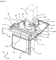
- the detection system 1 comprises an optical detection device 2 overhung by a wiping device 3.
- the optical detection device 2 comprises at least one optical surface 201 at least partially covered by a cleaning surface 202.
- the optical detection device 2 may for example be a reversing radar, a Lidar type device, an ultrasonic radar or a camera.
- the optical detection device 2 captures a plurality of data making it possible for example to create an image, to detect a distance, an angle or a position, and this by means of the optical surface 201.
- the cleaning surface 202 must therefore not be clogged, for example by impurities having settled there. It is therefore the cleaning surface 202 which is wiped by the wiping device 3.
- the wiping device 3 comprises a housing 4.
- the housing 4 defines an internal volume within which is housed a part of the wiping device 3 as will be presented subsequently.
- the housing 4 is divided into an upper portion 41 and a lower portion 42.
- the upper portion 41 and the lower portion 42 are fixed together for example by screwing a plurality of securing points 450.
- the housing 4 delimits an opening 46 extending mainly along a plane defined by a vertical axis V and a transverse axis T, i.e. along a plane parallel to the cleaning surface 202.
- a carriage 8 partially emerges from the opening 46 and mechanically carries an arm 9 and a wiper blade 10.
- the arm 9 and the wiper blade 10 extend mainly along the vertical axis V, so that the wiper blade 10 is in contact with the cleaning surface of the optical detection device 2.
- the main dimension of the wiper blade 10 is parallel to the vertical axis V and is greater than or equal to a vertical dimension according to the vertical axis V of the cleaning surface 202, so as to wipe the entirety of the latter along the vertical axis V when the wiping device 3 is in operation.
- the arm 9 may also comprise a fluid supply pipe 91 connected to a fluid reservoir, not shown here.
- the fluid supply pipe 91 may circulate up to the level of the wiper blade 10 in order to project a fluid, such as water or a cleaning fluid, against the cleaning surface 202.
- the carriage 8 is driven in a rectilinear motion parallel to the transverse axis T, from one vertical end to the other of the opening 46.
- the carriage 8 carrying the arm 9 and the wiper blade 10, the latter are therefore also driven in a rectilinear motion parallel to the transverse axis T.
- the wiper blade 10 therefore performs a back-and-forth motion against the cleaning surface 202 so as to wipe the latter.
- the opening 46 has a transverse dimension greater than a transverse dimension along the transverse axis T of the cleaning surface 202, so that the wiper blade 10 can cover the entire cleaning surface 202 when the wiping device 3 is in operation.
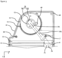
- FIG 2 is a representation of the detection system 1 identical to the figure 1 , but in the absence of the upper portion of the housing, which allows the contents of the housing to be observed. Only the lower portion 42 of the housing is visible, and comprises a plurality of interlocking members 48. The upper portion of the housing also comprises these interlocking members 48 so that the two portions of the housing can be assembled and then fixed together, for example by screwing.
- the lower portion 42 of the housing also comprises a trench 480 which extends at least partially over a periphery of the lower portion 42.
- the trench 480 is configured to cooperate, for example, with a rib of the upper portion of the housing, in order to facilitate the joining between the two portions to close the housing.
- the drive assembly 6 composed of the carriage 8, a lever 7 and a lever support 13.
- the drive assembly 6 operates a mechanical connection between the drive motor 5 and the arm 9, so that the latter is driven in a rectilinear movement from an initiation of movement of the drive motor 5.
- the lever 7 extends from the lever support 13 to the carriage 8.
- the lever 7 is able to slide in a direction relative to a main elongation axis thereof within the lever support 13.
- the lever 7 is slid into a groove 131 of the lever support 13.
- the groove 131 has dimensions adapted to the dimensions of the lever 7 so that the latter can be housed therein.
- the groove 131 extends mainly along an extension axis 135, parallel to the lever 7 and intersecting with the rotation shaft 51 of the drive motor 5.
- the cheek 510 closes the groove 131 so that the movement of the lever 7 is limited only to the sliding thereof along the groove 131.
- the lever 7 extends through a sealed blade 15 located between the lever support 13 and the carriage 8.
- the sealed blade 15 at least partially surrounds the lever support 13 and thus protects the latter from possible fluid projections that may occur during operation of the wiping device 3.
- the carriage 8 moves along the first guide 11 and the second guide 12.
- the presence of the two guides thus allows the trajectory of the rectilinear movement of the carriage 8 to be maintained, and by analogy the reliable wiping of the cleaning surface 202 by the wiping blade 10 which remains permanently positioned against the latter.
- the two guides extend so as to have a dimension parallel to the transverse axis T at least equal to a dimension parallel to the transverse axis T of the cleaning surface 202 of the detection system 1.
- the carriage 8 is able to move along the two guides in a rectilinear motion, and this without the lever 7, more particularly its rotary motion, mechanically interfering with said rectilinear motion of the carriage 8, given that the distance between the lever support 13 and the carriage 8 differs depending on the position of the latter along the two guides.
- the rotational movement of the drive motor 5 is reversible.
- the drive motor 5 may for example be a reversible drive motor 5, or include a reversibility mechanism. Since the drive motor 5 is connected to the lever support 13, the latter, as well as the lever 7, also move in a reversible rotational movement. A range of movement of the drive motor 5, the lever support 13 and the lever 7 therefore corresponds to an angular sector whose dimensions are determined as a function of the activity of the drive motor 5. Such a reversible rotational movement therefore allows the carriage 8 to move in a reversible rectilinear movement, i.e.
- the carriage 8 moves back and forth along the first guide 11 and the second guide 12 under the influence of the reversible rotary movement of the lever 7.
- the angular sector of the range of movement of the drive motor 5, the lever support 13 and the lever 7 is advantageously determined so that the carriage 8 moves over the entirety of the two guides without, however, colliding with the lower portion 42 of the housing.
- the reversible rectilinear movement of the carriage 8 therefore causes a back-and-forth movement of the wiper blade 10 against the cleaning surface 202, thus ensuring the function of the wiping device 3 within the detection system 1.
- the channel 40 extends mainly parallel to the transverse axis T and is located at the level of the trajectory of the carriage 8. Like the bulge of the upper portion of the housing, the channel 40 makes it possible to increase the space of the internal volume of the housing 4 so that a part of the carriage 8 can be arranged there and so that the carriage 8 can move without interfering with the lower portion 42 of the housing.
- FIG 3 is a perspective view of the carriage 8 and the lever 7.
- the carriage 8 extends mainly in a direction parallel to a longitudinal axis L, in order to be able to emerge from the housing through the opening as shown in the preceding figures.
- the carriage 8 comprises a bore 81 passing through the carriage 8 from one side to the other in a direction parallel to the transverse axis T.
- the bore 81 has a cylindrical shape within which a sleeve 86 is inserted.
- the sleeve 86 also has a cylindrical shape and its dimensions are such that it can be housed within the bore 81.
- the sleeve 86 has a dimension relative to the transverse axis T less than a dimension relative to the transverse axis T of the bore 81, and this in such a way that the sleeve 86 does not interfere mechanically when emerging from the bore 81.
- the sleeve 86 can be fixed in the bore 81 for example by gluing.
- the first guide can be inserted into the sleeve 86.
- the interaction between the bore 81, the sleeve 86 and the first guide then forms a sliding connection of the carriage 8.
- the sleeve 86 provides a function anti-friction, so that the carriage 8 can move along the first guide smoothly.
- the carriage 8 also comprises a notch 82 at one of its longitudinal ends, the notch 82 being juxtaposed with the bore 81.
- the notch 82 has a U shape seen in a plane LV, and an open portion of which is oriented opposite the bore 81.
- the notch 82 is configured to house the second guide visible on the figure 2 .
- the attachment between the latter and the notch 82 can be done for example by clipping.
- the notch 82 also comprises a housing 89 on one of its internal walls. The housing 89 is capable of accommodating a pad making it possible to limit the friction between the second guide and the notch 82 of the carriage 8.
- the bore 81 is interposed between the notch 82 and a hooking member 84, located at the end of the carriage 8.
- the hooking member 84 is arranged at the end emerging from the housing and has the function of supporting the arm, and of driving the latter in its rectilinear movement.
- the hooking member 84 can be of various types, the essential thing being that it ensures the maintenance of the arm without causing mechanical interference.
- the carriage 8 also comprises a pivot 85. It is via the pivot 85 that the connection between the carriage 8 and the lever 7 is made. As previously stated, it is the lever 7 that drives the carriage 8 in movement along the guides. The lever 7 therefore drives the carriage 8 via the pivot 85, while freely performing a rotational movement around it.
- the pivot 85 is advantageously arranged at the bore 81 because it is at the first guide that the movement of the carriage 8 is based.
- the carriage 8 may comprise protrusions 83.
- the protrusions 83 are for example two in number, and are arranged symmetrically with respect to a plane of symmetry of the carriage 8 parallel to the plane LV.
- the protrusions 83 are placed at a portion of the carriage 8 arranged opposite the opening of the housing and project from the carriage 8 in a direction parallel to the transverse axis T.
- the protrusions 83 are used in cooperation with the opening of the housing when the latter is equipped with a device for sealing the internal volume formed for example by a lip seal.
- the protrusions 83 make it possible to open a passage through the lip seal so that the carriage 8 can move. along the opening, and this in both directions of the rectilinear movement of the carriage 8.
- each protrusion has a conical shape allowing the lip seal to be opened progressively and smoothly.
- the movement of the carriage 8 is initiated by the lever 7.
- the connection between the lever 7 and the carriage 8 corresponds to a first variant of a first embodiment of the wiping device according to the invention.
- the lever 7 is visible on the figure 3 , in particular an end connected to the carriage 8.
- the lever 7 comprises a first longitudinal end 74 and a second longitudinal end 75.
- the first longitudinal end 74 interacts with the lever support as will be described in detail later.
- the second longitudinal end 75 interacts with the carriage 8.
- the second longitudinal end 75 of the lever 7 is provided with an orifice 72 within which the pivot 85 of the carriage 8 is inserted.
- the association between the orifice 72 of the lever 7 and the pivot 85 of the carriage 8 forms the pivot connection 78 according to the first variant of the first embodiment of the wiping device.
- the pivot connection 72 pivots freely about the pivot 85.
- the lever 7 In order for the lever 7 to be connected to the carriage 8, the lever 7 comprises a height difference 73.
- the height difference 73 has an S shape and makes it possible to adapt the vertical position of the lever 7 relative to the carriage 8 so that the pivot connection 78 can be made without mechanical interference.
- FIG 4 is a representation of the installation of the connection of the slide connection 79 according to the first variant of the first embodiment.
- the first longitudinal end 74 of the lever 7 is installed in the groove 131 of the lever support 13 in order to form the slide connection 79.
- the lever 7 is also slid through a member for setting in motion the sealed blade 15, so that the latter can follow the rotary movement of the lever 7 without mechanical interference.
- the lever 7 comprises the orifice 72 which allows the pivot connection with the carriage, not shown here.
- the groove 131 of the lever support 13 is thus closed by the cheek 510 of the drive motor 5 in order to prevent any movement along the vertical axis V of the lever 7 relative to the lever support 13.
- the rotation shaft 51 extends mainly along the vertical axis V and rotates about an axis of rotation 500.
- the drive motor 5, when the wiping device is in operation drives the lever support 13 in a rotational movement, and drives the lever 7 in movement by means of the groove 131.
- the lever 7 performs a rotary movement and also drives the sealed blade 15 in movement by means of the movement member.
- the sealed blade 15 then slides along a groove 16 created at the lower portion 42 of the housing.
- the groove 16 may for example be molded at the lower portion 42 of the housing and at least partially surrounds the lever support 13.
- the sealed blade 15 moves within the groove 16 in a movement in phase with that of the lever 7.
- the groove 16 has a length of arc of a circle greater than that of the sealed blade 15 so that the latter can have a degree of freedom within the groove 16, said degree of freedom having to be proportional to the amplitude of the rotary movement of the lever 7.
- the lever 7 moves along a movement plane 700, the latter being delimited by the main elongation axis 705 of the lever 7 and by the transverse axis T.
- the rotation axis 500 of the rotation shaft 51 of the drive motor 5 intersects the movement plane 700 of the lever 7. More precisely, the rotation axis 500 is perpendicular to the movement plane 700.
- figure 5 illustrates the mechanism of the pivot connection 78 and the slide connection 79 as a function of the position of the lever 7 and the carriage 8, seen from above, and according to the first variant of the first embodiment.
- figure 5 represents a first position where the carriage 8 is located at a transverse end of the first guide 11. 1
- the drive motor rotates the lever support 13, and by analogy the lever 7, according to a reversible rotary movement.
- the carriage 8, for its part, moves according to a reversible rectilinear movement, along the first guide 11, in particular by means of the pivot connection 78, shown in dotted lines, and which associates the orifice of the lever 7 with the pivot of the carriage 8.
- the sliding connection 79 between the lever support 13, more particularly the groove 131, and the first longitudinal end 74 of the lever 7 allows the latter to slide in the lever support 13 while the distance which separates this lever support 13 from the first guide 11 decreases. Indeed, when the carriage 8 moves along the first guide 11, the distance between the carriage 8 and the lever support 13 is variable depending on whether the carriage 8 is at a transverse end of the guides or whether it is located at an intermediate level between the transverse ends of the two guides.
- the lever 7 moves by a first sliding movement 701 in order to cover the distance between the carriage 8 and the lever support 13.
- the first sliding movement 701 is carried out in a manner oriented towards the carriage 8, under the influence of the rotary movement of the lever support 13 and the movement of the carriage 8 along the first guide 11.
- the sliding connection 79 thus allows the lever 7 to accompany the carriage 8 to the transverse ends of the guides.
- FIG 6 illustrates the drive assembly 6, still according to the first variant of the first embodiment, when the main elongation axis 705 of the lever 7 is perpendicular to the main dimension of the first guide 11.
- the main elongation axis 705 of the lever 7 extends in a direction parallel to the longitudinal axis L.
- the distance between the carriage 8 and the lever support 13 is less than that of the situation described in figure 5 , that is to say when the carriage 8 is located at one of the transverse ends of the first guide.
- the lever 7 slides in the lever support 13 by a second slide 702 oriented opposite the carriage 8.
- the lever 7 passes entirely through the lever support 13 and therefore emerges from the latter.
- the sliding connection 79 therefore allows the drive assembly 6 to drive a rectilinear movement of the arm and the wiper blade from the rotary movement of the drive motor, and this without each of the parts of the drive assembly 6, namely the lever support 13, the lever 7 and the carriage 8, mechanically interfering with each other.
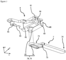
- FIG 7 represents the lever 7 and the carriage 8 according to a second variant of the first embodiment of the wiping device.
- the pivot connection 78 and the slide connection 79 are both put in place between the lever 7 and the carriage 8.
- the carriage 8 is identical to the first variant. We will therefore refer to the description of the figure 3 for detailed description of cart 8.
- the second longitudinal end 75 of the lever 7 comprises for this second variant a slot 76.
- the slot 76 is in the form of a hole having an oblong shape.
- the oblong shape of the slot 76 extends parallel to the main elongation axis 705 of the lever 7.
- the slot 76 is able to receive the pivot 85 of the carriage 8 which can be inserted therein.
- the lever 7 can pivot freely around the pivot 85 of the carriage 8.
- the oblong shape of the slot 76 of the lever 7 allows the pivot 85 to slide along the slot 76.
- the association between the pivot 85 of the carriage 8 and the slot 76 of the lever 7 forms both, according to this second variant, the pivot connection 78 and the slide connection 79.
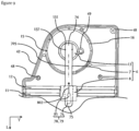
- FIGS. 8 And 9 illustrate the mechanism of the pivot connection 78 and the slide connection 79 as a function of the position of the lever 7 and the carriage 8, seen from above, and according to the second variant of the first embodiment.
- the first position where the carriage 8 is located at a transverse end of the first guide 11, is shown in figure 8 .
- the second position where the main elongation axis 705 of the lever 7 is perpendicular to the first guide 11, is shown in figure 9 .
- the first longitudinal end 74 of the lever 7 is connected to the lever support 13 by a complete connection 137.
- the complete connection 137 holds the lever 7 within the groove 131 in a completely fixed manner.
- no movement of the lever 7 is made relative to the lever support 13.
- the lever 7 is rotated by the lever support 13, and drives the carriage 8 into motion by means of the pivot connection 78 while rotating freely about the pivot 85 of the carriage 8.
- the distance between the lever support 13 and the carriage 8 increases.
- the pivot 85 slides along the slot 76 according to a first sliding direction 801, so that the carriage 8 reaches the transverse end of the first guide 11 without interference with the lever 7.
- the pivot connection 78 and the slide connection 79 are both made by the slot 76 and the pivot 85.
- the pivot connection 78 allows the lever 7 to set the carriage 8 in motion.
- the slide connection allows the pivot 85 to slide along the slot 76 so as not to create mechanical interference between the lever 7 and the carriage 8 since, unlike the first variant, the complete connection 137 fixes the lever 7 within the lever support 13.
- the drive motor 5 still comprises its rotation shaft 51 which extends along the rotation axis 500.
- the rotation axis 500 extends parallel to the transverse axis T.
- the rotation shaft 51 is in contact with a toothed wheel 21, more precisely against a slice 212 thereof, said slice 212 being provided with teeth.
- the toothed wheel 21 extends mainly along the longitudinal axis L and the transverse axis T.
- the rotation shaft 51 of the drive motor 5 may for example be a worm screw, a pitch of which has a shape complementarity with the teeth of the toothed wheel 21.
- the gear wheel 21 is also connected to a connecting rod 18.
- the connecting rod 18 has a first attachment 181, located at one end of the connecting rod 18 and connected to a face 213 of the gear wheel.
- the gear wheel 21 is rotated by the rotation shaft 51 of the drive motor 5, the first attachment 181 of the connecting rod 18 also performs a rotary movement, the latter being circular and unidirectional around a center 211 of the toothed wheel 21.
- the connecting rod 18 comprises a second attachment 182, located at the end opposite the first attachment 181.
- the second attachment 182 is connected to a drive bearing 19.
- the second attachment 182 of the connecting rod 18 drives the drive bearing 19 in an oscillating movement.
- the mechanism of the connecting rod 18 is such that, despite the unidirectional rotary movement of the toothed wheel 21 and the first attachment 181 of the connecting rod 18, the second attachment 182 of the connecting rod 18 drives the drive bearing 19 in a reversible rotary movement, i.e. an oscillation.
- the reversible rotary movement of the drive bearing 19 therefore initiates the reversible rotary movement of the lever 7 and the reversible rectilinear movement of the carriage, not shown here.
- the lever 7 still comprises the orifice 72 allowing the pivot connection to the carriage carrying the arm and the wiper blade, but also, at its opposite end, an oblong hole 71, for example passing through a vertical dimension of the lever 7 along the vertical axis V and extending mainly along the main elongation axis 705 of the lever 7.
- the drive bearing 19 comprises a crank pin 191 having dimensions adapted for its insertion into the oblong hole 71 of the lever 7.
- the crank pin 191 prevents any movement of the lever 7, with the exception of the reversible rotary movement transmitted via the drive bearing 19, and the sliding of the lever 7 along the crank pin 191.
- crank pin 191 is integral with the drive bearing 19.
- the movement of the crank pin 191 is identical to that of the drive bearing 19, namely a reversible rotary movement.
- the center of the crank pin 191 remains stationary, only its ends are in motion. In this way, the crank pin 191 drives the lever 7 in a reversible rotary movement.
- the lever 7 can, however, move along its main elongation axis 705 and thus compensate for the increase or reduction in the distance separating the carriage from the crank pin 191.
- the connection between the lever 7 and the carriage have been discussed previously in the description of the first embodiment and are transposable for this second embodiment.
- the rotary movement of the lever 7 and the rectilinear movement of the carriage do not interfere with each other thanks to the sliding of the lever 7 along the crank pin 191.
- an amplitude of the rotary movement of the lever 7 is dependent on the size of a diameter of the toothed wheel 21, but also on the distance between the first attachment 181 of the connecting rod 18 and the center 211 of the toothed wheel 21.
- the lever 7 is set in motion according to the movement plane 700, which here is parallel and not intersecting the axis of rotation 500 of the rotation shaft 51 of the drive motor 5.
- the drive assembly 6 is therefore composed of the toothed wheel 21, the connecting rod 18, the drive bearing 19, the latter comprising the crank pin 191, the lever 7 and the carriage.
- This second embodiment makes it possible, from a unidirectional rotary movement of the rotation shaft 51 of the drive motor 5, to transmit a rectilinear back-and-forth movement to the wiper blade, so that the latter can perform its wiping function against the cleaning surface of the detection system.
- the invention achieves the goal it set for itself, and makes it possible to propose a wiping device equipped with a drive motor and a drive assembly comprising a pivot connection and a sliding connection making it possible to convert a rotary movement into a rectilinear movement without mechanical interference.
- Variants not described here could be implemented without departing from the context of the invention, provided that, in accordance with the invention, they comprise a wiping device in accordance with the invention.
Landscapes
- Engineering & Computer Science (AREA)
- Physics & Mathematics (AREA)
- General Physics & Mathematics (AREA)
- Computer Networks & Wireless Communication (AREA)
- Radar, Positioning & Navigation (AREA)
- Remote Sensing (AREA)
- Mechanical Engineering (AREA)
- Electromagnetism (AREA)
- Optics & Photonics (AREA)
- Transmission Devices (AREA)
- Ink Jet (AREA)
- Optical Measuring Cells (AREA)
Claims (12)
- Wischvorrichtung (3) für ein Detektionssystem (1) eines Fahrzeugs, welches einen Arm (9), ein Wischblatt (10), einen Antriebsmotor (5) des Armes (9) und eine Antriebsanordnung (6), die einen geradlinig beweglichen Schlitten (8) aufweist und den Antriebsmotor (5) und den Arm (9) verbindet, umfasst, wobei der Arm (9) von dem Schlitten (8) getragen wird, dadurch gekennzeichnet, dass die Antriebsanordnung (6) mindestens eine Schwenkverbindung (78) und mindestens eine Gleitverbindung (79) umfasst, die zwischen dem Antriebsmotor (5) und dem Arm (9) angeordnet sind, und dadurch, dass die Antriebsanordnung (6) mindestens einen Hebel (7) umfasst, wobei die Schwenkverbindung (78) zwischen dem Hebel (7) und dem Schlitten (8) angeordnet ist.
- Wischvorrichtung (3) nach Anspruch 1, wobei die Gleitverbindung (79) zwischen dem Antriebsmotor (5) und dem Hebel (7) angeordnet ist.
- Wischvorrichtung (3) nach Anspruch 2, wobei die Antriebsanordnung (6) mindestens einen Hebelträger (13) umfasst, der mit einer Drehwelle (51) des Antriebsmotors (5) drehfest verbunden ist, wobei der Hebel (7) ein erstes Längsende (74) umfasst, wobei die Gleitverbindung (79) durch ein Gleiten des ersten Längsendes (74) bezüglich des Hebelträgers (13) hergestellt wird.
- Wischvorrichtung nach Anspruch 3, wobei der Hebelträger (13) eine Nut (131) umfasst, in der das erste Längsende (74) des Hebels (7) aufgenommen ist, wobei sich die Nut (131) entlang einer Erstreckungsachse (135) erstreckt, die sich mit einer Drehachse (500) der Drehwelle (51) des Antriebsmotors (5) schneidet.
- Wischvorrichtung (3) nach Anspruch 4, wobei die Drehwelle (51) des Antriebsmotors (5) eine Wange (510) umfasst, welche mit dem Hebelträger (13) fest verbunden ist und welche die Nut (131) verschließt.
- Wischvorrichtung (3) nach Anspruch 1, wobei die Gleitverbindung (79) zwischen dem Schlitten (8) und dem Hebel (7) angeordnet ist.
- Wischvorrichtung (3) nach Anspruch 6, wobei die Antriebsanordnung (6) einen Hebelträger (13) umfasst, wobei der Hebel (7) mit dem Hebelträger (13) durch eine vollständige Verbindung (137) verbunden ist.
- Wischvorrichtung (3) nach Anspruch 6 oder 7, wobei der Schlitten (8) einen Drehzapfen (85) umfasst, wobei der Hebel (7) ein zweites Längsende (75) umfasst, das einen Schlitz (76) aufweist, wobei die Gleitverbindung (79) und die Schwenkverbindung (78) durch ein Gleiten und eine Drehung des zweiten Längsendes (75) bezüglich des Drehzapfens (85) hergestellt werden.
- Wischvorrichtung (3) nach Anspruch 1, wobei die Antriebsanordnung (6) mindestens ein Zahnrad (21), das von einer Drehwelle (51) des Antriebsmotors (5) in Bewegung versetzt wird, eine von dem Zahnrad (21) angetriebene Schubstange (18) und ein Antriebslager (19), das von der Schubstange (18) in Bewegung versetzt wird und das den Hebel (7) antreibt, umfasst.
- Wischvorrichtung (3) nach Anspruch 9, wobei das Antriebslager (19) einen Zapfen (191) umfasst, der in einem am Hebel (7) ausgebildeten Langloch (71) aufgenommen ist.
- Wischvorrichtung (3) nach einem der vorhergehenden Ansprüche, wobei der Schlitten (8) dafür ausgelegt ist, sich geradlinig auf einer Führung (11, 12) zu bewegen.
- Detektionssystem (1) eines Fahrzeugs, das eine optische Detektionsvorrichtung (2) und eine Wischvorrichtung (3) nach einem der vorhergehenden Ansprüche umfasst.
Applications Claiming Priority (2)
| Application Number | Priority Date | Filing Date | Title |
|---|---|---|---|
| FR1914740A FR3105134B1 (fr) | 2019-12-18 | 2019-12-18 | Dispositif d’essuyage pour système de détection |
| PCT/EP2020/081840 WO2021121791A1 (fr) | 2019-12-18 | 2020-11-12 | Dispositif d'essuyage pour système de détection |
Publications (2)
| Publication Number | Publication Date |
|---|---|
| EP4172008A1 EP4172008A1 (de) | 2023-05-03 |
| EP4172008B1 true EP4172008B1 (de) | 2024-10-02 |
Family
ID=69700194
Family Applications (1)
| Application Number | Title | Priority Date | Filing Date |
|---|---|---|---|
| EP20803568.3A Active EP4172008B1 (de) | 2019-12-18 | 2020-11-12 | Wischvorrichtung für ein detektionssystem |
Country Status (6)
| Country | Link |
|---|---|
| EP (1) | EP4172008B1 (de) |
| JP (1) | JP7527375B2 (de) |
| KR (1) | KR20220111714A (de) |
| CN (1) | CN114845908B (de) |
| FR (1) | FR3105134B1 (de) |
| WO (1) | WO2021121791A1 (de) |
Families Citing this family (5)
| Publication number | Priority date | Publication date | Assignee | Title |
|---|---|---|---|---|
| KR20240032564A (ko) | 2022-09-02 | 2024-03-12 | 주식회사 엘지에너지솔루션 | 증점제 분산액, 이를 포함하는 음극 슬러리, 음극 및 리튬 이차전지 |
| CN116168484A (zh) * | 2023-02-24 | 2023-05-26 | 华能伊敏煤电有限责任公司 | 一种门禁系统的面部识别面板结构 |
| DE102023202746A1 (de) * | 2023-03-27 | 2024-10-02 | Robert Bosch Gesellschaft mit beschränkter Haftung | LiDAR-Reinigungssystem |
| EP4442519A1 (de) * | 2023-04-05 | 2024-10-09 | Inalfa Roof Systems Group B.V. | Fahrzeugdachmodul für einen sensor |
| DE102023115540A1 (de) * | 2023-06-14 | 2024-12-19 | Valeo Systèmes d'Éssuyage SAS | Reinigungseinrichtung für eine Umfelderkennungsvorrichtung |
Citations (4)
| Publication number | Priority date | Publication date | Assignee | Title |
|---|---|---|---|---|
| CN107578680A (zh) * | 2017-10-16 | 2018-01-12 | 牡丹江师范学院 | 一种用于电磁学教学的实验设备 |
| CN108196480A (zh) * | 2017-12-30 | 2018-06-22 | 长沙智能驾驶研究院有限公司 | 智能车辆的传感器的防护罩及智能车辆的监测电子设备 |
| US20180215350A1 (en) * | 2017-01-27 | 2018-08-02 | SMR Patents S.à.r.l. | Wiping device for an optical device and a rear view device for a motor vehicle with same |
| DE102017221530A1 (de) * | 2017-11-30 | 2019-06-06 | Robert Bosch Gmbh | Vorrichtung ausgebildet zur Umfelderfassung und Verfahren zur Reinigung einer Abdeckung einer solchen Vorrichtung |
Family Cites Families (9)
| Publication number | Priority date | Publication date | Assignee | Title |
|---|---|---|---|---|
| JPS5182240U (de) * | 1974-12-24 | 1976-07-01 | ||
| JPS544773Y2 (de) * | 1976-11-18 | 1979-02-28 | ||
| US5274876A (en) * | 1992-02-12 | 1994-01-04 | Wehrspann John H | Universal windshield wiper mechanism |
| JPH11142514A (ja) * | 1997-11-05 | 1999-05-28 | Hitachi Ltd | 車載用レーダシステム |
| DE102013213415A1 (de) | 2013-07-09 | 2015-01-15 | Continental Teves Ag & Co. Ohg | Optische Überwachungseinrichtung für ein Kraftfahrzeug, insbesondere Überwachungskamera mit einer optisch transparenten Abdeckung |
| US11034335B2 (en) * | 2016-07-07 | 2021-06-15 | Nio Usa, Inc. | Low-profile imaging system with enhanced viewing angles |
| FR3056526B1 (fr) * | 2016-09-28 | 2018-10-26 | Valeo Systemes D'essuyage | Dispositif de nettoyage destine a projeter au moins un fluide vers une surface a nettoyer d'un vehicule automobile |
| CN107413691A (zh) * | 2017-06-30 | 2017-12-01 | 广东科学技术职业学院 | 一种自动除尘装置及其工作方法、太阳能装置 |
| CN108583453B (zh) * | 2018-06-28 | 2021-02-19 | 北京图森智途科技有限公司 | 一种传感器安装装置 |
-
2019
- 2019-12-18 FR FR1914740A patent/FR3105134B1/fr active Active
-
2020
- 2020-11-12 WO PCT/EP2020/081840 patent/WO2021121791A1/fr not_active Ceased
- 2020-11-12 KR KR1020227024352A patent/KR20220111714A/ko not_active Ceased
- 2020-11-12 JP JP2022537526A patent/JP7527375B2/ja active Active
- 2020-11-12 CN CN202080088992.1A patent/CN114845908B/zh active Active
- 2020-11-12 EP EP20803568.3A patent/EP4172008B1/de active Active
Patent Citations (4)
| Publication number | Priority date | Publication date | Assignee | Title |
|---|---|---|---|---|
| US20180215350A1 (en) * | 2017-01-27 | 2018-08-02 | SMR Patents S.à.r.l. | Wiping device for an optical device and a rear view device for a motor vehicle with same |
| CN107578680A (zh) * | 2017-10-16 | 2018-01-12 | 牡丹江师范学院 | 一种用于电磁学教学的实验设备 |
| DE102017221530A1 (de) * | 2017-11-30 | 2019-06-06 | Robert Bosch Gmbh | Vorrichtung ausgebildet zur Umfelderfassung und Verfahren zur Reinigung einer Abdeckung einer solchen Vorrichtung |
| CN108196480A (zh) * | 2017-12-30 | 2018-06-22 | 长沙智能驾驶研究院有限公司 | 智能车辆的传感器的防护罩及智能车辆的监测电子设备 |
Also Published As
| Publication number | Publication date |
|---|---|
| WO2021121791A1 (fr) | 2021-06-24 |
| FR3105134B1 (fr) | 2023-06-30 |
| JP7527375B2 (ja) | 2024-08-02 |
| FR3105134A1 (fr) | 2021-06-25 |
| CN114845908A (zh) | 2022-08-02 |
| JP2023506964A (ja) | 2023-02-20 |
| EP4172008A1 (de) | 2023-05-03 |
| KR20220111714A (ko) | 2022-08-09 |
| CN114845908B (zh) | 2025-12-05 |
Similar Documents
| Publication | Publication Date | Title |
|---|---|---|
| EP4172008B1 (de) | Wischvorrichtung für ein detektionssystem | |
| EP4065435B1 (de) | Verfahren zur reinigung einer verglasten oberfläche eines kraftfahrzeugs | |
| EP3184379B1 (de) | Kappe und antriebsarm für eine reinigungsvorrichtung eines kraftfahrzeugs | |
| EP3231673A1 (de) | Reinigungssystem der windschutzscheibe eines fahrzeugs | |
| FR3105133A1 (fr) | Dispositif d’essuyage pour système de détection | |
| FR3105135A1 (fr) | Dispositif d’essuyage pour système de détection | |
| EP4028292A1 (de) | Kurbelzapfen, kugelgelenk und entsprechendes scheibenwischerbetätigungsgestängesystem und verfahren zu dessen zusammenbau | |
| WO2007093545A1 (fr) | Mécanisme de commande en rotation notamment pour dispositif d'essuyage de véhicule automobile. | |
| FR2907733A1 (fr) | Systeme d'essuyage pour pare-brise de vehicule automobile | |
| EP1717118B1 (de) | Scheibenwischer | |
| EP3658416B1 (de) | Hintere bilderfassungsvorrichtung für ein kraftfahrzeug | |
| FR2887831A1 (fr) | Mecanisme de conversion d'un mouvement de rotation permettant une reduction d'amplitude angulaire et dispositif d'essuyage incorporant un tel mecanisme | |
| WO2006117082A1 (fr) | Essuie-glace de type pantographe dote d'un balai d'essuyage a angle d'attaque variable | |
| EP3523164B1 (de) | Zahnrad für einen getriebemotor eines scheibenwischers | |
| FR2981030A1 (fr) | Support de commande pour systeme d'entrainement de balai d'essuyage et systeme d'entrainement associe | |
| FR3030410A1 (fr) | Capot pour un bras d'essuie-glace | |
| FR2918023A1 (fr) | Dispositif de commande du dephasage des mouvements de deux balais d'un essuie-glace de vehicule automobile | |
| FR2775495A1 (fr) | Dispositif de manoeuvre d'un vantail de porte de vehicule a encombrement reduit | |
| FR2970221A1 (fr) | Dispositif d'essuie-glace, notamment pour vehicule automobile | |
| FR2761319A1 (fr) | Systeme d'essuyage comportant un motoreducteur fixe sur une traverse, notamment pour vehicules automobiles | |
| FR2885104A1 (fr) | Bras d'essuie-glace a cinematique pantographe | |
| FR3023766A1 (fr) | Systeme d'embiellage a engrenage pour un motoreducteur d'essuie-glace | |
| FR2907734A1 (fr) | Mecanisme de bras porte-balai rotatif pour dispositif d'essuie-glace | |
| FR2910413A1 (fr) | Systeme d'essuyage pour vitre de vehicule automobile | |
| FR2890624A1 (fr) | Dispositif d'essuyage a balayage elliptique |
Legal Events
| Date | Code | Title | Description |
|---|---|---|---|
| STAA | Information on the status of an ep patent application or granted ep patent |
Free format text: STATUS: UNKNOWN |
|
| STAA | Information on the status of an ep patent application or granted ep patent |
Free format text: STATUS: THE INTERNATIONAL PUBLICATION HAS BEEN MADE |
|
| PUAI | Public reference made under article 153(3) epc to a published international application that has entered the european phase |
Free format text: ORIGINAL CODE: 0009012 |
|
| STAA | Information on the status of an ep patent application or granted ep patent |
Free format text: STATUS: REQUEST FOR EXAMINATION WAS MADE |
|
| 17P | Request for examination filed |
Effective date: 20220601 |
|
| AK | Designated contracting states |
Kind code of ref document: A1 Designated state(s): AL AT BE BG CH CY CZ DE DK EE ES FI FR GB GR HR HU IE IS IT LI LT LU LV MC MK MT NL NO PL PT RO RS SE SI SK SM TR |
|
| DAV | Request for validation of the european patent (deleted) | ||
| DAX | Request for extension of the european patent (deleted) | ||
| GRAP | Despatch of communication of intention to grant a patent |
Free format text: ORIGINAL CODE: EPIDOSNIGR1 |
|
| STAA | Information on the status of an ep patent application or granted ep patent |
Free format text: STATUS: GRANT OF PATENT IS INTENDED |
|
| INTG | Intention to grant announced |
Effective date: 20240429 |
|
| GRAS | Grant fee paid |
Free format text: ORIGINAL CODE: EPIDOSNIGR3 |
|
| GRAA | (expected) grant |
Free format text: ORIGINAL CODE: 0009210 |
|
| STAA | Information on the status of an ep patent application or granted ep patent |
Free format text: STATUS: THE PATENT HAS BEEN GRANTED |
|
| AK | Designated contracting states |
Kind code of ref document: B1 Designated state(s): AL AT BE BG CH CY CZ DE DK EE ES FI FR GB GR HR HU IE IS IT LI LT LU LV MC MK MT NL NO PL PT RO RS SE SI SK SM TR |
|
| REG | Reference to a national code |
Ref country code: GB Ref legal event code: FG4D Free format text: NOT ENGLISH |
|
| REG | Reference to a national code |
Ref country code: CH Ref legal event code: EP |
|
| REG | Reference to a national code |
Ref country code: IE Ref legal event code: FG4D Free format text: LANGUAGE OF EP DOCUMENT: FRENCH |
|
| REG | Reference to a national code |
Ref country code: DE Ref legal event code: R096 Ref document number: 602020038769 Country of ref document: DE |
|
| REG | Reference to a national code |
Ref country code: LT Ref legal event code: MG9D |
|
| REG | Reference to a national code |
Ref country code: NL Ref legal event code: MP Effective date: 20241002 |
|
| REG | Reference to a national code |
Ref country code: AT Ref legal event code: MK05 Ref document number: 1728252 Country of ref document: AT Kind code of ref document: T Effective date: 20241002 |
|
| PG25 | Lapsed in a contracting state [announced via postgrant information from national office to epo] |
Ref country code: NL Free format text: LAPSE BECAUSE OF FAILURE TO SUBMIT A TRANSLATION OF THE DESCRIPTION OR TO PAY THE FEE WITHIN THE PRESCRIBED TIME-LIMIT Effective date: 20241002 |
|
| PG25 | Lapsed in a contracting state [announced via postgrant information from national office to epo] |
Ref country code: NL Free format text: LAPSE BECAUSE OF FAILURE TO SUBMIT A TRANSLATION OF THE DESCRIPTION OR TO PAY THE FEE WITHIN THE PRESCRIBED TIME-LIMIT Effective date: 20241002 |
|
| PG25 | Lapsed in a contracting state [announced via postgrant information from national office to epo] |
Ref country code: HR Free format text: LAPSE BECAUSE OF FAILURE TO SUBMIT A TRANSLATION OF THE DESCRIPTION OR TO PAY THE FEE WITHIN THE PRESCRIBED TIME-LIMIT Effective date: 20241002 Ref country code: PT Free format text: LAPSE BECAUSE OF FAILURE TO SUBMIT A TRANSLATION OF THE DESCRIPTION OR TO PAY THE FEE WITHIN THE PRESCRIBED TIME-LIMIT Effective date: 20250203 Ref country code: IS Free format text: LAPSE BECAUSE OF FAILURE TO SUBMIT A TRANSLATION OF THE DESCRIPTION OR TO PAY THE FEE WITHIN THE PRESCRIBED TIME-LIMIT Effective date: 20250202 |
|
| PG25 | Lapsed in a contracting state [announced via postgrant information from national office to epo] |
Ref country code: FI Free format text: LAPSE BECAUSE OF FAILURE TO SUBMIT A TRANSLATION OF THE DESCRIPTION OR TO PAY THE FEE WITHIN THE PRESCRIBED TIME-LIMIT Effective date: 20241002 |
|
| PG25 | Lapsed in a contracting state [announced via postgrant information from national office to epo] |
Ref country code: BG Free format text: LAPSE BECAUSE OF FAILURE TO SUBMIT A TRANSLATION OF THE DESCRIPTION OR TO PAY THE FEE WITHIN THE PRESCRIBED TIME-LIMIT Effective date: 20241002 |
|
| PG25 | Lapsed in a contracting state [announced via postgrant information from national office to epo] |
Ref country code: ES Free format text: LAPSE BECAUSE OF FAILURE TO SUBMIT A TRANSLATION OF THE DESCRIPTION OR TO PAY THE FEE WITHIN THE PRESCRIBED TIME-LIMIT Effective date: 20241002 |
|
| PG25 | Lapsed in a contracting state [announced via postgrant information from national office to epo] |
Ref country code: NO Free format text: LAPSE BECAUSE OF FAILURE TO SUBMIT A TRANSLATION OF THE DESCRIPTION OR TO PAY THE FEE WITHIN THE PRESCRIBED TIME-LIMIT Effective date: 20250102 |
|
| PG25 | Lapsed in a contracting state [announced via postgrant information from national office to epo] |
Ref country code: GR Free format text: LAPSE BECAUSE OF FAILURE TO SUBMIT A TRANSLATION OF THE DESCRIPTION OR TO PAY THE FEE WITHIN THE PRESCRIBED TIME-LIMIT Effective date: 20250103 Ref country code: LV Free format text: LAPSE BECAUSE OF FAILURE TO SUBMIT A TRANSLATION OF THE DESCRIPTION OR TO PAY THE FEE WITHIN THE PRESCRIBED TIME-LIMIT Effective date: 20241002 Ref country code: AT Free format text: LAPSE BECAUSE OF FAILURE TO SUBMIT A TRANSLATION OF THE DESCRIPTION OR TO PAY THE FEE WITHIN THE PRESCRIBED TIME-LIMIT Effective date: 20241002 |
|
| PG25 | Lapsed in a contracting state [announced via postgrant information from national office to epo] |
Ref country code: PL Free format text: LAPSE BECAUSE OF FAILURE TO SUBMIT A TRANSLATION OF THE DESCRIPTION OR TO PAY THE FEE WITHIN THE PRESCRIBED TIME-LIMIT Effective date: 20241002 Ref country code: CZ Free format text: LAPSE BECAUSE OF FAILURE TO SUBMIT A TRANSLATION OF THE DESCRIPTION OR TO PAY THE FEE WITHIN THE PRESCRIBED TIME-LIMIT Effective date: 20241002 |
|
| PG25 | Lapsed in a contracting state [announced via postgrant information from national office to epo] |
Ref country code: RS Free format text: LAPSE BECAUSE OF FAILURE TO SUBMIT A TRANSLATION OF THE DESCRIPTION OR TO PAY THE FEE WITHIN THE PRESCRIBED TIME-LIMIT Effective date: 20250102 |
|
| REG | Reference to a national code |
Ref country code: CH Ref legal event code: PL |
|
| PG25 | Lapsed in a contracting state [announced via postgrant information from national office to epo] |
Ref country code: SM Free format text: LAPSE BECAUSE OF FAILURE TO SUBMIT A TRANSLATION OF THE DESCRIPTION OR TO PAY THE FEE WITHIN THE PRESCRIBED TIME-LIMIT Effective date: 20241002 |
|
| REG | Reference to a national code |
Ref country code: DE Ref legal event code: R097 Ref document number: 602020038769 Country of ref document: DE |
|
| PG25 | Lapsed in a contracting state [announced via postgrant information from national office to epo] |
Ref country code: MC Free format text: LAPSE BECAUSE OF FAILURE TO SUBMIT A TRANSLATION OF THE DESCRIPTION OR TO PAY THE FEE WITHIN THE PRESCRIBED TIME-LIMIT Effective date: 20241002 |
|
| PG25 | Lapsed in a contracting state [announced via postgrant information from national office to epo] |
Ref country code: DK Free format text: LAPSE BECAUSE OF FAILURE TO SUBMIT A TRANSLATION OF THE DESCRIPTION OR TO PAY THE FEE WITHIN THE PRESCRIBED TIME-LIMIT Effective date: 20241002 |
|
| PG25 | Lapsed in a contracting state [announced via postgrant information from national office to epo] |
Ref country code: LU Free format text: LAPSE BECAUSE OF NON-PAYMENT OF DUE FEES Effective date: 20241112 |
|
| REG | Reference to a national code |
Ref country code: CH Ref legal event code: PL |
|
| PG25 | Lapsed in a contracting state [announced via postgrant information from national office to epo] |
Ref country code: EE Free format text: LAPSE BECAUSE OF FAILURE TO SUBMIT A TRANSLATION OF THE DESCRIPTION OR TO PAY THE FEE WITHIN THE PRESCRIBED TIME-LIMIT Effective date: 20241002 |
|
| PG25 | Lapsed in a contracting state [announced via postgrant information from national office to epo] |
Ref country code: CH Free format text: LAPSE BECAUSE OF NON-PAYMENT OF DUE FEES Effective date: 20241130 |
|
| PG25 | Lapsed in a contracting state [announced via postgrant information from national office to epo] |
Ref country code: RO Free format text: LAPSE BECAUSE OF FAILURE TO SUBMIT A TRANSLATION OF THE DESCRIPTION OR TO PAY THE FEE WITHIN THE PRESCRIBED TIME-LIMIT Effective date: 20241002 |
|
| PG25 | Lapsed in a contracting state [announced via postgrant information from national office to epo] |
Ref country code: SK Free format text: LAPSE BECAUSE OF FAILURE TO SUBMIT A TRANSLATION OF THE DESCRIPTION OR TO PAY THE FEE WITHIN THE PRESCRIBED TIME-LIMIT Effective date: 20241002 |
|
| PG25 | Lapsed in a contracting state [announced via postgrant information from national office to epo] |
Ref country code: IT Free format text: LAPSE BECAUSE OF FAILURE TO SUBMIT A TRANSLATION OF THE DESCRIPTION OR TO PAY THE FEE WITHIN THE PRESCRIBED TIME-LIMIT Effective date: 20241002 |
|
| PLBE | No opposition filed within time limit |
Free format text: ORIGINAL CODE: 0009261 |
|
| STAA | Information on the status of an ep patent application or granted ep patent |
Free format text: STATUS: NO OPPOSITION FILED WITHIN TIME LIMIT |
|
| REG | Reference to a national code |
Ref country code: BE Ref legal event code: MM Effective date: 20241130 |
|
| PG25 | Lapsed in a contracting state [announced via postgrant information from national office to epo] |
Ref country code: SE Free format text: LAPSE BECAUSE OF FAILURE TO SUBMIT A TRANSLATION OF THE DESCRIPTION OR TO PAY THE FEE WITHIN THE PRESCRIBED TIME-LIMIT Effective date: 20241002 |
|
| 26N | No opposition filed |
Effective date: 20250703 |
|
| GBPC | Gb: european patent ceased through non-payment of renewal fee |
Effective date: 20250102 |
|
| PG25 | Lapsed in a contracting state [announced via postgrant information from national office to epo] |
Ref country code: BE Free format text: LAPSE BECAUSE OF NON-PAYMENT OF DUE FEES Effective date: 20241130 Ref country code: GB Free format text: LAPSE BECAUSE OF NON-PAYMENT OF DUE FEES Effective date: 20250102 |
|
| PG25 | Lapsed in a contracting state [announced via postgrant information from national office to epo] |
Ref country code: IE Free format text: LAPSE BECAUSE OF NON-PAYMENT OF DUE FEES Effective date: 20241112 |
|
| PGFP | Annual fee paid to national office [announced via postgrant information from national office to epo] |
Ref country code: DE Payment date: 20251117 Year of fee payment: 6 |
|
| PGFP | Annual fee paid to national office [announced via postgrant information from national office to epo] |
Ref country code: FR Payment date: 20251128 Year of fee payment: 6 |
|
| PG25 | Lapsed in a contracting state [announced via postgrant information from national office to epo] |
Ref country code: HU Free format text: LAPSE BECAUSE OF FAILURE TO SUBMIT A TRANSLATION OF THE DESCRIPTION OR TO PAY THE FEE WITHIN THE PRESCRIBED TIME-LIMIT; INVALID AB INITIO Effective date: 20201112 |
|
| PG25 | Lapsed in a contracting state [announced via postgrant information from national office to epo] |
Ref country code: CY Free format text: LAPSE BECAUSE OF FAILURE TO SUBMIT A TRANSLATION OF THE DESCRIPTION OR TO PAY THE FEE WITHIN THE PRESCRIBED TIME-LIMIT; INVALID AB INITIO Effective date: 20201112 |