EP4171996B1 - Anhängersystem, verfahren zum transport eines objekts durch ein anhängersystem und anhängerhebersystem - Google Patents
Anhängersystem, verfahren zum transport eines objekts durch ein anhängersystem und anhängerhebersystem Download PDFInfo
- Publication number
- EP4171996B1 EP4171996B1 EP21736323.3A EP21736323A EP4171996B1 EP 4171996 B1 EP4171996 B1 EP 4171996B1 EP 21736323 A EP21736323 A EP 21736323A EP 4171996 B1 EP4171996 B1 EP 4171996B1
- Authority
- EP
- European Patent Office
- Prior art keywords
- jack
- loading bed
- trailer
- trailer module
- connector
- Prior art date
- Legal status (The legal status is an assumption and is not a legal conclusion. Google has not performed a legal analysis and makes no representation as to the accuracy of the status listed.)
- Active
Links
Images

Classifications
-
- B—PERFORMING OPERATIONS; TRANSPORTING
- B60—VEHICLES IN GENERAL
- B60P—VEHICLES ADAPTED FOR LOAD TRANSPORTATION OR TO TRANSPORT, TO CARRY, OR TO COMPRISE SPECIAL LOADS OR OBJECTS
- B60P3/00—Vehicles adapted to transport, to carry or to comprise special loads or objects
- B60P3/40—Vehicles adapted to transport, to carry or to comprise special loads or objects for carrying long loads, e.g. with separate wheeled load supporting elements
-
- B—PERFORMING OPERATIONS; TRANSPORTING
- B60—VEHICLES IN GENERAL
- B60P—VEHICLES ADAPTED FOR LOAD TRANSPORTATION OR TO TRANSPORT, TO CARRY, OR TO COMPRISE SPECIAL LOADS OR OBJECTS
- B60P1/00—Vehicles predominantly for transporting loads and modified to facilitate loading, consolidating the load, or unloading
- B60P1/02—Vehicles predominantly for transporting loads and modified to facilitate loading, consolidating the load, or unloading with parallel up-and-down movement of load supporting or containing element
-
- B—PERFORMING OPERATIONS; TRANSPORTING
- B62—LAND VEHICLES FOR TRAVELLING OTHERWISE THAN ON RAILS
- B62D—MOTOR VEHICLES; TRAILERS
- B62D59/00—Trailers with driven ground wheels or the like
- B62D59/04—Trailers with driven ground wheels or the like driven from propulsion unit on trailer
-
- B—PERFORMING OPERATIONS; TRANSPORTING
- B62—LAND VEHICLES FOR TRAVELLING OTHERWISE THAN ON RAILS
- B62D—MOTOR VEHICLES; TRAILERS
- B62D63/00—Motor vehicles or trailers not otherwise provided for
- B62D63/02—Motor vehicles
- B62D63/025—Modular vehicles
-
- B—PERFORMING OPERATIONS; TRANSPORTING
- B62—LAND VEHICLES FOR TRAVELLING OTHERWISE THAN ON RAILS
- B62D—MOTOR VEHICLES; TRAILERS
- B62D63/00—Motor vehicles or trailers not otherwise provided for
- B62D63/06—Trailers
- B62D63/068—Trailers with more than two axles or more than four wheels
-
- B—PERFORMING OPERATIONS; TRANSPORTING
- B66—HOISTING; LIFTING; HAULING
- B66F—HOISTING, LIFTING, HAULING OR PUSHING, NOT OTHERWISE PROVIDED FOR, e.g. DEVICES WHICH APPLY A LIFTING OR PUSHING FORCE DIRECTLY TO THE SURFACE OF A LOAD
- B66F1/00—Devices, e.g. jacks, for lifting loads in predetermined steps
- B66F1/02—Devices, e.g. jacks, for lifting loads in predetermined steps with locking elements, e.g. washers, co-operating with posts
Definitions
- the invention pertains to a trailer system, a method for moving an object by a trailer system and a trailer jack system.
- Modular trailer systems may comprise multiple trailer modules.
- Each trailer module comprises a plurality of wheels, which in many cases can be individually controlled so that the trailer module can move over the surface in any desired direction, including sideways and around its own central axis.
- Each trailer module further comprises a load bed, for supporting an object to be moved. The object can be placed directly on the loading bed, and/or be supported by object supports which are in turn supported by the loading bed.
- the trailer modules can be connected to each other in longitudinal and/or transverse directions to obtain a combined loading bed, which is larger than the loading bed of an individual trailer module.
- the combined loading bed is rigid in order to maintain stability of the load. So, the loading beds of individual modules do for example not hinge relative to each other. This is also not necessary, because the wheels of the trailer modules often can be individually controlled and rotated individually about both a horizontal and a vertical axis.
- the trailer modules can also be used individually, when the size and weight of the object to be transported allows this. Examples of such modular trailer systems are known e.g. from DE 20 2014 004907 U1 , EP 2 974 905 A1 or US 2018/339736 A1 .
- the loading bed of a trailer module or the combined loading bed of multiple mutually connected trailer modules is arranged below the object.
- the object may need to be lifted and put on temporary ground supports in order to allow this.
- the object is then lowered onto the loading bed or onto loading bed supports on the loading bed of the trailer module(s) in order to prepare the object for transport.
- the loading bed supports may be static or may be moveable, e.g. in the form of jacks.
- the loading bed of a trailer module can be moved in vertical direction over a limited stroke, e.g. 600 mm. In that case, the loading bed can be moved upwards to a limited extent to lift the object away from the temporary ground supports, so the object can be fully supported on the loading bed of the trailer module or trailer modules and the temporary ground supports can be removed.
- this approach requires a lot of time, labour and materials, in particular support materials.
- the large amount of materials that are required means that more transport of goods to the site where the object is located is required, which increases the COz-footprint of the transport project.
- this increases the overall height of the trailer system, which results in that more free space is needed below the object in order to arrange the trailer module below it. Also it may affect the stability of the trailer system when to object has to be engaged at a significant height, because this results in a high centre of gravity.
- the object of the invention is obtained by a trailer system in accordance with claim 1.
- the trailer system comprises a first trailer module.
- the first trailer module is for example a trailer module of a self-propelled modular trailer system, or a trailer module which can be connected to a truck.
- the first trailer module comprises a plurality of wheels.
- the wheels - and optionally all of the wheels - are rotatable around a horizontal axis and also pivotable or rotatable around a vertical axis.
- the position of each wheel around its vertical axis of rotation can be controlled individually, so that the first trailer module is able to move over the surface in all directions onto which it is located.
- the rotational speed of each wheel around its horizontal axis of rotation can be controlled individually.
- the wheels are grouped in pairs, and the rotation around the horizontal axis and/or around the vertical axis is controlled per pair of wheels.
- the first trailer module comprises one or more groups of wheels which are provided with one or more tracks.
- the first trailer module further comprises a loading bed. Objects to be transported are to be arranged on the loading bed, either directly or on loading bed supports which are arranged on the loading bed.
- the loading bed has an upper surface.
- the first trailer module further comprises a primary loading bed connector for rigidly connecting the loading bed of the first trailer module to a loading bed of a further trailer module to form a combined rigid loading bed.
- the primary loading bed connector is arranged below an upper surface of the loading bed of the first trailer module.
- the first trailer module does not have to be connected to a further trailer module in order to practice the current invention.
- the trailer system according to the invention further comprises a first jack system.
- the first jack system comprises a first jack cradle.
- the jack cradle comprises a jack holder and a jack.
- the jack is accommodated in the jack holder.
- the jack cradle further comprises a primary cradle connector, which is connected to the primary loading bed connector of the first trailer module. Therewith the primary cradle connector connects the first jack cradle to the first trailer module. So, a connector that is provided on the first trailer module to in other uses of the first trailer module connect the first trailer module to a further trailer, is in accordance with the invention used to instead connect the first trailer module to the first jack cradle.
- the jack holder of the first jack cradle extends at least partly below the upper surface of the loading bed of the of the first trailer module.
- the jack holder of the first jack cradle extends entirely below the upper surface of the loading bed of the of the first trailer module.
- the jack holder extends at least partly below the primary cradle connector.
- the jack holder extends fully below the primary cradle connector.
- the jack extends at least partly below the extends at least partly below the upper surface of the loading bed of the of the first trailer module and/or the primary cradle connector.
- the jack extends fully below the extends at least partly below the upper surface of the loading bed of the of the first trailer module and/or the primary cradle connector.
- the jack of the jack system is or forms part of a jack as disclosed in N L 1042448.
- the loading bed of the first trailer module has a long side and a short side, and the first jack system is connected to the short side of the loading bed.
- the first jack system does not extend beyond the width of the loading bed of the first trailer module to which it is connected, so the width of the first jack system extends entirely between a first longitudinal end and a second longitudinal end (which is opposite to the first longitudinal end) of the short side of the loading bed of the first trailer module.
- the first jack system may extend above and/or below the short side of the loading bed of the first trailer module.
- the first jack cradle does not extend beyond the width of the loading bed of the trailer module to which it is connected.
- the width of the first jack cradle extends entirely between a first longitudinal end and a second longitudinal end (which is opposite to the first longitudinal end) of the short side of the loading bed of the first trailer module.
- the first jack cradle may extend above and/or below the short side of the loading bed of the first trailer module.
- the trailer system according to the invention allows transport of the object in a vertical direction (by the jacks) as well as in a horizontal direction (by the trailer module on its wheels) without having to switch from one support location on the object to another.
- This is for example advantageous by long and flexible objects, such as pipe racks.
- the number of locations at which they can be effectively supported is limited, so without the need to take over from one support location to another, all available support locations can be used.
- the trailer system according to the invention is of a compact design.
- the need to arrange separate jacks onto the loading bed disappears, which allows to reduce the height of the trailer system.
- the jack system is positioned at a lower level than the loading bed, so even if extends above the upper surface of the loading bed, it will do so to a lesser extend as when the jack system would be mounted onto the loading bed, as was done in the prior art.
- This compact arrangement eliminates the need for lifting the object to be transported to a high level and supporting the object at this high level before arranging the trailer module underneath the object.
- arranging the jack in the cradle which extends underneath the loading bed of the trailer allows support the object at a level close to the loading bed during transport. This increases the stability of the object and the trailer system during transport of the object.
- Transports of large and/or heavy objects need to be designed on a case by case basis.
- the structure of the object has to be taken into account: where is the center of gravity, how flexible or rigid is the object and which parts of the object can withstand which level of mechanical loads? Then, it can be decided how to put together the modules of the trailer system so the object can be transported in a safe way.
- the mechanical properties of the trailer system e.g. the forces, moments and torques the loading bed of the trailer module can bear, and the pressure on the individual wheels play an important role in this.
- the loading beds of these trailer module have to act as a single combined rigid loading bed, so in particular the moments and torques have to be transferred from the loading bed of one trailer module to another.
- the mechanical loads that the primary loading bed connector is subjected to when it is used to connect one loading bed to the loading bed of a further trailer module are entirely different from the mechanical loads that the primary loading bed connector is subjected to when it supports a jack system.
- the jack system may introduce significant vertical forces and resulting bending moments at the edge of the loading bed, while these forces and bending moments are not or only to a far less significant extent present when the loading beds of two trailer modules are connected to each other. Therefore, it is rather surprising that the primary loading bed connector has shown to be suitable for supporting the jack system.
- the trailer system according to the invention eliminates or at least reduces the need to apply load spreaders to support the trailer system.
- the load will usually be distributed sufficiently due to the presence of the plurality of wheels.
- the trailer system allows for example to pick up an object to be transported at one location, at a low position, transport it to a destination and lift the object upwards to a significant height, for example a height of at least 6 meters, while supporting the object at the same location of that object during the transport and the lifting, with a single trailer system and no or very limited additional local rigging.
- the jack has an upper jack surface.
- the upper jack surface is the surface of the jack which engages the object to be jacked up or jacked down. This object to be jacked up or down can for example be the object to be transported, or a jack cassette of the jack system.
- the upper jack surface is retractable to a position below the level of the upper surface of the loading bed of the first trailer module or at the same level as the upper surface of the loading bed of the first trailer module.
- This embodiment offers a very compact design.
- the jack system does not add any height to the trailer system, allowing the trailer system to be arranged below objects which are positioned at a relatively low position, e.g. 1.5 meters above ground level.
- the jack of the jack system is or forms part of a jack as disclosed in N L 1042448.
- the jack system is adapted to move the object to be transported in vertical direction over a distance of at least 6 meters.
- the jack system further comprises a jack cassette.
- the jack system comprises a plurality of jack cassettes.
- the jack cassettes are used to lift (or lower) an object over a larger length than the length of the stroke of the jack.
- the jack is adapted to lift a first jack cassette over the length of its stroke, so the jack is moved to its extended position while it engages the first jack cassette. Then the first jack cassette is supported in this position, and the jack retracts to its retracted position.
- a second jack cassette is arranged on top of the jack surface, and the first jack cassette continues to be supported in the higher position.
- the jack then lifts the second jack cassette, and the first jack cassette moves upwards along with the second jack cassette. This process is then repeated until the first jack cassette reaches its required height. To lower the first jack cassette again, the steps are carried out in the reverse order.
- the jack has an upper jack surface which is moveable between a retracted position and an extended position
- the jack holder has an opening which allows to insert a jack cassette on the upper jack surface when the upper jack surface is in its retracted position.
- the opening is for example arranged in a side or in a bottom of the jack holder.
- the retracted position of the upper jack surface is located below the level of the upper surface of the loading bed of the first trailer module.
- the jack of the jack system is or forms part of a jack as disclosed in N L 1042448.
- the jack system is adapted to move the object to be transported in vertical direction over a distance of at least 6 meters.
- the first trailer module further comprises a power unit (in the art also known as power pack) which is adapted to control the rotation of the wheels of the first trailer module.
- the power unit is arranged on the first trailer module on a side opposite to where the first jack cradle is connected to the first trailer module.
- the trailer module comprises a secondary loading bed connector for rigidly connecting the loading bed of the first trailer module to a loading bed of a second further trailer module to form a combined rigid loading bed.
- the secondary loading bed connector is arranged below an upper surface of the loading bed of the first trailer module.
- the secondary loading bed connector is arranged at an opposite side of the loading bed with respect to the primary loading bed connector.
- the power unit is connected to the trailer module by the secondary loading bed connector.
- the power unit is configured to control the rotation of the wheels of the first trailer module.
- the power unit is configured to control the rotation of the wheels of the first trailer module around a horizontal axis of rotation as well as around a vertical axis of rotation.
- the power unit is configured to separately control the rotation of each of the plurality of wheels of the first trailer module separately.
- the power unit is configured to separately control the rotation of each one of the plurality of wheels of the first trailer module around a horizontal axis of rotation and about a vertical axis of rotation.
- the power unit is configured to control the rotational speed of each wheel around its horizontal axis of rotation.
- a further trailer module is connected to the first trailer module, either directly or on the opposite side of the jack cradle with respect to the side on which the first trailer module is connected to the jack cradle.
- the power unit is configured to control the rotation of the wheels of the first trailer module and of the further trailer module.
- the power unit is configured to control the rotation of the wheels of the first trailer module and the further trailer module around a horizontal axis of rotation as well as around a vertical axis of rotation.
- the power unit is configured to separately control the rotation of each of the plurality of wheels of the first trailer module and the further trailer module separately.
- the power unit is configured to separately control the rotation of each one of the plurality of wheels of the first trailer module and of the further trailer module around a horizontal axis of rotation and about a vertical axis of rotation.
- the power unit is configured to control the rotational speed of each wheel around its horizontal axis of rotation.
- the power unit comprises a hydraulic system for controlling the rotation of at least one wheel, optionally for controlling the rotation of all wheels of a single trailer module, optionally for controlling the rotation of all wheels of all trailer module in the trailer system.
- the power unit is configured to control the jack of the jack system.
- the trailer system according to the invention further comprises a second trailer module, which second trailer module comprises:
- the first jack cradle comprises a secondary cradle connector, which is connected to the primary loading bed connector of the second trailer module and therewith connects the first jack cradle to the second trailer module.
- the first jack cradle is arranged between the first trailer module and the second trailer module.
- a second trailer module is connected to the jack cradle of the jack system.
- the trailer system in this embodiment contains the following array: first trailer module - first jack system - second trailer module.
- a power unit as described above may be connected to the first trailer unit or to the second trailer unit.
- trailer modules and/or further jack systems may be present in this embodiment of the trailer system.
- the loading bed of the first trailer module has a long side and a short side
- the first jack system is connected to the short side of the loading bed of the first trailer module
- the loading bed of the second trailer module has a long side and a short side
- the first jack system is connected to the short side of the loading bed of the second trailer module as well.
- the first jack system does not extend beyond the width of the loading bed of the first trailer module to which it is connected and also not beyond the width of the loading bed of the second trailer module to which it is connected.
- the width of the first jack system extends entirely between a first longitudinal end and a second longitudinal end (which is opposite to the first longitudinal end) of the short side of the loading bed of the first trailer module and also between a first longitudinal end and a second longitudinal end (which is opposite to the first longitudinal end) of the short side of the loading bed of the second trailer module.
- the first jack system may extend above and/or below the short side of the loading bed of the first trailer module and/or the second trailer module.
- the first jack cradle does not extend beyond the width of the loading bed of the first trailer module and second trailer module to which it is connected.
- the width of the first jack cradle extends entirely between a first longitudinal end and a second longitudinal end (which is opposite to the first longitudinal end) of the short side of the loading bed of the first trailer module and between a first longitudinal end and a second longitudinal end (which is opposite to the first longitudinal end) of the short side of the loading bed of the second trailer module.
- the first jack cradle may extend above and/or below the short side of the loading bed of the first trailer module and/or the second trailer module.
- the trailer system according to the invention further comprises a third trailer module, which third trailer module comprises:
- the trailer system further comprises a second jack system comprising a second jack cradle, which second jack cradle comprises:
- the jack holder of the second jack cradle extends at least partly below the upper surface of the loading bed of the of the third trailer module.
- the jack holder of the second jack cradle extends fully below the upper surface of the loading bed of the of the third trailer module.
- the loading bed of the third trailer module has a long side and a short side
- the second jack system is connected to the short side of the loading bed of the third trailer module.
- the second jack system does not extend beyond the width of the loading bed of the third trailer module to which it is connected, so the width of the second jack system extends entirely between a first longitudinal end and a second longitudinal end (which is opposite to the first longitudinal end) of the short side of the loading bed of the third trailer module.
- the second jack system may extend above and/or below the short side of the loading bed of the third trailer module.
- the second jack cradle does not extend beyond the width of the loading bed of the third trailer module.
- the width of the second jack cradle extends entirely between a first longitudinal end and a second longitudinal end (which is opposite to the first longitudinal end) of the short side of the loading bed of the third trailer module.
- the second jack cradle may extend above and/or below the short side of the loading bed of the third trailer module.
- the trailer system further comprises a first connector beam which has a first end which is connected to the first jack cradle and a second end which is connected to the second jack cradle.
- two arrays are present, each containing a trailer module and a jack system attached thereto.
- the first array comprises the first trailer module and the first jack system.
- the second array comprises the third trailer module and the second jack system.
- the two arrays are connected to each other via the first connector beam, which extends between the jack cradle of the first array and the jack cradle of the second array.
- the first connector beam optionally is or comprises a solid beam, a hollow beam and/or a lattice beam.
- the arrays optionally are arranged adjacent to each other.
- the two arrays may be identical to each other or different from each other.
- At least one of the two arrays optionally further includes a power unit as described above.
- further trailer modules and/or further jack systems are present in at least one of the arrays.
- the invention further pertains to a trailer system which comprises:
- the first array comprises the first jack system, the first trailer module and the second jack system.
- the second array comprises the third jack system, the second trailer module and the further jack system.
- the two arrays are connected to each other via the first connector beam and via a second connector beam.
- the first connector beam extends between the first jack cradle (which forms part of the first array) and the third jack cradle (which forms part of the second array).
- the second connector beam extends between the second jack cradle (which forms part of the first array) and the fourth jack cradle (which forms part of the second array).
- the first connector beam optionally is or comprises a solid beam, a hollow beam and/or a lattice beam.
- the second connector beam optionally is or comprises a solid beam, a hollow beam and/or a lattice beam
- the arrays optionally are arranged adjacent to each other.
- the two arrays may be identical to each other or different from each other.
- At least one of the two arrays optionally further includes a power unit as described above.
- further trailer modules and/or further jack systems are present in at least one of the arrays.
- the loading bed of the first trailer module has a long side and a first short side
- the first jack system is connected to the first short side of the loading bed of the first trailer module.
- the first jack system does not extend beyond the width of the loading bed of the first trailer module, so the width of the first jack system extends entirely between a first longitudinal end and a second longitudinal end (which is opposite to the first longitudinal end) of the first short side of the loading bed of the first trailer module.
- the first jack system may extend above and/or below the first short side of the loading bed of the first trailer module.
- the first jack cradle does not extend beyond the width of the loading bed of the first trailer module.
- the width of the first jack cradle extends entirely between a first longitudinal end and a second longitudinal end (which is opposite to the first longitudinal end) of the first short side of the loading bed of the first trailer module.
- the first jack cradle may extend above and/or below the first short side of the loading bed of the first trailer module.
- the loading bed of the first trailer module has a second short side
- the second jack system is connected to the second short side of the loading bed of the first trailer module.
- the second jack system does not extend beyond the width of the loading bed of the first trailer module, so the width of the second jack system extends entirely between a first longitudinal end and a second longitudinal end (which is opposite to the first longitudinal end) of the second short side of the loading bed of the first trailer module.
- the second jack system may extend above and/or below the second short side of the loading bed of the first trailer module.
- the second jack cradle does not extend beyond the width of the loading bed of the first trailer module.
- the width of the second jack cradle extends entirely between a first longitudinal end and a second longitudinal end (which is opposite to the first longitudinal end) of the second short side of the loading bed of the first trailer module.
- the second jack cradle may extend above and/or below the second short side of the loading bed of the first trailer module.
- the loading bed of the second trailer module has a long side and a first short side
- the third jack system is connected to the first short side of the loading bed of the second trailer module.
- the third jack system does not extend beyond the width of the loading bed of the second trailer module, so the width of the third jack system extends entirely between a first longitudinal end and a second longitudinal end (which is opposite to the first longitudinal end) of the first short side of the loading bed of the second trailer module.
- the third jack system may extend above and/or below the first short side of the loading bed of the second trailer module.
- the third jack cradle does not extend beyond the width of the loading bed of the second trailer module.
- the width of the third jack cradle extends entirely between a first longitudinal end and a second longitudinal end (which is opposite to the first longitudinal end) of the first short side of the loading bed of the second trailer module.
- the third jack cradle may extend above and/or below the first short side of the loading bed of the second trailer module.
- the loading bed of the second trailer module has a second short side
- the fourth jack system is connected to the second short side of the loading bed of the second trailer module.
- the fourth jack system does not extend beyond the width of the loading bed of the second trailer module, so the width of the fourth jack system extends entirely between a first longitudinal end and a second longitudinal end (which is opposite to the first longitudinal end) of the second short side of the loading bed of the second trailer module.
- the fourth jack system may extend above and/or below the second short side of the loading bed of the second trailer module.
- the fourth jack cradle does not extend beyond the width of the loading bed of the second trailer module.
- the width of the fourth jack cradle extends entirely between a first longitudinal end and a second longitudinal end (which is opposite to the first longitudinal end) of the second short side of the loading bed of the second trailer module.
- the fourth jack cradle may extend above and/or below the second short side of the loading bed of the second trailer module.
- the invention further pertains to a trailer system, which comprises:
- two arrays are present, each having the composition jack system - trailer module - trailer module - jack system.
- the first array comprises the first jack system, the first trailer module, the second trailer module and the second jack system.
- the second array comprises the third jack system, the third trailer module, the fourth trailer module and the further jack system.
- the two arrays are connected to each other via the first connector beam and via a second connector beam.
- the first connector beam extends between the first jack cradle (which forms part of the first array) and the third jack cradle (which forms part of the second array).
- the second connector beam extends between the second jack cradle (which forms part of the first array) and the fourth jack cradle (which forms part of the second array).
- the first connector beam optionally is or comprises a solid beam, a hollow beam and/or a lattice beam.
- the second connector beam optionally is or comprises a solid beam, a hollow beam and/or a lattice beam
- the arrays optionally are arranged adjacent to each other.
- the two arrays may be identical to each other or different from each other.
- At least one of the two arrays optionally further includes a power unit as described above.
- further trailer modules and/or further jack systems are present in at least one of the arrays.
- the loading bed of the first trailer module has a long side and a first short side
- the first jack system is connected to the first short side of the loading bed of the first trailer module.
- the first jack system does not extend beyond the width of the loading bed of the first trailer module, so the width of the first jack system extends entirely between a first longitudinal end and a second longitudinal end (which is opposite to the first longitudinal end) of the first short side of the loading bed of the first trailer module.
- the first jack system may extend above and/or below the first short side of the loading bed of the first trailer module.
- the first jack cradle does not extend beyond the width of the loading bed of the first trailer module.
- the width of the first jack cradle extends entirely between a first longitudinal end and a second longitudinal end (which is opposite to the first longitudinal end) of the first short side of the loading bed of the first trailer module.
- the first jack cradle may extend above and/or below the first short side of the loading bed of the first trailer module.
- the loading bed of the second trailer module has a long side and a first short side
- the second jack system is connected to the first short side of the loading bed of the second trailer module.
- the second jack system does not extend beyond the width of the loading bed of the second trailer module, so the width of the second jack system extends entirely between a first longitudinal end and a second longitudinal end (which is opposite to the first longitudinal end) of the first short side of the loading bed of the second trailer module.
- the second jack system may extend above and/or below the first short side of the loading bed of the second trailer module.
- the second jack cradle does not extend beyond the width of the loading bed of the second trailer module.
- the width of the second jack cradle extends entirely between a first longitudinal end and a second longitudinal end (which is opposite to the first longitudinal end) of the first short side of the loading bed of the second trailer module.
- the second jack cradle may extend above and/or below the first short side of the loading bed of the second trailer module.
- the loading bed of the third trailer module has a long side and a first short side
- the third jack system is connected to the first short side of the loading bed of the third trailer module.
- the third jack system does not extend beyond the width of the loading bed of the third trailer module, so the width of the third jack system extends entirely between a first longitudinal end and a second longitudinal end (which is opposite to the first longitudinal end) of the first short side of the loading bed of the third trailer module.
- the third jack system may extend above and/or below the first short side of the loading bed of the third trailer module.
- the third jack cradle does not extend beyond the width of the loading bed of the third trailer module.
- the width of the third jack cradle extends entirely between a first longitudinal end and a second longitudinal end (which is opposite to the first longitudinal end) of the first short side of the loading bed of the third trailer module.
- the third jack cradle may extend above and/or below the first short side of the loading bed of the third trailer module.
- the loading bed of the fourth trailer module has a long side and a first short side
- the fourth jack system is connected to the first short side of the loading bed of the fourth trailer module.
- the fourth jack system does not extend beyond the width of the loading bed of the fourth trailer module, so the width of the fourth jack system extends entirely between a first longitudinal end and a second longitudinal end (which is opposite to the first longitudinal end) of the first short side of the loading bed of the fourth trailer module.
- the fourth jack system may extend above and/or below the first short side of the loading bed of the fourth trailer module.
- the fourth jack cradle does not extend beyond the width of the loading bed of the fourth trailer module.
- the width of the fourth jack cradle extends entirely between a first longitudinal end and a second longitudinal end (which is opposite to the first longitudinal end) of the first short side of the loading bed of the fourth trailer module.
- the fourth jack cradle may extend above and/or below the first short side of the loading bed of the fourth trailer module.
- the invention further pertains to a trailer system, which comprises:
- the first jack system is connected to the primary connector of the first trailer module, which can be any suitable connector that is provided on the first trailer module below the upper surface of the loading bed of the first trailer module.
- This variant allows to provide combinations and arrays of trailer modules and jack systems in accordance with ones described above.
- This variant can also be used in the method according to the invention and the described embodiments thereof.
- the primary connector is a primary loading bed connector for rigidly connecting the loading bed of the first trailer module to a loading bed of a further trailer module to form a combined rigid loading bed.
- the jack has an upper jack surface.
- the upper jack surface is the surface of the jack which engages the object to be jacked up or jacked down. This object can for example be the object to be transported or a jack cassette of the jack system.
- the upper jack surface is retractable to a position below the level of the upper surface of the loading bed of the first trailer module or at the same level as the upper surface of the loading bed of the first trailer module.
- This embodiment offers a very compact design.
- the jack system does not add any height to the trailer system, allowing the trailer system to be arranged below objects which are positioned at a relatively low position, e.g. 1.5 meters above ground level.
- the jack system further comprises a jack cassette.
- the jack system comprises a plurality of jack cassettes.
- the jack cassettes are used to lift (or lower) an object over a larger length than the length of the stroke of the jack.
- the jack is adapted to lift a first jack cassette over the length of its stroke, so the jack is moved to its extended position while it engages the first jack cassette. Then the first jack cassette is fixed in position, and the jack retracts to its retracted position.
- a second jack cassette is arranged on top of the jack surface, and while the first jack cassette continues to be supported, the fixing of the first jack cassette is released.
- the jack then lifts the second jack cassette, and the first jack cassette moves upwards along with the second jack cassette. This process is then repeated until the first jack cassette reaches its required height. To lower the first jack cassette again, the steps are carried out in the reverse order.
- the jack has an upper jack surface which is moveable between a retracted position and an extended position
- the jack holder has an opening which allows to insert a jack cassette on the upper jack surface when the upper jack surface is in its retracted position.
- the opening is for example arranged in a side or in a bottom of the jack holder.
- the retracted position of the upper jack surface is located below the level of the upper surface of the loading bed of the first trailer module.
- the first trailer module further comprises a power unit (in the art also known as a power pack) which is adapted to control the rotation of the wheels of the first trailer module.
- the power unit is arranged on the first trailer module on a side opposite to where the first jack cradle is connected to the first trailer module.
- the trailer module comprises a secondary connector.
- the secondary loading bed connector is arranged below an upper surface of the loading bed of the first trailer module.
- the secondary connector is arranged at an opposite side of the loading bed with respect to the primary connector.
- the power unit is connected to the trailer module by the secondary connector.
- the power unit is configured to control the rotation of the wheels of the first trailer module.
- the power unit is configured to control the rotation of the wheels of the first trailer module around a horizontal axis of rotation as well as around a vertical axis of rotation.
- the power unit is configured to separately control the rotation of each of the plurality of wheels of the first trailer module separately.
- the power unit is configured to separately control the rotation of each one of the plurality of wheels of the first trailer module around a horizontal axis of rotation and about a vertical axis of rotation.
- the power unit is configured to control the rotational speed of each wheel around its horizontal axis of rotation.
- a further trailer module is connected to the first trailer module, either directly or on the opposite side of the jack cradle with respect to the side on which the first trailer module is connected to the jack cradle.
- the power unit is configured to control the rotation of the wheels of the first trailer module and of the further trailer module.
- the power unit is configured to control the rotation of the wheels of the first trailer module and the further trailer module around a horizontal axis of rotation as well as around a vertical axis of rotation.
- the power unit is configured to separately control the rotation of each of the plurality of wheels of the first trailer module and the further trailer module separately.
- the power unit is configured to separately control the rotation of each one of the plurality of wheels of the first trailer module and of the further trailer module around a horizontal axis of rotation and about a vertical axis of rotation.
- the power unit is configured to control the rotational speed of each wheel around its horizontal axis of rotation.
- the power unit comprises a hydraulic system for controlling the rotation of at least one wheel, optionally for controlling the rotation of all wheels of a single trailer module, optionally for controlling the rotation of all wheels of all trailer module in the trailer system.
- the power unit is configured to control the jack of the jack system.
- the invention further pertains to a method for transporting an object by a trailer system, which method comprises the following steps:
- a trailer system according to the invention is used.
- the method according to the invention further comprises, after moving the upper jack surface upwards until the jack system engages the object, the step of arranging the object on the loading bed of the first trailer module. This step involves the lowering of the upper surface of the jack.
- the method according to the invention further comprises, after moving the trailer system and the object to a destination, the step of moving the object upwards and/or downwards by the jack system.
- the step of moving the upper jack surface upwards until the jack system engages the object includes:
- the invention further pertains to a method for transporting an object by a trailer system, which method comprises the following steps:
- a trailer system according to the invention is used.
- the invention further pertains to a trailer jack system for moving a trailer load in vertical direction relative to a loading bed of a first trailer module,
- the trailer jack system can for example be used in a trailer system or in a method according to the invention.
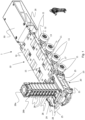
- Fig. 1 schematically shows a first embodiment of a part of a trailer system 1 according to the invention.
- the trailer system 1 of fig. 1 comprises a first trailer module 10.
- the first trailer module 10 is a trailer module of a self-propelled modular trailer (SPMT) system.
- SPMT self-propelled modular trailer
- the first trailer module 10 comprises a plurality of wheels 11.
- the wheels 11 - and optionally all of the wheels 11 - are rotatable around a horizontal axis 12 and also pivotable or rotatable around a vertical axis 13.
- the position of each wheel 11 around its vertical axis of rotation 13 can be controlled individually, so that the first trailer module 10 is able to move in all directions over the surface onto which it is located.
- the rotational speed of each wheel 11 around its horizontal axis of rotation 12 can be controlled individually.
- the wheels 11 are grouped in pairs, and the rotation around the horizontal axis 12 and/or around the vertical axis 13 is controlled per pair of wheels.
- the first trailer module 1 further comprises a loading bed 15. Objects to be transported are to be arranged on the loading bed 15, either directly or on loading bed supports which are arranged on the loading bed 15.
- the loading bed has an upper surface 16.
- the first trailer module 10 further comprises a primary loading bed connector 17 for rigidly connecting the loading bed 15 of the first trailer module 10 to a loading bed of a further trailer module to form a combined rigid loading bed.
- the primary loading bed connector 17 is arranged below the upper surface 16 of the loading bed 15 of the first trailer module 10.
- the trailer system according to fig. 1 further comprises a first jack system 20.
- the first jack system 20 comprises a first jack cradle 21.
- the first jack cradle 21 comprises a jack holder 22 (see fig. 2 ) and a jack 23.
- the jack 23 is accommodated in the jack holder 22.
- the first jack cradle 21 further comprises a primary cradle connector 25, which is connected to the primary loading bed connector 17 of the first trailer module. Therewith the primary cradle connector 25 connects the first jack cradle 21 to the first trailer module 10.
- the jack holder 22 extends at least partly below the upper surface 16 of the loading bed 15 of the of the first trailer module 10.
- the jack holder 22 also at least partly extends below the primary cradle connector 25.
- the jack 23 is located below the upper surface 16 of the loading bed 15, and also below the primary loading bed connector 17 and below the primary cradle connector 25.
- the first jack cradle 21 further comprises a secondary cradle connector 26, to allow to attach further trailer modules and/or jack systems to the trailer system of fig. 1 .
- the loading bed 15 of the first trailer module 10 has a long side and a first short side, and the first jack system 20 is connected to the first short side of the loading bed 15 of the first trailer module 10.
- the first jack system 20 does not extend beyond the width of the loading bed 15 of the first trailer module 10, so the width of the first jack system 20 extends entirely between a first longitudinal end and a second longitudinal end (which is opposite to the first longitudinal end) of the first short side of the loading bed 15 of the first trailer module 10.
- the first jack system 20 may extend above and/or below the first short side of the loading bed 15 of the first trailer module 10.
- the first jack cradle 21 does not extend beyond the width of the loading bed 15 of the first trailer module 10. So, the width of the first jack cradle 21 extends entirely between a first longitudinal end and a second longitudinal end (which is opposite to the first longitudinal end) of the first short side of the loading bed 15 of the first trailer module 10. The first jack cradle 21 may extend above and/or below the first short side of the loading bed 15 of the first trailer module 10.
- the jack system 20 further comprises a plurality of jack cassettes 28.
- the jack cassettes 28 are used to lift (or lower) an object over a larger length than the length of the stroke of the jack 23.
- the jack 23 is adapted to lift a first jack cassette 28a over the length of its stroke into a first position into a first elevated position. So, the jack 23 is moved into an extended position while it engages the first jack cassette 28. Then, the first jack cassette is supported in the first elevated position, and the jack 23 retracts to its retracted position.
- a second jack cassette 28b is arranged on top of the jack surface, and the first jack cassette28a continues to be supported in the first elevated position.
- the jack 23 then lifts the second jack cassette 28b into the first elevated position, and the first jack cassette 28a moves upwards along with the second jack cassette 28b. This process is repeated until the first jack cassette 28a reaches its required height. To lower the first jack cassette 28a again, the steps are carried out in the reverse order.
- the jack 23 has an upper jack surface which is moveable between a retracted position and an extended position
- the jack holder 22 has an opening 29 which allows to insert a jack cassette 28, 28a, 28b on the upper jack surface when the upper jack surface is in its retracted position.
- the opening 29 is for example arranged in a side or in a bottom of the jack holder 22.
- the first trailer module 10 further comprises a power unit 30 which is adapted to control the rotation of the wheels 11 of the first trailer module.
- the power unit 30 is arranged on the first trailer module 10 on a side opposite to where the first jack cradle 21 is connected to the first trailer module 10.
- the trailer module 10 comprises a secondary loading bed connector 18 for rigidly connecting the loading bed of the first trailer module 10 to a loading bed of a second further trailer module to form a combined rigid loading bed.
- the secondary loading bed connector 18 is arranged below the upper surface 16 of the loading bed 15 of the first trailer module 10.
- the secondary loading bed connector 18 is arranged at an opposite side of the loading bed 15 with respect to the primary loading bed connector 17.
- the power unit 30 is in this embodiment connected to the trailer module 10 by the secondary loading bed connector 18.
- the power unit 30 is configured to control the rotation of the wheels 11 of the first trailer module 10.
- the power unit 30 is configured to control the rotation of the wheels 11 of the first trailer module 10 around a horizontal axis of rotation 12 as well as around a vertical axis of rotation 13.
- the power unit 30 is configured to separately control the rotation of each of the plurality of wheels 11 of the first trailer module 10 separately.
- the power unit 30 is configured to separately control the rotation of each one of the plurality of wheels 11 of the first trailer module 10 around a horizontal axis of rotation 12 and about a vertical axis of rotation 13.
- the power unit 30 is configured to control the rotational speed of each wheel 11 around its horizontal axis of rotation 12.
- the power unit 30 comprises a hydraulic system for controlling the rotation of at least one wheel 11, optionally for controlling the rotation of all wheels 11 of the first trailer module 30.
- the power unit 30 is also adapted to control the jack 23 of the jack system 20.
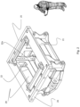
- Fig. 2 schematically shows an embodiment of a jack cradle 21 as can be used in the invention.
- the jack cradle 21 comprises a jack holder 22 which is adapted to accommodate a jack 23 (see fig. 1 ).
- the jack holder 22 comprises a space into which a jack can be arranged.
- mounting elements 22a are arranged to which the jack can be fixed inside the jack holder 22.
- the jack holder 22 has an opening 29 which allows to insert a jack cassette on an upper jack surface of a jack which is arranged in the jack holder, when the upper jack surface is in its retracted position.
- the opening 29 is in the embodiment arranged in a side of the jack holder 22.
- the jack cradle 21 further comprises a primary cradle connector 25, which is connectable to the primary loading bed connector 17 of the first trailer module. Therewith the primary cradle connector 25 is adapted to connect the first jack cradle 21 to the first trailer module 10.
- the jack holder 22 extends below the primary cradle connector 25.
- the first jack cradle 21 further comprises a secondary cradle connector 26, to allow to attach further trailer modules and/or jack systems.
- the jack cradle 21 as is shown in fig. 2 can be applied in any of the jack systems as described above or below.
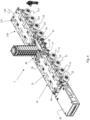
- Fig. 3 schematically shows an embodiment of a trailer jack system according to the invention, which can also be used as a jack system in a trailer system according to the invention and in the method for transporting an object in accordance with the invention.
- the trailer jack system of fig. 3 can be used as jack system 20 in a trailer system according to the invention and in the method for transporting an object in accordance with the invention, comprises a jack cradle 21.
- the jack cradle 21 comprises a jack holder 22 which is adapted to accommodate a jack 23 (see fig. 1 ).
- the jack holder 22 comprises a space into which a jack can be arranged.
- the trailer jack system further comprises a plurality of jack cassettes 28, 28a, 28b.
- the jack cassettes 28 are used to lift (or lower) an object over a larger length than the length of the stroke of the jack 23.
- the jack 23 is adapted to lift a first jack cassette 28a over the length of its stroke into a first position into a first elevated position. So, the jack 23 is moved into an extended position while it engages the first jack cassette 28. Then, the first jack cassette is supported in the first elevated position, and the jack 23 retracts to its retracted position.
- a second jack cassette 28b is arranged on top of the jack surface, and the first jack cassette 28a continues to be supported in the first elevated position.
- the jack 23 then lifts the second jack cassette 28b into the first elevated position, and the first jack cassette 28a moves upwards along with the second jack cassette 28b. This process is repeated until the first jack cassette 28a reaches its required height. To lower the first jack cassette 28a again, the steps are carried out in the reverse order.
- the jack holder 22 has an opening 29 which allows to insert a jack cassette 28a, 28b, 28 on an upper jack surface of a jack which is arranged in the jack holder, when the upper jack surface is in its retracted position.
- the opening 29 is in the embodiment arranged in a side of the jack holder 22.
- the trailer jack system further comprises a feeder mechanism 35, which is adapted to insert a jack cassette 28 into the opening 29 and to arrange it above the upper jack surface.
- the trailer jack system further comprises a support mechanism 36 which is adapted to support a jack cassette 28a or a stack of jack cassettes 28, 28a, 28b.
- a support mechanism 36 which is adapted to support a jack cassette 28a or a stack of jack cassettes 28, 28a, 28b.
- the support mechanism 36 releases the jack cassette 28a or stack of jack cassettes 28, 28a, 28b to allow the desired movement up or down.
- the support mechanism 36 engages the jack cassette 28a or stack of jack cassettes 28, 28a, 28b again.
- the jack cradle 21 further comprises a primary cradle connector 25, which is connectable to the primary loading bed connector 17 of the first trailer module. Therewith the primary cradle connector 25 is adapted to connect the first jack cradle 21 to the first trailer module 10.
- the jack holder 22 extends below the primary cradle connector 25.
- the first jack cradle 21 further comprises a secondary cradle connector 26, to allow to attach further trailer modules and/or jack systems.
- Fig. 4 schematically shows a second embodiment of a trailer system 1 according to the invention.
- the trailer system contains the following array: first trailer module 10 - first jack system 20 - second trailer module 110.
- the trailer system 1 of fig. 4 comprises a first trailer module 10.
- the first trailer module 10 is a trailer module of a self-propelled modular trailer (SPMT) system.
- SPMT self-propelled modular trailer
- the first trailer module 10 comprises a plurality of wheels 11.
- the wheels 11 - and optionally all of the wheels 11 - are rotatable around a horizontal axis 12 and also pivotable or rotatable around a vertical axis 13.
- the position of each wheel 11 around its vertical axis of rotation 13 can be controlled individually, so that the first trailer module 10 is able to move in all directions over the surface onto which it is located.
- the rotational speed of each wheel 11 around its horizontal axis of rotation 12 can be controlled individually.
- the wheels 11 are grouped in pairs, and the rotation around the horizontal axis 12 and/or around the vertical axis 13 is controlled per pair of wheels.
- the first trailer module 1 further comprises a loading bed 15. Objects to be transported are to be arranged on the loading bed 15, either directly or on loading bed supports which are arranged on the loading bed 15.
- the loading bed has an upper surface 16.
- the first trailer module 10 further comprises a primary loading bed connector 17 for rigidly connecting the loading bed 15 of the first trailer module 10 to a loading bed of a further trailer module to form a combined rigid loading bed.
- the primary loading bed connector 17 is arranged below the upper surface 16 of the loading bed 15 of the first trailer module 10.
- the trailer system according to fig. 4 further comprises a first jack system 20.
- the first jack system 20 comprises a first jack cradle 21.
- the first jack system 20 is for example a jack system in accordance with fig. 3 .
- the first jack cradle 21 comprises a jack holder 22 (see fig. 2 ) and a jack 23.
- the jack 23 is accommodated in the jack holder 22.
- the first jack cradle 21 further comprises a primary cradle connector 25, which is connected to the primary loading bed connector 17 of the first trailer module. Therewith the primary cradle connector 25 connects the first jack cradle 21 to the first trailer module 10.
- the jack holder 22 extends at least partly below the upper surface 16 of the loading bed 15 of the of the first trailer module 10.
- the jack holder 22 also at least partly extends below the primary cradle connector 25.
- the jack 23 is located below the upper surface 16 of the loading bed 15, and also below the primary loading bed connector 17 and below the primary cradle connector 25.
- the loading bed 15 of the first trailer module 10 has a long side and a first short side, and the first jack system 20 is connected to the first short side of the loading bed 15 of the first trailer module 10.
- the first jack system 20 does not extend beyond the width of the loading bed 15 of the first trailer module 10, so the width of the first jack system 20 extends entirely between a first longitudinal end and a second longitudinal end (which is opposite to the first longitudinal end) of the first short side of the loading bed 15 of the first trailer module 10.
- the first jack system 20 may extend above and/or below the first short side of the loading bed 15 of the first trailer module 10.
- the first jack cradle 21 does not extend beyond the width of the loading bed 15 of the first trailer module 10. So, the width of the first jack cradle 21 extends entirely between a first longitudinal end and a second longitudinal end (which is opposite to the first longitudinal end) of the first short side of the loading bed 15 of the first trailer module 10. The first jack cradle 21 may extend above and/or below the first short side of the loading bed 15 of the first trailer module 10.
- the first trailer module 10 further comprises a power unit 30 which is adapted to control the rotation of the wheels 11 of the first trailer module.
- the power unit 30 is arranged on the first trailer module 10 on a side opposite to where the first jack cradle 21 is connected to the first trailer module 10.
- the trailer module 10 comprises a secondary loading bed connector 18 for rigidly connecting the loading bed of the first trailer module 10 to a loading bed of a second further trailer module to form a combined rigid loading bed.
- the secondary loading bed connector 18 is arranged below the upper surface 16 of the loading bed 15 of the first trailer module 10.
- the secondary loading bed connector 18 is arranged at an opposite side of the loading bed 15 with respect to the primary loading bed connector 17.
- the power unit 30 is in this embodiment connected to the trailer module 10 by the secondary loading bed connector 18.
- the power unit 30 is configured to control the rotation of the wheels 11 of the first trailer module 10.
- the power unit 30 is configured to control the rotation of the wheels 11 of the first trailer module 10 around a horizontal axis of rotation 12 as well as around a vertical axis of rotation 13.
- the power unit 30 is configured to separately control the rotation of each of the plurality of wheels 11 of the first trailer module 10 separately.
- the power unit 30 is configured to separately control the rotation of each one of the plurality of wheels 11 of the first trailer module 10 around a horizontal axis of rotation 12 and about a vertical axis of rotation 13.
- the power unit 30 is configured to control the rotational speed of each wheel 11 around its horizontal axis of rotation 12.
- the power unit 30 comprises a hydraulic system for controlling the rotation of at least one wheel 11, optionally for controlling the rotation of all wheels 11 of the first trailer module 30.
- the trailer system further comprises a second trailer module 110.
- the second trailer module 110 is a trailer module of a self-propelled modular trailer (SPMT) system.
- SPMT self-propelled modular trailer
- the second trailer module 110 comprises a plurality of wheels 111.
- the wheels 111 - and optionally all of the wheels 111 - are rotatable around a horizontal axis 112 and also pivotable or rotatable around a vertical axis 113.
- the position of each wheel 111 around its vertical axis of rotation 113 can be controlled individually, so that the second trailer module 110 is able to move in all directions over the surface onto which it is located.
- the rotational speed of each wheel 111 around its horizontal axis of rotation 112 can be controlled individually.
- the wheels 111 are grouped in pairs, and the rotation around the horizontal axis 112 and/or around the vertical axis 113 is controlled per pair of wheels.
- the second trailer module 1 further comprises a loading bed 115. Objects to be transported are to be arranged on the loading bed 115, either directly or on loading bed supports which are arranged on the loading bed 115.
- the loading bed has an upper surface 116.
- the second trailer module 110 further comprises a primary loading bed connector 117 for rigidly connecting the loading bed 115 of the second trailer module 110 to a loading bed of a further trailer module to form a combined rigid loading bed.
- the primary loading bed connector 117 is arranged below the upper surface 116 of the loading bed 115 of the second trailer module 110.
- the first jack cradle 21 comprises a secondary cradle connector 26, which is connected to the primary loading bed connector 117 of the second trailer module 110 and therewith connects the first jack cradle 21 to the second trailer module 110.
- first jack cradle 21 is arranged between the first trailer module 10 and the second trailer module 110.
- trailer modules and/or further jack systems and/or power units may be present in this embodiment of the trailer system.
- Fig. 5 schematically shows a third embodiment of a trailer system 1 according to the invention.
- the trailer system contains two arrays.
- the first array comprises: first trailer module 10 - first jack system 20 - second trailer module 110.
- the second array comprises: third trailer module 210 - second jack system 120 - fourth trailer module 310.
- the first jack system 20 and the second jack system 120 are for example jack systems in accordance with fig. 3 .
- the first and the second array are connected to each other by a first connector beam 40.
- the first connector beam 40 has a first end 41 which is connected to the jack cradle of the first jack system 20 and a second end 42 which is connected to the jack cradle of the second jack 120.
- the first connector beam 40 is a lattice beam.
- the first trailer module 10 is for example of the same type as the first trailer module 10 in the embodiment of fig. 4 .
- the second trailer module 110 is for example of the same type as the second trailer module 110 in the embodiment of fig. 4 .
- the third trailer module 210 is for example of the same type as the first trailer module 10 in the embodiment of fig. 4 .
- the fourth trailer module 310 is for example of the same type as the second trailer module 110 in the embodiment of fig. 4 .
- the first array is provided with power unit 30, and the second array is provided with power unit 130.
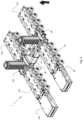
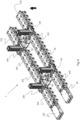
- Fig. 6 schematically shows a fourth embodiment of a trailer system 1 according to the invention.
- the trailer system contains two arrays.
- the first array comprises: fifth trailer module 410 - first jack system 20 - first trailer module 10 - second trailer module 110 - second jack system 120 - sixth trailer module 510.
- the second array comprises: seventh trailer module 610 - third jack system 220 - third trailer module 210 - fourth trailer module 310 - fourth jack system 320 - eighth trailer module 710.
- the first jack system 20, the second jack system 120, third jack system 220 and fourth jack system 320 are for example jack systems in accordance with fig. 3 .
- the first and the second array are connected to each other by a first connector beam 40 and by a second connector beam 50.
- the first connector beam 40 has a first end which is connected to the jack cradle of the first jack system 20 and a second end which is connected to the jack cradle of the third jack 220.
- the first connector beam 40 is a lattice beam.
- the second connector beam 50 has a first end which is connected to the jack cradle of the second jack system 120 and a second end which is connected to the jack cradle of the fourth jack 320.
- the second connector beam 50 is a lattice beam.
- the trailer modules 10 are for example of the same type as the first trailer module 10 and/or the second trailer module 120 in the embodiment of fig. 4 .
- the first array is provided with power unit 30, and the second array is provided with power unit 130.
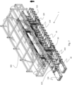
- Fig. 7 shows a trailer system 1 in accordance with the embodiment of fig. 6 , in use for transporting a pipe rack 800.
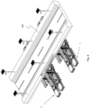
- Fig. 8 shows a first trailer system 1 in accordance with the embodiment of fig. 6 and a second trailer system 1 also in accordance with the embodiment of fig. 6 , in use for together transporting a bridge deck 900.
Landscapes
- Engineering & Computer Science (AREA)
- Mechanical Engineering (AREA)
- Transportation (AREA)
- Combustion & Propulsion (AREA)
- Chemical & Material Sciences (AREA)
- Public Health (AREA)
- Health & Medical Sciences (AREA)
- Life Sciences & Earth Sciences (AREA)
- Geology (AREA)
- Structural Engineering (AREA)
- Handcart (AREA)
- Vehicle Cleaning, Maintenance, Repair, Refitting, And Outriggers (AREA)
- Vehicle Body Suspensions (AREA)
- Types And Forms Of Lifts (AREA)
Claims (13)
- Anhängersystem (1), Folgendes umfassend:- ein erstes Anhängermodul (10), wobei das erste Anhängermodul (10) Folgendes umfasst:- mehrere Räder (11),- eine Ladefläche (15),- einen primären Ladeflächenverbinder (17) zum steifen Verbinden der Ladefläche (15) des ersten Anhängermoduls (10) mit der Ladefläche eines weiteren Anhängermoduls, um eine kombinierte steife Ladefläche auszubilden, wobei der primäre Ladeflächenverbinder (17) unter einer oberen Fläche (16) der Ladefläche (15) des ersten Anhängermoduls (10) angeordnet ist,- ein erstes Hebersystem (20), umfassend einen ersten Heberkorb (21), wobei der erste Heberkorb (21) Folgendes umfasst:- eine Heberhalterung (22) und einen Heber (23), der in der Heberhalterung (22) aufgenommen ist,- einen primären Korbverbinder (25), der mit dem primären Ladeflächenverbinder (17) des ersten Anhängermoduls (10) verbunden ist und dadurch den ersten Heberkorb (21) mit dem ersten Anhängermodul (10) verbindet,wobei sich die Heberhalterung (22) des ersten Heberkorbs (21) zumindest teilweise unter die obere Fläche (16) der Ladefläche des ersten Anhängermoduls (10) erstreckt,wobei das Anhängersystem (1) ferner ein zweites Anhängermodul (110) umfasst, wobei das zweite Anhängermodul (110) Folgendes umfasst:- mehrere Räder (111),- eine Ladefläche (115),- einen primären Ladeflächenverbinder (117) zum steifen Verbinden der Ladefläche (115) des zweiten Anhängermoduls (110) mit der Ladefläche eines weiteren Anhängermoduls, um eine kombinierte steife Ladefläche auszubilden, wobei der primäre Ladeflächenverbinder unter einer oberen Fläche (116) der Ladefläche (115) des zweiten Anhängermoduls (110) angeordnet ist,und wobei der erste Heberkorb (21) einen sekundären Korbverbinder (26) umfasst, der mit dem primären Ladeflächenverbinder (117) des zweiten Anhängermoduls (110) verbunden ist und dadurch den ersten Heberkorb (21) mit dem zweiten Anhängermodul (110) verbindet,und wobei der erste Heberkorb (21) zwischen dem ersten Anhängermodul (10) und dem zweiten Anhängermodul (110) angeordnet ist.
- Anhängersystem nach Anspruch 1,
wobei sich die Heberhalterung (22) zumindest teilweise unter den primären Korbverbinder (25) erstreckt. - Anhängersystem nach einem der vorstehenden Ansprüche,
wobei der Heber (23) eine obere Heberfläche aufweist, wobei die obere Heberfläche in eine Position unter der Höhe der oberen Fläche (16) der Ladefläche (15) des ersten Anhängermoduls (10) oder auf dieselbe Höhe wie die obere Fläche (10) der Ladefläche (16) des ersten Anhängermoduls (10) einziehbar ist. - Anhängersystem nach einem der vorstehenden Ansprüche,wobei das Hebersystem ferner eine Heberkassette (28, 28a, 28b) umfasst undwobei der Heber eine obere Heberfläche aufweist, die zwischen einer eingezogenen Position und einer ausgezogenen Position beweglich ist, und wobei die Heberhalterung eine Öffnung (29) aufweist, die das Einsetzen der Heberkassette auf der oberen Heberfläche zulässt, wenn sich die obere Heberfläche in der eingezogenen Position befindet.
- Anhängersystem nach Anspruch 4,
wobei sich die eingezogene Position der oberen Heberfläche unter der Höhe der oberen Fläche (16) der Ladefläche (15) des ersten Anhängermoduls (10) befindet. - Anhängersystem nach einem der vorstehenden Ansprüche,
wobei das erste Anhängermodul (10) ferner eine Antriebseinheit (30) umfasst, die dazu eingerichtet ist, die Drehung der Räder (11) des ersten Anhängermoduls (10) zu steuern, wobei die Antriebseinheit (30) am ersten Anhängermodul auf einer Seite angeordnet ist, die der Seite, auf welcher der erste Heberkorb (21) mit dem ersten Anhängermodul (10) verbunden ist, entgegengesetzt ist. - Anhängersystem nach einem der vorstehenden Ansprüche,wobei das Anhängersystem ferner ein drittes Anhängermodul (210) umfasst, wobei das dritte Anhängermodul (210) Folgendes umfasst:- mehrere Räder,- eine Ladefläche,- einen primären Ladeflächenverbinder zum steifen Verbinden der Ladefläche des dritten Anhängermoduls mit der Ladefläche eines weiteren Anhängermoduls, um eine kombinierte steife Ladefläche auszubilden, wobei der primäre Ladeflächenverbinder unter einer oberen Fläche der Ladefläche des dritten Anhängermoduls angeordnet ist, und wobei das Anhängersystem ferner ein zweites Hebersystem (120) umfasst, das einen zweiten Heberkorb umfasst, wobei der zweite Heberkorb Folgendes umfasst:- eine Heberhalterung und einen Heber, der in der Heberhalterung aufgenommen ist,- einen primären Korbverbinder, der mit dem primären Ladeflächenverbinder des dritten Anhängermoduls verbunden ist und dadurch den zweiten Heberkorb mit dem dritten Anhängermodul verbindet,wobei sich die Heberhalterung des zweiten Heberkorbs zumindest teilweise unter die obere Fläche der Ladefläche des dritten Anhängermoduls erstreckt,und wobei das Anhängersystem ferner einen ersten Verbindungsbalken (40) umfasst, der mit dem ersten Ende (41) mit dem ersten Heberkorb verbunden ist und mit dem zweiten Ende (42) mit dem zweiten Heberkorb verbunden ist.
- Anhängersystem (1), Folgendes umfassend:- ein erstes Anhängermodul (10), wobei das erste Anhängermodul (10) Folgendes umfasst:- mehrere Räder (11),- eine Ladefläche (15),- einen primären Ladeflächenverbinder (17) zum steifen Verbinden der Ladefläche (15) des ersten Anhängermoduls (10) mit der Ladefläche eines weiteren Anhängermoduls, um eine kombinierte steife Ladefläche auszubilden, wobei der primäre Ladeflächenverbinder (17) unter einer oberen Fläche (16) der Ladefläche (15) des ersten Anhängermoduls (10) angeordnet ist,- einen sekundären Ladeflächenverbinder (18) zum steifen Verbinden der Ladefläche (15) des ersten Anhängermoduls (10) mit der Ladefläche eines zweiten weiteren Anhängermoduls, um eine kombinierte steife Ladefläche auszubilden, wobei der sekundäre Ladeflächenverbinder unter einer oberen Fläche der Ladefläche (15) des ersten Anhängermoduls (10) angeordnet ist, wobei der sekundäre Ladeflächenverbinder (18) in Bezug zum primären Ladeflächenverbinder auf einer entgegengesetzten Seite der Ladefläche angeordnet ist,- ein erstes Hebersystem (20), umfassend einen ersten Heberkorb (21), wobei der erste Heberkorb (21) Folgendes umfasst:- eine Heberhalterung (22) und einen Heber (23), der in der Heberhalterung (22) aufgenommen ist,- einen primären Korbverbinder (25), der mit dem primären Ladeflächenverbinder (17) des ersten Anhängermoduls (10) verbunden ist und dadurch den ersten Heberkorb (21) mit dem ersten Anhängermodul (10) verbindet,wobei sich die Heberhalterung (22) des ersten Heberkorbs (21) zumindest teilweise unter die obere Fläche (16) der Ladefläche (15) des ersten Anhängermoduls (10) erstreckt,- ein zweites Hebersystem (120), umfassend einen zweiten Heberkorb, wobei der zweite Heberkorb Folgendes umfasst:- eine Heberhalterung und einen Heber, der in der Heberhalterung aufgenommen ist,- einen primären Korbverbinder, der mit dem sekundären Ladeflächenverbinder des ersten Anhängermoduls verbunden ist und dadurch den zweiten Heberkorb mit dem ersten Anhängermodul verbindet,wobei sich die Heberhalterung des zweiten Heberkorbs zumindest teilweise unter die obere Fläche der Ladefläche des ersten Anhängermoduls erstreckt,- ein zweites Anhängermodul (110), wobei das zweite Anhängermodul (110) Folgendes umfasst:- mehrere Räder (111),- eine Ladefläche (115),- einen primären Ladeflächenverbinder (117) zum steifen Verbinden der Ladefläche (115) des zweiten Anhängermoduls (110) mit der Ladefläche eines weiteren Anhängermoduls, um eine kombinierte steife Ladefläche auszubilden, wobei der primäre Ladeflächenverbinder (117) unter einer oberen Fläche (116) der Ladefläche (115) des zweiten Anhängermoduls (110) angeordnet ist,- einen sekundären Ladeflächenverbinder zum steifen Verbinden der Ladefläche des zweiten Anhängermoduls mit der Ladefläche eines zweiten weiteren Anhängermoduls, um eine kombinierte steife Ladefläche auszubilden, wobei der sekundäre Ladeflächenverbinder unter einer oberen Fläche (116) der Ladefläche (115) des zweiten Anhängermoduls (110) angeordnet ist, wobei der sekundäre Ladeflächenverbinder in Bezug zum primären Ladeflächenverbinder auf einer entgegengesetzten Seite der Ladefläche angeordnet ist,- ein drittes Hebersystem (220), umfassend einen dritten Heberkorb, wobei der dritte Heberkorb Folgendes umfasst:- eine Heberhalterung und einen Heber, der in der Heberhalterung aufgenommen ist,- einen primären Korbverbinder, der mit dem primären Ladeflächenverbinder des zweiten Anhängermoduls verbunden ist und dadurch den dritten Heberkorb mit dem zweiten Anhängermodul verbindet,wobei sich die Heberhalterung des dritten Heberkorbs zumindest teilweise unter die obere Fläche der Ladefläche des zweiten Anhängermoduls erstreckt,- ein viertes Hebersystem (320), umfassend einen vierten Heberkorb, wobei der vierte Heberkorb Folgendes umfasst:- eine Heberhalterung und einen Heber, der in der Heberhalterung aufgenommen ist,- einen primären Korbverbinder, der mit dem sekundären Ladeflächenverbinder des zweiten Anhängermoduls verbunden ist und dadurch den vierten Heberkorb mit dem zweiten Anhängermodul verbindet,wobei sich die Heberhalterung des vierten Heberkorbs zumindest teilweise unter die obere Fläche der Ladefläche des zweiten Anhängermoduls erstreckt,- einen ersten Verbindungsbalken (40), der mit dem ersten Ende mit dem ersten Heberkorb verbunden ist und mit dem zweiten Ende mit dem dritten Heberkorb verbunden ist,- einen zweiten Verbindungsbalken (50), der mit dem ersten Ende mit dem zweiten Heberkorb verbunden ist und mit dem zweiten Ende mit dem vierten Heberkorb verbunden ist,wobei das Anhängersystem ferner eine erste Anordnung, umfassend das erste Hebersystem, das erste Anhängermodul und das zweite Hebersystem, und eine zweite Anordnung, umfassend das dritte Hebersystem, das zweite Anhängermodul und das weitere Hebersystem, umfasst, wobei weitere Anhängermodule in mindestens einer der Anordnungen vorhanden sind.
- Anhängersystem (1), Folgendes umfassend:- ein erstes Anhängermodul (10), wobei das erste Anhängermodul (10) Folgendes umfasst:- mehrere Räder (11),- eine Ladefläche (15),- einen primären Ladeflächenverbinder (17) zum steifen Verbinden der Ladefläche (15) des ersten Anhängermoduls (10) mit der Ladefläche eines weiteren Anhängermoduls, um eine kombinierte steife Ladefläche auszubilden, wobei der primäre Ladeflächenverbinder (17) unter einer oberen Fläche (16) der Ladefläche (15) des ersten Anhängermoduls (10) angeordnet ist, - einen sekundären Ladeflächenverbinder (18) zum steifen Verbinden der Ladefläche (15) des ersten Anhängermoduls (10) mit der Ladefläche eines zweiten weiteren Anhängermoduls, um eine kombinierte steife Ladefläche auszubilden, wobei der sekundäre Ladeflächenverbinder (18) unter einer oberen Fläche (16) der Ladefläche (15) des ersten Anhängermoduls (10) angeordnet ist, wobei der sekundäre Ladeflächenverbinder (18) in Bezug zum primären Ladeflächenverbinder auf einer entgegengesetzten Seite der Ladefläche angeordnet ist,- ein erstes Hebersystem (20), umfassend einen ersten Heberkorb (21), wobei der erste Heberkorb (21) Folgendes umfasst:- eine Heberhalterung (22) und einen Heber (23), der in der Heberhalterung (22) aufgenommen ist,- einen primären Korbverbinder (25), der mit dem primären Ladeflächenverbinder (17) des ersten Anhängermoduls (10) verbunden ist und dadurch den ersten Heberkorb (21) mit dem ersten Anhängermodul (10) verbindet,wobei sich die Heberhalterung (22) des ersten Heberkorbs (21) zumindest teilweise unter die obere Fläche (16) der Ladefläche (15) des ersten Anhängermoduls (10) erstreckt,- ein zweites Anhängermodul (110), wobei das zweite Anhängermodul (110) Folgendes umfasst:- mehrere Räder (111),- eine Ladefläche (115),- einen primären Ladeflächenverbinder (117) zum steifen Verbinden der Ladefläche (115) des zweiten Anhängermoduls (110) mit der Ladefläche eines weiteren Anhängermoduls, um eine kombinierte steife Ladefläche auszubilden, wobei der primäre Ladeflächenverbinder (117) unter einer oberen Fläche (116) der Ladefläche (115) des zweiten Anhängermoduls (110) angeordnet ist,- einen sekundären Ladeflächenverbinder zum steifen Verbinden der Ladefläche des zweiten Anhängermoduls mit der Ladefläche eines zweiten weiteren Anhängermoduls, um eine kombinierte steife Ladefläche auszubilden, wobei der sekundäre Ladeflächenverbinder unter einer oberen Fläche (116) der Ladefläche (115) des zweiten Anhängermoduls (110) angeordnet ist, wobei der sekundäre Ladeflächenverbinder in Bezug zum primären Ladeflächenverbinder auf einer entgegengesetzten Seite der Ladefläche angeordnet ist,- ein zweites Hebersystem (120), umfassend einen zweiten Heberkorb, wobei der zweite Heberkorb Folgendes umfasst:- eine Heberhalterung und einen Heber, der in der Heberhalterung aufgenommen ist,- einen primären Korbverbinder, der mit dem primären Ladeflächenverbinder des zweiten Anhängermoduls verbunden ist und dadurch den zweiten Heberkorb mit dem zweiten Anhängermodul verbindet,wobei sich die Heberhalterung des zweiten Heberkorbs zumindest teilweise unter die obere Fläche der Ladefläche des zweiten Anhängermoduls erstreckt,
wobei der sekundäre Ladeflächenverbinder des ersten Anhängermoduls mit dem sekundären Ladeflächenverbinder des zweiten Anhängermoduls verbunden ist,- ein drittes Anhängermodul (210), wobei das dritte Anhängermodul Folgendes umfasst:- mehrere Räder,- eine Ladefläche,- einen primären Ladeflächenverbinder zum steifen Verbinden der Ladefläche des dritten Anhängermoduls mit der Ladefläche eines weiteren Anhängermoduls, um eine kombinierte steife Ladefläche auszubilden, wobei der primäre Ladeflächenverbinder unter einer oberen Fläche der Ladefläche des dritten Anhängermoduls angeordnet ist,- einen sekundären Ladeflächenverbinder zum steifen Verbinden der Ladefläche des dritten Anhängermoduls mit der Ladefläche eines zweiten weiteren Anhängermoduls, um eine kombinierte steife Ladefläche auszubilden, wobei der sekundäre Ladeflächenverbinder unter einer oberen Fläche der Ladefläche des dritten Anhängermoduls angeordnet ist, wobei der sekundäre Ladeflächenverbinder in Bezug zum primären Ladeflächenverbinder auf einer entgegengesetzten Seite der Ladefläche angeordnet ist,- ein drittes Hebersystem (220), umfassend einen dritten Heberkorb, wobei der dritte Heberkorb Folgendes umfasst:- eine Heberhalterung und einen Heber, der in der Heberhalterung aufgenommen ist,- einen primären Korbverbinder, der mit dem primären Ladeflächenverbinder des dritten Anhängermoduls verbunden ist und dadurch den dritten Heberkorb mit dem dritten Anhängermodul verbindet,wobei sich die Heberhalterung des dritten Heberkorbs zumindest teilweise unter die obere Fläche der Ladefläche des dritten Anhängermoduls erstreckt,- ein viertes Anhängermodul (310), wobei das vierte Anhängermodul Folgendes umfasst:- mehrere Räder,- eine Ladefläche,- einen primären Ladeflächenverbinder zum steifen Verbinden der Ladefläche des vierten Anhängermoduls mit der Ladefläche eines weiteren Anhängermoduls, um eine kombinierte steife Ladefläche auszubilden, wobei der primäre Ladeflächenverbinder unter einer oberen Fläche der Ladefläche des vierten Anhängermoduls angeordnet ist,- einen sekundären Ladeflächenverbinder zum steifen Verbinden der Ladefläche des vierten Anhängermoduls mit der Ladefläche eines zweiten weiteren Anhängermoduls, um eine kombinierte steife Ladefläche auszubilden, wobei der sekundäre Ladeflächenverbinder unter einer oberen Fläche der Ladefläche des vierten Anhängermoduls angeordnet ist, wobei der sekundäre Ladeflächenverbinder in Bezug zum primären Ladeflächenverbinder auf einer entgegengesetzten Seite der Ladefläche angeordnet ist,- ein viertes Hebersystem (320), umfassend einen vierten Heberkorb, wobei der vierte Heberkorb Folgendes umfasst:- eine Heberhalterung und einen Heber, der in der Heberhalterung aufgenommen ist,- einen primären Korbverbinder, der mit dem sekundären Ladeflächenverbinder des vierten Anhängermoduls verbunden ist und dadurch den vierten Heberkorb mit dem vierten Anhängermodul verbindet,wobei sich die Heberhalterung des vierten Heberkorbs zumindest teilweise unter die obere Fläche der Ladefläche des vierten Anhängermoduls erstreckt,
wobei der sekundäre Ladeflächenverbinder des dritten Anhängermoduls mit dem sekundären Ladeflächenverbinder des vierten Anhängermoduls verbunden ist,- einen ersten Verbindungsbalken, der mit dem ersten Ende mit dem ersten Heberkorb verbunden ist und mit dem zweiten Ende mit dem dritten Heberkorb verbunden ist,- einen zweiten Verbindungsbalken, der mit dem ersten Ende mit dem zweiten Heberkorb verbunden ist und mit dem zweiten Ende mit dem vierten Heberkorb verbunden ist,wobei das Anhängersystem ferner eine erste Anordnung, umfassend das erste Hebersystem, das erste Anhängermodul, das zweite Anhängermodul und das zweite Hebersystem, und eine zweite Anordnung, umfassend das dritte Hebersystem, das dritte Anhängermodul, das vierte Anhängermodul und das vierte Hebersystem, umfasst,wobei weitere Anhängermodule in mindestens einer der Anordnungen vorhanden sind. - Verfahren zum Transportieren eines Objekts durch ein Anhängersystem (1), wobei das Verfahren die folgenden Schritte umfasst:- Verbinden eines ersten Hebersystems (20) mit einem ersten Anhängermodul (10), um ein Anhängersystem auszubilden, wobei das erste Anhängermodul (10) Folgendes umfasst:- mehrere Räder (11),- eine Ladefläche (15),- einen primären Ladeflächenverbinder (17) zum steifen Verbinden der Ladefläche (15) des ersten Anhängermoduls (10) mit der Ladefläche eines weiteren Anhängermoduls, um eine kombinierte steife Ladefläche auszubilden, wobei der primäre Ladeflächenverbinder (17) unter einer oberen Fläche (16) der Ladefläche (15) des ersten Anhängermoduls (10) angeordnet ist,und wobei das erste Hebersystem (20) einen ersten Heberkorb (21) umfasst, wobei der erste Heberkorb (21) Folgendes umfasst:- eine Heberhalterung (22) und einen Heber (23), der in der Heberhalterung (22) aufgenommen ist, wobei der Heber eine obere Heberfläche aufweist,- einen primären Korbverbinder (25),- wobei sich die primäre Heberhalterung (22) des ersten Heberkorbs zumindest teilweise unter die obere Fläche (16) der Ladefläche (15) des ersten Anhängermoduls (10) erstreckt,wobei der primäre Korbverbinder (25) mit dem primären Ladeflächenverbinder (17) des ersten Anhängermoduls verbunden ist, um die Verbindung des ersten Heberkorbs (21) mit dem ersten Anhängermodul (10) zu bewirken,wobei das Anhängersystem ferner ein zweites Anhängermodul (110) umfasst, wobei das zweite Anhängermodul (110) Folgendes umfasst:und wobei der erste Heberkorb (21) zwischen dem ersten Anhängermodul (10) und dem zweiten Anhängermodul (110) angeordnet ist,- mehrere Räder (111),- eine Ladefläche (115),- einen primären Ladeflächenverbinder (117) zum steifen Verbinden der Ladefläche (115) des zweiten Anhängermoduls (110) mit der Ladefläche eines weiteren Anhängermoduls, um eine kombinierte steife Ladefläche auszubilden, wobei der primäre Ladeflächenverbinder (117) unter einer oberen Fläche (116) der Ladefläche (115) des zweiten Anhängermoduls (110) angeordnet ist, und wobei der erste Heberkorb (21) einen zweiten Korbverbinder (26) umfasst, der mit dem primären Ladeflächenverbinder (117) des zweiten Anhängermoduls (110) verbunden ist und dadurch den ersten Heberkorb (21) mit dem zweiten Anhängermodul (110) verbindet,- Positionieren einer oberen Heberfläche (23) in einer Position unter der Höhe der oberen Fläche (16) der Ladefläche (15) des ersten Anhängermoduls (10) oder auf derselben Höhe wie die obere Fläche (16) der Ladefläche (15) des ersten Anhängermoduls (10),- Positionieren der Ladefläche (15) des ersten Anhängermoduls (10) unter dem zu transportierenden Objekt,- Aufwärtsbewegen der oberen Heberfläche, bis das Hebersystem (20) in das Objekt eingreift,- Drehen der Räder (11) des ersten Anhängermoduls (10), um das Anhängersystem (1) und das Objekt an einen Zielort zu bewegen.
- Verfahren nach Anspruch 10,
wobei das Verfahren nach dem Aufwärtsbewegen der oberen Heberfläche, bis das Hebersystem in das Objekt eingreift, ferner den Schritt des Anordnens des Objekts auf der Ladefläche (15) des ersten Anhängermoduls (10) umfasst, wobei der Schritt das Absenken der oberen Fläche des Hebers (23) beinhaltet. - Verfahren nach einem der Ansprüche 10-11,
wobei das Verfahren nach dem Bewegen des Anhängersystems und des Objekts zu einem Zielort den Schritt des Auf- und/oder Abwärtsbewegens des Objekts mittels des Hebesystems (20) umfasst. - Verfahren nach einem der Ansprüche 10-12,
wobei der Schritt des Aufwärtsbewegens der oberen Heberfläche, bis das Hebersystem (20) in das Objekt eingreift, Folgendes umfasst:- Anordnen einer ersten Heberkassette (28a) über der oberen Heberfläche,- Aufwärtsbewegen der oberen Heberfläche, wodurch die erste Heberkassette (28a) in eine erste angehobene Position gehoben wird,- Abstützen der ersten Heberkassette (28a) in der ersten angehobenen Position,- Abwärtsbewegen der oberen Heberfläche, während die erste Heberkassette (28a) in der ersten angehobenen Position gehalten wird,- Anordnen einer zweiten Heberkassette (28b) über der oberen Heberfläche und unter der ersten Heberkassette (28a),- Bewegen der zweiten Heberkassette (28b) in die erste angehobene Position, wodurch die erste Heberkassette (28a) in eine zweite angehobene Position gehoben wird, die sich über der ersten angehobenen Position befindet.
Priority Applications (1)
| Application Number | Priority Date | Filing Date | Title |
|---|---|---|---|
| EP24196770.2A EP4484218A1 (de) | 2020-06-29 | 2021-06-29 | Anhängersystem, verfahren zum transport eines objekts durch ein anhängersystem und anhängerhebersystem |
Applications Claiming Priority (2)
| Application Number | Priority Date | Filing Date | Title |
|---|---|---|---|
| NL2025942A NL2025942B1 (en) | 2020-06-29 | 2020-06-29 | Trailer system, method for transporting an object by a trailer system and trailer jack system |
| PCT/EP2021/067849 WO2022002936A1 (en) | 2020-06-29 | 2021-06-29 | Trailer system, method for transporting an object by a trailer system and trailer jack system |
Related Child Applications (1)
| Application Number | Title | Priority Date | Filing Date |
|---|---|---|---|
| EP24196770.2A Division EP4484218A1 (de) | 2020-06-29 | 2021-06-29 | Anhängersystem, verfahren zum transport eines objekts durch ein anhängersystem und anhängerhebersystem |
Publications (3)
| Publication Number | Publication Date |
|---|---|
| EP4171996A1 EP4171996A1 (de) | 2023-05-03 |
| EP4171996B1 true EP4171996B1 (de) | 2024-08-28 |
| EP4171996C0 EP4171996C0 (de) | 2024-08-28 |
Family
ID=74095957
Family Applications (2)
| Application Number | Title | Priority Date | Filing Date |
|---|---|---|---|
| EP24196770.2A Pending EP4484218A1 (de) | 2020-06-29 | 2021-06-29 | Anhängersystem, verfahren zum transport eines objekts durch ein anhängersystem und anhängerhebersystem |
| EP21736323.3A Active EP4171996B1 (de) | 2020-06-29 | 2021-06-29 | Anhängersystem, verfahren zum transport eines objekts durch ein anhängersystem und anhängerhebersystem |
Family Applications Before (1)
| Application Number | Title | Priority Date | Filing Date |
|---|---|---|---|
| EP24196770.2A Pending EP4484218A1 (de) | 2020-06-29 | 2021-06-29 | Anhängersystem, verfahren zum transport eines objekts durch ein anhängersystem und anhängerhebersystem |
Country Status (9)
| Country | Link |
|---|---|
| US (1) | US20230339384A1 (de) |
| EP (2) | EP4484218A1 (de) |
| JP (1) | JP2023543536A (de) |
| CN (1) | CN115843283A (de) |
| CA (1) | CA3184085A1 (de) |
| ES (1) | ES2991238T3 (de) |
| NL (1) | NL2025942B1 (de) |
| PL (1) | PL4171996T3 (de) |
| WO (1) | WO2022002936A1 (de) |
Families Citing this family (2)
| Publication number | Priority date | Publication date | Assignee | Title |
|---|---|---|---|---|
| NL2032977B1 (en) * | 2022-09-07 | 2024-03-21 | Mammoet Holding B V | Trailer stroke extender and hydraulic trailer system |
| BE1032758B1 (nl) * | 2024-07-09 | 2026-02-11 | Sarens | Inrichting en werkwijze voor het transporteren van een last voorbij obstakels in de lucht |
Citations (7)
| Publication number | Priority date | Publication date | Assignee | Title |
|---|---|---|---|---|
| DE202014004907U1 (de) | 2014-06-18 | 2015-09-22 | Scheuerle Fahrzeugfabrik Gmbh | Schwerlastfahrzeug mit Staplerfunktion |
| EP2974905A1 (de) | 2014-07-15 | 2016-01-20 | Mammoet Engineering B.V. | Verfahren und anordnung zum transport von schweren lasten |
| US20160257361A1 (en) | 2013-10-18 | 2016-09-08 | J.G.B.D. Consult Sprl | Heavy-load modular vehicle |
| US9834124B2 (en) | 2013-07-24 | 2017-12-05 | Agence Nationale Pour La Gestion Des Déchets Radioactifs | Wheeled vehicle for transferring heavy loads, having a plurality of low-height articulated modules |
| US20180339736A1 (en) | 2017-05-26 | 2018-11-29 | David W. Lutz | Modular Beam Hauler |
| NL1042448B1 (nl) | 2017-06-30 | 2019-01-14 | Ale R&D | vijzelinrichting |
| NL2019773B1 (en) | 2017-10-20 | 2019-04-29 | Mammoet Holding B V | Jack system for heavy loads, cup-shaped segment for a jack system, method of positioning a heavy load and method of transporting a jack system |
Family Cites Families (8)
| Publication number | Priority date | Publication date | Assignee | Title |
|---|---|---|---|---|
| JP3947280B2 (ja) * | 1997-10-17 | 2007-07-18 | 日本車輌製造株式会社 | 運搬車両 |
| US20070272489A1 (en) * | 2003-12-15 | 2007-11-29 | Putnam Brian P | Portable vehicle lift |
| DE102007032056B4 (de) * | 2007-07-02 | 2011-03-10 | Gessner, Thomas | Anhänger und Anhängerzug für Flurförderzeuge |
| CN201410912Y (zh) * | 2009-06-12 | 2010-02-24 | 上海西重所重型机械成套有限公司 | 升降横移组合式小车 |
| US9353537B2 (en) * | 2013-05-21 | 2016-05-31 | Monty Wensel | Apparatus, system and method for lifting a building |
| CN208698609U (zh) * | 2018-08-24 | 2019-04-05 | 昆山浩联锐科自动化设备有限公司 | 一种重型圆管运输自动导引车 |
| CN209096869U (zh) * | 2018-11-02 | 2019-07-12 | 宜昌大自然生物科技有限公司 | 一种用于袋料香菇生产中的高效运输设备 |
| AU2020248086B2 (en) * | 2019-03-28 | 2025-12-11 | Enerpac Heavy Lifting Technology B.V. | Self-locking jack |
-
2020
- 2020-06-29 NL NL2025942A patent/NL2025942B1/en active
-
2021
- 2021-06-29 WO PCT/EP2021/067849 patent/WO2022002936A1/en not_active Ceased
- 2021-06-29 ES ES21736323T patent/ES2991238T3/es active Active
- 2021-06-29 CN CN202180046650.8A patent/CN115843283A/zh active Pending
- 2021-06-29 PL PL21736323.3T patent/PL4171996T3/pl unknown
- 2021-06-29 US US18/008,561 patent/US20230339384A1/en active Pending
- 2021-06-29 CA CA3184085A patent/CA3184085A1/en active Pending
- 2021-06-29 JP JP2022580962A patent/JP2023543536A/ja active Pending
- 2021-06-29 EP EP24196770.2A patent/EP4484218A1/de active Pending
- 2021-06-29 EP EP21736323.3A patent/EP4171996B1/de active Active
Patent Citations (7)
| Publication number | Priority date | Publication date | Assignee | Title |
|---|---|---|---|---|
| US9834124B2 (en) | 2013-07-24 | 2017-12-05 | Agence Nationale Pour La Gestion Des Déchets Radioactifs | Wheeled vehicle for transferring heavy loads, having a plurality of low-height articulated modules |
| US20160257361A1 (en) | 2013-10-18 | 2016-09-08 | J.G.B.D. Consult Sprl | Heavy-load modular vehicle |
| DE202014004907U1 (de) | 2014-06-18 | 2015-09-22 | Scheuerle Fahrzeugfabrik Gmbh | Schwerlastfahrzeug mit Staplerfunktion |
| EP2974905A1 (de) | 2014-07-15 | 2016-01-20 | Mammoet Engineering B.V. | Verfahren und anordnung zum transport von schweren lasten |
| US20180339736A1 (en) | 2017-05-26 | 2018-11-29 | David W. Lutz | Modular Beam Hauler |
| NL1042448B1 (nl) | 2017-06-30 | 2019-01-14 | Ale R&D | vijzelinrichting |
| NL2019773B1 (en) | 2017-10-20 | 2019-04-29 | Mammoet Holding B V | Jack system for heavy loads, cup-shaped segment for a jack system, method of positioning a heavy load and method of transporting a jack system |
Non-Patent Citations (20)
| Title |
|---|
| ANONYMOUS: "Historie", MAMMOET BENELUX > OVER ONS BEDRIJF, pages 1 - 4, XP093284240, Retrieved from the Internet <URL:https://web.archive.org/web/20170629142124/https://www.mammoetbenelux.nl/overonsbedrijf/historie.aspx> |
| ANONYMOUS: "Jack (device)", WIKIPEDIA, 8 March 2025 (2025-03-08), XP093281992, Retrieved from the Internet <URL:https://en.wikipedia.org/w/index.php?title=Jack_(device)&oldid=1279419968"> |
| ANONYMOUS: "Self-propelled modular transporter", WIKIPEDIA, pages 1 - 3, XP093284245, Retrieved from the Internet <URL:https://en.wikipedia.org/w/index.php?title=Self-propelled_modular_transporter&oldid=923154541> |
| ANONYMOUS: "SPMT – Self-Propelled Modular Transporters", BROCHURE: SPMT – SELF-PROPELLED MODULAR TRANSPORTERS, SCHEUERLE FAHRZEUGFABRIK GMBH, DE, DE, pages 1 - 8, XP093284220, Retrieved from the Internet <URL:https://www.scheuerle.com/fileadmin/data_all/files/Self-Propelled_Transporters_EN.pdf> |
| ANONYMOUS: "TII Group with SCHEUERLE, NICOLAS and KAMAG – positive review of bauma 2013", TII GROUP - PRESS RELEASE, TII GROUP, pages 1 - 8, XP093284229, Retrieved from the Internet <URL:https://www.trucks4trailers.com/content/cranes/files/Pressemitteilung%20Rückschau%20Bauma_ENG%20(3).pdf> |
| D15 - Evidence of the level of skill in the art |
| D6 - Werbeprospekt „Scheuerle SPMT April 2010" |
| D6-1 - DIN A4 – Prospekte 24.11.2010 |
| D6-3 - Website SCHEUERLE 25/04/2011 (https://web.archive.org/web/20110425025623/http://www.scheuerle.com:80/en/home/downloads/scheuerle-brochures.html) |
| D7 - Angebot „Hubvorrichtung Scheuerle SPMT" |
| D7-1 - P09-1418-34 |
| D7-2 - P09-1418-20 |
| D7-3 - P09-1418-3 |
| D7-4 - Unser Angebot 09-1418-01 |
| D8-1 - Materialnummer 61117639 |
| D8-2 - Pictures 1 |
| D8-3 - 50355687 |
| D8-4 - Pictures 2 |
| D8-5 - K25 H |
| MERKMALSANALYSE |
Also Published As
| Publication number | Publication date |
|---|---|
| EP4484218A1 (de) | 2025-01-01 |
| NL2025942B1 (en) | 2022-03-04 |
| EP4171996C0 (de) | 2024-08-28 |
| US20230339384A1 (en) | 2023-10-26 |
| EP4171996A1 (de) | 2023-05-03 |
| CN115843283A (zh) | 2023-03-24 |
| PL4171996T3 (pl) | 2025-03-24 |
| ES2991238T3 (es) | 2024-12-03 |
| JP2023543536A (ja) | 2023-10-17 |
| WO2022002936A1 (en) | 2022-01-06 |
| CA3184085A1 (en) | 2022-01-06 |
Similar Documents
| Publication | Publication Date | Title |
|---|---|---|
| DK2620389T3 (en) | Attachment for the blades of a wind turbine and method of transporting blades of a wind turbine thus | |
| US3759409A (en) | Crane | |
| KR101985257B1 (ko) | 선박에 탑재된 풍력 터빈 블레이드의 취급 방법 | |
| JP6120986B2 (ja) | マルチデッキ型の乗用車/貨物自動車専用運搬船(pctc)上の乗用車/貨物自動車運搬甲板の昇降装置 | |
| EP4171996B1 (de) | Anhängersystem, verfahren zum transport eines objekts durch ein anhängersystem und anhängerhebersystem | |
| US20170254066A1 (en) | Modular Enclosure Transfer System Including Rollers | |
| US20070128005A1 (en) | Container transfer system between ship and warehouse | |
| PT2231500E (pt) | Conjunto de elevação móvel | |
| CN1373719A (zh) | 集装箱装卸装置或吊架 | |
| US4236861A (en) | Scissors lift with pipe handler | |
| JP6756518B2 (ja) | クレーンを操作する方法及びクレーン | |
| EP0856486B1 (de) | Gegengewichthandhabungseinrichtung für Drehkräne | |
| EP2361217B1 (de) | System und verfahren zur handhabung einer gondel für eine windturbine | |
| US20110163058A1 (en) | Bridge or gantry crane, in particular for handling iso containers | |
| CN110446678A (zh) | 提升运输集装箱 | |
| US9789942B2 (en) | Large-scale watercraft storage system | |
| US4953488A (en) | Boat carrousel | |
| CN113795642A (zh) | 用于将塔架或塔架段从非竖立位置枢转至竖立位置的工具布置结构 | |
| CN108495783B (zh) | 在集装箱船和码头之间转移标准化集装箱的方法 | |
| US20230137516A1 (en) | Mobile lifting apparatus and method and system for transporting a component of a wind turbine | |
| JP2022122374A (ja) | 筒状構造物の移載方法 | |
| GB2172248A (en) | A freight transport vehicle | |
| EP2022738A1 (de) | Fahrzeugbelade- und -entladevorrichtung sowie Fahrzeugbelade- und -entladeverfahren mit besagter Vorrichtung | |
| US20230081086A1 (en) | Systems and methods for moving containers between vehicles and platforms | |
| JP2666906B2 (ja) | 重量物姿勢変更装置 |
Legal Events
| Date | Code | Title | Description |
|---|---|---|---|
| STAA | Information on the status of an ep patent application or granted ep patent |
Free format text: STATUS: UNKNOWN |
|
| STAA | Information on the status of an ep patent application or granted ep patent |
Free format text: STATUS: THE INTERNATIONAL PUBLICATION HAS BEEN MADE |
|
| PUAI | Public reference made under article 153(3) epc to a published international application that has entered the european phase |
Free format text: ORIGINAL CODE: 0009012 |
|
| STAA | Information on the status of an ep patent application or granted ep patent |
Free format text: STATUS: REQUEST FOR EXAMINATION WAS MADE |
|
| 17P | Request for examination filed |
Effective date: 20230130 |
|
| AK | Designated contracting states |
Kind code of ref document: A1 Designated state(s): AL AT BE BG CH CY CZ DE DK EE ES FI FR GB GR HR HU IE IS IT LI LT LU LV MC MK MT NL NO PL PT RO RS SE SI SK SM TR |
|
| DAV | Request for validation of the european patent (deleted) | ||
| DAX | Request for extension of the european patent (deleted) | ||
| STAA | Information on the status of an ep patent application or granted ep patent |
Free format text: STATUS: EXAMINATION IS IN PROGRESS |
|
| 17Q | First examination report despatched |
Effective date: 20240104 |
|
| GRAP | Despatch of communication of intention to grant a patent |
Free format text: ORIGINAL CODE: EPIDOSNIGR1 |
|
| STAA | Information on the status of an ep patent application or granted ep patent |
Free format text: STATUS: GRANT OF PATENT IS INTENDED |
|
| GRAS | Grant fee paid |
Free format text: ORIGINAL CODE: EPIDOSNIGR3 |
|
| INTG | Intention to grant announced |
Effective date: 20240627 |
|
| GRAA | (expected) grant |
Free format text: ORIGINAL CODE: 0009210 |
|
| STAA | Information on the status of an ep patent application or granted ep patent |
Free format text: STATUS: THE PATENT HAS BEEN GRANTED |
|
| AK | Designated contracting states |
Kind code of ref document: B1 Designated state(s): AL AT BE BG CH CY CZ DE DK EE ES FI FR GB GR HR HU IE IS IT LI LT LU LV MC MK MT NL NO PL PT RO RS SE SI SK SM TR |
|
| REG | Reference to a national code |
Ref country code: CH Ref legal event code: EP |
|
| REG | Reference to a national code |
Ref country code: DE Ref legal event code: R096 Ref document number: 602021017953 Country of ref document: DE |
|
| REG | Reference to a national code |
Ref country code: IE Ref legal event code: FG4D |
|
| U01 | Request for unitary effect filed |
Effective date: 20240917 |
|
| U07 | Unitary effect registered |
Designated state(s): AT BE BG DE DK EE FI FR IT LT LU LV MT NL PT RO SE SI Effective date: 20241008 |
|
| REG | Reference to a national code |
Ref country code: ES Ref legal event code: FG2A Ref document number: 2991238 Country of ref document: ES Kind code of ref document: T3 Effective date: 20241203 |
|
| PG25 | Lapsed in a contracting state [announced via postgrant information from national office to epo] |
Ref country code: GR Free format text: LAPSE BECAUSE OF FAILURE TO SUBMIT A TRANSLATION OF THE DESCRIPTION OR TO PAY THE FEE WITHIN THE PRESCRIBED TIME-LIMIT Effective date: 20241129 |
|
| PG25 | Lapsed in a contracting state [announced via postgrant information from national office to epo] |
Ref country code: IS Free format text: LAPSE BECAUSE OF FAILURE TO SUBMIT A TRANSLATION OF THE DESCRIPTION OR TO PAY THE FEE WITHIN THE PRESCRIBED TIME-LIMIT Effective date: 20241228 |
|
| PG25 | Lapsed in a contracting state [announced via postgrant information from national office to epo] |
Ref country code: HR Free format text: LAPSE BECAUSE OF FAILURE TO SUBMIT A TRANSLATION OF THE DESCRIPTION OR TO PAY THE FEE WITHIN THE PRESCRIBED TIME-LIMIT Effective date: 20240828 |
|
| PG25 | Lapsed in a contracting state [announced via postgrant information from national office to epo] |
Ref country code: RS Free format text: LAPSE BECAUSE OF FAILURE TO SUBMIT A TRANSLATION OF THE DESCRIPTION OR TO PAY THE FEE WITHIN THE PRESCRIBED TIME-LIMIT Effective date: 20241128 |
|
| PG25 | Lapsed in a contracting state [announced via postgrant information from national office to epo] |
Ref country code: RS Free format text: LAPSE BECAUSE OF FAILURE TO SUBMIT A TRANSLATION OF THE DESCRIPTION OR TO PAY THE FEE WITHIN THE PRESCRIBED TIME-LIMIT Effective date: 20241128 Ref country code: IS Free format text: LAPSE BECAUSE OF FAILURE TO SUBMIT A TRANSLATION OF THE DESCRIPTION OR TO PAY THE FEE WITHIN THE PRESCRIBED TIME-LIMIT Effective date: 20241228 Ref country code: HR Free format text: LAPSE BECAUSE OF FAILURE TO SUBMIT A TRANSLATION OF THE DESCRIPTION OR TO PAY THE FEE WITHIN THE PRESCRIBED TIME-LIMIT Effective date: 20240828 Ref country code: GR Free format text: LAPSE BECAUSE OF FAILURE TO SUBMIT A TRANSLATION OF THE DESCRIPTION OR TO PAY THE FEE WITHIN THE PRESCRIBED TIME-LIMIT Effective date: 20241129 |
|
| PG25 | Lapsed in a contracting state [announced via postgrant information from national office to epo] |
Ref country code: SM Free format text: LAPSE BECAUSE OF FAILURE TO SUBMIT A TRANSLATION OF THE DESCRIPTION OR TO PAY THE FEE WITHIN THE PRESCRIBED TIME-LIMIT Effective date: 20240828 |
|
| PG25 | Lapsed in a contracting state [announced via postgrant information from national office to epo] |
Ref country code: SK Free format text: LAPSE BECAUSE OF FAILURE TO SUBMIT A TRANSLATION OF THE DESCRIPTION OR TO PAY THE FEE WITHIN THE PRESCRIBED TIME-LIMIT Effective date: 20240828 |
|
| PLBI | Opposition filed |
Free format text: ORIGINAL CODE: 0009260 |
|
| PLAB | Opposition data, opponent's data or that of the opponent's representative modified |
Free format text: ORIGINAL CODE: 0009299OPPO |
|
| PLBI | Opposition filed |
Free format text: ORIGINAL CODE: 0009260 |
|
| PLAX | Notice of opposition and request to file observation + time limit sent |
Free format text: ORIGINAL CODE: EPIDOSNOBS2 |
|
| 26 | Opposition filed |
Opponent name: SCHEUERLE FAHRZEUGFABRIK GMBH Effective date: 20250526 |
|
| 26 | Opposition filed |
Opponent name: SARENS N.V. Effective date: 20250528 |
|
| PGFP | Annual fee paid to national office [announced via postgrant information from national office to epo] |
Ref country code: PL Payment date: 20250613 Year of fee payment: 5 |
|
| R26 | Opposition filed (corrected) |
Opponent name: SCHEUERLE FAHRZEUGFABRIK GMBH Effective date: 20250526 |
|
| PGFP | Annual fee paid to national office [announced via postgrant information from national office to epo] |
Ref country code: GB Payment date: 20250620 Year of fee payment: 5 |
|
| PGFP | Annual fee paid to national office [announced via postgrant information from national office to epo] |
Ref country code: NO Payment date: 20250617 Year of fee payment: 5 |
|
| PGFP | Annual fee paid to national office [announced via postgrant information from national office to epo] |
Ref country code: CZ Payment date: 20250613 Year of fee payment: 5 |
|
| U20 | Renewal fee for the european patent with unitary effect paid |
Year of fee payment: 5 Effective date: 20250625 |
|
| PGFP | Annual fee paid to national office [announced via postgrant information from national office to epo] |
Ref country code: ES Payment date: 20250718 Year of fee payment: 5 |
|
| PLBB | Reply of patent proprietor to notice(s) of opposition received |
Free format text: ORIGINAL CODE: EPIDOSNOBS3 |
|
| REG | Reference to a national code |
Ref country code: CH Ref legal event code: H13 Free format text: ST27 STATUS EVENT CODE: U-0-0-H10-H13 (AS PROVIDED BY THE NATIONAL OFFICE) Effective date: 20260127 |
|
| PG25 | Lapsed in a contracting state [announced via postgrant information from national office to epo] |
Ref country code: MC Free format text: LAPSE BECAUSE OF FAILURE TO SUBMIT A TRANSLATION OF THE DESCRIPTION OR TO PAY THE FEE WITHIN THE PRESCRIBED TIME-LIMIT Effective date: 20240828 |